JP2006140366A - Projection optical system and exposure device - Google Patents
Projection optical system and exposure device Download PDFInfo
- Publication number
- JP2006140366A JP2006140366A JP2004330052A JP2004330052A JP2006140366A JP 2006140366 A JP2006140366 A JP 2006140366A JP 2004330052 A JP2004330052 A JP 2004330052A JP 2004330052 A JP2004330052 A JP 2004330052A JP 2006140366 A JP2006140366 A JP 2006140366A
- Authority
- JP
- Japan
- Prior art keywords
- optical system
- projection optical
- frame
- mirror
- members
- Prior art date
- Legal status (The legal status is an assumption and is not a legal conclusion. Google has not performed a legal analysis and makes no representation as to the accuracy of the status listed.)
- Pending
Links
Images


Abstract
Description
本発明は、所定のパターンの像を投影する投影光学系に関する。さらに本発明は、例えば半導体デバイス、撮像素子(CCD等)、又は液晶ディスプレイ等の各種デバイスを製造する際に、マスクパターンを投影光学系を介して基板上に転写するために使用される露光装置に関する。 The present invention relates to a projection optical system that projects an image of a predetermined pattern. Furthermore, the present invention relates to an exposure apparatus used for transferring a mask pattern onto a substrate via a projection optical system when manufacturing various devices such as a semiconductor device, an image sensor (CCD, etc.), or a liquid crystal display. About.
例えば半導体デバイスの製造工程の一つであるリソグラフィ工程においては、マスクとしてのレチクル(又はフォトマスク等)に形成されているパターンを基板(感応基板)としてのレジストが塗布されたウエハ(又はガラスプレート等)上に転写露光するために、露光装置が使用されている。露光装置としては、ステッパー等の一括露光型の投影露光装置やスキャニングステッパー等の走査露光型の投影露光装置(走査型露光装置)などが使用されている。 For example, in a lithography process, which is one of the manufacturing processes of a semiconductor device, a wafer (or glass plate) coated with a resist as a substrate (sensitive substrate) on a pattern (or a photomask) as a mask. Etc.) An exposure apparatus is used for the above-mentioned transfer exposure. As the exposure apparatus, a batch exposure type projection exposure apparatus such as a stepper or a scanning exposure type projection exposure apparatus (scanning exposure apparatus) such as a scanning stepper is used.
これらの露光装置において、レチクルやウエハの位置決めや移動を行うステージ、そのステージの支持機構、及び投影光学系の支持機構等の機構部の剛性は、除振性能や露光精度(重ね合わせ精度等)等の装置性能、機構部の重量、及び露光装置の製造コストに大きく影響する。一般に剛性の大きな機構部を持つ露光装置は、装置性能が高い一方で、機構部の重量が大きくなり、製造コストが高くなるという傾向がある。また、機構部の剛性は、装置性能の経時的な変化に対応する装置性能の安定性や装置性能の温度特性にも関係している。即ち、機構部の剛性の大きな露光装置は、装置性能の安定性が高く温度特性にも優れている傾向にあるが、機構部の構成によっては、その逆の挙動を示す場合もある。例えば、機構部において、高剛性の部材同士を高剛性の部材を介して連結しているような場合には、振動が伝わり易くなったり、温度変化時にバイメタル効果を生じて温度特性が悪化したりすることがある。 In these exposure apparatuses, the rigidity of mechanical parts such as a stage for positioning and moving a reticle and wafer, a support mechanism for the stage, and a support mechanism for the projection optical system are used for vibration isolation performance and exposure accuracy (such as overlay accuracy). Greatly affects the performance of the apparatus, the weight of the mechanism, and the manufacturing cost of the exposure apparatus. In general, an exposure apparatus having a highly rigid mechanism part tends to increase the manufacturing cost because the apparatus performance is high while the weight of the mechanism part increases. The rigidity of the mechanism is also related to the stability of the device performance corresponding to the change of the device performance over time and the temperature characteristic of the device performance. That is, an exposure apparatus with a high rigidity of the mechanism portion tends to have high stability of the apparatus performance and excellent temperature characteristics, but depending on the structure of the mechanism section, the opposite behavior may be exhibited. For example, when high rigidity members are connected to each other via a high rigidity member in the mechanical part, vibration is easily transmitted, or a temperature characteristic is deteriorated due to a bimetal effect at the time of temperature change. There are things to do.
また、機構部の剛性を高めた結果、機構部の重量が大きくなると、露光装置が設置されるデバイス製造工場の建設コストの増大を招く恐れもある。そこで従来、必要な部分で高い剛性を維持した上で、機構部を全体として軽量化するための構成として、レチクルステージ及びウエハステージのベース等をそれぞれ伸縮可能な複数のロッドを有するパラレルリンク機構によって、互いに独立に支持するようにした露光装置が提案されている(例えば、特許文献1参照)。
上述の如く従来より露光装置においては、除振性能等の装置性能を高く維持するために、支持機構等の機構部の剛性を高くする一方で、機構部を軽量化することが求められている。
また、最近は解像度をより高めるために、露光ビームとして波長が1〜100nm程度の極端紫外光であるEUV(Extreme Ultraviolet)光を用いた露光装置が開発されている。このようなEUV光を用いる露光装置で使用される投影光学系は、複数の凹面鏡等のミラーを所定の位置関係で配置して構成される。しかしながら、従来の伸縮可能な複数のロッドを有するパラレルリンク機構を用いて、そのような複数のミラーを支持するものとすると、支持機構の構成が複雑化して、重量も大きくなる恐れがある。さらに、EUV光を用いる露光装置では、高い解像度に対応して、特に投影光学系の除振性能を高める必要がある。
As described above, in the conventional exposure apparatus, in order to maintain high apparatus performance such as vibration isolation performance, it is required to increase the rigidity of the mechanism section such as the support mechanism while reducing the weight of the mechanism section. .
Recently, in order to further improve the resolution, an exposure apparatus using EUV (Extreme Ultraviolet) light, which is extreme ultraviolet light having a wavelength of about 1 to 100 nm, has been developed as an exposure beam. A projection optical system used in such an exposure apparatus using EUV light is configured by arranging a plurality of mirrors such as concave mirrors in a predetermined positional relationship. However, if a conventional parallel link mechanism having a plurality of extendable rods is used to support such a plurality of mirrors, the structure of the support mechanism may become complicated and the weight may increase. Further, in an exposure apparatus that uses EUV light, it is necessary to increase the vibration isolation performance of the projection optical system, particularly in response to high resolution.
また、最近の露光装置では、周囲の温度や露光ビームの露光量による投影光学系の結像特性の変動量や機構部の熱変形量を予測し、この予測結果に応じてオンラインプロセスで結像特性の補正、及びレチクルやウエハの位置補正等を行うことも行われている。このような予測制御は、複数のミラーを含む投影光学系を用いる場合にも適用されることが望ましい。しかしながら、各ミラーの支持機構が複雑化すると、結像特性の変動量等の予測精度が低下して、露光精度が低下する恐れがある。 Also, with recent exposure equipment, the amount of change in the imaging characteristics of the projection optical system and the amount of thermal deformation of the mechanism are predicted according to the ambient temperature and the exposure amount of the exposure beam, and image formation is performed in an online process according to this prediction result. Correction of characteristics, position correction of the reticle and wafer, and the like are also performed. Such predictive control is desirably applied also when a projection optical system including a plurality of mirrors is used. However, if the support mechanism of each mirror is complicated, the prediction accuracy of the variation amount of the imaging characteristics and the like may be reduced, and the exposure accuracy may be reduced.
本発明は、斯かる点に鑑み、高い除振性能が得られる状態で、かつ簡単で軽量な機構で投影光学系を構成する光学部材を支持できる技術を提供することを第1の目的とする。
また、本発明は、簡単で軽量な構成の投影光学系を用いて高い装置性能の得られる露光技術を提供することを第2の目的とする。
In view of the above, it is a first object of the present invention to provide a technique capable of supporting an optical member constituting a projection optical system with a simple and lightweight mechanism in a state where high vibration isolation performance is obtained. .
A second object of the present invention is to provide an exposure technique capable of obtaining high apparatus performance by using a projection optical system having a simple and lightweight structure.
本発明による投影光学系は、パターンの像を投影する投影光学系において、そのパターンからのビームを像面に導く複数の光学部材(24,25,26)と、その複数の光学部材のうち少なくとも一つの光学部材(24)を吊り下げて支持する連結部材(30A,31A)とを備えたものである。
斯かる本発明によれば、その投影光学系を構成する少なくとも一つの光学部材は、所定の部材からその連結部材を介して鉛直方向に吊り下げられるように支持される。従って、例えば剛性の高い部材を組み合わせた支持機構よりも簡単かつ軽量な機構でその光学部材が支持される。また、その連結部材を支持する部材からの振動はその光学部材に伝わりにくいとともに、その連結部材の固有振動数は少なくともその吊り下げる方向に直交する方向(水平方向)には低いため、高い除振性能が得られる。
The projection optical system according to the present invention is a projection optical system that projects an image of a pattern, and includes a plurality of optical members (24, 25, 26) for guiding a beam from the pattern to an image plane, and at least of the plurality of optical members. It is provided with connecting members (30A, 31A) that suspend and support one optical member (24).
According to the present invention, at least one optical member constituting the projection optical system is supported so as to be suspended from a predetermined member via the connecting member in the vertical direction. Therefore, for example, the optical member is supported by a mechanism that is simpler and lighter than a support mechanism in which members having high rigidity are combined. In addition, vibration from the member supporting the connecting member is difficult to be transmitted to the optical member, and the natural frequency of the connecting member is low in at least the direction (horizontal direction) perpendicular to the hanging direction. Performance is obtained.
この場合、その連結部材を支持する部材及びその光学部材をそれぞれ高い剛性を持つ剛構造とみなし、その連結部材を剛性の低い柔構造とみなすこともできる。本発明によれば、光学系内で剛構造の部材の占める割合が減って、柔構造が取り入れられる。本発明においては、装置性能に直接影響する部分に剛構造を用い、振動の伝達や熱変位の影響を遮断すべき部分や剛構造同士を結合する部分においては柔構造を用いることが可能となるため、除振性能等の装置性能を高く維持した状態で機構部を軽量化できる。 In this case, the member that supports the connecting member and the optical member can be regarded as a rigid structure having high rigidity, and the connecting member can be regarded as a flexible structure having low rigidity. According to the present invention, the ratio of the rigid structure member in the optical system is reduced, and a flexible structure is incorporated. In the present invention, it is possible to use a rigid structure in a part that directly affects the performance of the apparatus, and use a flexible structure in a part that should block the effects of vibration transmission and thermal displacement, or a part that joins rigid structures. Therefore, the mechanism can be reduced in weight while maintaining high device performance such as vibration isolation performance.
本発明において、一例としてその複数の光学部材は真空雰囲気に配置されており、その連結部材は、大気圧を用いてその少なくとも一つの光学部材を支持する支持装置(31A)を備えている。このように大気圧を用いることで、振動や熱の伝達を抑制できる。
この場合、一例としてその支持装置は、その大気圧が供給されるシリンダー部(41)と、その大気圧によりそのシリンダー部中に浮上支持されるとともに、その少なくとも一つの光学部材に接続されるピストン部(42)と、そのシリンダー部を包囲する包囲部を真空雰囲気に保つ排気部(45A,45B)とを備えている。
In the present invention, as an example, the plurality of optical members are arranged in a vacuum atmosphere, and the connecting member includes a support device (31A) that supports the at least one optical member using atmospheric pressure. By using atmospheric pressure in this way, vibration and heat transfer can be suppressed.
In this case, as an example, the support device includes a cylinder part (41) to which the atmospheric pressure is supplied, and a piston that is levitated and supported in the cylinder part by the atmospheric pressure and connected to the at least one optical member. Part (42) and the exhaust part (45A, 45B) which keeps the surrounding part which surrounds the cylinder part in a vacuum atmosphere.
また、その連結部材は、その投影光学系内でその少なくとも一つの光学部材を吊り下げ支持してもよい。これによって、その投影光学系を他の機構とは独立に組立調整することができる。
また、一例として、その連結部材は、その吊り下げて支持される各光学部材についてそれぞれ3本のワイヤ部材(30A〜30C)又はロッド部材を含むものである。
The connecting member may suspend and support the at least one optical member in the projection optical system. Thereby, the projection optical system can be assembled and adjusted independently of other mechanisms.
Moreover, as an example, the connecting member includes three wire members (30A to 30C) or rod members for each optical member supported by being suspended.
また、別の例として、その連結部材は、3本のワイヤ部材(30A〜30C)又は3本のロッド部材を含むものである。これによって、各光学部材又はその少なくとも一つの光学部材を安定に支持できる。
また、本発明において、その連結部材は、その少なくとも一つの光学部材の振動を減衰する減衰機構(31A)を含んでもよい。これによって、その光学部材の除振性能が向上する。
As another example, the connecting member includes three wire members (30A to 30C) or three rod members. Accordingly, each optical member or at least one optical member thereof can be stably supported.
In the present invention, the connecting member may include a damping mechanism (31A) that attenuates vibration of the at least one optical member. This improves the vibration isolation performance of the optical member.
この場合、一例として、その減衰機構は、気体が供給されるシリンダー部(41)と、そのシリンダー部中に収納されてその気体によって浮上支持されるとともに、その吊り下げて支持される光学部材に接続されるピストン部(42)と、そのシリンダー部から漏れ出る気体を排気するための配管(45A,45B)とを備えたものである。
また、一例として、その吊り下げて支持される光学部材は、そのビームを反射するミラー(反射部材)である。凹面鏡、凸面鏡、及び平面鏡等のミラーは、レンズ等の透過部材に比べて吊り下げて支持しやすい場合がある。
In this case, as an example, the damping mechanism includes a cylinder part (41) to which a gas is supplied, and an optical member that is housed in the cylinder part and supported by being floated and supported by the gas. A piston part (42) to be connected and a pipe (45A, 45B) for exhausting gas leaking from the cylinder part are provided.
Moreover, as an example, the optical member supported by being suspended is a mirror (reflecting member) that reflects the beam. Mirrors such as concave mirrors, convex mirrors, and plane mirrors may be easier to suspend and support than transmissive members such as lenses.
また、その連結部材を支持するフレーム機構(22)と、その吊り下げて支持される各光学部材のそのフレーム機構に対する6自由度の変位をそれぞれ計測する変位センサ(50A〜50C,27a〜27c)とをさらに備えてもよい。
本発明において、その連結部材は柔構造であるため、それぞれ剛構造であるそのフレーム機構と対応する光学部材とが低周波数で相対変位する可能性がある。そこで、その変位センサでその相対変位を検出し、例えば検出結果が許容範囲内にあるときに投影を行うことで、その相対変位の影響を小さくできる。
Also, a frame mechanism (22) for supporting the connecting member, and displacement sensors (50A to 50C, 27a to 27c) for measuring displacements of the optical members supported by being suspended with respect to the frame mechanism with six degrees of freedom. And may further be provided.
In the present invention, since the connecting member has a flexible structure, the frame mechanism, which is a rigid structure, and the corresponding optical member may be relatively displaced at a low frequency. Therefore, by detecting the relative displacement with the displacement sensor and performing projection when the detection result is within the allowable range, for example, the influence of the relative displacement can be reduced.
この場合、一例としてその変位センサは、計測対象の光学部材に設けられる3個の移動鏡(27a〜27c)と、そのフレーム機構に設けられる参照鏡(38A,38B)と、その3個の移動鏡のその参照鏡に対するそれぞれ2自由度の変位を検出する干渉計部(35,39A,39B)とを備えたものである。
また、その吊り下げて支持される各光学部材をそのフレーム機構に対してそれぞれ6自由度で非接触に位置決めする位置調整機構(32A〜32C,33A〜33C)をさらに備えてもよい。その位置調整機構を用いてそのフレーム機構とその各光学部材との相対位置を目標位置に保つことによって、柔構造を持つことによる好ましい特性(機構部の軽量化及び振動や熱の遮断)を保ちつつ、投影像の位置の安定性等の装置性能の向上を図ることができる。
In this case, as an example, the displacement sensor includes three movable mirrors (27a to 27c) provided on the optical member to be measured, a reference mirror (38A, 38B) provided on the frame mechanism, and the three movements. And an interferometer unit (35, 39A, 39B) for detecting a displacement of two degrees of freedom with respect to the reference mirror of the mirror.
Moreover, you may further provide the position adjustment mechanism (32A-32C, 33A-33C) which positions each optical member supported by hanging with respect to the frame mechanism by 6 degrees of freedom, respectively. By maintaining the relative position between the frame mechanism and each optical member at the target position using the position adjustment mechanism, the favorable characteristics (weight reduction of the mechanism and vibration and heat interruption) are maintained. However, it is possible to improve the apparatus performance such as the stability of the position of the projected image.
また、そのフレーム機構は、低膨張率の材料から形成されていてもよい。これによって、その投影光学系の結像特性の安定性が向上する。
次に、本発明による露光装置は、本発明の投影光学系を備えた露光装置であって、その投影光学系によるそのパターンの像を基板(W)上に転写するものである。本発明の投影光学系は、簡単で軽量な構成であり、除振性能に優れているため、露光精度等の装置性能が向上する。
The frame mechanism may be formed of a material having a low expansion coefficient. This improves the stability of the imaging characteristics of the projection optical system.
Next, an exposure apparatus according to the present invention is an exposure apparatus provided with the projection optical system of the present invention, and transfers an image of the pattern onto the substrate (W) by the projection optical system. Since the projection optical system of the present invention has a simple and lightweight configuration and excellent vibration isolation performance, apparatus performance such as exposure accuracy is improved.
この場合、一例としてそのビームは、波長が1〜100nmの極端紫外光であり、その投影光学系を構成するその複数の光学部材はそれぞれミラーである。その投影光学系は、凹面鏡、凸面鏡、平面鏡等の複数のミラーを所定の位置関係で配置して構成されるが、各ミラーを吊り下げて支持することによって、支持機構を軽量化できるとともに、各ミラーの位置関係の微調整や結像特性の制御等を容易に行うことができる。 In this case, as an example, the beam is extreme ultraviolet light having a wavelength of 1 to 100 nm, and the plurality of optical members constituting the projection optical system are mirrors. The projection optical system is configured by arranging a plurality of mirrors such as a concave mirror, a convex mirror, and a plane mirror in a predetermined positional relationship, and by supporting each mirror by hanging it, the support mechanism can be reduced in weight, Fine adjustment of the positional relationship of the mirrors and control of the imaging characteristics can be easily performed.
本発明によれば、投影光学系中の光学部材を吊り下げて支持しているため、高い除振性能が得られる状態で、かつ簡単で軽量な機構で投影光学系中の光学部材を支持することができる。
また、剛構造としての光学部材を柔構造としての連結部材を介して吊り下げて支持することによって、剛構造と柔構造とをそれぞれの利点を活かして組み合わせることが可能となる。従って、剛構造の占める割合を小さくできるため、除振性能や投影像の位置の安定性等の装置性能を低下させることなく、機構部の軽量化及び低コスト化が可能となる。
According to the present invention, since the optical member in the projection optical system is suspended and supported, the optical member in the projection optical system is supported by a simple and lightweight mechanism in a state where high vibration isolation performance is obtained. be able to.
Further, by suspending and supporting an optical member as a rigid structure via a connecting member as a flexible structure, it is possible to combine the rigid structure and the flexible structure by utilizing their respective advantages. Therefore, since the ratio occupied by the rigid structure can be reduced, the mechanism portion can be reduced in weight and cost without deteriorating the apparatus performance such as the vibration isolation performance and the stability of the position of the projected image.
以下、本発明の好ましい実施形態の一例につき図面を参照して説明する。本例は、露光用のビーム(エネルギービーム)として波長が1〜100nm程度の極端紫外光であるEUV(Extreme Ultraviolet)光を用いるとともに、反射型の投影光学系を備えた露光装置(EUV露光装置)に本発明を適用したものである。
図1は、本例の露光装置の概略構成を示す一部を断面とした図であり、この図1において、露光装置は内部が真空のチャンバー内に収納されているが、そのチャンバーは省略されている。図1において、露光用のビームとして、例えばSOR(Synchrotron Orbital Radiation)リング装置又はレーザプラズマ光源等のEUV光源(不図示)から放射される軟X線から選択された波長が13.5nm又は11.5nm等のEUV光が使用されている。そのEUV光よりなる露光ビームILは、凹面鏡、凸面鏡、又は平面鏡等の多数のミラー(反射部材)によって反射されて伝播するため、各ミラーの反射面にはそのEUV光を反射するための多層の反射膜が形成されている。
Hereinafter, an example of a preferred embodiment of the present invention will be described with reference to the drawings. In this example, EUV (Extreme Ultraviolet) light, which is extreme ultraviolet light having a wavelength of about 1 to 100 nm, is used as an exposure beam (energy beam), and an exposure apparatus (EUV exposure apparatus) having a reflective projection optical system ) To which the present invention is applied.
FIG. 1 is a cross-sectional view showing a schematic configuration of the exposure apparatus of this example. In FIG. 1, the exposure apparatus is housed in a vacuum chamber, but the chamber is omitted. ing. In FIG. 1, a wavelength selected from soft X-rays emitted from an EUV light source (not shown) such as a SOR (Synchrotron Orbital Radiation) ring device or a laser plasma light source is used as an exposure beam. EUV light such as 5 nm is used. Since the exposure beam IL made of the EUV light is reflected and propagated by a number of mirrors (reflecting members) such as a concave mirror, a convex mirror, or a plane mirror, a multi-layer for reflecting the EUV light is reflected on the reflecting surface of each mirror. A reflective film is formed.
露光ビームILは、先ず平面鏡1によって反射されて反射型の照明光学系2に入射する。照明光学系2は、ビーム整形光学系、照度分布均一化光学系、開口絞り、視野絞り、及びリレー光学系等を備えている。照明光学系2から射出された露光ビームILは、転写対象の回路パターンが形成されたマスクMのパターン面(反射面)の所定形状(例えば細長い矩形)の照明領域を均一な照度分布で照明する。マスクMのパターン面で反射された露光ビームILは、投影倍率βが縮小倍率(例えば1/4)の反射型の投影光学系PL内の複数の光学部材としての複数の凹面鏡24,25,26(ミラー)で反射されて、基板(感応基板)としてのX線レジストが塗布されたウエハWの露光面に照射される。なお、図1では投影光学系PLは3枚の凹面鏡24〜26を備えているが、そのミラー(反射部材)としては凸面鏡や平面鏡を使用してもよく、その枚数は3枚以上であってもよい。
The exposure beam IL is first reflected by the plane mirror 1 and enters the reflective illumination
マスクMに形成された回路パターン領域のうち、露光ビームILによって照明された部分の像は、投影光学系PLを介してウエハW上の一つのショット領域上に結像投影される。マスクM及びウエハWはそれぞれ第1物体及び第2物体とみなすこともできる。本例ではマスクMのパターン面及びウエハWの露光面はそれぞれ水平面にほぼ平行であり、かつそれぞれ鉛直線に沿った下方を向いている。以下、鉛直線の方向に沿ってZ軸を取り、Z軸に垂直な平面内で図1の紙面に平行な方向にX軸を、図1の紙面に垂直な方向にY軸を取って説明する。投影光学系PLの凹面鏡24〜26は、X軸に平行な方向(X方向)に沿って順次上方向(+Z方向)、下方向(−Z方向)、及び上方向を向いて配置されており、凹面鏡24〜26はそれぞれX方向に軸外しをした状態で配置されている。この構成では、マスクMのパターン面上でY方向(非走査方向)に細長い照明領域内の像がウエハW上に投影されるため、マスクMの全部の回路パターンをウエハW上の一つのショット領域に転写するためには、マスクM及びウエハWを投影光学系PLの投影倍率βを速度比としてX方向(走査方向)に走査する必要がある。 Of the circuit pattern area formed on the mask M, the image of the portion illuminated by the exposure beam IL is imaged and projected onto one shot area on the wafer W via the projection optical system PL. The mask M and the wafer W can also be regarded as a first object and a second object, respectively. In this example, the pattern surface of the mask M and the exposure surface of the wafer W are substantially parallel to the horizontal plane and are directed downward along the vertical lines. In the following description, the Z-axis is taken along the direction of the vertical line, the X-axis is taken in a direction parallel to the paper surface of FIG. To do. The concave mirrors 24 to 26 of the projection optical system PL are sequentially arranged in an upward direction (+ Z direction), a downward direction (−Z direction), and an upward direction along a direction (X direction) parallel to the X axis. The concave mirrors 24 to 26 are arranged with their axes off in the X direction. In this configuration, an image in the illumination area that is elongated in the Y direction (non-scanning direction) on the pattern surface of the mask M is projected onto the wafer W, so that the entire circuit pattern of the mask M is captured on one shot on the wafer W. In order to transfer to the region, it is necessary to scan the mask M and the wafer W in the X direction (scanning direction) using the projection magnification β of the projection optical system PL as a speed ratio.
次に本例のステージ系につき説明する。先ず、投影光学系PLの物体面側に配置されるマスクMは、マスクステージ3に静電吸着等によって保持されている。マスクステージ3は、ガイド4にX方向、Y方向、及びZ軸の周りの回転方向に微動できるように連結され、ガイド4は、1対のX軸ガイド5にX方向に一定速度で移動できるように連結されている。マスクステージ3及びガイド4は磁気ベアリング等を介してガイド面に対して非接触状態で円滑に摺動する。マスクステージ3の移動座標位置(X方向、Y方向の位置、及びZ軸の周りの回転角)は、マスクステージ3に固定された移動鏡(不図示)と、投影光学系PLの上部側面に固定された参照鏡9Mと、レーザビームを分割するビームスプリッタ8Mと、レーザ干渉計7Mとを含むマスク側干渉計システムで逐次計測される。マスク側干渉計システムは、実際には少なくともX方向に2軸及びY方向に1軸の3軸のレーザ干渉計を構成している。
Next, the stage system of this example will be described. First, the mask M disposed on the object plane side of the projection optical system PL is held on the
マスク側干渉計システムの計測情報はステージ制御系11に供給され、ステージ制御系11は、その計測情報及び装置全体の動作を統轄制御するコンピュータよりなる主制御系10からの制御情報(入力情報)に基づいてリニアモータや微動アクチュエータ等で構成される駆動系(不図示)を介してマスクステージ3の動作を制御する。
一方、投影光学系PLの像面側に配置されるウエハWは、ウエハステージ13に静電吸着等によって保持されている。ウエハステージ13は、ガイド14にY方向にステップ移動できるように連結され、ガイド14は、1対のX軸ガイド15にX方向に一定速度で移動できるように、かつ必要に応じてX方向にステップ移動できるように連結されている。ウエハステージ13及びガイド14は磁気ベアリング等を介してガイド面に対して非接触状態で円滑に摺動する。ウエハステージ13の移動座標位置(X方向、Y方向の位置、及びZ軸の周りの回転角)は、投影光学系PLの上部側面に固定された参照鏡9Wと、ウエハステージ13に固定された移動鏡(不図示)と、レーザビームを分割するビームスプリッタ8Wと、レーザ干渉計7Wとを含むウエハ側干渉計システムで逐次計測される。ウエハ側干渉計システムは、実際には少なくともX方向に2軸及びY方向に1軸の3軸のレーザ干渉計を構成している。
Measurement information of the mask-side interferometer system is supplied to a
On the other hand, the wafer W arranged on the image plane side of the projection optical system PL is held on the
ウエハ側干渉計システムの計測情報はステージ制御系11に供給され、ステージ制御系11は、その計測情報及び主制御系10からの制御情報(入力情報)に基づいてリニアモータや微動アクチュエータ等で構成される駆動系(不図示)を介してウエハステージ13の動作を制御する。また、ウエハステージ13には、不図示のオートフォーカスセンサの計測結果に基づいてウエハWのZ方向の位置(フォーカス位置)と、X軸及びY軸の周りの傾斜角とを制御するZレベリング機構も備えられている。
Measurement information of the wafer-side interferometer system is supplied to a
また、ステージ制御系11は、マスク側干渉計システムによる計測情報に基づいてマスクステージ3を最適に制御するマスク側のコントロール回路と、ウエハ側干渉計システムによる計測情報に基づいてウエハステージ13を最適に制御するウエハ側のコントロール回路とを含んでいる。走査露光時にマスクMとウエハWとを同期走査するときは、その両方のコントロール回路がマスクステージ3及びウエハステージ13を協調制御する。また、主制御系10は、ステージ制御系11内の各コントロール回路と相互にコマンドやパラメータをやり取りして、オペレータが指定したプログラムに従って最適な露光処理を実行する。そのために、オペレータと主制御系10とのインターフェイスを成す不図示の操作パネルユニット(入力デバイスと表示デバイスとを含む)が設けられている。
The
さらに、露光に際しては、予めマスクMとウエハWとのアライメントを行っておく必要がある。そこで、図1の露光装置には、マスクMを所定位置に設定するためのレチクルアライメント系(不図示)と、ウエハW上のマークを検出するためのアライメント系(不図示)とが設けられている。
そして、図1の露光装置の露光時には、マスクMへの露光ビームILの照射を開始して、マスクMのパターンの一部の投影光学系PLを介した像をウエハW上の一つのショット領域に投影した状態で、マスクステージ3とウエハステージ13とを投影光学系PLの投影倍率βを速度比としてX方向に同期して移動(同期走査)する走査露光動作によって、そのショット領域にマスクMのパターン像が転写される。その後、露光ビームILの照射を停止して、ウエハステージ13を介してウエハWをX方向、Y方向にステップ移動する動作と、上記の走査露光動作とを繰り返すことによって、ステップ・アンド・スキャン方式でウエハW上の全部のショット領域にマスクMのパターン像が転写される。
Furthermore, it is necessary to align the mask M and the wafer W in advance for exposure. 1 is provided with a reticle alignment system (not shown) for setting the mask M at a predetermined position and an alignment system (not shown) for detecting marks on the wafer W. Yes.
When the exposure apparatus shown in FIG. 1 performs exposure, exposure of the exposure beam IL to the mask M is started, and an image of a part of the pattern of the mask M via the projection optical system PL is taken as one shot area on the wafer W. The mask M is placed in the shot area by a scanning exposure operation in which the
次に、本例の投影光学系PLの光学部材である複数の凹面鏡24〜26(ミラー)を支持する機構について詳細に説明する。
図1において、投影光学系PLは、上部が開いた箱状の第1フレーム21と、この第1フレーム21を覆うように配置された平板状の第2フレーム22とを備えている。この場合、第1フレーム21は不図示の床上に例えば3台以上の防振台を介して設置され、第1フレーム21の−X方向及び+X方向の側面にはそれぞれ露光ビームILを通すための窓部21a及び21bが形成されている。また、第2フレーム22は、第1フレーム21上に3台以上の防振台23A,23B(3台目以降の防振台は不図示)を介して設置されている。第2フレーム22は、投影光学系PL内の凹面鏡24〜26の位置の基準となる基準フレーム(連結部材を支持するフレーム機構)として用いられるため、位置精度が安定するようにインバー等の低膨張率の材料から形成されている。第2フレーム22には、マスク側レーザ干渉計システム及びウエハ側干渉計システムの参照鏡9M及び9Wも固定されている。
Next, a mechanism for supporting a plurality of
In FIG. 1, the projection optical system PL includes a box-shaped
第1フレーム21と第2フレーム22とで囲まれた空間である真空雰囲気内にX方向に次第に横ずれした状態(軸外し状態)で凹面鏡24〜26が配置されている。本例では、両端の凹面鏡24及び26が第1フレーム21の上面に近い位置に配置され、中間の凹面鏡25が第2フレーム22の底面に近い位置に配置されており、マスクMからの露光ビームILは、順次窓部21a、凹面鏡24、凹面鏡25、凹面鏡26、及び窓部21bを経てウエハWに入射している。凹面鏡24〜26は、それぞれ例えば円板状のガラス基板の凹面部にEUV光を反射する反射膜を形成したものである。
Concave mirrors 24 to 26 are arranged in a vacuum atmosphere, which is a space surrounded by the
図2は、図1中の−X方向の凹面鏡24の支持状態を示す斜視図であり、この図2において、凹面鏡24は、金属製の円板状のレンズ枠27の上面の凹部内に収納されて固定され、レンズ枠27が3箇所で鋼製のワイヤ30A,30B,30C(ワイヤ部材)に連結され、ワイヤ30A,30B,30Cはそれぞれ防振パッド31A,31B,31C(支持装置又は振動の減衰機構)を介して図1の第2フレーム22に連結されている。ワイヤ30A〜30Cは、レンズ枠27の周縁部のほぼ正三角形の頂点となる位置で、かつ露光ビームの光路を遮らない位置に連結されている。ワイヤ30A〜30C及び防振パッド31A〜31Cからなる機構がそれぞれ連結部材に対応している。なお、図1では、ワイヤ30C及び防振パッド31Cは図示されていない。
FIG. 2 is a perspective view showing a support state of the
図1に戻り、レンズ枠27及び凹面鏡24(高い剛性を持つ剛構造)は、第2フレーム22(高い剛性を持つ剛構造)から3組の連結部材(剛性の低い柔構造)を用いて鉛直方向に吊り下げて支持されている。その連結部材によって、第2フレーム22から凹面鏡24に対する振動や熱の伝導が低減される。なお、ワイヤ30A〜30Cの代わりに、例えば先端部及び下端部にフレクシャー(可撓性の高い部分)を備えたロッド部材を用いることも可能である。
Returning to FIG. 1, the
この場合、一つの連結部材中のワイヤ30Aの固有振動数は、Z方向(鉛直方向)よりもZ軸に垂直な水平方向で低くなっている。そのワイヤ30Aは水平方向には振り子のように振動するため、そのワイヤ30AのZ方向の長さをL、重力定数をG(=9.8m/s2)とすると、その水平方向の固有振動数fgは、次のように長さLが長い程小さい値になる。
In this case, the natural frequency of the
fg={1/(2π)}(G/L)1/2 …(1)
その固有振動数fgが小さい程、水平方向の凹面鏡24の除振性能(床の振動が凹面鏡24に伝わるのを防止する能力)は向上するため、その除振性能を高めるためにはワイヤ30Aの長さLは長い程良い。しかしながら、一方で投影光学系PLの組立調整を容易に行うために、その連結部材を投影光学系PL内に収納するためには、ワイヤ30Aの長さLは、その連結部材からレンズ枠27までの部材が第1フレーム21と第2フレーム22との間に収まるように定める必要がある。仮にワイヤ30Aの長さLを1m以上に設定した場合には、(1)式から固有振動数fgは次のように露光装置として十分に小さい0.5Hz程度以下となる。
fg = {1 / (2π)} (G / L) 1/2 (1)
As the natural frequency fg is smaller, the vibration isolation performance of the horizontal concave mirror 24 (the ability to prevent floor vibration from being transmitted to the concave mirror 24) is improved. To increase the vibration isolation performance of the
fg≦0.5(Hz) …(2)
このように凹面鏡24は、ワイヤ30Aによって水平方向には高い除振性能が得られる。ただし、ワイヤ30AのZ方向(鉛直方向)の固有振動数は、その水平方向の固有振動数fgよりもかなり高くなるため、そのままでは凹面鏡24の鉛直方向の除振性能が低くなる。そこで、その連結部材の鉛直方向の除振性能を高めるために、その連結部材中のワイヤ30A〜30Cの上に防振パッド31A〜31Cが設けられている。本例の防振パッド31A〜31Cは、大気圧を用いて第2フレーム22(フレーム機構)とワイヤ30A〜30C、レンズ枠27、及び凹面鏡24とを剛性の低い状態で連結している。また、大気圧を用いて実質的に非接触に上下の部材を連結しているため、高い断熱効果も得られている。
fg ≦ 0.5 (Hz) (2)
Thus, the
以下、防振パッド31A(支持装置又は減衰機構)の構成につき説明する。他の防振パッド31B,31Cの構成も、防振パッド31Aと同様である。
図3は、図1中の防振パッド31Aを示す断面図であり、防振パッド31Aは真空雰囲気中に設置されている。図3において、第2フレーム22の底面に、中央に円形開口が形成されるとともに両端部にスペーサ部が形成された支持部材40が固定され、支持部材40の底面にその円形開口を覆うように円筒状で底面が閉じたシリンダー41(シリンダー部)が固定されている。また、シリンダー41内にある程度の隙間をあけて円筒状のピストン42(ピストン部)が上下(±Z方向)に移動自在な状態で配置され、ピストン42の上部が3箇所のそれぞれ外側で下方に折れ曲がったアーム43a,43b,43c(図4参照)を介して、シリンダー41の下方に配置された円板状部材43に連結され、円板状部材43の底面にワイヤ30Aが連結されている。
Hereinafter, the configuration of the vibration-
FIG. 3 is a cross-sectional view showing the
図4は、図3の支持部材40を2点鎖線で表したときの防振パッド31Aを示す斜視図であり、この図4において、支持部材40には中央の円形開口を囲むように3箇所に矩形の開口40a,40b,40cが形成され、これらの開口40a〜40c内にそれぞれアーム43a〜43cが挿通されている。
図3に戻り、シリンダー41の側面には開口41aが形成され、さらに開口41aをZ方向に挟むように開口41b及び41cが形成されている。そして、外部のエアーコンプレッサ(不図示)が給気管44を介して開口41aに連結され、給気管44からシリンダー41とピストン42との間の空間B1に高度に除塵された圧縮空気が供給されている。これによって、シリンダー41とピストン42とはエアーベアリングを介して非接触でZ方向に摺動する。また、その圧縮空気はシリンダー41内のピストン42の底面側の空間B2に流入するため、この圧縮空気によってシリンダー41に対してピストン42及びワイヤ30Aが上方(+Z方向)に押し上げられて支持されている。この構成によって、第2フレーム22とワイヤ30Aとは非接触に連結されている。
4 is a perspective view showing the
Returning to FIG. 3, an
また、空間B2内の圧縮空気の圧力を安定に維持するために、開口41b及び41cがそれぞれ排気管45A及び45B(排気部又は配管)を介して所定の気体室(不図示)に連結され、この気体室は除塵フィルタを介して大気圧と同じ気圧の空間に連通している。実際には、図4に示すように、排気管45A及び45Bは合成部46及び排気管47を介してその気体室に連結されている。図3において、シリンダー41の開口41b及び41cは排気管45A及び45Bを介して内部の気圧が大気圧と同じ空間に連通している。さらに、シリンダー41の内面の上部に、開口41cに連なるように排気用の溝部41dが形成されている。本実施の形態では、支持部材40、シリンダー41、ピストン42、アーム43a〜43c、円板状部材43、給気管44、及び排気管45A,45Bを含んで防振パッド31Aが構成されているが、これに限定されることなく後述のように数々の構成を取ることができる。
Further, in order to stably maintain the pressure of the compressed air in the space B2, the
この防振パッド31Aにおいて、シリンダー41とピストン42との間の空間を上方に抜ける圧縮空気は、溝部41d及び開口41cから排気管45Bを介して大気圧の空間に逃がされる。従って、シリンダー41を包囲する空間(包囲部)は真空雰囲気に維持される。また、シリンダー41内でピストン42が押し下げられて空間B2の体積が変化しても、空間B2は排気管45Aを介して大気圧の空間に連通しているため、空間B2内の圧力は安定に維持される。従って、ピストン42及びワイヤ30A、ひいては図1のレンズ枠27及び凹面鏡24は、常に実質的に一定の圧力で浮上するように支持される。そのため、第2フレーム22がZ方向に振動してもワイヤ30Aにその振動が伝わることがないため、鉛直方向にも高い除振性能が得られる。
In the
なお、防振パッド31A(支持装置又は減衰機構)としては、本例のように大気圧を利用する機構の他に、コイルばねを用いる機械的な機構、ボイスコイルモータ等の非接触の電磁アクチュエータを用いる機構、又はそれらを組み合わせた機構等も用いることができる。
上述のように本例の剛構造の凹面鏡24及びレンズ枠27は、剛構造の第2フレーム22に対して柔構造の連結部材としての防振パッド31A〜31C及びワイヤ30A〜30Cを介して吊り下げて支持されている。この構造では高い除振性能が得られるとともに機構部の大幅な軽量化が可能であるが、そのレンズ枠27(及び凹面鏡24)と第2フレーム22(基準フレーム)との相対位置が比較的低い周波数で変化する恐れがある。そこで、レンズ枠27と第2フレーム22との相対位置を所定の状態に維持するために、非接触方式の6自由度の位置調整機構が設けられている。また、この位置調整機構を駆動する際のレンズ枠27の位置を計測するために6自由度の変位センサが設けられている。その変位センサの計測情報は図1のミラー制御系12に供給され、ミラー制御系12は、その計測情報及び主制御系10からの目標位置の情報に基づいて、レンズ枠27、ひいては凹面鏡24が目標位置に近づくようにその位置調整機構を駆動する。
The vibration-
As described above, the rigid
図1において、その位置調整機構は、レンズ枠27の底面と第1フレーム21の上面との間に配置された3個のZ方向に推力を発生する非接触型のZ軸アクチュエータ33A,33B,33Cを備えている。Z軸アクチュエータ33A〜33Cは、レンズ枠27の底面のほぼ正三角形の頂点となる位置に配置されており、互いに独立にレンズ枠27のZ方向の位置を微調整することができる。また、Z軸アクチュエータ33A〜33Cは、それぞれレンズ枠27に固定された永久磁石を含む可動子と、第1フレーム21に固定されたコイルを含む固定子とから構成されたムービングマグネット型のボイスコイルモータである。
In FIG. 1, the position adjusting mechanism includes three non-contact type Z-axis actuators 33 </ b> A, 33 </ b> B that generate thrust in the Z direction disposed between the bottom surface of the
即ち、図2に示すように、Z軸アクチュエータ33A及び33Bは、それぞれレンズ枠27に固定された可動子33Aa及び33Baと、図1の第1フレーム21に固定された固定子33Ab及び33Bbとから構成されている。そして、可動子33Aa及び33Baが所定ピッチで配置された永久磁石を含み、固定子33Ab及び33Bbがコイルを含み、このコイルの電流がミラー制御系12によって制御されている。図1の3個のZ軸アクチュエータ33A〜33CのZ方向の推力を制御することによって、レンズ枠27(及び凹面鏡24)のZ方向の位置、X軸の周りの傾斜角、及びY軸の周りの傾斜角を微調整することができる。
That is, as shown in FIG. 2, the Z-
また、図2において、上記の位置調整機構は、レンズ枠27の側面にほぼ等角度間隔で配置された3個の半径方向に推力を発生する非接触型のXY軸アクチュエータ32A,32B,32Cを備えている。XY軸アクチュエータ32A〜32Cは、互いに独立にレンズ枠27の半径方向の位置を微調整できるムービングマグネット型のボイスコイルモータである。即ち、XY軸アクチュエータ32A,32B,32Cは、それぞれレンズ枠27に固定された永久磁石を含む可動子32Aa,32Ba,32Caと、図1の第1フレーム21に固定されたコイルを含む固定子32Ab,32Bb,32Cbとから構成され、そのコイルの電流がミラー制御系12によって制御されている。また、固定子32Bbは図1に示すように、第1フレーム21に取り付け部材34Aを介して固定され、同様に図2の固定子32Cbも取り付け部材(不図示)を介して第1フレーム21に固定されている。ミラー制御系12で3個のXY軸アクチュエータ32A〜32Cのコイルの電流を独立に制御することによって、レンズ枠27のX方向、Y方向の位置、及びZ軸の周りの回転角を微調整することができる。
In FIG. 2, the position adjusting mechanism includes three non-contact XY-
このように合計で6軸のZ軸アクチュエータ33A〜33C及びXY軸アクチュエータ32A〜32Cを用いることで、レンズ枠27及び凹面鏡24の第1フレーム21に対する(最終的には第2フレーム22に対する)6自由度の変位が非接触に制御されている。本例のアクチュエータ33A〜33C,32A〜32Cの応答周波数は10Hz程度であり、その応答周波数までの振動に対しては、レンズ枠27及び凹面鏡24はアクティブ・サスペンション方式で支持されている。そして、それを超える周波数の振動に対しては、レンズ枠27及び凹面鏡24はパッシブ防振構造によって吊り下げて支持されている。
In this way, by using the 6-axis Z-
また、6軸のZ軸アクチュエータ33A〜33C及びXY軸アクチュエータ32A〜32Cはムービングマグネット方式であるため、レンズ枠27には配線を引き回す必要がない。従って、レンズ枠27及び凹面鏡24の変位制御を高精度に行うことができる。さらに、レンズ枠27は実質的にほぼ静止状態であるため、各アクチュエータのコイルの発熱量は少ないとともに、レンズ枠27はコイルから離れているため、レンズ枠27及び凹面鏡24では高い温度安定性が得られる。また、そのコイルを冷却するための冷却液の配管を第1フレーム21の内面に配置してもよい。この場合でも、レンズ枠27には不要な負荷がかかることはない。これは他の凹面鏡25,26でも同様であり、本例の投影光学系PLは各光学部材の除振性能及び温度安定性が高いため、結像特性も高く維持される。なお、それらのアクチュエータとしては、ボイスコイルモータの他に例えばEIコア方式等の非接触の電磁アクチュエータも使用できる。
Further, since the six-axis Z-
図1に戻り、中央の凹面鏡25も凹面鏡24と同様に支持されている。ただし、凹面鏡25は反射面が下方を向いている点が異なっている。即ち、凹面鏡25(光学部材)は金属製のレンズ枠28内に収納されて、押さえリング28Cによって固定されており、レンズ枠28が3箇所で鋼製のワイヤ30D,30E(3番目のワイヤは不図示)に連結され、3本のワイヤ30D,30Eはそれぞれ防振パッド31D,31E(支持装置又は減衰機構)を介して第2フレーム22に連結されている。3個のワイヤ30D,30E及び対応する3個の防振パッド31D,31Eからなる機構(連結部材)によって、第2フレーム22から凹面鏡25に対する振動や熱の伝導が低減される。
Returning to FIG. 1, the central
この場合も、一つの連結部材(ワイヤ30D及び防振パッド31D)のZ方向の長さをLとすると、その連結部材のZ軸に垂直な方向の固有振動数fgは、(1)式で定まる。その長さLが長い方が固有振動数fgは小さくなるが、凹面鏡25は第2フレーム22に近い位置に配置されているため、その長さLは凹面鏡24の場合に比べて短くなる。本例では、できるだけその長さLを長くするために、ワイヤ30D,30Eを支持する防振パッド31D,31Eは、第2フレーム22の底面の凹部22aに連結されている。凹面鏡25に連結された連結部材の長さLを、一例として0.5m程度に設定できるものとすると、(1)式から固有振動数fgはほぼ0.7Hzという通常の露光時には十分に小さい値になる。
Also in this case, if the length in the Z direction of one connecting member (the
また、レンズ枠28及び凹面鏡25と第2フレーム22との相対位置を所定の状態に維持するために、非接触方式の6自由度の位置調整機構が設けられ、この位置調整機構を駆動する際のレンズ枠28の位置を計測するために6自由度の変位センサが設けられている。これは凹面鏡24の場合と同様であり、その変位センサの計測情報に基づいてミラー制御系12は、レンズ枠28、ひいては凹面鏡25が目標位置に近づくようにその位置調整機構を駆動する。
Further, in order to maintain the relative position of the
その位置調整機構は、レンズ枠28の底面と第2フレーム22に固定された取り付け部材34Bとの間に配置された3個のZ方向に推力を発生する非接触型のZ軸アクチュエータ33D,33E,33Fを備えている。Z軸アクチュエータ33D〜33Fは、ムービングマグネット型のボイスコイルモータである。また、その位置調整機構は、レンズ枠28の側面にほぼ等角度間隔で配置された3個の半径方向に推力を発生する非接触型のXY軸アクチュエータ32D,32E(3番目のXY軸アクチュエータは不図示)を備えている。XY軸アクチュエータ32D,32Eは、ムービングマグネット型のボイスコイルモータであり、その固定子は不図示の取り付け部材を介して第2フレーム22に固定されている。これらの6軸のXY軸アクチュエータ32D,32E及びZ軸アクチュエータ33D〜33Fを用いることで、レンズ枠28及び凹面鏡25の第2フレーム22に対する6自由度の変位(X方向、Y方向、Z方向の位置、及びX軸、Y軸、Z軸の周りの傾斜角)が非接触に制御されている。
The position adjusting mechanism includes three non-contact Z-
さらに、+X方向の凹面鏡26も凹面鏡24と同様に支持されている。即ち、凹面鏡26(光学部材)は金属製のレンズ枠29内に収納されて固定され、レンズ枠29が3箇所で鋼製のワイヤ30G,30H(3番目のワイヤは不図示)に連結され、3本のワイヤ30G,30Hはそれぞれ防振パッド31G,31H(支持装置又は減衰機構)を介して第2フレーム22に連結されている。凹面鏡26の連結部材の長さは凹面鏡24の場合と同程度であるため、凹面鏡26の水平方向の固有振動数は凹面鏡24と同程度に低く押さえられている。
Further, the
また、レンズ枠29及び凹面鏡26と第2フレーム22との相対位置を所定の状態に維持するために、非接触方式の6自由度の位置調整機構が設けられ、この位置調整機構を駆動する際のレンズ枠29の位置を計測するために6自由度の変位センサが設けられている。これは凹面鏡24の場合と同様であり、その変位センサの計測情報に基づいてミラー制御系12は、レンズ枠29、ひいては凹面鏡26が目標位置に近づくようにその位置調整機構を駆動する。
Further, in order to maintain the relative position of the
その位置調整機構は、レンズ枠29の底面と第1フレーム21との間に配置された3個のZ方向に推力を発生する非接触型のZ軸アクチュエータ33G,33H,33Iを備えている。また、その位置調整機構は、レンズ枠29の側面にほぼ等角度間隔で配置された3個の半径方向に推力を発生する非接触型のXY軸アクチュエータ32G,32H(3番目のXY軸アクチュエータは不図示)を備えている。Z軸アクチュエータ33G〜33I及びXY軸アクチュエータ32G,32Hは、ムービングマグネット型のボイスコイルモータであり、XY軸アクチュエータ32Gの固定子は取り付け部材34Cを介して第1フレーム21に固定されている。
The position adjustment mechanism includes three non-contact type Z-
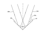
次に、図1のレンズ枠27及び凹面鏡24の6自由度の変位を計測するための変位センサとしてレーザ干渉計システムの構成につき図5及び図6を参照して説明する。
図5は、レンズ枠27及び凹面鏡24の変位計測用のレーザ干渉計システムを示し、この図5において、レンズ枠27の周縁部の上面には等角度間隔で3箇所に互いに垂直な2つの反射面を持つコーナーミラー部27a,27b,27c(移動鏡)が形成されている。3個のコーナーミラー部27a〜27cの2つの反射面の交線を延長した直線(以下、「稜線」と呼ぶ。)は、或る平面上に120°間隔で配置され、それら3本の稜線は凹面鏡24の中心を通りZ軸に平行な直線の近傍で交差する。コーナーミラー部27a〜27cは、例えばレンズ枠27の一部を鏡面加工して形成することも可能であるが、ガラス製の2つの反射面を持つコーナーミラーをレンズ枠27の切り欠き部に埋め込んでもよい。
Next, the configuration of the laser interferometer system as a displacement sensor for measuring the displacement of 6 degrees of freedom of the
FIG. 5 shows a laser interferometer system for measuring the displacement of the
本例では、一例としてそれら3本の稜線の水平方向(横方向)の位置とZ方向の位置(高さ)とを計測することによって、レンズ枠27(凹面鏡24)の6自由度の位置を一意的に決定する。例えば、図1の第2フレーム22に固定されているレーザ干渉計から一つのコーナーミラー部27aに対し、互いに角度の異なる2本の計測ビームを当てる。それらの計測ビームを用いることで、2つの計測ビームを法線とする平面が定義され、それら2つの平面の交線が一つの稜線となるため、2つの平面までの距離を計測することができ、その稜線の水平方向及びZ方向の位置を計測できる。
In this example, by measuring the horizontal direction (lateral direction) position and the Z direction position (height) of the three ridge lines as an example, the position of the lens frame 27 (concave mirror 24) with six degrees of freedom is determined. Determine uniquely. For example, two measurement beams having different angles are applied to one
その計測を行うため、レンズ枠27のコーナーミラー部27a,27b,27cの上方にそれぞれ2軸のレーザ干渉計50A,50B,50Cが配置されている。レーザ干渉計50A〜50Cを構成する各部材は、実際には図1の第2フレーム22(フレーム機構)の底面に直接に又は所定の取り付け部材を介して固定されている。
3個のレーザ干渉計50A〜50Cの構成は互いに同一であるため、以下ではレーザ干渉計50Aの構成につき説明する。レーザ干渉計50Aにおいて、レーザ光源35から射出された所定波長のレーザビームはビームスプリッタ36で2分割され、一方のレーザビームL1は偏光ビームスプリッタ37Aでさらに計測ビームL1m及び参照ビームL1rに分割される。一例として偏光ビームスプリッタ37Aには光合成用の偏光ビームスプリッタ38A(参照鏡)が固定されており、前者の偏光ビームスプリッタ37Aで反射された参照ビームL1rは偏光ビームスプリッタ38Aで再び反射される。一方、偏光ビームスプリッタ37Aを透過した計測ビームL1mはコーナーミラー部27aに入射して、入射方向と平行に逆方向に反射されて偏光ビームスプリッタ38Aを透過して参照ビームL1rと合成される。合成された計測ビームL1m及び参照ビームL1rは不図示の偏光板を経て光電検出器39Aに入射し、光電検出器39Aの検出信号がミラー制御系12の位置検出部に供給される。その位置検出部では、偏光ビームスプリッタ38Aの位置を基準としてコーナーミラー部27aの一方の反射面の位置を例えば分解能1nm程度で計測する。
In order to perform the measurement,
Since the three
また、ビームスプリッタ36で分割された他方のレーザビームL2は、不図示の送光光学系を介して偏光ビームスプリッタ37Bに入射して2分割される。一例として偏光ビームスプリッタ37Bにも光合成用の偏光ビームスプリッタ38B(参照鏡)が固定されており、前者の偏光ビームスプリッタ37Bで反射された参照ビームL2rは偏光ビームスプリッタ38Bで再び反射される。一方、偏光ビームスプリッタ37Bを透過した計測ビームL2mはコーナーミラー部27aに入射して、入射方向と平行に逆方向に反射されて偏光ビームスプリッタ38Bを透過して参照ビームL2rと合成される。合成された計測ビームL2m及び参照ビームL2rは不図示の偏光板を経て光電検出器39Bに入射し、光電検出器39Bの検出信号がミラー制御系12の位置検出部に供給される。その位置検出部では、偏光ビームスプリッタ38Bの位置を基準としてコーナーミラー部27aの他方の反射面の位置を例えば分解能1nm程度で計測する。本実施の形態においては、レーザ光源35、ビームスプリッタ36、偏光ビームスプリッタ37A及び37B、偏光ビームスプリッタ38A及び38B、並びに光電検出器39A及び39Bを含んでレーザ干渉計50Aが構成されているが、必ずしもこの構成に限定されるものではない。また、レーザ光源35、光電検出器39A,39Bが干渉計部に対応している。
The other laser beam L2 divided by the
図6は、図5中のコーナーミラー部27aを示す拡大図であり、この図6において、コーナーミラー部27aの2つの反射面A1及びA2にそれぞれ計測ビームL1m及びL2mがほぼ対称に、かつ入射面が反射面A2及びA1にほぼ垂直になるように入射している。このとき、反射面A1及びA2は互いに垂直であるため、反射面A1に入射した計測ビームL1mは、次に反射面A2で反射面A1に対する入射方向にほぼ平行な逆方向に反射される。これと対称に、反射面A2に入射した計測ビームL2mは次に、反射面A1で反射面A2に対する入射方向にほぼ平行な逆方向に反射される。このようにコーナーミラー部27aを用いることによって、その位置でレンズ枠27の水平方向及びZ方向の位置が変化しても、計測ビームL1m,L2mを用いてコーナーミラー部27aの稜線の水平方向及びZ方向の位置を高精度に計測できる。
FIG. 6 is an enlarged view showing the
図5に戻り、他のレーザ干渉計50B及び50Cも同様にコーナーミラー部27b及び27cの2方向の位置情報を含む検出信号をミラー制御系12の位置検出部に供給する。その位置検出部では、レーザ干渉計50B及び50C内の偏光ビームスプリッタの位置を基準としてそれぞれコーナーミラー部27b及び27cの稜線の水平方向及びZ方向の位置を例えば分解能1nm程度で計測する。このとき、レンズ枠27が目標とする位置にあれば、それら3本の稜線の位置は所定の目標とする直線の位置と一致する。レンズ枠27が微小変位するとき、コーナーミラー部27a〜27cの3個の稜線の位置からレンズ枠27の位置及び姿勢が一意的に決定される。そこで一例として、その位置検出部では、その3個の稜線の位置をそれぞれ目標とする位置に戻すように、図1の6軸の非接触のXY軸アクチュエータ32A〜32C(図2参照)及びZ軸アクチュエータ33A〜33Cの動作を制御する。これによって、レンズ枠27及び凹面鏡24の位置は第2フレーム22に対して目標とする位置に維持される。
Returning to FIG. 5, the other laser interferometers 50 </ b> B and 50 </ b> C similarly supply a detection signal including position information of the
なお、別の処理方法として、その3箇所のコーナーミラー部27a〜27cのそれぞれ2方向の位置(全部で6自由度の位置情報)を処理することによって、レンズ枠27及び凹面鏡24の図1の第2フレーム22に対するX方向、Y方向、Z方向の位置、及びX軸、Y軸、Z軸の周りの傾斜角を求めてもよい。これらの位置及び傾斜角の情報を用いることによっても、図1の6軸のXY軸アクチュエータ32A〜32C及びZ軸アクチュエータ33A〜33Cの動作を高精度に制御できる。
As another processing method, the
同様に、図1の凹面鏡25(レンズ枠28)及ぶ凹面鏡26(レンズ枠29)についてもそれぞれ6軸のレーザ干渉計システム(不図示)が配置されており、このレーザ干渉計システムによって凹面鏡25及び26の第2フレーム22に対する6自由度の変位が計測されている。なお、凹面鏡24〜26(レンズ枠27〜29)の6自由度の変位を検出する変位センサとしては、加速度センサや位置センサを用いることも可能である。加速度センサとしては、圧電素子(ピエゾ素子等)で発生する電圧を検出する圧電型の加速度センサや、例えば歪みの大きさに応じてCMOSコンバータの論理閾値電圧が変化することを利用する半導体式の加速度センサ等を使用できる。また、位置センサとしては、例えば渦電流変位センサ、静電容量式変位センサ、又は光学式センサ等の非接触式のセンサを使用できる。
Similarly, a 6-axis laser interferometer system (not shown) is also arranged for each of the concave mirror 25 (lens frame 28) and the concave mirror 26 (lens frame 29) of FIG. A displacement of 6 degrees of freedom with respect to the 26th
なお、図1の6軸のXY軸アクチュエータ32A〜32C及びZ軸アクチュエータ33A〜33C等の凹面鏡24〜26の位置調整機構は、投影光学系PLの結像特性を補正する機構と兼用してもよい。本例では、凹面鏡24〜26の変位はかなり正確に予測可能であるため、結像特性の補正も高精度に行うことが可能である。
上述のように本例の露光装置の投影光学系PLにおいては、剛構造の第2フレーム22に対して柔構造の連結部材としての防振パッド31A〜31C等及びワイヤ30A〜30C等を介して、剛構造のレンズ枠27等及び凹面鏡24等がアクティブ・サスペンション方式で吊り下げて支持されている。このために以下のような利点がある。
Note that the position adjustment mechanisms of the
As described above, in the projection optical system PL of the exposure apparatus of this example, the
1)投影光学系PLは極めて単純な構造体の組み合わせからなり、機構部が軽量化でき、製造コストを低減できる。
2)レンズ枠27〜29(凹面鏡24〜26)が吊り下げて支持されており、連結部材の特に水平方向の振動の固有振動数は極めて小さいため、床面からの振動の影響は大幅に軽減される。従って、除振性能及び露光精度(重ね合わせ精度)等の装置性能が向上する。そして、仮に振動が問題化した場合にも、その伝達経路の特定が容易であり、例えば振動が伝わる部分に防振部材を追加する等の対策を容易に施すことができる。
1) The projection optical system PL is composed of a very simple combination of structures, the mechanism can be reduced in weight, and the manufacturing cost can be reduced.
2) Since the lens frames 27 to 29 (concave mirrors 24 to 26) are suspended and supported, and the natural frequency of the vibration of the connecting member in particular in the horizontal direction is extremely small, the influence of vibration from the floor surface is greatly reduced. Is done. Therefore, apparatus performance such as vibration isolation performance and exposure accuracy (overlay accuracy) is improved. And even if vibration becomes a problem, it is easy to specify the transmission path, and for example, it is possible to easily take measures such as adding an anti-vibration member to a portion where vibration is transmitted.
3)露光装置の環境温度が変化した場合、構造体の熱変形の予測も容易になるため、温度センサを用いて構造体の各部の温度を計測することによって、その計測結果に基づいて位置決め誤差等を補正することもできる。
4)投影光学系PL内の光学部材の周囲に広い空間があるので、設計の自由度が大きくなるとともに、所謂モジュール設計に好適な構造と言える。
3) Since the thermal deformation of the structure can be easily predicted when the environmental temperature of the exposure apparatus changes, positioning errors based on the measurement results can be obtained by measuring the temperature of each part of the structure using a temperature sensor. Etc. can also be corrected.
4) Since there is a wide space around the optical member in the projection optical system PL, the degree of freedom in design increases, and it can be said that the structure is suitable for so-called module design.
なお、上述の実施形態の露光装置は、複数のミラーから構成される照明光学系、投影光学系を露光装置本体に組み込み光学調整をして、多数の機械部品からなるマスクステージやウエハステージを露光装置本体に取り付けて配線や配管を接続し、総合調整(電気調整、動作確認等)をすることにより製造することができる。なお、その露光装置の製造は温度及びクリーン度等が管理されたクリーンルームで行うことが望ましい。 Note that the exposure apparatus of the above-described embodiment incorporates an illumination optical system and projection optical system composed of a plurality of mirrors into the exposure apparatus main body and performs optical adjustment to expose a mask stage and wafer stage made up of a large number of mechanical parts. It can be manufactured by attaching to the main body of the apparatus, connecting wiring and piping, and performing general adjustment (electrical adjustment, operation check, etc.). The exposure apparatus is preferably manufactured in a clean room where the temperature, cleanliness, etc. are controlled.
また、上記の実施形態の露光装置を用いて半導体デバイスを製造する場合、この半導体デバイスは、デバイスの機能・性能設計を行うステップ、このステップに基づいてレチクルを製造するステップ、シリコン材料からウエハを形成するステップ、上記の実施形態の露光装置によりアライメントを行ってレチクルのパターンをウエハに露光するステップ、エッチング等の回路パターンを形成するステップ、デバイス組み立てステップ(ダイシング工程、ボンディング工程、パッケージ工程を含む)、及び検査ステップ等を経て製造される。 Further, when a semiconductor device is manufactured using the exposure apparatus of the above-described embodiment, the semiconductor device includes a step of designing a function and performance of the device, a step of manufacturing a reticle based on this step, and a wafer from a silicon material. Forming step, aligning with the exposure apparatus of the above-described embodiment to expose the pattern of the reticle onto the wafer, forming circuit pattern such as etching, device assembly step (including dicing process, bonding process, and packaging process) ) And an inspection step.
なお、本発明は、投影用のビームとしてエキシマレーザ光(波長248nmのKrFエキシマレーザ光、波長193nmのArFエキシマレーザ光等)、F2 レーザ光(波長157nm)、又は固体レーザ(YAGレーザや半導体レーザ等)の高調波等の波長100〜300nm程度の紫外光を用いる露光装置の屈折型や反射屈折型等の投影光学系を支持する場合にも適用することができる。なお、支持する光学部材は、凹面鏡や平面鏡等のミラーのみならず、レンズ(屈折部材)であってもよいのは言うまでもない。また、本発明は、例えば国際公開(WO)第99/49504号などに開示される液浸型露光装置に装着された投影光学系を支持する場合にも適用することができる。 In the present invention, excimer laser light (KrF excimer laser light with a wavelength of 248 nm, ArF excimer laser light with a wavelength of 193 nm, etc.), F 2 laser light (wavelength of 157 nm), or solid-state laser (YAG laser or semiconductor) is used as a projection beam. The present invention can also be applied to the case of supporting a projection optical system such as a refraction type or a catadioptric type of an exposure apparatus that uses ultraviolet light having a wavelength of about 100 to 300 nm such as a harmonic of a laser. Needless to say, the supporting optical member may be a lens (refractive member) as well as a mirror such as a concave mirror or a plane mirror. The present invention can also be applied to support a projection optical system mounted on an immersion type exposure apparatus disclosed in, for example, International Publication (WO) No. 99/49504.
また、本発明は、半導体デバイス製造用の露光装置への適用に限定されることなく、例えば、角型のガラスプレートに形成される液晶表示素子、若しくはプラズマディスプレイ等のディスプレイ装置用の露光装置や、撮像素子(CCD等)、マイクロマシーン、薄膜磁気ヘッド、及びDNAチップ等の各種デバイスを製造するための露光装置にも広く適用できる。更に、本発明は、各種デバイスのマスクパターンが形成されたマスク(フォトマスク、レチクル等)をフォトリソグフィ工程を用いて製造する際の、露光工程(露光装置)にも適用することができる。 In addition, the present invention is not limited to application to an exposure apparatus for manufacturing a semiconductor device, for example, an exposure apparatus for a display device such as a liquid crystal display element formed on a square glass plate or a plasma display, It can also be widely applied to an exposure apparatus for manufacturing various devices such as an image sensor (CCD or the like), a micromachine, a thin film magnetic head, and a DNA chip. Furthermore, the present invention can also be applied to an exposure process (exposure apparatus) when manufacturing a mask (photomask, reticle, etc.) on which mask patterns of various devices are formed using a photolithographic process.
なお、本発明は上述の実施形態に限定されず、本発明の要旨を逸脱しない範囲で種々の構成を取り得ることは勿論である。 In addition, this invention is not limited to the above-mentioned embodiment, Of course, a various structure can be taken in the range which does not deviate from the summary of this invention.
本発明の露光装置によれば、除振性能に優れるとともに、簡単で軽量な構成の投影光学系を用いているため、露光精度を高く維持した上で、機構部の軽量化及び低コスト化が可能となる。 According to the exposure apparatus of the present invention, since the projection optical system having a simple and lightweight configuration is used while being excellent in vibration isolation performance, the exposure accuracy can be maintained high, and the weight and cost of the mechanism can be reduced. It becomes possible.
M…マスク、3…マスクステージ、PL…投影光学系、W…ウエハ、13…ウエハステージ、21…第1フレーム、22…第2フレーム、24,25,26…凹面鏡、27,28,29…レンズ枠、27a,27b,27c…コーナーミラー部、30A〜30C,30D,30E,30G,30H…ワイヤ、31A〜31C,31D,31E,31G,31H…防振パッド、32A〜32C,32D,32E,32G,32H…XY軸アクチュエータ、33A〜33C,33D〜33F,33G〜33I…Z軸アクチュエータ、41…シリンダー、42…ピストン、45A,45B…排気管、50A〜50C…レーザ干渉計
M ... Mask, 3 ... Mask stage, PL ... Projection optical system, W ... Wafer, 13 ... Wafer stage, 21 ... First frame, 22 ... Second frame, 24, 25, 26 ... Concave mirror, 27, 28, 29 ... Lens frame, 27a, 27b, 27c ... corner mirror part, 30A-30C, 30D, 30E, 30G, 30H ... wire, 31A-31C, 31D, 31E, 31G, 31H ... anti-vibration pad, 32A-32C, 32D, 32E , 32G, 32H ... XY axis actuator, 33A to 33C, 33D to 33F, 33G to 33I, Z axis actuator, 41 ... Cylinder, 42 ... Piston, 45A, 45B ... Exhaust pipe, 50A-50C ... Laser interferometer
Claims (15)
前記パターンからのビームを像面に導く複数の光学部材と、
前記複数の光学部材のうち少なくとも一つの光学部材を吊り下げて支持する連結部材とを備えたことを特徴とする投影光学系。 In a projection optical system that projects a pattern image,
A plurality of optical members for guiding the beam from the pattern to the image plane;
A projection optical system comprising: a connecting member that suspends and supports at least one of the plurality of optical members.
前記連結部材は、大気圧を用いて前記少なくとも一つの光学部材を支持する支持装置を備えていることを特徴とする請求項1に記載の投影光学系。 The plurality of optical members are arranged in a vacuum atmosphere,
The projection optical system according to claim 1, wherein the connecting member includes a support device that supports the at least one optical member using atmospheric pressure.
前記大気圧が供給されるシリンダー部と、
前記大気圧により前記シリンダー部中に浮上支持されるとともに、前記少なくとも一つの光学部材に接続されるピストン部と、
前記シリンダー部を包囲する包囲部を真空雰囲気に保つ排気部とを備えていることを特徴とする請求項2に記載の投影光学系。 The support device is
A cylinder part to which the atmospheric pressure is supplied;
A piston portion that is levitated and supported in the cylinder portion by the atmospheric pressure, and connected to the at least one optical member;
The projection optical system according to claim 2, further comprising: an exhaust portion that keeps the surrounding portion surrounding the cylinder portion in a vacuum atmosphere.
気体が供給されるシリンダー部と、
前記シリンダー部中に収納されて前記気体によって浮上支持されるとともに、前記吊り下げて支持される光学部材に接続されるピストン部と、
前記シリンダー部から漏れ出る気体を排気するための配管とを備えたことを特徴とする請求項7に記載の投影光学系。 The damping mechanism is
A cylinder part to which gas is supplied;
A piston part that is housed in the cylinder part and supported by being floated by the gas, and connected to the optical member that is supported by being suspended;
The projection optical system according to claim 7, further comprising a pipe for exhausting gas leaking from the cylinder portion.
前記吊り下げて支持される各光学部材の前記フレーム機構に対する6自由度の変位をそれぞれ計測する変位センサとをさらに備えたことを特徴とする請求項1から9のいずれか一項に記載の投影光学系。 A frame mechanism for supporting the connecting member;
The projection according to any one of claims 1 to 9, further comprising a displacement sensor that measures displacement of each of the optical members supported by being suspended with respect to the frame mechanism with six degrees of freedom. Optical system.
前記投影光学系による前記パターンの像を基板上に転写することを特徴とする露光装置。 An exposure apparatus comprising the projection optical system according to any one of claims 1 to 13,
An exposure apparatus for transferring an image of the pattern on the substrate by the projection optical system.
The exposure apparatus according to claim 14, wherein the beam is extreme ultraviolet light having a wavelength of 1 to 100 nm, and each of the plurality of optical members constituting the projection optical system is a mirror.
Priority Applications (1)
| Application Number | Priority Date | Filing Date | Title |
|---|---|---|---|
| JP2004330052A JP2006140366A (en) | 2004-11-15 | 2004-11-15 | Projection optical system and exposure device |
Applications Claiming Priority (1)
| Application Number | Priority Date | Filing Date | Title |
|---|---|---|---|
| JP2004330052A JP2006140366A (en) | 2004-11-15 | 2004-11-15 | Projection optical system and exposure device |
Publications (1)
| Publication Number | Publication Date |
|---|---|
| JP2006140366A true JP2006140366A (en) | 2006-06-01 |
Family
ID=36620969
Family Applications (1)
| Application Number | Title | Priority Date | Filing Date |
|---|---|---|---|
| JP2004330052A Pending JP2006140366A (en) | 2004-11-15 | 2004-11-15 | Projection optical system and exposure device |
Country Status (1)
| Country | Link |
|---|---|
| JP (1) | JP2006140366A (en) |
Cited By (23)
| Publication number | Priority date | Publication date | Assignee | Title |
|---|---|---|---|---|
| WO2007040254A1 (en) * | 2005-10-05 | 2007-04-12 | Nikon Corporation | Exposure apparatus and exposure method |
| JP2007321932A (en) * | 2006-06-02 | 2007-12-13 | Kurashiki Kako Co Ltd | Gas spring type vibration isolator |
| JP2008515219A (en) * | 2004-09-30 | 2008-05-08 | 株式会社ニコン | Projection optical apparatus and exposure apparatus |
| US7433050B2 (en) | 2005-10-05 | 2008-10-07 | Nikon Corporation | Exposure apparatus and exposure method |
| WO2008139964A1 (en) * | 2007-05-11 | 2008-11-20 | Nikon Corporation | Optical element driver, lens-barrel and exposure apparatus and method for fabricating device |
| JP2009158719A (en) * | 2007-12-26 | 2009-07-16 | Canon Inc | Exposure apparatus and method of manufacturing device |
| JP2012518272A (en) * | 2009-02-17 | 2012-08-09 | カール・ツァイス・エスエムティー・ゲーエムベーハー | Projection exposure apparatus provided with actuator system |
| US20130271945A1 (en) | 2004-02-06 | 2013-10-17 | Nikon Corporation | Polarization-modulating element, illumination optical apparatus, exposure apparatus, and exposure method |
| JP2013225674A (en) * | 2012-04-20 | 2013-10-31 | Carl Zeiss Smt Gmbh | Optical device capable of adjusting effect of force upon optical module |
| JP2014239234A (en) * | 2008-06-10 | 2014-12-18 | カール・ツァイス・エスエムティー・ゲーエムベーハー | Optical device that can adjust force action onto optical module |
| JP2015065475A (en) * | 2010-08-05 | 2015-04-09 | エーエスエムエル ネザーランズ ビー.ブイ. | Imprint lithography |
| US9341954B2 (en) | 2007-10-24 | 2016-05-17 | Nikon Corporation | Optical unit, illumination optical apparatus, exposure apparatus, and device manufacturing method |
| DE102015209076A1 (en) * | 2015-05-18 | 2016-06-09 | Carl Zeiss Smt Gmbh | Projection exposure system with actuator cables |
| WO2016087119A1 (en) * | 2014-12-04 | 2016-06-09 | Carl Zeiss Smt Gmbh | Mirror for a lithography system and lithography system |
| US9423698B2 (en) | 2003-10-28 | 2016-08-23 | Nikon Corporation | Illumination optical apparatus and projection exposure apparatus |
| US9678437B2 (en) | 2003-04-09 | 2017-06-13 | Nikon Corporation | Illumination optical apparatus having distribution changing member to change light amount and polarization member to set polarization in circumference direction |
| US9678332B2 (en) | 2007-11-06 | 2017-06-13 | Nikon Corporation | Illumination apparatus, illumination method, exposure apparatus, and device manufacturing method |
| CN107533956A (en) * | 2015-04-17 | 2018-01-02 | 株式会社尼康 | Exposure system |
| US9885872B2 (en) | 2003-11-20 | 2018-02-06 | Nikon Corporation | Illumination optical apparatus, exposure apparatus, and exposure method with optical integrator and polarization member that changes polarization state of light |
| US9891539B2 (en) | 2005-05-12 | 2018-02-13 | Nikon Corporation | Projection optical system, exposure apparatus, and exposure method |
| US10101666B2 (en) | 2007-10-12 | 2018-10-16 | Nikon Corporation | Illumination optical apparatus, exposure apparatus, and device manufacturing method |
| JP2019505825A (en) * | 2015-12-15 | 2019-02-28 | カール・ツァイス・エスエムティー・ゲーエムベーハー | Optical system especially for microlithographic projection exposure apparatus |
| JP2019505828A (en) * | 2015-12-03 | 2019-02-28 | カール・ツァイス・エスエムティー・ゲーエムベーハー | Optical imaging device with actively adjustable metrology support unit |
Citations (5)
| Publication number | Priority date | Publication date | Assignee | Title |
|---|---|---|---|---|
| JPH06250061A (en) * | 1993-02-26 | 1994-09-09 | Nikon Corp | Optical member holding device |
| WO2001022480A1 (en) * | 1999-09-20 | 2001-03-29 | Nikon Corporation | Parallel link mechanism, exposure system and method of manufacturing the same, and method of manufacturing devices |
| JP2002025903A (en) * | 2000-04-17 | 2002-01-25 | Asm Lithography Bv | Lithographic apparatus, method of device manufacture, and device manufactured thereby |
| JP2003203860A (en) * | 2001-12-21 | 2003-07-18 | Asml Netherlands Bv | Lithographic apparatus and method of manufacturing device |
| JP2004311626A (en) * | 2003-04-04 | 2004-11-04 | Nikon Corp | Aligner |
-
2004
- 2004-11-15 JP JP2004330052A patent/JP2006140366A/en active Pending
Patent Citations (5)
| Publication number | Priority date | Publication date | Assignee | Title |
|---|---|---|---|---|
| JPH06250061A (en) * | 1993-02-26 | 1994-09-09 | Nikon Corp | Optical member holding device |
| WO2001022480A1 (en) * | 1999-09-20 | 2001-03-29 | Nikon Corporation | Parallel link mechanism, exposure system and method of manufacturing the same, and method of manufacturing devices |
| JP2002025903A (en) * | 2000-04-17 | 2002-01-25 | Asm Lithography Bv | Lithographic apparatus, method of device manufacture, and device manufactured thereby |
| JP2003203860A (en) * | 2001-12-21 | 2003-07-18 | Asml Netherlands Bv | Lithographic apparatus and method of manufacturing device |
| JP2004311626A (en) * | 2003-04-04 | 2004-11-04 | Nikon Corp | Aligner |
Cited By (43)
| Publication number | Priority date | Publication date | Assignee | Title |
|---|---|---|---|---|
| US9678437B2 (en) | 2003-04-09 | 2017-06-13 | Nikon Corporation | Illumination optical apparatus having distribution changing member to change light amount and polarization member to set polarization in circumference direction |
| US9885959B2 (en) | 2003-04-09 | 2018-02-06 | Nikon Corporation | Illumination optical apparatus having deflecting member, lens, polarization member to set polarization in circumference direction, and optical integrator |
| US9760014B2 (en) | 2003-10-28 | 2017-09-12 | Nikon Corporation | Illumination optical apparatus and projection exposure apparatus |
| US9423698B2 (en) | 2003-10-28 | 2016-08-23 | Nikon Corporation | Illumination optical apparatus and projection exposure apparatus |
| US9885872B2 (en) | 2003-11-20 | 2018-02-06 | Nikon Corporation | Illumination optical apparatus, exposure apparatus, and exposure method with optical integrator and polarization member that changes polarization state of light |
| US10281632B2 (en) | 2003-11-20 | 2019-05-07 | Nikon Corporation | Illumination optical apparatus, exposure apparatus, and exposure method with optical member with optical rotatory power to rotate linear polarization direction |
| US10234770B2 (en) | 2004-02-06 | 2019-03-19 | Nikon Corporation | Polarization-modulating element, illumination optical apparatus, exposure apparatus, and exposure method |
| US10007194B2 (en) | 2004-02-06 | 2018-06-26 | Nikon Corporation | Polarization-modulating element, illumination optical apparatus, exposure apparatus, and exposure method |
| US10241417B2 (en) | 2004-02-06 | 2019-03-26 | Nikon Corporation | Polarization-modulating element, illumination optical apparatus, exposure apparatus, and exposure method |
| US20130271945A1 (en) | 2004-02-06 | 2013-10-17 | Nikon Corporation | Polarization-modulating element, illumination optical apparatus, exposure apparatus, and exposure method |
| JP4656448B2 (en) * | 2004-09-30 | 2011-03-23 | 株式会社ニコン | Projection optical apparatus and exposure apparatus |
| US8767172B2 (en) | 2004-09-30 | 2014-07-01 | Nikon Corporation | Projection optical device and exposure apparatus |
| JP2008515219A (en) * | 2004-09-30 | 2008-05-08 | 株式会社ニコン | Projection optical apparatus and exposure apparatus |
| US9891539B2 (en) | 2005-05-12 | 2018-02-13 | Nikon Corporation | Projection optical system, exposure apparatus, and exposure method |
| US8064067B2 (en) | 2005-10-05 | 2011-11-22 | Nikon Corporation | Exposure apparatus and exposure method |
| US7433050B2 (en) | 2005-10-05 | 2008-10-07 | Nikon Corporation | Exposure apparatus and exposure method |
| WO2007040254A1 (en) * | 2005-10-05 | 2007-04-12 | Nikon Corporation | Exposure apparatus and exposure method |
| JP2007321932A (en) * | 2006-06-02 | 2007-12-13 | Kurashiki Kako Co Ltd | Gas spring type vibration isolator |
| WO2008139964A1 (en) * | 2007-05-11 | 2008-11-20 | Nikon Corporation | Optical element driver, lens-barrel and exposure apparatus and method for fabricating device |
| US10101666B2 (en) | 2007-10-12 | 2018-10-16 | Nikon Corporation | Illumination optical apparatus, exposure apparatus, and device manufacturing method |
| US9341954B2 (en) | 2007-10-24 | 2016-05-17 | Nikon Corporation | Optical unit, illumination optical apparatus, exposure apparatus, and device manufacturing method |
| US9857599B2 (en) | 2007-10-24 | 2018-01-02 | Nikon Corporation | Optical unit, illumination optical apparatus, exposure apparatus, and device manufacturing method |
| US9678332B2 (en) | 2007-11-06 | 2017-06-13 | Nikon Corporation | Illumination apparatus, illumination method, exposure apparatus, and device manufacturing method |
| JP2009158719A (en) * | 2007-12-26 | 2009-07-16 | Canon Inc | Exposure apparatus and method of manufacturing device |
| JP2014239234A (en) * | 2008-06-10 | 2014-12-18 | カール・ツァイス・エスエムティー・ゲーエムベーハー | Optical device that can adjust force action onto optical module |
| US10175581B2 (en) | 2008-06-10 | 2019-01-08 | Carl Zeiss Smt Gmbh | Optical apparatus with adjustable action of force on an optical module |
| US9766549B2 (en) | 2008-06-10 | 2017-09-19 | Carl Zeiss Smt Gmbh | Optical apparatus with adjustable action of force on an optical module |
| JP2012518272A (en) * | 2009-02-17 | 2012-08-09 | カール・ツァイス・エスエムティー・ゲーエムベーハー | Projection exposure apparatus provided with actuator system |
| US9030644B2 (en) | 2009-02-17 | 2015-05-12 | Carl Zeiss Smt Gmbh | Projection exposure apparatus for semiconductor lithography including an actuator system |
| US10908510B2 (en) | 2010-08-05 | 2021-02-02 | Asml Netherlands B.V. | Imprint lithography |
| US10890851B2 (en) | 2010-08-05 | 2021-01-12 | Asml Netherlands B.V. | Imprint lithography |
| US11635696B2 (en) | 2010-08-05 | 2023-04-25 | Asml Netherlands B.V. | Imprint lithography |
| US9864279B2 (en) | 2010-08-05 | 2018-01-09 | Asml Netherlands B.V. | Imprint lithography |
| JP2015065475A (en) * | 2010-08-05 | 2015-04-09 | エーエスエムエル ネザーランズ ビー.ブイ. | Imprint lithography |
| JP2013225674A (en) * | 2012-04-20 | 2013-10-31 | Carl Zeiss Smt Gmbh | Optical device capable of adjusting effect of force upon optical module |
| WO2016087119A1 (en) * | 2014-12-04 | 2016-06-09 | Carl Zeiss Smt Gmbh | Mirror for a lithography system and lithography system |
| CN107003620A (en) * | 2014-12-04 | 2017-08-01 | 卡尔蔡司Smt有限责任公司 | The speculum and etching system of etching system |
| CN107533956A (en) * | 2015-04-17 | 2018-01-02 | 株式会社尼康 | Exposure system |
| DE102015209076A1 (en) * | 2015-05-18 | 2016-06-09 | Carl Zeiss Smt Gmbh | Projection exposure system with actuator cables |
| JP2019505828A (en) * | 2015-12-03 | 2019-02-28 | カール・ツァイス・エスエムティー・ゲーエムベーハー | Optical imaging device with actively adjustable metrology support unit |
| US10890850B2 (en) | 2015-12-03 | 2021-01-12 | Carl Zeiss Smt Gmbh | Optical imaging arrangement with actively adjustable metrology support units |
| JP2019505825A (en) * | 2015-12-15 | 2019-02-28 | カール・ツァイス・エスエムティー・ゲーエムベーハー | Optical system especially for microlithographic projection exposure apparatus |
| US10838306B2 (en) | 2015-12-15 | 2020-11-17 | Carl Zeiss Smt Gmbh | Optical system, in particular for a microlithographic projection exposure apparatus |
Similar Documents
| Publication | Publication Date | Title |
|---|---|---|
| JP2006140366A (en) | Projection optical system and exposure device | |
| JP4656448B2 (en) | Projection optical apparatus and exposure apparatus | |
| JP5109661B2 (en) | Exposure apparatus and exposure method | |
| US8598538B2 (en) | Movable body apparatus, object processing device, exposure apparatus, flat-panel display manufacturing method, and device manufacturing method | |
| US8064067B2 (en) | Exposure apparatus and exposure method | |
| KR100855527B1 (en) | Holding device, holding method, exposure device, and device manufacturing method | |
| TWI691796B (en) | Movable body apparatus, exposure apparatus, flat-panel display manufacturing method, and device manufacturing method | |
| KR20190131146A (en) | Object processing apparatus, exposure apparatus and exposure method, and device manufacturing method | |
| KR20120055574A (en) | Object moving apparatus, object processing apparatus, exposure apparatus, object inspecting apparatus and device manufacturing method | |
| JPWO2006022200A1 (en) | Stage apparatus and exposure apparatus | |
| TWI728425B (en) | Movable body apparatus, exposure apparatus, manufacturing method of flat panel display, and device manufacturing method | |
| KR20080088580A (en) | Exposure device and fabrication method thereof | |
| JPWO2009084199A1 (en) | Exposure apparatus, exposure method, and device manufacturing method | |
| CN105493237B (en) | Movable body apparatus, exposure apparatus, and device manufacturing method | |
| JPWO2005048325A1 (en) | Stage driving method, stage apparatus, and exposure apparatus | |
| JP6689489B2 (en) | Mobile device, exposure apparatus, flat panel display manufacturing method, and device manufacturing method | |
| JP2024029010A (en) | Stage equipment, exposure equipment, flat panel display manufacturing method, and device manufacturing method | |
| JP2011232628A (en) | Movable body apparatus, exposure apparatus, device manufacturing method and manufacturing method of flat panel display | |
| JP5578485B2 (en) | MOBILE DEVICE, EXPOSURE APPARATUS, AND DEVICE MANUFACTURING METHOD | |
| JP2008166614A (en) | Moving object apparatus, aligner, measurement method, exposure method, and method of manufacturing device | |
| JP2005217303A (en) | Aligner and method for manufacturing device | |
| JP2010010593A (en) | Vibrationproof device, stage apparatus, and aligner | |
| JP6508268B2 (en) | Mobile body apparatus, exposure apparatus, method of manufacturing flat panel display, and method of manufacturing device | |
| JP2009076584A (en) | Supporting system, stage system, exposure device, exposure method, and device manufacturing method | |
| JP2008203105A (en) | Position measuring method and instrument, and exposure device |
Legal Events
| Date | Code | Title | Description |
|---|---|---|---|
| A621 | Written request for application examination |
Free format text: JAPANESE INTERMEDIATE CODE: A621 Effective date: 20070921 |
|
| A977 | Report on retrieval |
Free format text: JAPANESE INTERMEDIATE CODE: A971007 Effective date: 20100409 |
|
| A131 | Notification of reasons for refusal |
Free format text: JAPANESE INTERMEDIATE CODE: A131 Effective date: 20100413 |
|
| A02 | Decision of refusal |
Free format text: JAPANESE INTERMEDIATE CODE: A02 Effective date: 20100804 |