JP2006136102A - Motor drive control device - Google Patents
Motor drive control device Download PDFInfo
- Publication number
- JP2006136102A JP2006136102A JP2004321149A JP2004321149A JP2006136102A JP 2006136102 A JP2006136102 A JP 2006136102A JP 2004321149 A JP2004321149 A JP 2004321149A JP 2004321149 A JP2004321149 A JP 2004321149A JP 2006136102 A JP2006136102 A JP 2006136102A
- Authority
- JP
- Japan
- Prior art keywords
- motor
- phase
- current
- voltage
- drive control
- Prior art date
- Legal status (The legal status is an assumption and is not a legal conclusion. Google has not performed a legal analysis and makes no representation as to the accuracy of the status listed.)
- Withdrawn
Links
Images


Landscapes
- Control Of Motors That Do Not Use Commutators (AREA)
Abstract
【課題】 インバータ回路から直流側の母線に還流する電流によってコンデンサの寿命が低下することを防止することが可能なモータの駆動制御装置を提供すること。
【解決手段】 モータ制御部は、電流ゼロクロスが予想される区間のみ一時的に進んだ電圧ベクトルを出力し、(e)に示すように、電流のゼロクロス前後での母線電流の極性変化に基づいてゼロクロスを検出する。
そして、(d)、(e)、(f)に示すように、電流と電圧の位相差を検出するとともに、(c)、(g)、(h)に示すように、速やかに固定相を切り替えることで、できる限り直流側へ還流する電流を発生させないようにしている。
【選択図】 図5PROBLEM TO BE SOLVED: To provide a drive control device for a motor capable of preventing a life of a capacitor from being reduced by a current flowing from an inverter circuit to a bus on the DC side.
A motor control unit outputs a voltage vector that is temporarily advanced only in a section in which a current zero cross is expected, and based on a change in polarity of a bus current before and after the current zero cross, as shown in (e). Detect zero cross.
Then, as shown in (d), (e), (f), the phase difference between the current and voltage is detected, and as shown in (c), (g), (h), the stationary phase is quickly changed. By switching, as much as possible the current that flows back to the DC side is not generated.
[Selection] Figure 5
Description
本発明は、モータの駆動制御装置に関し、特に、インバータ回路を用いたモータ駆動を制御するためのモータ駆動制御装置に関する。 The present invention relates to a motor drive control device, and more particularly to a motor drive control device for controlling motor drive using an inverter circuit.
従来技術として、下記特許文献1に開示された同期モータの駆動制御装置がある。このモータ駆動制御装置では、インバータ回路の各アームのスイッチング素子を全てオフとする回生モードを有し、モータコイルに流れる電流を、インバータ回路に直流電圧を入力する一対の母線間に設けられたコンデンサに回生するようになっている。
しかしながら、上記従来技術のモータ駆動制御装置では、コンデンサの内部インピーダンスが大きい場合には、逆にリップル電流による損失が大きく、効率が悪化するとともに、コンデンサ内部の温度上昇により、コンデンサ寿命の低下を招くという問題がある。 However, in the motor drive control device of the above prior art, when the internal impedance of the capacitor is large, the loss due to the ripple current is large, the efficiency is deteriorated, and the lifetime of the capacitor is reduced due to the temperature rise inside the capacitor. There is a problem.
本発明は、上記点に鑑みてなされたものであり、インバータ回路から直流側の母線に還流する電流によってコンデンサの寿命が低下することを防止することが可能なモータの駆動制御装置を提供することを目的とする。 The present invention has been made in view of the above points, and provides a motor drive control device capable of preventing the life of a capacitor from being reduced by a current flowing back from an inverter circuit to a DC bus. With the goal.
上記目的を達成するため、請求項1に記載の発明では、
複数相のモータコイルに、インバータ回路(16)の前記複数相に対応したスイッチング素子(161)のスイッチングに基づいて、直流電圧をPWM変調により交流に変換して印加し、モータ(12)を駆動するモータの駆動制御装置であって、
モータコイルに流れる電流が、インバータ回路(16)に直流電圧を印加するための母線(15)に還流することを抑制するように、前記複数相のうちスイッチング素子(161)のオンオフ状態を固定する相を決定することを特徴としている。
In order to achieve the above object, in the invention described in
Based on the switching of the switching element (161) corresponding to the plurality of phases of the inverter circuit (16), the DC voltage is converted into alternating current by PWM modulation and applied to the motor coil of the plurality of phases to drive the motor (12). A motor drive control device,
The on / off state of the switching element (161) among the plurality of phases is fixed so as to suppress the current flowing through the motor coil from flowing back to the bus (15) for applying a DC voltage to the inverter circuit (16). It is characterized by determining the phase.
これによると、複数相のモータコイルに対応したスイッチング素子(161)のうち、オンオフ状態を固定する相を、母線(15)に還流する電流を抑制するように決定する。したがって、母線(15)間にコンデンサ(151)を設けていても、コンデンサ寿命の低下を招き難い。このようにして、インバータ回路(16)から直流側の母線(15)に還流する電流によってコンデンサ(151)の寿命が低下することを防止することができる。 According to this, among the switching elements (161) corresponding to the motor coils of a plurality of phases, the phase that fixes the on / off state is determined so as to suppress the current flowing back to the bus (15). Therefore, even if the capacitor (151) is provided between the bus bars (15), it is difficult to reduce the capacitor life. In this way, it is possible to prevent the life of the capacitor (151) from being reduced by the current flowing back from the inverter circuit (16) to the bus (15) on the DC side.
また、請求項2に記載の発明では、オンオフ状態を固定する相は、前記モータコイルに流れる電流の絶対値が最大の相とすることを特徴としている。 According to a second aspect of the present invention, the phase for fixing the on / off state is a phase in which the absolute value of the current flowing through the motor coil is the maximum.
これによると、インバータ回路(16)から直流側の母線(15)に還流する電流を抑制することが容易である。また、スイッチング損失を低減することができる。 According to this, it is easy to suppress the current flowing back from the inverter circuit (16) to the DC side bus (15). Moreover, switching loss can be reduced.
また、請求項3に記載の発明では、前記複数相のモータコイル電流のいずれかがゼロクロスしたときに、オンオフ状態を固定する相を切り替えることを特徴としている。 According to a third aspect of the present invention, when any one of the motor coil currents of the plurality of phases crosses zero, the phase for fixing the on / off state is switched.
これによると、モータコイルに流れる電流の絶対値が最大の相を速やかに固定する相とすることが容易である。 According to this, it is easy to make the phase with the maximum absolute value of the current flowing through the motor coil a phase that quickly fixes.
また、請求項4に記載の発明のように、母線(15)に流れる電流の極性情報に基づいて、モータコイル電流のゼロクロスを容易に検出することができる。 In addition, as in the fourth aspect of the invention, the zero crossing of the motor coil current can be easily detected based on the polarity information of the current flowing through the bus (15).
また、請求項5に記載の発明では、モータコイル電流の絶対値が最大の相の電圧が、複数相のうちで最大値もしくは最小値でない場合には、モータコイル電流の絶対値が前記最大の相に次いで大きい相を、固定する相とすることを特徴としている。 In the invention according to claim 5, when the voltage of the phase having the maximum absolute value of the motor coil current is not the maximum value or the minimum value among the plurality of phases, the absolute value of the motor coil current is the maximum value. The phase that is larger than the phase is a fixed phase.
これによると、モータコイルへの印加電圧とモータコイル電流との位相差が大きくなり、モータコイル電流の絶対値最大相を固定する相とすると相間電圧が設定できなくなる場合であっても、モータコイル電流の絶対値比較に基づいて固定する相を決定して対応することができる。 According to this, even if the phase difference between the applied voltage to the motor coil and the motor coil current becomes large and the phase of the motor coil current is fixed, the phase of the motor coil current cannot be set. The phase to be fixed can be determined and dealt with based on the absolute value comparison of the current.
また、請求項6に記載の発明では、モータコイル電流の絶対値が最大の相の電圧が、複数相のうちで最大値もしくは最小値でない場合には、電圧の絶対値が最大の相を、固定する相とすることを特徴としている。 In the invention according to claim 6, when the voltage of the phase having the maximum absolute value of the motor coil current is not the maximum value or the minimum value among the plurality of phases, the phase having the maximum absolute value of the voltage is It is characterized by a fixed phase.
これによると、モータコイルへの印加電圧とモータコイル電流との位相差大きくなり、モータコイル電流の絶対値最大相を固定する相とすると相間電圧が設定できなくなる場合であっても、モータコイル印加電圧絶対値に基づいて固定する相を決定して対応することができる。 According to this, the phase difference between the voltage applied to the motor coil and the motor coil current becomes large, and even if the phase voltage cannot be set if the absolute phase maximum phase of the motor coil current is fixed, the motor coil applied The phase to be fixed can be determined and dealt with based on the voltage absolute value.
また、請求項7に記載の発明では、モータ(12)の運転負荷が所定値より小さいときには、電圧の絶対値が最大の相を、固定する相とすることを特徴としている。 According to the seventh aspect of the present invention, when the operating load of the motor (12) is smaller than a predetermined value, the phase having the maximum absolute value of the voltage is set as a fixed phase.
これによると、モータコイル電流の絶対値最大相が入れ替わったか否かを判断し難い場合には、モータコイル印加電圧絶対値に基づいて固定する相を決定し、誤動作を防止することができる。 According to this, when it is difficult to determine whether or not the maximum phase of the absolute value of the motor coil current has been switched, it is possible to determine a phase to be fixed based on the absolute value of the applied voltage of the motor coil and prevent malfunction.
また、請求項8に記載の発明では、インバータ回路(16)における変調率が所定値より大きいときには、電圧の絶対値が最大の相を、固定する相とすることを特徴としている。 The invention according to claim 8 is characterized in that when the modulation rate in the inverter circuit (16) is larger than a predetermined value, the phase having the maximum voltage absolute value is set as a fixed phase.
これによると、過変調制御時に、モータコイル電流の絶対値最大相を固定する相とすると相間電圧の歪みが大きくなってしまう場合であっても、モータコイル印加電圧絶対値に基づいて固定する相を決定して対応することができる。 According to this, during overmodulation control, if the phase that fixes the maximum phase of the absolute value of the motor coil current is fixed, the phase that is fixed based on the absolute value of the applied voltage of the motor coil even if the distortion of the interphase voltage increases. Can be determined.
また、請求項9に記載の発明では、
複数相のモータコイルに、インバータ回路(16)の前記複数相に対応したスイッチング素子(161)のスイッチングに基づいて、直流電圧をPWM変調により交流に変換して印加し、モータ(12)を駆動するモータの駆動制御装置であって、
インバータ回路(16)に直流電圧を印加するための母線(15)に流れる電流の極性情報に基づいて、モータコイルに印加される電圧とモータコイルに流れる電流との位相差を検出することを特徴としている。
In the invention according to claim 9,
Based on the switching of the switching element (161) corresponding to the plurality of phases of the inverter circuit (16), the DC voltage is converted into alternating current by PWM modulation and applied to the motor coil of the plurality of phases to drive the motor (12). A motor drive control device,
A phase difference between the voltage applied to the motor coil and the current flowing to the motor coil is detected based on polarity information of the current flowing to the bus bar (15) for applying a DC voltage to the inverter circuit (16). It is said.
これによると、モータコイル印加電圧と、母線電流極性情報に基づくモータコイル電流のゼロクロス検出とから、モータコイル印加電圧とモータコイル電流との位相差を検出することができる。したがって、この位相差に基づいて、ロータ位置センサを用いないモータの駆動制御が可能である。 According to this, the phase difference between the motor coil applied voltage and the motor coil current can be detected from the motor coil applied voltage and the zero cross detection of the motor coil current based on the bus current polarity information. Therefore, based on this phase difference, drive control of the motor without using the rotor position sensor is possible.
また、請求項10に記載の発明では、
複数相のモータコイルに、インバータ回路(16)の前記複数相に対応したスイッチング素子(161)のスイッチングに基づいて、直流電圧をPWM変調により交流に変換して印加し、モータ(12)を駆動するモータの駆動制御装置であって、
インバータ回路(16)に直流電圧を印加するための母線(15)に流れる電流の極性情報に基づいて、モータ(12)への回転数指令に応じてモータコイルに流す目標電流位相と、モータコイルに流れる実電流位相との位相偏差を検出することを特徴としている。
In the invention according to
Based on the switching of the switching element (161) corresponding to the plurality of phases of the inverter circuit (16), the DC voltage is converted into alternating current by PWM modulation and applied to the motor coil of the plurality of phases to drive the motor (12). A motor drive control device,
Based on the polarity information of the current flowing in the bus (15) for applying a DC voltage to the inverter circuit (16), the target current phase to be passed through the motor coil in response to the rotational speed command to the motor (12), and the motor coil It is characterized by detecting a phase deviation from the phase of the actual current flowing through the current.
これによると、回転数指令に基づく目標電流位相と、母線電流極性情報に基づくモータコイル実電流位相との位相偏差を検出することができる。したがって、この位相偏差に基づいて、ロータ位置センサを用いないモータの駆動制御が可能である。 According to this, it is possible to detect a phase deviation between the target current phase based on the rotational speed command and the motor coil actual current phase based on the bus current polarity information. Therefore, based on this phase deviation, motor drive control without using the rotor position sensor is possible.
また、請求項11に記載の発明のように、母線(15)に流れる電流の極性情報は、母線(15)に設けたシャント抵抗部(152)に発生する電圧をコンパレータ回路(130)で検出することで、容易に得ることができる。 Further, as in the invention described in claim 11, the polarity information of the current flowing through the bus (15) is detected by the comparator circuit (130) by detecting the voltage generated in the shunt resistor (152) provided on the bus (15). By doing so, it can be easily obtained.
また、請求項12に記載の発明では、複数回路を同一パッケージに内蔵したオペアンプ(124a、130a)を用いて、母線(15)に流れる電流の極性情報を検出する回路(130)と、モータ(12)の運転負荷情報を検出する回路(124)とを構成したことを特徴としている。
In the invention according to
これによると、両情報検出回路(124、130)を同一パッケージ内のオペアンプ(124a、130a)を用いて構成することで、部品点数を減少することが可能である。 According to this, it is possible to reduce the number of parts by configuring both information detection circuits (124, 130) using operational amplifiers (124a, 130a) in the same package.
また、請求項13に記載の発明では、モータ(12)は同期モータ(12)であって、位置センサを用いることなく、モータコイルに印加される電圧とモータコイルに流れる電流との位相差に基づいて、同期モータ(12)を駆動制御することを特徴としている。
In the invention according to
このように、本発明は、モータコイル印加電圧とモータコイル電流との位相差に基づいて同期モータ(12)の位置センサレス駆動制御を行なう制御装置に適用することができる。 Thus, the present invention can be applied to a control device that performs position sensorless drive control of the synchronous motor (12) based on the phase difference between the motor coil applied voltage and the motor coil current.
また、請求項14に記載の発明では、モータ(12)が運転する負荷は、圧縮機構(11)であることを特徴としている。
Further, the invention described in
このように、圧縮機構(11)により圧縮される被圧縮流体の漏れ抑止を考慮するとロータ位置センサを設け難いコンプレッサモータの駆動制御装置に、本発明を適用することができる。 In this way, the present invention can be applied to a compressor motor drive control device in which it is difficult to provide a rotor position sensor in consideration of leakage suppression of the fluid to be compressed compressed by the compression mechanism (11).
また、請求項15に記載の発明では、モータ(12)が運転する負荷は、送風ファン(51)であることを特徴としている。
Further, the invention described in
また、請求項16に記載の発明では、モータ(12)が運転する負荷は、流体を圧送するポンプ機構(90)であることを特徴としている。
Further, the invention described in
これらのように、送風ファン(51)やポンプ機構(90)を運転するモータを位置センサレス駆動制御する駆動制御装置に本発明を適用することも可能である。 As described above, the present invention can also be applied to a drive control device that performs position sensorless drive control of a motor that operates the blower fan (51) and the pump mechanism (90).
なお、上記各手段に付した括弧内の符号は、後述する実施形態記載の具体的手段との対応関係を示す一例である。 In addition, the code | symbol in the parenthesis attached | subjected to each said means is an example which shows a corresponding relationship with the specific means as described in embodiment mentioned later.
以下、本発明の実施の形態を図に基づいて説明する。 Hereinafter, embodiments of the present invention will be described with reference to the drawings.
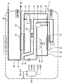
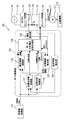
本実施形態は、本発明に係るモータ駆動制御装置を、二酸化炭素を冷媒とするヒートポンプ式給湯装置のヒートポンプサイクル1中の電動圧縮機10の制御装置として適用したものであり、図1は、本実施形態に係るヒートポンプ給湯装置の概略要部構成を示す模式図である。また、図2は、本実施形態におけるモータの位置センサレス駆動制御装置である電動圧縮機10の同期モータ12のモータ駆動制御部120概略構成を示すブロック図である。
In the present embodiment, the motor drive control device according to the present invention is applied as a control device for the
図1に示すように、ヒートポンプサイクル1は、圧縮機10、給湯用熱交換器(水冷媒熱交換器)20、エジェクタ(減圧手段)30、アキュムレータ40、室外熱交換器(熱源用熱交換器)50、内部熱交換器60、およびこれらを環状に接続する冷媒配管70で構成されている。
As shown in FIG. 1, a
圧縮機10は、内蔵する同期モータ(本実施形態におけるモータ)12(図2参照)によって圧縮機構11(図2参照)が運転されて、気相冷媒を臨界圧力以上まで圧縮して吐出する電動コンプレッサである。
The
給湯用熱交換器20は、圧縮機10の吐出口より吐出された高温高圧の冷媒によって水を湯に昇温させる水−冷媒熱交換器であり、冷媒が流通する冷媒通路部と水が流通する水通路部とにより構成されている。給湯用熱交換器20の冷媒通路部は冷媒流路管により構成され、冷媒通路部が水通路部の表面に熱交換可能に密着するように配置された熱交換構造となっている。
The hot water supply heat exchanger 20 is a water-refrigerant heat exchanger that heats water to hot water by a high-temperature and high-pressure refrigerant discharged from the discharge port of the
給湯用熱交換器20の水通路部は、給水を流通する給水通路(流水路)80の一部を構成しており、ポンプ(ポンプ機構)90の作動により給水通路80内を流れる水を、給湯用熱交換器20内で高温高圧冷媒との熱交換によって給湯用の高温の湯とするようになっている。
The water passage portion of the hot water supply heat exchanger 20 constitutes a part of a water supply passage (flow water passage) 80 through which water is circulated, and the water flowing through the
室外熱交換器(蒸発器)50は、外気と液相冷媒とを熱交換させて液相冷媒を蒸発させることにより外気から吸熱するための熱交換器である。また、エジェクタ30は給湯用熱交換器20から流出する冷媒を減圧膨張させて室外熱交換器50にて蒸発した気相冷媒を吸引するとともに、膨張エネルギーを圧力エネルギーに変換して圧縮機10の吸入圧を上昇させるものである。
The outdoor heat exchanger (evaporator) 50 is a heat exchanger for absorbing heat from the outside air by exchanging heat between the outside air and the liquid phase refrigerant to evaporate the liquid phase refrigerant. Further, the
ここで、エジェクタ30は、給湯用熱交換器20から流出した高圧冷媒の圧力エネルギーを速度エネルギーに変換して冷媒を略等エントロピ的に減圧膨張させるノズル部と、ノズル部から噴射する高い速度の冷媒流により室外熱交換器50にて蒸発した気相冷媒を吸引しながら、ノズル部から噴射する冷媒流と混合する混合部、およびノズル部から噴射する冷媒と室外熱交換器50から吸引した冷媒とを混合させながら速度エネルギーを圧力エネルギーに変換して冷媒の圧力を昇圧させるディフューザ等の昇圧部からなるものである。
Here, the
エジェクタ30のノズル部は、ノズル開度を調節するための図示しないニードル弁を有しており、ニードル弁は図示しないステッピングモータの作動によりノズル部の軸線方向に駆動するようになっている。
The nozzle portion of the
また、アキュムレータ40は、エジェクタ30から流出した冷媒が流入するとともに、その流入した冷媒を気相冷媒と液相冷媒とに分離して冷媒を蓄える気液分離器であり、分離された気相冷媒は内部熱交換器60を介して圧縮機10に吸引され、分離された液相冷媒は室外熱交換器50側に吸引されるようになっている。
The
内部熱交換器60は、アキュムレータ40から導出され室外熱交換器50の一部において外気と熱交換した低圧気相冷媒と、エジェクタ30にて減圧される前の高圧側の冷媒とを熱交換する熱交換器であり、この内部熱交換器60により圧縮機10吸入側での冷媒のエンタルピを上昇させて、超臨界ヒートポンプサイクル1の能力を向上させている。
The
また、ヒートポンプサイクル1には、圧縮機10の吐出側と室外熱交換器50の上流側とを連通する連通配管78と、この連通配管78の経路を開閉する電磁弁79が設けられている。この連通配管78は除霜用の冷媒配管であって、電磁弁79が開弁すると、連通配管78を介して高温冷媒が室外熱交換器50に導入され、室外熱交換器50の除霜を行なうことができるようになっている。
Further, the
図1に示すように、冷媒配管70には、圧縮機10の吐出冷媒温度を検出する吐出温サーミスタ71、給湯用熱交換器20下流側の冷媒温度を検出する冷媒出口サーミスタ72、室外熱交換器50上流側の冷媒温度を検出するエバ入口サーミスタ73、室外熱交換器50下流側の冷媒温度を検出するフロストサーミスタ74、およびエジェクタ30上流側においてヒートポンプサイクル1の高圧側冷媒圧力を検出する圧力センサ75が設けられている。
As shown in FIG. 1, a
また、室外熱交換器50の空気流れ上流側面には、電動ファン(送風ファン)51の作動により室外熱交換器50を通過する前の外気の温度を検出する外気サーミスタ52が設けられている。
An
一方、給水通路80には、給湯用熱交換器20上流側の水温を検出する給水サーミスタ81、および給湯用熱交換器20下流側の水温を検出する給湯サーミスタ82が設けられている。
On the other hand, a
上記各サーミスタ52、71〜74、81、82から温度情報、および圧力センサ75からの圧力情報は、制御ユニット100に入力される。そして、この制御ユニット100は、上記各情報および図示しない操作手段や検出手段からの入力信号に基づいて、圧縮機10、エジェクタ30、電動ファン51、電磁弁79、ポンプ90等を作動制御するようになっている。
The temperature information from the
図2に示すように、圧縮機10は、同期モータ12により負荷としての圧縮機構11を回転運動させ、冷媒を圧縮して吐出するものであり、本実施形態の同期モータ12は、磁石を埋設したロータを回転駆動する4極3相コイルを有する同期モータである。
As shown in FIG. 2, the
外部電源19からの交流電圧が入力線13を介してAC/DCコンバータ回路14に入力され、直流電圧に変換されて母線15を介してインバータ回路16に入力される。インバータ回路16は、後述する制御ユニット100のモータ制御部120からの信号に基づいて同期モータ12のステータコイルの各相(U、V、W相)に電圧を印加し、ロータが回転駆動される。
An AC voltage from the
なお、一対の母線15間には、コンデンサ(例えば、直流側の平滑手段としての電解コンデンサやスナバコンデンサとしてのフィルムコンデンサ)151が設けられている。 A capacitor (for example, an electrolytic capacitor as a DC side smoothing means or a film capacitor as a snubber capacitor) 151 is provided between the pair of bus bars 15.
制御ユニット100は、共通のマイコン内に、ヒートポンプサイクル1を含むヒートポンプ式給湯装置本体部を制御するための給湯器制御部110と、本実施形態における同期モータの位置センサレス駆動制御装置としてのモータ制御部120とを備えている。
The
モータ制御部120は、本実施形態における目標位相差設定手段としての目標位相差制御部121、目標電流位相設定手段としての目標位相制御部122、位相偏差検出手段としての位相偏差検出部123、負荷情報検出手段としての負荷情報検出部124、印加電圧設定手段としての電圧振幅制御部125およびモータ印加電圧波形生成部126、母線電流極性検出手段としての極性検出部130を備えている。
The
負荷情報検出部124は、図3に示すように、母線15に接続した負荷情報検出回路(積分回路)からなり、母線15に流れる電流に基づいて負荷情報を検出するようになっている。
As shown in FIG. 3, the load
また、極性検出部130は、図3に示すように、母線15に接続したコンパレータ回路からなり、母線15に設けたシャント抵抗部152との構成により、母線15に流れる電流の極性情報を検出するようになっている。
Further, as shown in FIG. 3, the
なお、図示は省略しているが、負荷情報検出部124に用いられているオペアンプ124aと、極性検出部130に用いられているオペアンプ130aとは、同一パッケージ内に集積されたオペアンプのうちの2つとしている。このように、コンパレータにオペアンプを使用した場合、センサレスの力率角制御に必要な負荷情報を検出するための積分回路と、同一パッケージのオペアンプを使用することで安価に構成でき、安価な回路と、安価なマイコンで、位置センサレスの正弦波駆動が実現できる。
Although not shown, the
目標位相差制御部121では、上位制御部である給湯器制御部110からの回転数指令と負荷情報検出部124からの負荷情報に基づいて、ROMに格納したマップもしくは演算式(本例ではマップ)により、同期モータ12の駆動制御におけるコイルへの印加電圧とモータコイル電流との目標位相差が設定される。
In the target phase
また、目標位相制御部122では、給湯器制御部110からの回転数指令に応じて目標電流位相が更新される。そして、位相偏差検出部123では、目標位相制御部122で更新された目標電流位相に基づくゼロクロス(目標ゼロクロス)と、極性検出部130が検出した母線電流極性情報に基づく実ゼロクロス(検出ゼロクロス)とから、位相偏差を検出する。
In target
電圧振幅制御部125では、給湯器制御部110からの回転数指令に基づいて基底電圧振幅を設定するとともに、位相偏差検出部123で検出された位相偏差が所定値(本例では0)になるように印加電圧振幅を制御する。
The voltage
モータ印加電圧波形生成部126では、目標位相差制御部121において設定された目標位相差、目標位相制御部122において更新された目標電流位相、および電圧振幅制御部125において設定された印加電圧振幅、極性検出部130において検出された母線電流極性情報に基づく検出ゼロクロスから、モータ12への印加電圧波形情報を生成し、前述のインバータ回路16に出力する。
In the motor applied voltage
インバータ回路16は、図3に示すように周知の構造をなしており、モータ12のステータコイルに対応したU、V、W相の3相分のアームからなる。
As shown in FIG. 3, the
U相のアームは、スイッチング素子161とダイオード162とを逆並列接続した上アームU1と、同じくスイッチング素子161とダイオード162とを逆並列接続した下アームU2とを直列接続して構成され、上アームU1と下アームU2との接続部がモータコイルに接続されている。
The U-phase arm is configured by serially connecting an upper arm U1 in which a
V相アームおよびW相アームも、スイッチング素子161とダイオード162とにより同様に構成されている。
The V-phase arm and the W-phase arm are similarly configured by the switching
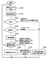
ここで、モータ印加電圧波形生成部126におけるインバータ回路16の制御について説明する。図4は、モータ印加電圧波形生成部126の制御動作を説明するためのフローチャートである。
Here, control of the
モータ印加電圧波形生成部126は、まず、極性検出部130からの入力に基づいていずれかの相の電流のゼロクロスを検出したら(ステップS100)、電流区間を更新する(ステップS110)。
First, when the motor applied voltage
そして、次に、負荷情報検出部124において検出した負荷(モータ12の運転負荷)がモータコイル電流2A相当以下であるか否か判断する(ステップS120)。図2では、負荷情報検出部124からモータ印加電圧波形生成部126への入力図示を省略している。
Next, it is determined whether or not the load detected by the load information detection unit 124 (operation load of the motor 12) is equal to or less than the motor coil current 2A (step S120). In FIG. 2, the input from the load
ステップS120において、負荷が2A相当以下であると判断した場合には、電流ゼロクロスの信頼性が低いと判断して、ステップS180へ進む。ステップS120において、負荷が2A相当を越えると判断した場合には、変調率が1.15471以上であるか否か(過変調であるか否か)判断する(ステップS130)。ステップS130において、過変調であると判断した場合には、ステップS180へ進む。 If it is determined in step S120 that the load is equal to or less than 2 A, it is determined that the reliability of the current zero cross is low, and the process proceeds to step S180. If it is determined in step S120 that the load exceeds 2A, it is determined whether the modulation rate is 1.15471 or more (whether it is overmodulation) (step S130). If it is determined in step S130 that the signal is overmodulated, the process proceeds to step S180.
ステップS130において過変調でないと判断した場合には、電流の絶対値が最大の相をその電流区間における基準相とする(ステップS140)。そして、基準相と他相との電圧指令を比較し、基準相の電圧が最大値もしくは最小値であるか否か判断する(ステップS150)。 If it is determined in step S130 that the current is not overmodulated, the phase having the maximum current absolute value is set as the reference phase in the current section (step S140). Then, the voltage commands of the reference phase and the other phase are compared, and it is determined whether or not the voltage of the reference phase is the maximum value or the minimum value (step S150).
基準相の電圧が最大値もしくは最小値でない場合、すなわち、基準相の電圧が正に場合には基準相より他相が大きいとき、もしくは基準相の電圧が負に場合には基準相より他相が小さいときには、ステップS170へ進む。 If the reference phase voltage is not the maximum or minimum value, that is, if the reference phase voltage is positive, the other phase is greater than the reference phase, or if the reference phase voltage is negative, the other phase than the reference phase When is smaller, the process proceeds to step S170.
ステップS150において基準相の電圧が最大値もしくは最小値であると判断した場合には、ステップS160へ進み、基準相のスイッチング素子161のオンオフ状態を固定する。
If it is determined in step S150 that the reference phase voltage is the maximum value or the minimum value, the process proceeds to step S160, and the on / off state of the reference
ステップS150において基準相の電圧が最大値もしくは最小値でないと判断した場合には、ステップS170において電流の絶対値が最大の相に次いで大きい相を固定相とし、この相のスイッチング素子161のオンオフ状態を固定する。なお、ステップS170では、電圧指令絶対値が最大の相を固定相としてもよい。
When it is determined in step S150 that the voltage of the reference phase is not the maximum value or the minimum value, in step S170, the phase having the second largest absolute value of the current is set as the stationary phase, and the
ステップS120で電流ゼロクロスの信頼性が低いと判断した場合、およびステップS130で過変調であると判断した場合には、ステップS180において電圧の絶対値が最大の相を固定相とし、この相のスイッチング素子161のオンオフ状態を固定する。
If it is determined in step S120 that the reliability of the current zero cross is low and if it is determined in step S130 that the current is overmodulated, in step S180, the phase having the maximum absolute value of the voltage is set as a stationary phase, and switching of this phase is performed. The on / off state of the
ステップS160、S170、S180のいずれかを実行したらステップS100へリターンする。 When one of steps S160, S170, and S180 is executed, the process returns to step S100.
上述の構成および制御動作によれば、スイッチングに伴なう損失を低減することができる。スイッチング素子161の1回のON/OFFで生じる損失wは、下記の数式1のようになり、電流値にほぼ比例する。
According to the above-described configuration and control operation, it is possible to reduce a loss due to switching. The loss w generated by one ON / OFF of the
(数式1)
w≒(1/2)E×Ion×ton+(1/2)E×Ion×toff
ただし、Eは直流側電圧、Ionは電流、ton、toffはスイッチング時間である。
(Formula 1)
w≈ (1/2) E × Ion × ton + (1/2) E × Ion × toff
However, E is a DC side voltage, Ion is a current, and ton and toff are switching times.
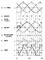
したがって、図5に示すように、電流の絶対値が高い相を固定とすることで、スイッチング損失を低減することができる。 Therefore, as shown in FIG. 5, the switching loss can be reduced by fixing the phase having a high absolute value of the current.
ちなみに、図5において、(a)はモータ12の各相に流れる電流、(b)は電流のゼロクロスに応じて更新される電流区間である。(c)は図4のステップS140で更新される基準相を示しており、Uは、基準相が固定相となる場合の上アームU1がON、下アームU2がOFFの状態を示し、U′は、上アームU1がOFF、下アームU2がONの状態を示すものである。VおよびV′、WおよびW′も同様である。
Incidentally, in FIG. 5, (a) is a current flowing through each phase of the
また、(d)は電圧指令(比較波形の原型)、(e)は極性検出部130が検出する母線電流極性、(f)はモータコイルへの印加電圧と電流との位相差である。(g)は基準相を固定相とするための重畳波であり、(h)は電圧指令に重畳波を重畳して生成された相電圧(2相変調の実質的な比較波形)である。
Further, (d) is a voltage command (an original of a comparison waveform), (e) is a bus current polarity detected by the
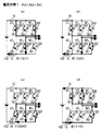
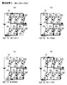
インバータ回路16の各スイッチング素子161のスイッチング周期は、基本的に図6に示すように、60°の空間を囲む2つの電圧ベクトルと、零ベクトルE(000)もしくはE(111)とで構成される。図6に例示する電圧ベクトルe、電流ベクトルiの状態では、電圧ベクトルE(101)とE(100)ならびに零ベクトルE(000)の電圧パターンで構成される。
As shown in FIG. 6, the switching cycle of each switching
ここで、電圧ベクトルのON、OFFパターンの表示は、括弧内に順にU相、V相、W相の各アームのスイッチング素子の状態を示しており、1は上アームがONかつ下アームがOFF、0は上アームがOFFかつ下アームがONの状態を示している。 Here, the ON / OFF pattern display of the voltage vector indicates the state of the switching elements of the U-phase, V-phase, and W-phase arms in parentheses. 1 indicates that the upper arm is ON and the lower arm is OFF. , 0 indicates a state in which the upper arm is OFF and the lower arm is ON.
図6に例示する電圧ベクトルe、電流ベクトルiの状態は、電流区間Iで、各素子のON/OFF状態と、電流の向きは、図7(a)、(b)、(c)に示すようになる。この状態から時間が経過し、W相の電流極性が反転、すなわち電流区間IIとなると、各素子のON/OFF状態と、電流の向きは、図8(a)、(b)、(c)となる。 The state of the voltage vector e and the current vector i illustrated in FIG. 6 is the current section I, and the ON / OFF state of each element and the current direction are shown in FIGS. 7 (a), (b), and (c). It becomes like this. When time elapses from this state and the W-phase current polarity is reversed, that is, in current section II, the ON / OFF state of each element and the current direction are shown in FIGS. 8A, 8B, and 8C. It becomes.
ここで、W相の電流極性が反転するときに、電圧ベクトルeを120°の空間を囲む2つの電圧ベクトルE(101)とE(110)ならびに零ベクトルE(000)の電圧パターンで構成すると、図7(d)のように、電圧ベクトルE(110)出力時に電流区間Iでは、負荷に流れる電流から直流側への回生(還流)が発生する。一方、図8(d)のように、電流区間IIでは、負荷に流れる電流から直流側への回生(還流)は発生しない。 Here, when the current polarity of the W phase is inverted, the voltage vector e is composed of voltage patterns of two voltage vectors E (101) and E (110) and a zero vector E (000) surrounding a 120 ° space. As shown in FIG. 7D, regeneration (recirculation) from the current flowing through the load to the DC side occurs in the current section I when the voltage vector E (110) is output. On the other hand, as shown in FIG. 8D, regeneration (recirculation) from the current flowing through the load to the DC side does not occur in the current section II.
このように、電流のゼロクロスが予想される区間のみ、一時的に進んだ電圧ベクトルを出力することで、図5(e)に示すように、電流のゼロクロス前後で母線電流の極性が変化するため、母線電流極性からゼロクロスを検出することができる。 In this way, by outputting the voltage vector that is temporarily advanced only in the section where the current zero crossing is expected, the polarity of the bus current changes before and after the current zero crossing as shown in FIG. The zero cross can be detected from the bus current polarity.
このとき、図5(d)、(e)、(f)に示すように、母線電流極性変化が検出されたときの電圧位相から、電流と電圧の位相差を検出するとともに、図5(c)、(g)、(h)に示すように、速やかに固定相を切り替えることで、できる限り回生電流(直流側へ還流する電流)を発生させないようにする。 At this time, as shown in FIGS. 5D, 5E, and 5F, the phase difference between the current and the voltage is detected from the voltage phase when the change in bus current polarity is detected, and FIG. ), (G), and (h), by quickly switching the stationary phase, the regenerative current (current flowing back to the DC side) is prevented from being generated as much as possible.
このように、回生電流を発生させないようにすることで、モータ電流のリップルが抑えられ、モータ鉄損やノイズを低減することができるとともに、直流側のコンデンサ151(平滑手段である電解コンデンサやスナバコンデンサ)へのリップル電流が減少し、特に、電解コンデンサの内部抵抗ESR等の損失を低減することができる。 Thus, by not generating the regenerative current, the ripple of the motor current can be suppressed, the motor iron loss and noise can be reduced, and the DC-side capacitor 151 (an electrolytic capacitor or a snubber that is a smoothing means) can be reduced. The ripple current to the capacitor) is reduced, and in particular, the loss such as the internal resistance ESR of the electrolytic capacitor can be reduced.
また、電解コンデンサのリップル電流の低減は、コンデンサ内部温度の低減にもなり、コンデンサ151の長寿命化を図ることができる。
Further, the reduction of the ripple current of the electrolytic capacitor also reduces the internal temperature of the capacitor, and the life of the
また、電流位相を基準として固定相を決める場合、電圧と電流の位相差が±30°以上
(電流位相に対して電圧位相が進んでいる場合の位相差を正とする)になると、固定したい相(基準相)の電圧が最大または最小の相ではなくなり、固定したい相を1または−1にすると、1または−1以上となる相が発生し、電圧歪みを生じる。
Also, when the fixed phase is determined based on the current phase, if the phase difference between the voltage and current is ± 30 ° or more (the phase difference when the voltage phase is advanced with respect to the current phase is positive), it is desired to fix it. When the phase (reference phase) voltage is not the maximum or minimum phase and the phase to be fixed is set to 1 or -1, a phase of 1 or -1 or more is generated and voltage distortion occurs.
このような歪みは、電流波形を歪ませ、トルク変動による不安定な挙動につながり、これが著しくなると、電流ゼロクロスの誤検知→電流区間の誤判定→固定相の誤り→モータ脱調となる。 Such distortion distorts the current waveform and leads to unstable behavior due to torque fluctuation. When this becomes significant, erroneous detection of current zero crossing → erroneous determination of current section → error of stationary phase → motor step-out.
電流位相を基準とした従来の技術(例えば、特開2004−104861号公報開示技術)では、一般に負荷の力率は1に近くなるので問題にならないとし、+30°以上になった場合、強制的にステージ(通常時の電流区間に当たる)を進めることで、予め不確定要素として排除する仕組みとしている。しかし、弱め界磁制御を実施した場合、位相差は−30°以下となる。 In the conventional technique based on the current phase (for example, the technique disclosed in Japanese Patent Application Laid-Open No. 2004-104861), the load power factor is generally close to 1, so that there is no problem. The stage (corresponding to the normal current section) is advanced to eliminate the indeterminate element in advance. However, when field weakening control is performed, the phase difference is −30 ° or less.
また、過変調制御を実施した場合、電流位相を基準としたまま固定相を決め、ピークカットをすると相間電圧の歪みが大きくなってしまう。 In addition, when overmodulation control is performed, if the stationary phase is determined with the current phase as a reference and the peak is cut, the distortion of the interphase voltage becomes large.
さらに、負荷(電流)が小さくなると、電流ゼロクロスの検出が不安定になり、誤った固定相判定により、著しい電圧歪み→モータ脱調となるリスクが高い。 Furthermore, when the load (current) is reduced, detection of the current zero cross becomes unstable, and there is a high risk of significant voltage distortion → motor step-out due to erroneous stationary phase determination.
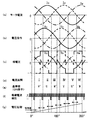
ところが、本実施形態では、図4のフローチャートに示すように、負荷が所定値以上に小さくなった場合および変調率が所定値以上に大きくなった場合には、ステップS180において電圧の絶対値の最大相を固定相としている。これにより、図10に過変調時のモータ電流、電流区間、基準相、電圧指令、固定相、重畳波、相電圧を例示するように制御される。 However, in this embodiment, as shown in the flowchart of FIG. 4, when the load becomes smaller than a predetermined value or when the modulation rate becomes larger than a predetermined value, the maximum absolute value of the voltage is determined in step S180. The phase is a stationary phase. As a result, the motor current, the current section, the reference phase, the voltage command, the stationary phase, the superimposed wave, and the phase voltage during overmodulation are illustrated in FIG.
ここで、負荷の所定値は、電流ゼロクロスの検出が不安定にならない範囲で、位相差が±90°以上とならないような値にしており、変調率の所定値は、1.5471以下で、位相差が±90°以上にならないような値にしている。 Here, the predetermined value of the load is a value in which the phase difference does not become ± 90 ° or more in a range where the detection of the current zero cross does not become unstable, and the predetermined value of the modulation factor is 1.5471 or less, The value is set so that the phase difference does not exceed ± 90 °.
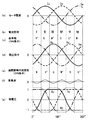
また、上記以外の場合にも、従来技術(前述の特開2004−104861号公報開示技術)のように電流区間を強制的に進めることはせず、各区間で、固定したい相(基準相)とその他の相の電圧を比較して、最終的に固定する相を決めている。これにより、図9に位相差が−60°時のモータ電流、電流区間、基準相、電圧指令、固定相、重畳波、相電圧を例示するように制御される。 Also, in cases other than the above, the current section is not forcibly advanced as in the prior art (the technique disclosed in Japanese Patent Application Laid-Open No. 2004-104861 described above), and the phase (reference phase) to be fixed in each section is not required. And the voltage of other phases are compared, and finally the phase to be fixed is determined. As a result, the motor current, current section, reference phase, voltage command, stationary phase, superimposed wave, and phase voltage when the phase difference is −60 ° are illustrated in FIG.
ちなみに、ステップS160を実行するときには、図5に例示するように制御される。 Incidentally, when step S160 is executed, control is performed as illustrated in FIG.
位相差が±30°以上で固定したい相(基準相)が最終的に固定する相にできない場合、電流の絶対値が次に大きな相が固定相となるようにすることで、損失増加を最小限に抑制することができる。 When the phase difference is ± 30 ° or more and the phase to be fixed (reference phase) cannot be finally fixed, the increase in loss is minimized by making the phase with the next largest absolute value of the current the fixed phase. It can be suppressed to the limit.
このように、本実施形態のモータ駆動制御によれば、弱め界磁制御や過変調制御においても、簡易かつ安定に動作させることができる。 Thus, according to the motor drive control of the present embodiment, it is possible to operate simply and stably even in the field weakening control or overmodulation control.
また、力率角制御との組み合わせにおいて、簡易かつ安定した動作を、処理負荷の少ないロジックで実現でき、比較的安価なマイコンで位置センサレス制御を実現することができる。 Further, in combination with power factor angle control, simple and stable operation can be realized with logic with a small processing load, and position sensorless control can be realized with a relatively inexpensive microcomputer.
(他の実施形態)
上記一実施形態では、母線電流極性に基づく電流ゼロクロス検出によって、固定相の切り替えをおこなっているが、これに限定されるものではなく、磁極位置推定演算によって、電流位相を検出して、その角度により切り替えをおこなってもよいし、ホール素子などの位置センサによって検出されるロータ回転位置に基づいて切り替えをおこなってもよい。
(Other embodiments)
In the above embodiment, the fixed phase is switched by the current zero cross detection based on the bus current polarity, but the present invention is not limited to this, and the current phase is detected by the magnetic pole position estimation calculation, and the angle is detected. The switching may be performed based on the rotor rotational position detected by a position sensor such as a Hall element.
また、上記一実施形態では、電流ゼロクロス検出は、母線電流極性に基づいて検出していたが、モータ電流から検出するものであってもよい。また、電流ゼロクロス検出は、電流位相検出としてもかまわない。 In the above embodiment, the current zero cross detection is detected based on the bus current polarity, but may be detected from the motor current. Further, the current zero cross detection may be a current phase detection.
また、上記一実施形態では、負荷情報検出部124が検出し、運転負荷の判定に用いる情報は、モータ電流でなく入力電流であってもよい。
Further, in the above-described embodiment, the information detected by the load
また、上記一実施形態では、負荷情報検出部124を構成する負荷情報検出回路は、積分回路であったが、ピークホールド回路でもよい。
In the above embodiment, the load information detection circuit constituting the load
また、上記一実施形態では、電圧と電流の位相差は、電圧位相を基準として電流ゼロクロス時の位相差を求めるものであったが、これに限定されるものではなく、電流位相を基準として、位相偏差を求めるものでもよい。 Further, in the one embodiment, the phase difference between the voltage and the current is obtained by obtaining the phase difference at the time of the current zero cross with reference to the voltage phase, but is not limited thereto, and with the current phase as a reference, A phase deviation may be obtained.
また、上記一実施形態では、モータは、同期モータ(PMモータ、リラクタンスモータなど)であったが、誘導モータであってもかまわない。弱め界磁制御は同期モータ固有の制御であるが、誘導モータに対する過変調制御等においては本発明を適用することができる。 In the above embodiment, the motor is a synchronous motor (such as a PM motor or a reluctance motor), but may be an induction motor. The field weakening control is a control unique to the synchronous motor, but the present invention can be applied to overmodulation control or the like for the induction motor.
また、正弦波変調PWMの方法(サブハーモニック変調方式、空間ベクトル方式など)を限定するものでもない。 Further, the method of sine wave modulation PWM (sub-harmonic modulation method, space vector method, etc.) is not limited.
また、上記一実施形態では、同期モータ12は、二酸化炭素を冷媒とするヒートポンプサイクル1の圧縮機構11を運転するモータであったが、これに限定されるものではない。冷媒が二酸化炭素以外のヒートポンプサイクル(冷凍サイクル)の圧縮機モータであってもよいし、負荷は圧縮機構ではなく電動ファン(送風ファン)51やポンプ(ポンプ機構)90等であってもよい。モータを駆動制御する場合に、本発明は広く適用して有効である。
Moreover, in the said one Embodiment, although the
また、上記一実施形態では、母線電流極性情報に基づいて電流ゼロクロスを検出して電流区間を更新し、基準相の更新や固定相の決定を行なっていたが、母線電流情報に基づいて、モータコイル印加電圧とモータコイル電流との位相差、もしくは目標電流位相と実電流位相との位相偏差を検出し、この位相差もしくは位相偏差に基づいて、ロータ位置センサを用いないモータの駆動制御を行なうことが可能である。 In the above-described embodiment, the current zero cross is detected based on the bus current polarity information and the current section is updated, and the reference phase is updated and the fixed phase is determined. The phase difference between the coil applied voltage and the motor coil current or the phase deviation between the target current phase and the actual current phase is detected, and the drive control of the motor without using the rotor position sensor is performed based on this phase difference or phase deviation. It is possible.
例えば、図11に示すように、電流位相と無関係に(上記一実施形態における基準相とは無関係に)下側に固定した場合(各相の下アームを順次ON状態に固定した場合)や、図12に示すように、電流位相と無関係に上下交互に固定した場合においても、母線電流極性に基づいて電圧と電流の位相差を検出し、この位相差に基づいてモータの位置センサレス制御を行なうことができる。 For example, as shown in FIG. 11, when fixed to the lower side (regardless of the reference phase in the above-described one embodiment) regardless of the current phase (when the lower arm of each phase is sequentially fixed to the ON state) As shown in FIG. 12, even when the top and bottom are alternately fixed regardless of the current phase, the phase difference between the voltage and the current is detected based on the bus current polarity, and the position sensorless control of the motor is performed based on this phase difference. be able to.
1 ヒートポンプサイクル
10 圧縮機
11 圧縮機構(負荷)
12 同期モータ(モータ)
15 母線
16 インバータ回路
51 電動ファン(送風ファン)
90 ポンプ(ポンプ機構)
120 モータ制御部(モータ駆動制御部、同期モータの位置センサレス駆動制御装置)
124 負荷情報検出部(負荷情報検出手段)
126 モータ印加電圧波形生成部
130 極性検出部(コンパレータ回路)
124a、130a オペアンプ
151 コンデンサ
152 シャント抵抗部
161 スイッチング素子
U1、V1、W1 上アーム
U2、V2、W2 下アーム
1
12 Synchronous motor (motor)
15
90 Pump (pump mechanism)
120 Motor controller (motor drive controller, synchronous motor position sensorless drive controller)
124 Load information detection unit (load information detection means)
126 Motor Applied Voltage
124a, 130a
Claims (16)
前記モータコイルに流れる電流が、前記インバータ回路(16)に前記直流電圧を印加するための母線(15)に還流することを抑制するように、前記複数相のうちスイッチング素子(161)のオンオフ状態を固定する相を決定することを特徴とするモータの駆動制御装置。 Based on the switching of the switching element (161) corresponding to the plurality of phases of the inverter circuit (16), the DC voltage is converted into alternating current by PWM modulation and applied to the motor coil of the plurality of phases to drive the motor (12). A motor drive control device,
The on / off state of the switching element (161) of the plurality of phases is controlled so that the current flowing through the motor coil is prevented from flowing back to the bus (15) for applying the DC voltage to the inverter circuit (16). A drive control device for a motor, wherein a phase for fixing the motor is determined.
前記インバータ回路(16)に前記直流電圧を印加するための母線(15)に流れる電流の極性情報に基づいて、前記モータコイルに印加される電圧と前記モータコイルに流れる電流との位相差を検出することを特徴とするモータの駆動制御装置。 Based on the switching of the switching element (161) corresponding to the plurality of phases of the inverter circuit (16), the DC voltage is converted into alternating current by PWM modulation and applied to the motor coil of the plurality of phases to drive the motor (12). A motor drive control device,
Based on the polarity information of the current flowing through the bus (15) for applying the DC voltage to the inverter circuit (16), the phase difference between the voltage applied to the motor coil and the current flowing through the motor coil is detected. A drive control apparatus for a motor.
前記インバータ回路(16)に前記直流電圧を印加するための母線(15)に流れる電流の極性情報に基づいて、前記モータ(12)への回転数指令に応じて前記モータコイルに流す目標電流位相と、前記モータコイルに流れる実電流位相との位相偏差を検出することを特徴とするモータの駆動制御装置。 Based on the switching of the switching element (161) corresponding to the plurality of phases of the inverter circuit (16), the DC voltage is converted into alternating current by PWM modulation and applied to the motor coil of the plurality of phases to drive the motor (12). A motor drive control device,
Based on polarity information of the current flowing in the bus (15) for applying the DC voltage to the inverter circuit (16), the target current phase to be passed through the motor coil in accordance with the rotational speed command to the motor (12) And a phase deviation between the phase of the actual current flowing in the motor coil and the motor drive control device.
位置センサを用いることなく、前記モータコイルに印加される電圧と前記モータコイルに流れる電流との位相差に基づいて、前記同期モータ(12)を駆動制御することを特徴とする請求項1ないし請求項12のいずれか1つに記載のモータの駆動制御装置。 The motor (12) is a synchronous motor (12),
The synchronous motor (12) is driven and controlled based on a phase difference between a voltage applied to the motor coil and a current flowing through the motor coil without using a position sensor. Item 13. The motor drive control device according to any one of Items 12 above.
Priority Applications (1)
| Application Number | Priority Date | Filing Date | Title |
|---|---|---|---|
| JP2004321149A JP2006136102A (en) | 2004-11-04 | 2004-11-04 | Motor drive control device |
Applications Claiming Priority (1)
| Application Number | Priority Date | Filing Date | Title |
|---|---|---|---|
| JP2004321149A JP2006136102A (en) | 2004-11-04 | 2004-11-04 | Motor drive control device |
Publications (1)
| Publication Number | Publication Date |
|---|---|
| JP2006136102A true JP2006136102A (en) | 2006-05-25 |
Family
ID=36729118
Family Applications (1)
| Application Number | Title | Priority Date | Filing Date |
|---|---|---|---|
| JP2004321149A Withdrawn JP2006136102A (en) | 2004-11-04 | 2004-11-04 | Motor drive control device |
Country Status (1)
| Country | Link |
|---|---|
| JP (1) | JP2006136102A (en) |
Cited By (4)
| Publication number | Priority date | Publication date | Assignee | Title |
|---|---|---|---|---|
| JP2009106106A (en) * | 2007-10-24 | 2009-05-14 | Nissan Motor Co Ltd | Electric motor control device |
| JP2010148199A (en) * | 2008-12-17 | 2010-07-01 | Fujitsu General Ltd | Motor drive device |
| JP2010288359A (en) * | 2009-06-11 | 2010-12-24 | Hitachi Appliances Inc | Inverter control device, and air conditioner and washing machine using the same |
| CN104685780B (en) * | 2012-09-12 | 2017-07-21 | 宝马股份公司 | Current zero crossing in the converter |
-
2004
- 2004-11-04 JP JP2004321149A patent/JP2006136102A/en not_active Withdrawn
Cited By (4)
| Publication number | Priority date | Publication date | Assignee | Title |
|---|---|---|---|---|
| JP2009106106A (en) * | 2007-10-24 | 2009-05-14 | Nissan Motor Co Ltd | Electric motor control device |
| JP2010148199A (en) * | 2008-12-17 | 2010-07-01 | Fujitsu General Ltd | Motor drive device |
| JP2010288359A (en) * | 2009-06-11 | 2010-12-24 | Hitachi Appliances Inc | Inverter control device, and air conditioner and washing machine using the same |
| CN104685780B (en) * | 2012-09-12 | 2017-07-21 | 宝马股份公司 | Current zero crossing in the converter |
Similar Documents
| Publication | Publication Date | Title |
|---|---|---|
| EP2884203B1 (en) | Heat pump device | |
| CN103154638B (en) | The control method of heat pump assembly, heat pump and three-phase inverter | |
| JP5937619B2 (en) | HEAT PUMP DEVICE AND AIR CONDITIONER, HEAT PUMP HOT WATER, REFRIGERATOR, AND REFRIGERATOR HAVING THE SAME | |
| EP1906116A2 (en) | Control device of motor for refrigerant compressor | |
| AU2012383156B2 (en) | Heat pump device, air conditioner, and refrigerating machine | |
| CN107960145A (en) | Motor drive and the driving device and freezer using its compressor | |
| WO2005067131A1 (en) | Driving method and driver of brushless dc motor | |
| US11581839B2 (en) | Rotary-machine control device, refrigerant compression apparatus, and air conditioner | |
| WO2013111575A1 (en) | Motor drive device and refrigerator utilizing same | |
| JP3650012B2 (en) | Compressor control device | |
| WO2019229914A1 (en) | Outdoor unit and refrigeration cycle device | |
| CN113196646B (en) | Motor drives, refrigeration circuits, air conditioners, water heaters and refrigerators | |
| JP2006136102A (en) | Motor drive control device | |
| JP7475534B2 (en) | Power conversion device and air conditioner | |
| JP6480859B2 (en) | Heat pump device, air conditioner and refrigerator | |
| JP2017118755A (en) | Motor drive control device and heat pump device | |
| JP4788416B2 (en) | Inverter control device for motor drive and refrigeration device | |
| EP4300810B1 (en) | Electric motor drive device and refrigeration cycle application device | |
| JP7038906B2 (en) | Motor control device and air conditioner equipped with it | |
| JP4345600B2 (en) | Position sensorless drive controller for synchronous motor | |
| JP4412093B2 (en) | Position sensorless drive controller for synchronous motor | |
| JP5707352B2 (en) | Permanent magnet motor and air conditioner | |
| JP2006136181A (en) | Position sensorless drive controller for synchronous motor | |
| KR20140145231A (en) | Cooling apparatus and controlling method thereof | |
| JP2008167553A (en) | Synchronous motor control method and control apparatus |
Legal Events
| Date | Code | Title | Description |
|---|---|---|---|
| A621 | Written request for application examination |
Free format text: JAPANESE INTERMEDIATE CODE: A621 Effective date: 20070219 |
|
| A761 | Written withdrawal of application |
Free format text: JAPANESE INTERMEDIATE CODE: A761 Effective date: 20090210 |