JP2006125613A - Flexible fixture - Google Patents
Flexible fixture Download PDFInfo
- Publication number
- JP2006125613A JP2006125613A JP2004341206A JP2004341206A JP2006125613A JP 2006125613 A JP2006125613 A JP 2006125613A JP 2004341206 A JP2004341206 A JP 2004341206A JP 2004341206 A JP2004341206 A JP 2004341206A JP 2006125613 A JP2006125613 A JP 2006125613A
- Authority
- JP
- Japan
- Prior art keywords
- support
- connection
- ratchet
- fixed hardware
- knob
- Prior art date
- Legal status (The legal status is an assumption and is not a legal conclusion. Google has not performed a legal analysis and makes no representation as to the accuracy of the status listed.)
- Pending
Links
Images


Abstract
Description
本発明は、自由に角度調節しながら、簡単に着脱出来るフレキシブル固定具に関するものである。 The present invention relates to a flexible fixture that can be easily attached and detached while freely adjusting the angle.
従来、傘などの固定具には、自転車のハンドルに固定する物や、自転車の荷台に固定する物が有る。 2. Description of the Related Art Conventionally, there are things that are fixed to a bicycle handle and things that are fixed to a bicycle carrier.
そのために、次のような問題点があった。
(イ)傘を固定する場所に応じて、前方に固定するには、前方用固定具、後方に固定するには、後方用固定具が必要と成り、固定場所に応じて専用固定具が必要であり、転用利用が出来ず、固定するにも、ねじ回し等の工具が必要であった。
(ロ)傘の角度調節の自由度が乏しく、雨に濡れる事が多かった。
(ハ)完全固定する事により、突風時等で転倒する等の危険が伴っていた。
本発明は以上の問題点を解決しようとするものである。Therefore, there are the following problems.
(I) Depending on the location where the umbrella is to be fixed, a front fixture is required to fix the front, and a rear fixture is required to fix the rear, and a dedicated fixture is required depending on the location. Therefore, diversion was not possible and a tool such as a screwdriver was required for fixing.
(B) The degree of freedom in adjusting the angle of the umbrella was poor, and the umbrella was often wet.
(C) There was a risk of falling down due to a gust of wind, etc. due to complete fixing.
The present invention is intended to solve the above problems.
ラチェット部(5)の回転ダイヤル(4)の中心軸(6)に対して凸部(2)等の接続部の位置を直角方向又は直角方向以外の中心軸(6)上を除いた方向に配置し、フレキシブルパイプ(1)に設けれられた凹部(12)等の接続部とラチェット部(5)に設けれられた凸部(2)等の接続部を接続し、ツマミ部(11)等の固定金物を支持体(10)を介して接続する。又は球体具(16)等の固定金物を支持体(10)を介して接続する。又は球体具(16)等の固定金物を支持体(10)を介して接続し、ツマミ部(11)等の固定金物を支持体(10a)を介して接続する。以上を特徴とするフレキシブル固定具。 The position of the connecting portion such as the convex portion (2) with respect to the central axis (6) of the rotary dial (4) of the ratchet portion (5) is a direction perpendicular to the central axis (6) other than the perpendicular direction. The connecting portion such as the concave portion (12) provided in the flexible pipe (1) and the connecting portion such as the convex portion (2) provided in the ratchet portion (5) are arranged, and the knob portion (11) A fixed hardware such as the like is connected through the support (10). Alternatively, a fixed hardware such as a spherical tool (16) is connected via the support (10). Alternatively, a fixed hardware such as a spherical tool (16) is connected via the support (10), and a fixed hardware such as the knob (11) is connected via the support (10a). A flexible fixture characterized by the above.
本発明は、傘などを自由に角度調節しながら、簡単に着脱出来る為、例えば、自転車のハンドル部、サドル部、荷台部、乳母車、車椅子、杖、台車、屋外テーブル、等々に、日常の雨よけ、日よけとして、固定具の角度調節に影響されずに任意の場所に固定出来る。又、固定に関しても、ねじ回し等の工具を不要とする構成にしているので、不要時には簡単に着脱出来、盗難等の心配も無く、外見的にも美観を損なう事が無い。又、突風時等の非常時には、一定量以上の外力に対して柔軟に変形するフレキシブルパイプの特性で回避出来る。更に、一定量以上の外力に対して、接続部が抜け落ちる為、危険回避が自然に出来、両手を自由にしながらも、安全性、応用性を高める事が期待出来る。 Since the present invention can be easily attached and detached while freely adjusting the angle of an umbrella, for example, it can be used for daily rain protection, such as a bicycle handle part, saddle part, cargo bed part, baby carriage, wheelchair, cane, carriage, outdoor table, etc. As an awning, it can be fixed at any place without being affected by the angle adjustment of the fixture. In addition, the fixing is such that a tool such as a screwdriver is not required, so that it can be easily detached when not required, there is no fear of theft, and the appearance is not impaired. In an emergency such as a gust of wind, it can be avoided by the characteristics of a flexible pipe that deforms flexibly against a certain amount of external force. Furthermore, since the connection part falls off for a certain amount of external force, it is possible to avoid danger naturally, and it can be expected to improve safety and applicability while freeing both hands.
以下図2,図3及び図4を用いて説明する。
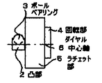
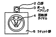
(イ)ラチェット部(5)の回転ダイヤル(4)の中心軸(6)に対して凸部(2)等の接続部の位置を直角方向又は直角方向以外の中心軸(6)上を除いた方向に配置した事を特徴とするフレキシブル固定具は、既存のラチェット工具同様に回転ダイヤル(4)を切り替える事により、回転方向を替える事が出来る機能を保持するものとする。
(ロ)ラチェット部(5)に設けられた凸部(2)内に収められたボール・ベアリング(3)は、凸部(2)内に収められたスプリング等の反発力を利用して、凸部(2)と対の凹部(12)に内に挿入され固定される。又凸部(2)以外の接続方法としては、対の凹凸部を入れ替えた凹部又は螺合又は嵌合又はその他の接続方法でも接続可能である。
(ハ)ラチェット部(5)に設けられた凸部(2)内に収められたボール・ベアリング(3)の材質は、硬質材以外に柔軟質材に変更する事が出来る。その時に凸部(2)内に収められたスプリング等の反発力を利用する代わりに、柔軟材の持つ反発力、摩擦力をも考慮する事が出来る。
(ニ)ラチェット部(5)に設けられた回転部ダイヤル(4)は左傾斜位置及び右傾斜位置及び中立位置を有し、回転部ダイヤル(4)が左傾斜位置で凸部(2)が左方向に回転可能になり、回転部ダイヤル(4)が右傾斜位置で凸部(2)が右方向に回転可能になり、回転部ダイヤル(4)が中立位置で凸部(2)を固定させる事が出来る。This will be described below with reference to FIGS.
(B) The position of the connecting portion such as the convex portion (2) is perpendicular to the central axis (6) of the rotary dial (4) of the ratchet portion (5) except on the central axis (6) other than the perpendicular direction. The flexible fixture characterized by being arranged in a different direction shall retain the function of changing the direction of rotation by switching the rotary dial (4) in the same manner as the existing ratchet tool.
(B) The ball bearing (3) housed in the convex part (2) provided in the ratchet part (5) uses the repulsive force of a spring or the like contained in the convex part (2), The protrusion (2) and the pair of recesses (12) are inserted and fixed inside. Further, as a connection method other than the convex portion (2), the connection can be made by a concave portion in which a pair of concave and convex portions are exchanged, screwing, fitting, or other connection methods.
(C) The material of the ball bearing (3) housed in the convex part (2) provided in the ratchet part (5) can be changed to a flexible material other than the hard material. At that time, instead of using the repulsive force of the spring or the like housed in the convex portion (2), the repulsive force and frictional force of the flexible material can be considered.
(D) The rotating part dial (4) provided in the ratchet part (5) has a left inclined position, a right inclined position, and a neutral position, and the rotating part dial (4) is a left inclined position and the convex part (2) is Rotating part dial (4) can be rotated to the right when the rotating part dial (4) is tilted to the right, and the protruding part (2) can be rotated to the right. You can make it.
以下図4を用いて説明する。
既存のフレキシブルパイプ同様に柔軟性が有り、自由に角度調節出来る機能を保持するフレキシブルパイプ(1)の端末に設けられた凹部(12)とラチェット部(5)に設けられた凸部(2)を接続する。又凹部(12)以外の接続方法としては、対の凹凸部を入れ替えた凸部又は螺合又は嵌合又はその他の接続方法でも接続可能である。This will be described below with reference to FIG.
Convex part (12) provided at the end of the flexible pipe (1) and the convex part (2) provided in the ratchet part (5), which is flexible like the existing flexible pipe and retains the function of adjusting the angle freely. Connect. Moreover, as a connection method other than the concave portion (12), the connection can also be made by a convex portion in which a pair of concave and convex portions are replaced, screwing, fitting, or other connection methods.
以下図5を用いて説明する。
支持体(10)の一方の端末に設けられた接続部とラチェット部(5)に設けられた接続部を螺合接続し、支持体(10)の他方の端末に設けられた接続部とツマミ部(11)に設けられた接続部を螺合接続する。螺合接続以外にも嵌合又はその他の接続方法で接続する事が出来る。洗濯ハサミ的機能を有するツマミ部(11)より、例えば自転車のハンドル、傘等、任意の物を掴み、固定する事が出来る。This will be described below with reference to FIG.
A connection portion provided on one end of the support body (10) and a connection portion provided on the ratchet portion (5) are screwed together, and a connection portion and a knob provided on the other end of the support body (10) are connected. The connection part provided in the part (11) is screwed and connected. In addition to threaded connection, connection can be achieved by fitting or other connection methods. An arbitrary object such as a bicycle handle or an umbrella can be grasped and fixed from the knob portion (11) having a washing scissors function.
以下図6を用いて説明する。
支持体(10)の一方の端末に設けられた接続部とラチェット部(5)に設けられた接続部を螺合接続し、支持体(10)の他方の端末に設けられた接続部と球体部(7)に設けられた接続部を螺合接続する。螺合接続以外にも嵌合又はその他の接続方法で接続する事が出来る。更に球体具(16)は球体部(7)を球体部受け皿(9)に挿入し、固定ハンドル(8)により、角度調節及び固定させる事が出来る。これにより角度調節の自由度を広げる事が出来る。This will be described below with reference to FIG.
A connection portion provided on one end of the support body (10) and a connection portion provided on the ratchet portion (5) are screwed together, and a connection portion and a sphere provided on the other end of the support body (10). The connection part provided in the part (7) is screwed. In addition to threaded connection, connection can be achieved by fitting or other connection methods. Further, the sphere tool (16) can be adjusted in angle and fixed by inserting the sphere portion (7) into the sphere portion tray (9) and using the fixed handle (8). Thereby, the freedom degree of angle adjustment can be expanded.
以下図7を用いて説明する。
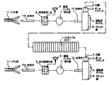
(イ)支持体(10)の一方の端末に設けられた接続部とラチェット部(5)に設けられた接続部を螺合接続し、支持体(10)の他方の端末に設けられた接続部と球体部(7)に設けられた接続部を螺合接続する。螺合接続以外にも嵌合又はその他の接続方法で接続する事が出来る。更に球体部(7)を球体部受け皿(9)に挿入し、固定ハンドル(8)により、角度調節及び固定させる事が出来る球体具(16)は、これにより角度調節の自由度を広げる事が出来る。更に支持体(10a)の一方の端末に設けられた接続部と球体部受け皿(9)に設けられた接続部を螺合接続し、支持体(10a)の他方の端末に設けられた接続部とツマミ部(11)に設けられた接続部を螺合接続する。螺合接続以外にも嵌合又はその他の接続方法で接続する事が出来る。これにより、例えば自転車のハンドル、傘等、任意の物を掴み、固定する事が出来る。
(ロ)フレキシブルパイプ(1)の両端末の凹部(12)にラチェット部(5)の凸部(2)を接続し、支持体(10)、球体具(16)、支持体(10a)、ツマミ部(11)を順に接続する事で、例えば、一方のツマミ部(11)に自転車のハンドル又は、サドル部、荷台部、乳母車、車椅子、杖、台車、屋外テーブル、等々の任意の固定場所に装着し、他方のツマミ部(11)に傘を固定する事によって傘固定具として利用出来る。
(ハ)フレキシブルパイプ(1)の構造を先細りの伸縮可能なアンテナ方式にする事でパイプ長を調整出来る。
(ニ)フレキシブルパイプ(1)の端末の一方を対の凹部又は凸部に変更する事で、フレキシブルパイプ(1)と連結する事で、パイプの延長が出来る。This will be described below with reference to FIG.
(A) A connection provided on one end of the support (10) and a connection provided on the ratchet (5) are screwed together to provide a connection provided on the other end of the support (10). And the connecting portion provided on the spherical portion (7) are screwed together. In addition to threaded connection, connection can be achieved by fitting or other connection methods. Furthermore, the sphere tool (16), in which the sphere part (7) can be inserted into the sphere part tray (9) and the angle can be adjusted and fixed by the fixed handle (8), can increase the degree of freedom of angle adjustment. I can do it. Furthermore, the connection part provided in one terminal of the support body (10a) and the connection part provided in the spherical body tray (9) are screwed together, and the connection part provided in the other terminal of the support body (10a). And the connecting portion provided in the knob portion (11) are screwed together. In addition to threaded connection, connection can be achieved by fitting or other connection methods. Thereby, for example, an arbitrary object such as a bicycle handle or an umbrella can be grasped and fixed.
(B) The convex part (2) of the ratchet part (5) is connected to the concave part (12) of both ends of the flexible pipe (1), the support body (10), the ball tool (16), the support body (10a), By connecting the knob part (11) in order, for example, one of the knob parts (11) can be attached to any handle such as a bicycle handle, saddle part, cargo bed part, baby carriage, wheelchair, cane, carriage, outdoor table, etc. And can be used as an umbrella fixing tool by fixing the umbrella to the other knob portion (11).
(C) The pipe length can be adjusted by making the flexible pipe (1) structure into a tapered and extendable antenna system.
(D) By changing one end of the flexible pipe (1) to a pair of concave or convex portions, the pipe can be extended by connecting to the flexible pipe (1).
1 フレキシブルパイプ
2 凸部
3 ボール・ベアリング
4 回転部ダイヤル
5 ラチェット部
6 中心軸
7 球体部
8 固定ハンドル
9 球体部受け皿
10 支持体
10a 支持体
11 ツマミ部
12 凹部
13 自転車ハンドル
14 傘
15 傘の柄
16 球体具DESCRIPTION OF SYMBOLS 1
Claims (5)
Priority Applications (1)
| Application Number | Priority Date | Filing Date | Title |
|---|---|---|---|
| JP2004341206A JP2006125613A (en) | 2004-10-26 | 2004-10-26 | Flexible fixture |
Applications Claiming Priority (1)
| Application Number | Priority Date | Filing Date | Title |
|---|---|---|---|
| JP2004341206A JP2006125613A (en) | 2004-10-26 | 2004-10-26 | Flexible fixture |
Publications (2)
| Publication Number | Publication Date |
|---|---|
| JP2006125613A true JP2006125613A (en) | 2006-05-18 |
| JP2006125613A5 JP2006125613A5 (en) | 2007-12-06 |
Family
ID=36720538
Family Applications (1)
| Application Number | Title | Priority Date | Filing Date |
|---|---|---|---|
| JP2004341206A Pending JP2006125613A (en) | 2004-10-26 | 2004-10-26 | Flexible fixture |
Country Status (1)
| Country | Link |
|---|---|
| JP (1) | JP2006125613A (en) |
-
2004
- 2004-10-26 JP JP2004341206A patent/JP2006125613A/en active Pending
Similar Documents
| Publication | Publication Date | Title |
|---|---|---|
| JP5002649B2 (en) | Protective helmet, especially bicycle helmet | |
| US8894316B2 (en) | Adjustable joint for microphone | |
| US20030110797A1 (en) | Gravity balancing ring | |
| EP1210210A4 (en) | Handtool with rotatable arms | |
| US7237931B2 (en) | Orientation adjustable lamp | |
| CA2476975A1 (en) | Steering damper device | |
| JP2006308072A (en) | Constant pressure ball joint | |
| JP2006125613A (en) | Flexible fixture | |
| US6270238B1 (en) | Durable pivotal connecting device for table lamp | |
| US20100188764A1 (en) | Adjustable rear view mirror | |
| CN111279126B (en) | Fastening unit for fixing a lamp on a support | |
| US20060226330A1 (en) | Bar support rack | |
| DE60228719D1 (en) | BLOCK ROLL | |
| KR200410390Y1 (en) | Supporting tool for revolution mirror | |
| CN205757683U (en) | A kind of universal umbrella handle and the Universal umbrella with this umbrella handle | |
| KR950004420Y1 (en) | Mirror | |
| CN212657630U (en) | Lamp body that can multi-angle was adjusted | |
| WO2004091971A3 (en) | A breakaway bus mount system to hold mirror supporting shaft | |
| KR200225072Y1 (en) | Angular adjustable supporter | |
| CN210797740U (en) | Shower rod with angle adjusting function | |
| CN210122979U (en) | Angle fixing clamp seat easy to steer | |
| JP3109551U (en) | Adjustable motorcycle handle | |
| JP3130782U (en) | Infant umbrella holder | |
| CN202593756U (en) | Bicycle seat | |
| KR20080000419U (en) | Multipurpose supporting device |
Legal Events
| Date | Code | Title | Description |
|---|---|---|---|
| A521 | Written amendment |
Free format text: JAPANESE INTERMEDIATE CODE: A523 Effective date: 20071022 |
|
| A621 | Written request for application examination |
Free format text: JAPANESE INTERMEDIATE CODE: A621 Effective date: 20071022 |
|
| RD03 | Notification of appointment of power of attorney |
Free format text: JAPANESE INTERMEDIATE CODE: A7423 Effective date: 20071022 |
|
| A131 | Notification of reasons for refusal |
Free format text: JAPANESE INTERMEDIATE CODE: A131 Effective date: 20091027 |
|
| A977 | Report on retrieval |
Free format text: JAPANESE INTERMEDIATE CODE: A971007 Effective date: 20091029 |
|
| A02 | Decision of refusal |
Free format text: JAPANESE INTERMEDIATE CODE: A02 Effective date: 20100302 |