JP2006099558A - Production navigation system and navigation terminal - Google Patents
Production navigation system and navigation terminal Download PDFInfo
- Publication number
- JP2006099558A JP2006099558A JP2004286564A JP2004286564A JP2006099558A JP 2006099558 A JP2006099558 A JP 2006099558A JP 2004286564 A JP2004286564 A JP 2004286564A JP 2004286564 A JP2004286564 A JP 2004286564A JP 2006099558 A JP2006099558 A JP 2006099558A
- Authority
- JP
- Japan
- Prior art keywords
- work
- navigation
- screen
- production
- product
- Prior art date
- Legal status (The legal status is an assumption and is not a legal conclusion. Google has not performed a legal analysis and makes no representation as to the accuracy of the status listed.)
- Pending
Links
Images


Classifications
-
- Y—GENERAL TAGGING OF NEW TECHNOLOGICAL DEVELOPMENTS; GENERAL TAGGING OF CROSS-SECTIONAL TECHNOLOGIES SPANNING OVER SEVERAL SECTIONS OF THE IPC; TECHNICAL SUBJECTS COVERED BY FORMER USPC CROSS-REFERENCE ART COLLECTIONS [XRACs] AND DIGESTS
- Y02—TECHNOLOGIES OR APPLICATIONS FOR MITIGATION OR ADAPTATION AGAINST CLIMATE CHANGE
- Y02P—CLIMATE CHANGE MITIGATION TECHNOLOGIES IN THE PRODUCTION OR PROCESSING OF GOODS
- Y02P90/00—Enabling technologies with a potential contribution to greenhouse gas [GHG] emissions mitigation
- Y02P90/02—Total factory control, e.g. smart factories, flexible manufacturing systems [FMS] or integrated manufacturing systems [IMS]
Abstract
Description
本発明は、製品の組立を行う手順にしたがって使用すべき部品を指示して、作業者に対し作業のナビゲーションを行う技術に関する。 The present invention relates to a technique for instructing parts to be used in accordance with a procedure for assembling a product and performing work navigation for an operator.
近年、製品の生産を市場動向に迅速に適合させるために、多品種少量生産、機種の頻繁な切り換え、製品仕様の頻繁な変更等が生産現場において求められている。このため、製品の生産形態が、多くの作業者が工程を順次分担して流れ作業を行うライン生産方式から、一人の作業者が組立工程の全てを行って製品を組み立てるセル生産方式が採用されつつある。 In recent years, in order to quickly adapt the production of products to market trends, there are demands in production sites for high-mix low-volume production, frequent switching of models, frequent changes in product specifications, and the like. For this reason, the cell production method, in which a single worker performs all the assembly processes and assembles the product, is adopted instead of the line production method in which many workers share the process sequentially with the production form of the product. It's getting on.
このセル生産方式では、各作業者が組立てに必要なすべての工程について習熟していることが要求される。そのため、製品を新たに組み立てる場合、各作業者は、すべての作業手順と使われる部品とを把握することが必要となる。すなわち、各作業者は、作業手順書に基づいて、作業手順、方法、留意点、および、使われる部品、工具等を全て理解しなければならない。しかし、この方式では、一人の作業者が受け持つ工程数が多いため、作業自体はもとより、作業のための学習が、各作業者にとって非常に大きな負担になる。また、機種の切替えの場合にも、別の作業手順書を理解する必要が生じ、同様の問題が起きる。 In this cell production system, each worker is required to be familiar with all the processes necessary for assembly. Therefore, when a product is newly assembled, each worker needs to grasp all work procedures and parts to be used. That is, each worker must understand all of the work procedure, method, points to be noted, and parts, tools, etc. used based on the work procedure manual. However, in this method, since one worker has a large number of processes, learning for the work as well as the work itself becomes a very heavy burden on each worker. Also, when switching between models, it is necessary to understand another work procedure manual, and the same problem occurs.
このような問題を改善するため、次に行うべき組立工程において、どの部品をどのように組み立てるのかについて表示装置において画面表示することが提案されている(特許文献1)。 In order to improve such a problem, it has been proposed to display on the display device which component is to be assembled in the assembly process to be performed next (Patent Document 1).
また、作業ラインに沿って複数の単位作業を順番に行って一連の全体作業を完成する作業システムが提案されている(特許文献2)。このシステムにおいては、前記全体作業を複数の作業区分に分割し、各作業区分で行われる単位作業を作業順序にしたがって表示する作業指示手段を設け、各単位作業が実行されたことを検出する検出手段を設け、前記全体作業を任意の作業区分に分割して設定する入力手段を備えている。そして、この入力手段により設定された各作業区分内で、この作業区分に含まれる単位作業について、前記作業指示手段により指示した単位作業が実行されたことを前記検出手段により検出するとともに前記作業指示手段により実行すべき単位作業を順番に繰り返して表示する。 In addition, there has been proposed a work system that completes a series of overall work by sequentially performing a plurality of unit works along a work line (Patent Document 2). In this system, the whole work is divided into a plurality of work sections, work instruction means for displaying the unit work performed in each work section according to the work order is provided, and detection for detecting that each unit work is executed And an input means for dividing the entire work into arbitrary work sections for setting. Then, within each work category set by the input means, the unit means instructed by the work instruction means is detected by the detection means for the unit work included in the work category, and the work instruction The unit operations to be executed by the means are displayed repeatedly in order.
特許文献1に示される技術では、作業者に対して作業の手順の表示と監視とが行われる。また、作業の進捗状況が管理される。しかし、特許文献1では、特定の作業位置における作業の手順の表示と監視と進捗管理とが行われるにすぎない。例えば、生産には、複数の部品が用いられるが、それらについてその使用順を考慮して表示することについてまでは対応できていない。この点は、特許文献2についても同様である。
In the technique disclosed in
本発明の目的は、複数の部品を使用する場合にも、作業の手順を誤ることなく的確に作業できるよう表示することができる技術を提供することにある。 An object of the present invention is to provide a technique capable of displaying so as to be able to work accurately without mistakes in the work procedure even when a plurality of parts are used.
本願の第1の発明によれば、
ネットワークを介して接続される複数のナビゲーション端末を備え、各ナビゲーション端末において生産を支援する生産ナビゲーションシステムであって、
前記複数のナビゲーション端末は、それぞれ前記製品の生産の流れに沿って配置され、
前記各ナビゲーション端末は、
生産すべき製品の生産作業手順、および、使用する部品を、画面に表示するためのナビゲーション画面データを記憶する手段と、
前記記憶する手段から、前記ナビゲーション画面データを読み出して、生産すべき製品の生産作業手順を、使用する部品と共に、表示装置に表示させるナビゲーション画面表示手段と、を備え、
前記ナビゲーション画面表示手段は、前記作業手順と、使用する部品とについて、画像とテキストにより表示すること
を特徴とするナビゲーションシステムが提供される。
According to the first invention of the present application,
A production navigation system comprising a plurality of navigation terminals connected via a network and supporting production in each navigation terminal,
Each of the plurality of navigation terminals is arranged along a production flow of the product,
Each of the navigation terminals is
Means for storing the production work procedure of the product to be produced and the navigation screen data for displaying the parts to be used on the screen;
A navigation screen display means for reading the navigation screen data from the storage means and displaying a production work procedure of a product to be produced together with parts to be used on a display device;
The navigation screen display means displays the work procedure and the parts to be used by an image and text. A navigation system is provided.
第2の発明によれば、
ネットワークを介して接続される複数のナビゲーション端末を備え、各ナビゲーション端末において生産を支援する生産ナビゲーションシステムであって、
前記複数のナビゲーション端末は、それぞれ前記製品の生産の流れに沿って配置され、
前記各ナビゲーション端末は、
生産すべき製品の生産作業手順、使用する部品、および、使用する工具を、画面に表示するためのナビゲーション画面データを記憶する手段と、
前記記憶する手段から、前記ナビゲーション画面データを読み出して、生産すべき製品の生産作業手順を、使用する部品および使用する工具と共に、表示装置に表示させるナビゲーション画面表示手段と、を備え、
前記ナビゲーション画面表示手段は、前記作業手順、使用する部品、および、使用する工具について、画像とテキストにより表示すること
を特徴とするナビゲーションシステムが提供される。
According to the second invention,
A production navigation system comprising a plurality of navigation terminals connected via a network and supporting production in each navigation terminal,
Each of the plurality of navigation terminals is arranged along a production flow of the product,
Each of the navigation terminals is
Means for storing navigation screen data for displaying on the screen the production work procedure of the product to be produced, the parts to be used, and the tools to be used;
A navigation screen display means for reading the navigation screen data from the storage means and displaying a production work procedure of a product to be produced on a display device together with parts to be used and tools to be used;
The navigation screen display means provides the navigation system characterized by displaying the work procedure, the parts to be used, and the tools to be used with images and text.
第3の発明によれば、
生産を支援するためのナビゲーション端末であって、
生産すべき製品の生産作業手順、使用する部品を画面に表示するためのナビゲーション画面データを記憶する手段と、
前記記憶する手段から、前記ナビゲーション画面データを読み出して、生産すべき製品の作業手順を、使用する部品と共に、表示装置に表示させるナビゲーション画面表示手段と、を備え、
前記ナビゲーション画面表示手段は、前記作業手順と、使用する部品とについて、画像とテキストにより表示すること
を特徴とするナビゲーション端末が提供される。
According to the third invention,
A navigation terminal for supporting production,
Means for storing the production work procedure of the product to be produced and navigation screen data for displaying the parts to be used on the screen;
The navigation screen display means for reading the navigation screen data from the storing means and displaying the work procedure of the product to be produced together with the parts to be used on a display device,
The navigation screen display means provides a navigation terminal characterized in that the work procedure and the parts to be used are displayed as images and text.
第4の発明によれば、
生産を支援するためのナビゲーション端末であって、
生産すべき製品の生産作業手順、使用する部品、および、使用する工具を画面に表示するためのナビゲーション画面データを記憶する手段と、
前記記憶する手段から、前記ナビゲーション画面データを読み出して、生産すべき製品の生産作業手順を、使用する部品および使用する工具と共に、表示装置に表示させるナビゲーション画面表示手段と、を備え、
前記ナビゲーション画面表示手段は、前記作業手順と、使用する部品とについて、画像とテキストにより表示すること
を特徴とするナビゲーション端末が提供される。
According to the fourth invention,
A navigation terminal for supporting production,
Means for storing the production work procedure of the product to be produced, the parts to be used, and the navigation screen data for displaying the tools to be used on the screen;
A navigation screen display means for reading the navigation screen data from the storage means and displaying a production work procedure of a product to be produced on a display device together with parts to be used and tools to be used;
The navigation screen display means provides a navigation terminal characterized in that the work procedure and the parts to be used are displayed as images and text.
第5の発明によれば、
生産を支援する方法であって、
生産すべき製品の生産作業手順、使用する部品を画面に表示するためのナビゲーション画面データを記憶装置に記憶させておき、
前記記憶装置から、前記ナビゲーション画面データを読み出して、生産すべき製品の作業手順を、使用する部品と共に、表示装置に表示させ、
前記ナビゲーション画面表示は、前記作業手順と、使用する部品とについて、画像とテキストにより表示すること
を特徴とする生産を支援する方法が提供される。
According to the fifth invention,
A method of supporting production,
The production work procedure of the product to be produced and the navigation screen data for displaying the parts to be used on the screen are stored in the storage device,
The navigation screen data is read from the storage device, and the work procedure of the product to be produced is displayed on the display device together with the parts to be used.
The navigation screen display provides a production support method characterized by displaying the work procedure and the parts to be used with images and text.
第6の発明によれば、
生産を支援する方法であって、
生産すべき製品の生産作業手順、使用する部品、および、使用する工具を画面に表示するためのナビゲーション画面データを記憶装置に記憶させておき、
前記記憶装置から、前記ナビゲーション画面データを読み出して、生産すべき製品の生産作業手順を、使用する部品および使用する工具と共に、表示装置に表示させ、
前記ナビゲーション画面表示は、前記作業手順、使用する部品、および、使用する工具について、画像とテキストにより表示すること
を特徴とする生産を支援する方法が提供される。
According to the sixth invention,
A method of supporting production,
The navigation screen data for displaying the production work procedure of the product to be produced, the parts to be used, and the tools to be used on the screen are stored in the storage device,
The navigation screen data is read from the storage device, and the production work procedure of the product to be produced is displayed on the display device together with the parts to be used and the tools to be used.
The navigation screen display provides a method for supporting production, characterized in that the work procedure, parts to be used, and tools to be used are displayed as images and text.
これらの発明によれば、複数の部品を使用する場合にも、作業の手順を誤ることなく的確に作業できるよう表示することができる。 According to these inventions, even when a plurality of parts are used, it is possible to display so that the work can be performed accurately without mistakes in the work procedure.
以下、本発明の実施形態について、図面を参照して説明する。
<第1の実施形態>
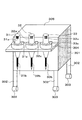
図1は、本発明の第1の実施形態に係る生産ナビゲーションシステムが設置される生産ラインの概要を示す説明図である。図1に、生産ラインL1〜Lnが設けられている工場100を示す。図1では、表現の制約上、中間のラインを省いて、ラインL1とLnとを示す。ライン数は、1からnまで必要に応じて適宜設定することができる。
Hereinafter, embodiments of the present invention will be described with reference to the drawings.
<First Embodiment>
FIG. 1 is an explanatory diagram showing an outline of a production line in which a production navigation system according to the first embodiment of the present invention is installed. FIG. 1 shows a
各生産ラインL1〜Lnは、それぞれ工程系列が、複数の作業ポジションP1からPm(図1の例では、P1からP5)に分割されている。言い換えると、各生産ラインL1からLnに、工程系列に沿って複数の作業ポジションP1からP5が設けられている。そして、基本的には、各作業ポジションP1からP5に、作業員Wrが一人ずつ配置される。ここで、作業ポジションとは、作業員が1乃至複数工程を担当して生産を行う場所乃至位置を意味する。 In each of the production lines L1 to Ln, the process sequence is divided into a plurality of work positions P1 to Pm (P1 to P5 in the example of FIG. 1). In other words, each of the production lines L1 to Ln is provided with a plurality of work positions P1 to P5 along the process sequence. Basically, one worker Wr is arranged at each work position P1 to P5. Here, the work position means a place or position where the worker performs production in charge of one or more processes.
作業ポジションの数mは、生産すべき対象の工程数、作業難易度、想定される必要作業員数等に応じて適宜設定される。図1の場合は、mが5であり、P1からP5の5ポジションとなっている。これは説明の便宜上定めたものである。各作業ポジションP1からP5には、その生産ラインが受け持つ工程系列から、それぞれ1乃至複数工程が割り振られる。例えば、製品が100工程の工程系列を経て完成する場合に、各作業ポジションP1からP5に、全体として100工程になるように、複数の工程を割り当てる。この場合、各作業ポジションの分担する工程数は、後述するように、生産ラインの状況に応じて適宜定めることができるので、同一になるとは限らない。 The number m of work positions is appropriately set according to the number of processes to be produced, the degree of work difficulty, the expected number of required workers, and the like. In the case of FIG. 1, m is 5, and there are 5 positions from P1 to P5. This is determined for convenience of explanation. Each work position P1 to P5 is assigned one to a plurality of processes from the process sequence that the production line is responsible for. For example, when a product is completed through a process sequence of 100 processes, a plurality of processes are assigned to each work position P1 to P5 so that there are 100 processes as a whole. In this case, as will be described later, the number of processes assigned to each work position can be determined as appropriate according to the situation of the production line, and is not necessarily the same.
作業ポジション数、各作業ポジションにおいて受け持つべき工程数等は、その生産ラインが受け持つ製品の工程系列に応じて、また、その生産ラインを受け持つ各作業員の習熟度等を考慮して、生産ライン毎に柔軟に定めることができる。従って、各生産ラインが異なる製品を生産する場合はもとより、同じ製品を同じ工程系列により生産する場合であっても、生産ラインによって異なる作業ポジション数となること、分担する工程が異なること等があり得る。 The number of work positions, the number of processes to be handled at each work position, etc. depends on the process series of the products handled by the production line and the proficiency level of each worker responsible for the production line. Can be determined flexibly. Therefore, not only when each production line produces a different product, even when the same product is produced by the same process sequence, the number of work positions may differ depending on the production line, and the shared processes may differ. obtain.
また、各作業ポジションにおいて分担する工程については予め定められている。しかし、本実施形態では、上流側において作業の遅れ等が発生した場合、また、下流側において手空きが生じた場合、下流側作業ポジションの作業者が上流側作業ポジションにおける作業者の作業の残り分を引き受けるように、工程の分担を変更することができる。逆に、下流側において作業遅れが発生した場合、上流側作業ポジションにおいて、現在の仕掛品の組立てについて、下流側の工程まで引き受けるように、工程の分担を変更することができる。このように、作業の進捗状況に応じて工程分担を柔軟に変更することにより、全体として、作業効率を上げることができる。 In addition, the process shared at each work position is determined in advance. However, in the present embodiment, when a work delay or the like occurs on the upstream side, or when a vacancy occurs on the downstream side, the worker at the downstream work position remains the work of the worker at the upstream work position. The share of the process can be changed to accept the share. On the contrary, when a work delay occurs on the downstream side, the division of the process can be changed so that the current work-in-process assembly is accepted to the downstream process at the upstream work position. Thus, the work efficiency can be improved as a whole by flexibly changing the process assignment according to the progress of the work.
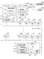
各作業ポジションP1からP5には、作業者のための作業エリアが設けられる。図1の場合を例に挙げると、各作業ポジションP1からP5に、その場所において作業に必要な機器等が配置される。すなわち、工程毎の作業内容および手順、使用部品、使用工具等を表示して、作業ガイドを行うナビゲーション端末10と、その作業ポジションにおいて用いられる複数種の部品を配置する部品配置装置20と、その作業ポジションにおいて用いられる工具を配置する工具装置30と、生産されるべき部品等の組み付けが行われる仕掛品が置かれる移動作業台70とが、各作業ポジションP1からP5に配置される。なお、図1では、表記を簡略化するため、一部の作業ポジションについてのみ機器類を図示している。
A work area for the worker is provided at each work position P1 to P5. Taking the case of FIG. 1 as an example, devices and the like necessary for work are arranged at the work positions P1 to P5. That is, a
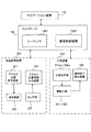
ナビゲーション端末10は、図2に示すように、ネットワーク60に接続される。また、各ナビゲーション端末10は、固有の識別子を有する。図2では、10Aから10Jの符号により区別して示す。従って、この識別子をアドレスの一部に含むことにより、ネットワーク60を介して互いに通信を行うことができる。また、図1に示すように、管理サーバ50との間で、また、部品の補給を管理する補給端末80との間でも通信を行うことができる。また、ナビゲーション端末10Aには、コントローラ18Aを介して部品配置装置20Aと、工具装置30Aとが接続される。この構成は、他のナビゲーション端末10Bから10Jについても同様である。
The
コントローラ18は、シーケンサ181と、外部との通信を制御する通信制御装置182とを有する(図7参照)。シーケンサ181は、ナビゲーション端末10からの指示、操作に基づいて、部品配置装置20および工具装置30の動作を制御する。また、部品配置装置20および工具装置30から送られるセンサ情報の収集を行って、対応するナビゲーション端末10に送る。
The
移動作業台70は、作業ポジションに固定配備されるものではない。それぞれの作業ポジションP1に割り当てられているすべての工程についての作業が終わると、その次の作業ポジションに移動される。すなわち、移動作業台70は、その上に置かれる仕掛品をこれから作業が行われるべき作業ポジションに入力させる移動体として機能する。そして、作業中のポジションにおいて、仕掛品に対する各種工程での作業を行わせる作業台として機能する。すなわち、各作業者は、ナビゲーション端末10の指示に従って、必要な部品を部品配置装置20から取り出し、工具装置30にあるトルクドライバ等の工具を用い、移動作業台70において、組立、調整作業等を行う。さらに、作業が終わった作業ポジションから、仕掛品を出力させる移動体として機能する。各生産ラインL1からLnにおける作業最終ポジションP5(図1の場合)から出力される場合、その生産ラインでの工程系列に属するすべての工程が終了したことになる。
The movable work table 70 is not fixedly arranged at the work position. When work for all processes assigned to each work position P1 is completed, the work position is moved to the next work position. That is, the moving work table 70 functions as a moving body that allows a work in progress placed thereon to be input to a work position where work is to be performed. Then, it functions as a work table for performing work in various processes on work-in-progress at the work position. That is, each worker takes out necessary parts from the
本実施形態では、ナビゲーション端末10が、それが置かれているラインでのすべての工程系列についての生産ナビゲーションが行えるよう、他のナビゲーション端末における作業についても、作業ガイダンスのための情報を記憶している。そして、それが置かれている作業ポジションでの各製品の進捗状況を示す情報を保持している。作業進捗状況の情報は、例えば、作業者が作業を終了する毎に、当該作業ポジションのナビゲーション端末に記録される他、他のナビゲーション端末および管理サーバ50に送られる。これにより、製品の進捗状況を示す情報がラインにおいて共有されることとなる。この結果、作業者は、どのナビゲーション端末10からでも、ある製品の組立作業のガイドを受けることができる。従って、部品が用意されていることを条件として、いずれの作業ポジションにおいても、仕掛品の組立作業を再開することができる。ただし、部品の配置の関係から、隣接する作業ポジションの範囲内において作業を再開できるようにすることが現実的であろう。一方、本実施形態では、生産方式を一人セル生産方式に切り替えることが柔軟に行えるということでもある。
In this embodiment, the
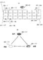
部品配置装置20は、生産に用いられる複数種の部品を配置するための装置であって、例えば、図5(A)に模式的に示すような部品棚25を有する。部品棚25は、複数のサブ領域25−1から25−24に区画され、これらのサブ領域25−1から25−24に複数種の部品が配置される部品配置領域を構成する、また、この部品配置装置20は、図7に示すように、この部品棚25におけるいずれのサブ領域から部品を取り出すかのアクセス位置を特定するためのアクセス位置指示装置21と、当該サブ領域対応に設けられ、各サブ領域を指示するための発光ダイオード等の指示器群26と、各サブ領域について、部品を取得するために実際にアクセスしたことを検知するセンサ群27と、センサ27群の検知信号を基に、アクセス位置情報を出力するアクセス位置情報出力装置22と、を有する。
The
図5(A)に示す部品棚25は、24箇所のサブ領域25−1から25−24の区画に分けられ、それぞれに指示器26−1から26−24が配置され、いずれのサブ領域から部品を取るべきかを、作業者に対して視覚的に指示できるようになっている。また、当該部品棚に、取り出すべき部品が存在することを示すため、棚自体にも、発光ダイオード等の指示器26−0が設けられている。
The
また、本実施形態では、指示器26−1から26−24は、例えば、赤と緑の、少なくとも2色が選択的に発光できる素子が用いられている。具体的には、図5(B)に示すように、指示器26−1から26−24は、取るべき部品の取得前に、該当する指示器が、赤色発光により取るべき位置を教え(指示モード)、取得後に、一定時間、例えば、10秒ほど、緑色発光し(確認モード)、その後、消灯する(待機モード)という順にモードが遷移する構成としてある。このようにすることにより、作業者が確かに部品を取り出したということを確認できる利点がある。このモード遷移は、コントローラ18のシーケンサ181により制御される。
In the present embodiment, the indicators 26-1 to 26-24 are elements that can selectively emit at least two colors of red and green, for example. Specifically, as shown in FIG. 5 (B), the indicators 26-1 to 26-24 teach (instruct) the position that the corresponding indicator should take by red light emission before acquiring the parts to be taken. Mode), after acquisition, the mode changes in the order of emitting green light (confirmation mode) for about 10 seconds, for example, and then turning off (standby mode). By doing in this way, there exists an advantage which can confirm that an operator surely took out components. This mode transition is controlled by the
図5(A)に示す例では、既に部品の取り出しが済んだ後のサブ領域の指示器26−17が緑色発光している状態で、次に部品を取り出すべき、隣接するサブ領域の指示器26−18が赤色発光している状態を示す。もちろん、指示器26−17と指示器26−18の発光タイミングは、重ならなくてもよい。 In the example shown in FIG. 5A, in the state where the indicator 26-17 in the sub area after the part has already been taken out emits green light, the indicator in the adjacent sub area where the part should be taken out next. 26-18 shows the state of emitting red light. Of course, the light emission timings of the indicator 26-17 and the indicator 26-18 may not overlap.
2色の発光が選択的に可能な素子としては、例えば、それぞれの色の発光を行う発光ダイオードチップを一体的にモールドして、それぞれについて、外部から駆動電流を選択的に供給して選択的に発光させる構成としたものを用いることができる。もちろん、はじめから各色の個別の発光素子を用いてもよい。さらに、内部に、スイッチ回路を搭載し、外部からは、駆動電流と、スイッチ回路の選択信号とを供給する構成とすることもできる。発光素子の発光は、コントローラ18により制御される。
As an element that can selectively emit light of two colors, for example, a light emitting diode chip that emits light of each color is molded integrally, and a driving current is selectively supplied from the outside to selectively select each of the elements. A light emitting device that emits light can be used. Of course, individual light-emitting elements of each color may be used from the beginning. Further, a switch circuit may be mounted inside, and a drive current and a switch circuit selection signal may be supplied from the outside. The light emission of the light emitting element is controlled by the
指示器26−1から26−24は、複数色ではなく、単色による指示であってもよい。この場合、作業者に、いずれかの指示器が点灯すると、取るべき位置を指示している状態となり、作業者がアクセスしたことがセンサ群27によって検知された後、消灯するという構成とすることができる。また、取るべき位置を指示する場合に、点滅させ、アクセスがあった後、一定時間、点滅しない点灯状態とし、その後、消灯する構成とすることもできる。
The indicators 26-1 to 26-24 may be instructions of a single color instead of a plurality of colors. In this case, when any indicator is turned on to the worker, the position to be taken is instructed, and after the
センサ群27は、領域25−1から25−24のいずれにアクセスがあったかを検出する。具体的には、各領域25−1から25−24に、センサ27−1から27−24を配置し、例えば、作業者の手がその領域に進入すると、それを検知して、信号を出力する。この種のセンサとして、例えば、光電センサ、赤外線センサ、静電容量変化センサ等を用いることができる。本実施形態では、光電センサを用いている。光電センサを用いる場合には、発光素子とそれからの光を受光する受光素子とを組み合わせたものを用いて、人の手等の物体が発光素子からの光を遮る状態を受光素子により検出することにより、当該領域へのアクセスを検出する。図5Aでは、表記を簡単にするため、発光素子側のみ示しているが、各サブ領域を構成する部品棚の対向する壁面には、それぞれ発光素子と対向する受光素子が配置されている。従って、人の手が棚のある領域に進入すると、状態としておき、光電センサとしては、例えば、変調光を発光する発光素子と、その変調光を受光する受光素子と、発光素子に変調光を発光させるための駆動制御と、受光素子に変調光を受光させて、その変調光に信号が重畳している場合に、その信号を取り出す処理を行う処理回路と、を有するものを用いることができる。このようなセンサを用いることにより、信号光と外乱光との区別を明確に行うことができる。なお、発光素子からの光を対応する部品棚の壁面に照射し、反射光を受光素子により受光する構成としてもよい。
The
領域アクセス位置情報出力装置22は、領域25−1から25−24へのアクセスを検出すると共に、いずれの領域にアクセスがあったかを示す情報を出力する。センサ群27の検出信号は、アクセス位置情報出力装置22に送られる。
The area access position
部品配置装置20は、2台以上を同じポジションに配置することができる。例えば、図3に示すように、部品配置装置20A1,20A2のように2台配置することができる。なお、部品配置装置20A1および20A2には、それぞれキャスタ(図示せず)が設けられる。これにより、移動可能とすることができる。その結果、製品等の変更に伴う工程の組み直し等に柔軟に対応することが可能となる。
Two or more
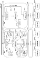
また、各部品配置装置20には、それぞれ固有のアドレスが付与されている。このため、ナビゲーション端末10は、アドレスを指定することによって、自端末に接続される部品配置装置20の他、他端末に接続されている部品配置装置20とも情報の授受を行うことができる。例えば、図3に示すように、ナビゲーション端末10は、制御プログラム1112が通信プログラム1113を介して、自端末に接続されているコントローラ18と通信を行って、対応する部品配置装置20と情報の授受を行う(図3においてピッチの粗い破線X1参照)。また、制御プログラム1112は、必要に応じて、他のナビゲーション端末10に接続されている部品配置装置とも、他ナビゲーション端末10の通信プログラム1113を介して、当該他の端末に接続されているコントローラ18と通信(リモートタスク通信RTC)を行って、対応する部品配置装置20と情報の授受を行う(図3においてピッチの細かい破線X2参照)。
Each
なお、アドレスは、後述する工具装置30にも付されている。従って、ナビゲーション端末10は、工具装置30との間においても、前述した部品配置装置20と同様に、情報の授受を行うことができる。
The address is also assigned to the
工具装置30は、図6に示すように、工具台301に設けられた支持部304に、電動工具として、異なるトルクを持つ3種類のトルクドライバ31から33が配置されている。トルクドライバ31から33には、それぞれビット31b、32bおよび33bが取り付けられている。また、図示していないが、トルクアップ信号が出力され、動作終了検出装置36に入力される(図7参照)。
As shown in FIG. 6, the
一方、各ドライバ31から33には、使用すべき工具であることを作業者に対して視覚的に指示するための指示器群を構成する指示器31a、32aおよび33aが設けられている。また、ドライバが作業者に取り上げられたことを検知するためのセンサ31a、32cおよび33cが設けられている。
On the other hand, each of the
トルクドライバ31から33には、それが使用すべき工具である場合にのみ駆動可能な状態とする機能を付加することができる。例えば、指示器31a、32aおよび33aの指示信号がある場合にのみ、その工具が作動可能にするスイッチ回路を設けることによって実現することができる。一方、同様の機能を、コントローラ側に設けることもできる。すなわち、工具装置30の電源を制御して、各トルクドライバ31から33を駆動する電力の供給を制御することによって、動作すべきトルクドライバのみ作動可能とする構成とすることができる。このようにすることにより、工具を誤って取り上げても、動作しないので、誤った工具を使用することを防ぐことができる。
The
この工具装置30は、4本の脚302と、それに設けられたキャスタ303を有し、移動可能に設けられている。これにより、作業台70の周りの作業しやすい位置に移動できるため、作業能率向上の点で好ましい。また、天板305上に他の工具をのせることができる。さらに、ナビゲーション端末10を載せることもできる。
This
ナビゲーション端末10は、図2に示すように、コンピュータ11と、これに接続される各種周辺装置15から19によりシステムが構成される。コンピュータ11は、CPU12と、主記憶装置13と、インタフェース(1/F)14と、補助記憶装置110とを有する。補助記憶装置110には、OS、一般的なアプリケーションプログラム等の外、本実施形態の機能を実現するための各種プログラム111と、データ115とが格納される。
As shown in FIG. 2, the
インタフェース14は、コンピュータ11と、周辺装置15から19との接続、および、ネットワーク60との接続を、それぞれの物理的な条件とプロトコルとに従って行う。
The
プログラム111には、例えば、図3に示すように、ナビゲーションプログラム1111、制御プログラム1112、通信プログラム1113等が含まれる。コンピュータ11は、必要に応じてデータ115を参照して、これらのプログラムを実行することにより、前述した周辺装置を動作させて、各種機能を実現する。
The
データ115には、例えば、ナビゲーション画面データ1151、作業履歴データ1152、部品/棚対応データ1153、制御パラメータ1154、測定値、検査結果1155等の各種データが含まれる。これらのデータの格納は、全体として一つのデータベースに収容される形式、それぞれが個別のデータベースを構成する形式、個別のファイルとして格納される形式等いずれの形式であってもよい。本実施形態では、ナビゲーション画面の生成必要なデータについては、すべてのナビゲーション端末において、任意の工程についてのデータを参照できるように構成される。
The
ナビゲーション画面データ1151は、工程系列に従って、生産の各作業を順次示すためのナビゲーション画面を表示する、テキストデータ、画像データ、これらを管理するためのデータ等を含む、画面関係データである。このナビゲーション画面データは、例えば、1つの工程を1画面乃至数画面に割り当てて構成される。単純な作業であれば、1工程1画面となり、1工程が複数作業を含み、かつ、作業が複雑な場合、時系列にしたがって複数画面に分けて表示することになる。すなわち、ナビゲーション画面は、複数ページで構成されることとなる。
The
本実施形態では、各画面には、ナビゲーション画面を識別するコードが時系列に付される。このコードは、作業進捗状況を示す情報におけるナビゲーション画面を識別するコードに対応している。本実施形態では、作業ポジションとの対応を示す符号Pmとの対応を、ナビゲーション画面を識別するコードxxとして、例えば、“Pm−xx”のように表記している。この具体例を、図4(A)において、ステータス11522として示す。なお、作業ポジションPと、ナビゲーション画面を識別するコードとの対応関係は、作業現場の状況に応じて柔軟に変更してもよい。
In this embodiment, a code for identifying the navigation screen is attached to each screen in time series. This code corresponds to the code for identifying the navigation screen in the information indicating the work progress status. In the present embodiment, the correspondence with the code Pm indicating the correspondence with the work position is represented as “Pm-xx”, for example, as the code xx for identifying the navigation screen. This specific example is shown as
このナビゲーション画面を表示するためのデータは、製品対応に、各作業ポジションの工程列にしたがってナビゲーション画面を表示する。表示される画面としては、例えば、図9、図10および図11に示す入力画面、図12に示すナビゲーション処理画面等がある。 The data for displaying the navigation screen displays the navigation screen according to the process sequence of each work position corresponding to the product. The displayed screen includes, for example, the input screens shown in FIGS. 9, 10, and 11, the navigation processing screen shown in FIG.
図9は本発明に係る生産ナビゲーションシステムにおいて用いられる作業者ID入力画面の一例を示す。この画面1510の表示は、ナビゲーションプログラム1111に含まれる作業者ID入力処理を行うためのプログラムによって処理される。この作業者ID入力画面1510は、ナビゲーションシステムの立ち上がり後に、または、その作業ポジションに、新たに入力される製品についての作業を受け入れ可能な状態の場合に、表示装置15の表示画面にウインドウ形式により表示される。この作業者ID入力画面1510には、作業者ID欄1511と、作業者ID欄1511に入力された作業者IDの確認のための入力を行うOKボタン1512とが表示される。作業者ID入力欄1511には、入力装置16またはバーコードリーダ17より作業者IDが入力されると、その作業者IDが表示される。
FIG. 9 shows an example of an operator ID input screen used in the production navigation system according to the present invention. The display of this
また、この作業者ID入力画面1510は、バーコードリーダ17からの作業者ID読込による割り込みが発生した場合にも、表示装置15の表示画面にウインドウ表示される。この場合には、作業者ID入力画面1510には、表示時から読み込まれた作業者IDが表示されることになる。この作業者ID入力画面表示のための割り込みは、例えば、作業者が交代する場合等に生じることが想定される。
The worker
図10は本発明に係る生産ナビゲーションシステムにおける初期メニュー画面の一例を示す。この画面1520は、前述した作業者ID入力画面1510において、OKボタン1512が操作されると、ナビゲーションプログラム1111により、表示される。この画面1520には、作業開始を指示するための作業開始ボタン1521と、作業者変更を指示するための作業者変更ボタン1522と、作業終了を指示するための作業終了ボタン1523とが表示される。作業開始ボタン1521が操作されると、図11に示す作業開始メニュー画面1530に移行する。一方、作業者変更1522ボタンが操作されると、これまでの作業者による作業を終了するための処理が行われる。現在の作業者による作業終了に関する処理後、前述した図9に示す作業者ID入力画面1510の表示を行い、新たな作業者の作業者ID入力を待ち、入力があった後、再び、図10の画面1520の表示を行う。他方、作業終了ボタン1523が操作されると、作業を終了するための処理が行われる。この後、図9の画面が表示され、待機状態となる。または、そのまま、立ち上げ状態の画面に移行して、待機状態としてもよい。
FIG. 10 shows an example of an initial menu screen in the production navigation system according to the present invention. This
図11は、本発明に係る生産ナビゲーションシステムおける作業開始メニュー画面の一例を示す。図11に示す画面には、工程票に記載された工程番号を入力する工程番号欄1531と、作業を開始する工程を検索する指示を受け付ける検索ボタン1532と、製品コードを表示する製品コード表示欄1533と、検索の結果、または、入力装置16を介しての手入力の結果として、組立開始工程の表示を行う組立開始工程欄1534とが表示される。また、表示内容に対して、承認の意思表示を入力するためのOKボタン1535と、前に戻る操作指示を受け付ける1536と、入力内容をキャンセルする指示を受け付けるキャンセルボタン1537とがさらに表示される。ここで、工程番号と製品コードとは、作業者に渡される工程票に表記されているバーコード等の識別子をバーコードリーダにより読み取ることにより入力することができる。
FIG. 11 shows an example of a work start menu screen in the production navigation system according to the present invention. The screen shown in FIG. 11 includes a
図12は、本発明に係る生産ナビゲーションシステムおける作業手順を示すナビゲーション画面の一例を示す。図12の例では、画面を大まかに6領域に分けて、それぞれの領域151から156には、予め定めた特定の事項についての表示が割り当てられる。本実施形態では、例えば、次のように表記される
タイトル領域151では、工程列に属するある工程の全部または一部を示すナビゲーション画面を識別するための工程記号の表記151aが行われる。すなわち、その工程が作業ポジションP5での作業として割り当てられることを示すための表記、ここでは“P5−33”の表記と、工程名151b、ここでは、“カバー組付け”の表記がなされる。
FIG. 12 shows an example of a navigation screen showing a work procedure in the production navigation system according to the present invention. In the example of FIG. 12, the screen is roughly divided into six areas, and a display for a predetermined specific item is assigned to each of the
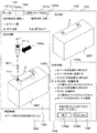
全体図領域152では、当該ナビゲーション画面において作業すべき仕掛品の全体像が表示される。例えば、斜視図により表示される。この図では、この画面での終了状態である組立後の状態を示している。もちろん、この画面での作業開始前の状態と、終了状態とを、一定時間間隔で交互に表示するようにしてもよい。また、それらの中間の状態を含めて、時系列に順次、繰り返し表示する構成としてもよい。
In the
作業手順領域153では、当該ナビゲーション画面において行われるべき作業の手順を示している。図12の例では、aからeまでの各作業の内容を時系列に示すテキスト表示153aがなされている。また、aからeまでの各作業の内容を示すテキスト列の先頭位置に、これから行うべき作業乃至現在行われている作業の内容を示すためのポインタとして、記号または図形として矢印153bが示される。なお、これから行うべき作業乃至現在行われている作業の内容を示す手段として、この他に、または、これと共に、テキストの表示色を変更すること、輝度を変更すること、点滅表示すること、終わった作業内容の表示を消すこと、等の種々の態様が可能である。具体的には、a、b、c、dの順に、部品の取り出し、組立、固定等を行い、eにおいて確認をするという手順が記述されている。この手順については、a、b、c等の符号、説明文全体、符号と説明文の両者について、現在行うべき作業が何であるかを示すために、例えば、色を変えて表示。点滅、蛍光色の背景表示を行う等の強調表示を行う。また、矢印153bにより、作業を行うべき符号の前に表示して、それについて強調表示を行う。この場合、作業の進捗に併せて、この矢印E2の位置を順次移動させていく。
The
なお、作業手順の進行は、作業者が一つ一つの作業を終わる毎に、図2に示す終了スイッチ19による指示を行うことに応じてなされる。すなわち、CPU12は、スイッチ19による割り込み入力を受け付けると、ナビゲーションプログラム1111により、割り込み処理を行い、現在の作業手順の強調表示を次の作業手順を示す表示に移行させる。これにより、作業者の確認を待って、順次、作業手順を進行させていく。なお、スイッチに代えて、また、作業によっては、コントローラからの作業の終了を示す情報を受信することを条件としてもよい。画面上に、確認ボタンを設ける構成としてもよい。
The progress of the work procedure is made in response to an instruction from the
部品・工具表示領域154は、このナビゲーション画面において組立に用いられる部品の表示154aと、使用するジグ・工具についての表示154bとを行う。本実施形態では、部品については使用する順に番号を付して表示する。また、工具についても、部品と対応づけて表示している。
The part /
組立画像を示す領域155には、そのナビゲーション画面において行われるべき組立て作業の手順を示すための画像が表示される。本実施形態では、仕掛品に対して、カバーYと、それらを固定するためのねじとを、装着の順に、斜視図で示している。この例は、静止画1枚で示しているが、作業手順に合わせて複数枚の静止画を同時に、または、順次、表示する構成としてもよい。また、動画により表示してもよい。
In an
確認事項表示領域156は、このナビゲーション画面において行われる作業において、特筆すべき事項、特段の注意が必要な事項についてメモ的に表記している。従って、表記が必要ない場合には、空欄となっている。
The confirmation
さらに、作業手順領域153の中に、完了を指示するための領域157が設けられている。この完了を指示するための領域157には、完了を指示するための完了ボタン157aと、指示を無効とするキャンセルボタン157bが設けられている。
Further, an
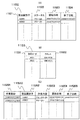
次に、作業履歴データ1152について述べる。作業履歴データ1152は、ナビゲーション画面のページ単位に、実行開始日時等を記録する。具体的には、図4(A)に示すように、各製品を識別する製品識別子11521対応に、当該製品についての作業履歴の内容を示す情報であるステータス11522と、その作業の開始日時11523と、その作業の終了日時11524とが記録される。
Next, the
この作業履歴データ1152は、これまでの作業の履歴がナビゲーション画面単位に記録される。この作業履歴のうち最新の情報が、生産進捗状況を示す情報となる。作業履歴は、当該ナビゲーション端末10Aにおいて行われた作業のみならず、そのラインにおいてなされたすべての作業について、製品対応に記録される。生産進捗状況を示す情報は、例えば、図4(A)に示すように、製品識別子11521に対応づけて、最新の作業状況、本実施形態では、作業を行っているまたは作業が終了した直近のナビゲーション画面を示すステータス11522が記録されている。さらに、そのステータスにおいて示される作業の開始日時11523と、その作業の終了日時11524とが対応づけて記録される。なお、各ナビゲーション端末10の作業履歴データ1152おいて、過去の全作業履歴を記録せず、作業履歴データ1152では、現時点から一定期間(例えば、1週間)前までのデータのみを記録することとしてもよい。この場合、過去のデータは、管理サーバ50の作業実績データ512において蓄積することとしてもよい。
In the
図4(A)の例では、AB001という識別子を持つ製品については、ステータス11522が“P4−28”と記録されている。ここで、28は、そのラインで行うべき工程列に含まれる工程の全部または一部の作業を示すナビゲーション画面を識別するコードである。ナビゲーション画面が、作業流れに沿ってシーケンシャルに示される構成となっている場合には、ナビゲーション画面の順序を示す番号ということもできる。また、P4は、そのナビゲーション画面に示される作業が、P4の作業ポジションに割り当てられ、作業ポジションP4において行うべき作業であることを示している。また、この場合、“P4−28”の作業は、開始日時11523において、2004年07月01日09時27分01秒に作業が開始されたことを示す情報が記録されている。また、終了日時11524において、2004年07月01日09時30分55秒に作業が終了したことを示す情報が記録されている。また、AB002という識別子を持つ製品については、“P3−20”の作業が、開始日時11523において、2004年07月01日09時26分05秒に作業が開始されたことが記録されている。また、終了日時11524は、空欄となっている。終了時刻11524が空欄の場合には、その作業が未だ終わっていないことを示す。なお、ここでは、説明および表示の便宜上、時刻の精度を秒単位としている。秒より下の単位まで記録することができることはもちろんである。
In the example of FIG. 4A, the
この生産進捗状況を示す情報は、他のナビゲーション端末にも送られて、ナビゲーション端末10Aから10Jのそれぞれに記憶される。また、管理サーバ50にもネットワーク60を介して送られ、作業実績データ512に記憶される。ナビゲーション端末10においては、生産進捗状況を示す情報は、前述したように、作業履歴データ1152に記憶される。物理的には、ナビゲーション動作中には、主記憶装置13に、また、保存時には、補助記憶装置110のデータ部115に記憶される。一方、管理サーバ50においても、物理的には、主記憶装置53および補助記憶装置51の作業実績データ512に格納される。
Information indicating this production progress is also sent to other navigation terminals and stored in each of the
作業履歴データとして、このほかに、作業者履歴データ11520等がある。作業者履歴データ11520は、例えば、図4(C)に示すように、作業者ID115201、製品識別子15202、作業内容115203、開始日時115204、および、終了日時115205を含む。ここで、作業内容は、その作業者が作業を行っている作業ポジションと、そのポジションにおいて作業を行った、または、現に行っている工程に対応するナビゲーション画面識別コードを対応付けて記録している。例えば、“AB001”という識別子を持つ製品については、作業内容115203が“P4−22−28”と記録されている。これは、“P4−22”の作業が開始日時115204において示すように、2004年07月01日09時01分01秒に作業が開始され、“P4−28”の作業が終了日時115205において示すように、2004年07月01日09時30分55秒に終了したことを意味する。また、AB002という識別子を持つ製品については、“P4−21”の作業が、開始日時115204において、2004年07月01日09時31分11秒に作業が開始されたことを示す情報が記録され、一方、終了日時115205が空欄となっているため、その作業が未だ終わっていないことを示す。なお、この例において、作業が“P4−21”となっているのは、本来は、作業ポジションP3の作業である“P3−21”の作業を作業ポジションP4において引き取って作業を行ったことを示している。従って、本来の作業ポジションの示す“P3−21”という表記としてもよい。
Other work history data includes
図4(C)の作業者履歴データは、それぞれ必要な項目が作業者ごとに設けられる。この作業者履歴データを蓄積することにより、工程全体の作業能率の監視はもとより、作業者によって、どの作業に時間がかかるかを分析することにも利用することができる。また、作業者の能力、能率を取得するデータとして用いることもできる。 In the worker history data in FIG. 4C, necessary items are provided for each worker. By accumulating the worker history data, it can be used not only to monitor the work efficiency of the entire process but also to analyze which work takes time by the worker. Further, it can be used as data for acquiring the ability and efficiency of the worker.
作業履歴データおよび作業者履歴データは、いずれも、ナビゲーション処理において、作業ステータスが変わるごとに、その開始、終了時刻が記録される。また、作業者履歴データと作業履歴データとは、図示していないマスターデータと関係付けるデータ構造とすることができる。 In the work history data and the worker history data, the start and end times are recorded each time the work status changes in the navigation process. Further, the worker history data and the work history data can have a data structure related to master data (not shown).
部品/棚対応データ1153、部品が、部品棚のどのサブ領域に配置されているかを管理する。具体的には、サブ領域のアドレスにより管理する。アドレスは、例えば、部品配置装置の識別子として棚番号と、段、行、列等を示す情報を含むデータにより構成される。その一例を図4(B)に示す。図4(B)では、部品コード11531と、アドレス11532とが対応づけられて記録されている。このデータは、指示器を作動させるほか、サブ領域へのアクセスがあったことをセンサが検出した場合に、その位置をチェックするための情報としても用いられる。
The part /
制御パラメータ1154は、前述したナビゲーション画面において指示されている各種作業を実行するために必要なパラメータを記憶する。具体的には、ナビゲーション画面内で、作業者がどのように作業を行うべきかについて、具体的な行為内容として特定するデータである。すなわち、“Aという部品を取り上げる”、“ドライバ31によりネジを3回締める”、”Xの高さを測定する”などの、各種作業内容を予め定めた単位で管理する。制御プログラム1112は、この制御パラメータを用いて、ナビゲーション画面での作業の進行に併せて、作動させる指示器を特定し、アクセスがなされたかを確認し、また、工具の指示を行い、工具が使用されたかをチェックする。ナビゲーションプログラム1111は、このチェックに従って、ナビゲーション画面での作業指示の進行を制御する。チェックのトリガーは、本実施形態では、作業者によるスイッチ19の操作により行われる。
The
測定値・検査結果データ1155は、工程中において行われる測定による測定値、検査等の結果を記録する。例えば、工程中に、間隔を一定に保って部品を取り付けるなどの作業が存在する場合、その作業後に、間隔が正しく保たれているかについて測定することが必要になる。その際の測定値が、入力装置16を介して手入力され、または、測定器から自動入力されると、その値を製品対応に記録しておく。また、検査を行う場合には、その検査結果が、入力装置16を介して手入力、または、検査装置から自動入力されると、その検査結果を製品対応に記録しておく。これらの記録は、品質管理のためのデータとして用いられる他、後日、メンテナンス時に参考に供することができる。また、蓄積された測定値、検査結果の履歴は、図示していない設計部門のシステムにも送られ、設計の見直しに利用させることができる。
The measurement value /
ナビゲーションプログラム1111は、第1に、ナビゲーションの開始、終了等の処理を行う。第2に、当該ナビゲーション端末が置かれた位置において、製品の生産を開始する際、当該製品の生産進捗状況を示す情報を取得して、いずれの作業単位から作業を開始すべきかの作業開始単位を決定する手段として機能する。製品の生産進捗状況を示す情報は、図3に示すように、作業履歴データ1152から取得する。第3に、ナビゲーションプログラム1111は、前記開始工程に対応させて、生産すべき製品の組立作業手順と使用する部品とを示すナビゲーション画面を表示装置15に表示させるナビゲーション画面表示手段として機能する。第4に、生産すべき製品について、その進捗状況を示す情報を、それぞれを特定する情報に対応づけて記憶する手段として機能する。
The
制御プログラム1112は、ナビゲーション画面が示す作業手順にしたがって部品の取り出し、工具による組立等を行う際、部品配置装置、工具装置の各動作を制御する。制御プログラム1112は、それが搭載されているナビゲーション端末(例えば10A)のみならず、他のナビゲーション端末(例えば10B)のコントローラ18に対して、当該他のナビゲーション端末(例えば10B)の通信プログラム1113を介して、直接、制御を行うことができる。例えば、取るべき部品が他の作業ポジションの部品配置装置にある場合に、当該部品配置装置において部品を取るべき位置の指示と、アクセスの検出とを制御する。
The
通信プログラム1113は、制御プログラムとコントローラ18との通信を処理する。具体的には、通信プログラム1113は、制御プログラム1112から送られる各種指示操作等の情報を受け付けて、コントローラ18に伝達する。一方、コントローラ18から送られる情報を制御プログラムに伝達する。また、この通信プログラム1113は、図3に示すように、その通信プログラム1113が搭載されているナビゲーション端末10Bの制御プログラム1112から送られる各種指示操作等の情報を受け付けるのみならず、他のナビゲーション端末10Aに搭載された制御プログラム1112により、ネットワーク60を介してリモートタスク通信RTCによって送られる各種指示操作等の情報を受信して、当該ナビゲーション端末10Bに接続されたコントローラ18Bに送ることも行う。このように、他のナビゲーション端末10Bのコントローラ18Bに通信を行うことが可能となっていることから、例えば、ある作業ポジションP2において処理すべき作業を、隣接する他の作業ポジションP1において分担する場合に、当該隣接作業ポジションP1のナビゲーション端末10Aから、本来の作業を行うべき作業ポジションP2のナビゲーション端末10Bのコントローラ18Bに各種指示操作等の情報を送ることができる。例えば、部品配置装置20B2に収容されている部品を取るように、指示する指示器を駆動することができる。また、通信プログラム1113は、部品配置装置20B2からのセンサによる検出信号をコントローラ18Bから受け取って、ネットワーク60を介して、他のナビゲーション端末18Aの制御プログラム1112に送る。なお、リモートタスク通信は、部品配置装置に対する指示に限らず、工具装置30等への指示などにも使用可能である。
The
CPU12は、これらのプログラムを主記憶装置13にロードして実行することによって、各種機能を実現する。例えば、生産すべき製品について、それぞれの進捗状況を示す情報を、製品を識別する情報に対応づけて記憶する手段と、当該ナビゲーション端末が置かれた位置において、製品の生産を開始する際、当該製品についての前記生産進捗状況を示す情報を参照して、いずれのナビゲーション画面から表示するかを決定する手段と、ナビゲーション画面データから前記決定されたナビゲーション画面データを読み出して、ナビゲーション画面を表示するナビゲーション画面表示手段として機能する。また、いずれのナビゲーション画面から表示するかを決定する手段は、製品を識別する情報の入力を受け付けて、当該製品を識別する情報に基づいて、前記生産進捗状況を示す情報を参照して、いずれのナビゲーション画面から表示するかを決定する。
The
次に、管理サーバ50の構成について図2を参照して説明する。管理サーバ50は、コンピュータにより構成される。この管理サーバ50は、補助記憶装置51、インタフェース54と、を有する。補助記憶装置51には、CPU52により実行されるプログラムである作業管理プログラム511と、作業実績データ512と、通信制御プログラム513と、を有する。
Next, the configuration of the
管理サーバ50は、図2に示すように、ネットワーク60を介して、ナビゲーション端末10Aから10Jと接続され、情報の授受を行う。その基本的な機能は、第1に、ネットワーク60に接続される各ナビゲーション端末10Aから10Jに保持される生産ナビゲーションに必要な、前述したナビゲーションプログラム1111他の各種プログラム、および、作業履歴データ11152他の各種データを保持し、必要に応じて、各ナビゲーション端末10Aから10Jに送る機能が上げられる。第2に、各ナビゲーション端末10Aから10Jにおいて行われた生産活動の実績を、それぞれのナビゲーション端末から受け取って記録する。
As shown in FIG. 2, the
次に、本実施形態の動作例について、図8のフローチャートをさらに参照して説明する。この例は、製品の生産の流れに沿って複数台配置されたナビゲーション端末のうちの、いずれかのナビゲーション端末での動作例である。なお、必要に応じて隣接する他のナビゲーション端末の動作についても説明する。 Next, an operation example of this embodiment will be described with further reference to the flowchart of FIG. This example is an operation example in any one of the navigation terminals arranged in a plurality along the product production flow. The operation of other adjacent navigation terminals will be described as necessary.
ナビゲーション端末10Aは、前述したコンピュータ11と、表示装置15からスイッチ19の周辺装置とにより各種機能を実現する。すなわち、生産すべき製品について、それぞれの進捗状況を示す情報を、それぞれを特定する情報に対応づけて記憶する手段と、当該ナビゲーション端末が置かれた位置において、製品の生産を開始する際、当該製品についての生産進捗状況を示す情報を取得して、いずれの作業単位から作業を開始すべきかの作業開始単位を決定する手段と、開始工程に対応させて、製品の生産作業手順および使用する部品を示す画面(ナビゲーション画面)を表示する手段と、を実現する。また、前述したように、ナビゲーション画面表示手段は、当該製品について他のナビゲーション端末において生産されるべき作業手順についてナビゲーション画面を生成するための情報をも記憶している。そして、生産進捗状況に応じて定まる作業開始時点の作業からナビゲーション画面を生成する。
10 A of navigation terminals implement | achieve various functions with the
前提として、ある日の操業開始時点において、ラインの各作業ポジションP1からP5までにそれぞれ作業者が割り当てられる。各作業者には、それぞれ工程票が渡される。また、各作業者は、個人を識別するバーコード付きの識別票を所持している。前述した工程票には、工程番号と、担当する作業ポジションが表記されている。工程票は、例えば、管理サーバ50において出力することができる。また、さらに上位の生産管理システム(図示せず)、それと関連する労務管理システム等において出力する構成としてもよい。
As a premise, an operator is assigned to each work position P1 to P5 on the line at the start of operation on a certain day. Each worker is given a process slip. Each worker also has an identification tag with a barcode for identifying an individual. In the above-mentioned process slip, the process number and the work position in charge are written. The process slip can be output by the
各作業ポジションP1からP5において、ナビゲーション端末10A等について、作業者により、それぞれ立ち上げ操作がされる。立ち上げに伴って、CPU12は、補助記憶装置110から、ナビゲーション処理に必要なプログラム、データ等を読み出して、主記憶装置13にロードする。その後、プログラムを順次実行する。まず、CPU12は、ナビゲーションプログラム1111を実行することにより、一連の作業開始・終了処理を行う(S1からS4)。その後、ナビゲーション処理等を実行する(S5からS9)。
At each work position P1 to P5, the operator performs a start-up operation on the
CPU12は、図9に示す作業者ID入力画面1510を表示装置15の表示画面に表示させ、作業者ID入力処理を行う(S1)。ここで、作業者が、入力装置16またはバーコードリーダ17より作業者IDを入力すると、CPU12は、作業者IDを受け付けて、その作業者IDを作業者ID入力画面1510の作業者ID欄1511に表示させる。作業者による入力装置16からのOKボタン1512に対する操作を受け付けると、
メニュー画面表示に移行する(S2)。
The
A transition is made to the menu screen display (S2).
ステップS2に示すメニュー画面表示処理では、まず、図10に示す初期メニュー画面を表示装置16の表示画面に表示させる。図10に示す画面には、作業開始を指示するための作業開始ボタン1521と、作業者変更を指示するための作業者変更ボタン1522と、作業終了を指示するための作業終了ボタン1523とが表示される。
In the menu screen display process shown in step S <b> 2, first, the initial menu screen shown in FIG. 10 is displayed on the display screen of the
CPU12は、入力装置15からの、いずれかの作業ボタンについての指示操作があると、いずれのボタンの操作かを調べ、それぞれのボタンに対応した処理を行う(S3)。作業開始ボタン1521が操作されると、CPU12は、ステップS4のナビゲーション画面データ読込処理に移行する。また、作業者変更1522ボタンが操作されると、CPU12は、ステップS1に戻り、図9に示す作業者ID入力画面1510を表示させて、前述した処理を行う。一方、作業終了ボタン1523が操作されると、終了処理(S10)を行う。すなわち、これまでに取得したデータを、主記憶装置13から補助記憶装置110に書き込んで保存する。具体的には、また、このデータは、他のナビゲーション端末にも送って、同様に、作業履歴データ1152として記録する。さらに、管理サーバ50にも送って、作業実績データ512に蓄積させる。この後、ナビゲーションプログラム1111は処理を終了する。
When there is an instruction operation on any of the work buttons from the
次に、ステップS4の作業開始画面表示処理では、CPU12は、図11に示す作業開始メニュー画面を表示させる。ここでは、まず、作業者による工程番号および製品識別子の入力受付処理を行う。すなわち、作業者に渡されている工程票からバーコードリーダ17により読み取られた工程番号および製品識別子の入力を受け付ける。受け付けた工程番号は、工程番号欄1531に表示させる。また、製品識別子は、製品識別子(製品コード)欄1533に表示させる。なお、この際、工程票から作業者IDをも読み取ることにすることより、工程票に表記されている作業者と、実際の作業者との一致を確認することができる。ここで、CPU12は、入力装置16を介して行われる検索ボタン1532の操作を受け付ける。これにより、作業履歴データ1152を検索して、当該製品についての最新のステータスを取得して、該当するナビゲーション画面の表示を開始する。例えば、検索された最新のステータスが、“P4−24”であれば、“P4−25”の作業を表示するナビゲーション画面データをナビゲーション画面データ1151から読み出して、表示装置15に表示させる。
Next, in the work start screen display process in step S4, the
ここで、作業ポジションP4におけるナビゲーション端末10D(図示せず)では、例えば、ナビゲーション画面識別コード22−28を分担するものとすると、“製品AB001”は、ナビゲーション画面識別コード28まで作業が終了しているため、この製品の作業は、作業ポジションP5に移行する。
Here, in the
一方、次に作業を行うべき“製品AB002”は、上流側の作業ポジションP3において、作業が遅れており、図4(A)のステータス11522と終了日時11524に示されるように、現在の作業はナビゲーション画面識別コード20についての作業であり、その作業がまだ終了していない。このため、作業ポジションP3において行うべきナビゲーション画面識別コード21が残っていることになる。このような場合、遅れが波及しないように、作業ポジションP4の作業者が上流側の作業ポジションP3の残存作業を、作業ポジションP4での作業の前倒しとして、引き受けることにより、遅れを解消することができる。この場合、図4(C)に示すように、作業者ID“20000102003”の作業者が、割り当てられている作業ポジションP4に配置されているナビゲーション端末10により、作業の再開の入力を行う。その結果、“製品AB002”について、作業履歴データ1152の作業内容115203には“P4−21−”と記録されることになる。すなわち、図4(C)は、作業ポジション4においてナビゲーション画面識別コード21から作業が開始されていることを示している。
On the other hand, the “product AB002” to be worked next is delayed in the work position P3 on the upstream side, and as shown in the
なお、この際、作業ポジションP5の作業者は、“製品AB001”について、P5−29の作業内容から作業を開始することとなる。作業ポジションP5のナビゲーション端末10Eは、この“P5−29”のためのナビゲーション画面の表示を行う。
At this time, the worker at the work position P5 starts work on the “product AB001” from the work content of P5-29. The
図4(C)の例では、上流側の作業の遅れを吸収する例を示した。しかし、本実施形態における作業分担の調整は、このような場合に限られず、柔軟に行うことができる。例えば、上流側の作業が遅れていない場合であっても、下流側の作業が早く終わっている場合には、同様に、下流側が上流側の作業の残りを引き取ることによって、生産に要する時間をより短縮することを可能とする。逆に、下流側の作業が遅れている場合には、上流側が下流側の作業の一部を引き取って、上流側の作業ポジションにおいて作業を行う構成とすることができる。もちろん、この場合にも、下流側の作業が遅れているとはいえない場合にも、上流側が次の製品の作業をすでに終わっている場合には、引き続き、下流側の作業の一部を引き取って行うことにより、下流側の作業負担を軽減して、全体として、生産に要する時間の短縮を可能とする。図4(C)の作業者履歴データは、このような状況を作業者毎に記録する。 In the example of FIG. 4C, an example in which the upstream work delay is absorbed is shown. However, adjustment of work sharing in the present embodiment is not limited to such a case, and can be performed flexibly. For example, even if the upstream work is not delayed, if the downstream work is finished early, similarly, the downstream side takes up the remainder of the upstream work, thereby reducing the time required for production. It is possible to shorten it further. Conversely, when the downstream work is delayed, the upstream side can take a part of the downstream work and perform the work at the upstream work position. Of course, in this case as well, even if it cannot be said that the downstream work is delayed, if the upstream side has already finished the work of the next product, it will continue to pick up part of the downstream work. As a result, the work load on the downstream side is reduced, and the time required for production can be shortened as a whole. The worker history data in FIG. 4C records such a situation for each worker.
また、このような作業の引取等が行われる場合には、ナビゲーション画面も、当然のことながら、他の作業ポジションにおける作業であっても、表示可能であることが必要となる。本実施形態では、前述したように、ナビゲーション画面データとして、工程列全体のものを各ナビゲーション端末に用意している。また、作業履歴データを他のナビゲーション端末において参照できるため、いずれの作業ポジションであっても、他の作業ポジションの作業を行うことが可能である。しかし、すべての部品を、すべての作業ポジションについて共通に行うのは現実的ではない。そこで、隣接する作業ポジションにおいて使用する可能性の高い部品を、それぞれの部品配置装置20に用意しておく構成として、対処することが考えられる。本実施形態ではそのようにしている。なお、この場合、隣接する作業ポジションを含めて部品が用意されていない作業ポジションのナビゲーション端末において、製品識別子の入力が行われると、そこでは、部品を容易に取得できる作業ポジションを表示して、作業すべき作業ポジションを変更するようメッセージを表示装置15に表示する構成としてもよい。
Further, when such work is taken over, the navigation screen needs to be able to be displayed even if it is a work at another work position. In the present embodiment, as described above, the navigation screen data for the entire process sequence is prepared for each navigation terminal. In addition, since the work history data can be referred to in other navigation terminals, it is possible to work at other work positions at any work position. However, it is not realistic to perform all parts in common for all work positions. In view of this, it is conceivable to deal with a configuration in which parts that are likely to be used in adjacent work positions are prepared in the respective component placement apparatuses 20. This is the case in this embodiment. In this case, when the product identifier is input in the navigation terminal of the work position where the part including the adjacent work position is not prepared, the work position where the part can be easily obtained is displayed, A message may be displayed on the
次に、CPU12は、前述した種々の状況に応じて定まる、当該作業ポジションにおける作業開始画面を、表示装置15に表示させる。この種の画面としては、例えば、図12に示すような画面が用いられる。
Next, the
図12に示す生産ナビゲーション画面は、その画面内で1乃至複数の作業について、使用する部品、工具、作業手順、作業後の全体図を一覧できるように、また、それぞれを区分けしてみることができるように、画面を区画して示している。図12に示す例は、仕掛品にカバーYを組み付ける工程での作業の手順を示す。作業者は、この画面に表示される作業について、自らが割り当てられた作業であるのかを確認した上で、作業手順に従って、作業を進める。この画面に基づく各処理、広義のナビゲーション処理を、ナビゲーションプログラム1111と制御プログラム1112とが実行する(S5)。
The production navigation screen shown in FIG. 12 can be used to list the parts to be used, tools, work procedures, and the overall view after work for one or more work in the screen. The screen is divided and shown so that it can be done. The example shown in FIG. 12 shows the procedure of the operation in the process of assembling the cover Y to the work in progress. The worker confirms whether the work displayed on this screen is an assigned work, and then proceeds with the work according to the work procedure. The
CPU12は、ナビゲーション画面の作業手順に沿って、必要な制御を行う。すなわち、制御プログラム1112により、部品/棚対応データ1153を参照して、部品の取得位置の指示に必要な部品の位置を示すデータを参照して、部品棚における指示を制御する。先ず、作業手順において取るべき部品を置いた部品棚の指示と、それが置かれている位置の指示とを行うアクセス位置指示を、コントローラ18に送る。コントローラ18は、シーケンサ181により、予め定めた手順に従って、指示された指示器の駆動制御を行う。例えば、カバーYが、部品棚25のサブ領域25−17に置かれている場合には、その位置を示す指示器26−17を点灯させる(図5(B)の指示モード)と共に、それが配置されている部品棚25を指示する26−0を点灯させる。これにより、作業者に、どの部品棚のどの位置に、取るべき部品が存在するかを知らせることができる。このときは、図12の表示画面の矢印153bが、同図に示す位置ではなく、作業手順aの位置に存在して、例えば、矢印153bの表示を点滅させることにより、作業者に対して、行うべき作業があることについて注意を促す。また、取付部品名を示す領域において、該当する部品を強調表示することを併せて行ってもよい。
The
ここで、作業者が、指示器26−17が示すサブ領域に手を入れて、部品を取り出すと、センサ群27の当該サブ領域を警戒するセンサによって、そのアクセスが検出される。アクセス位置情報出力装置22により、この検出信号から、その検出したセンサの位置を特定する情報、すなわち、アクセス位置情報が生成され、当該情報がコントローラに18に送られる。コントローラ18のシーケンサ181は、このアクセス位置情報を受け取ると、点灯を指示した指示器の位置情報と比較する。一致している場合には、例えば、指示器26−17を、一定時間、例えば、10秒ほど、緑色発光する(図5(B)確認モード)。その後、指示器26−17を消灯する(図5(B)の待機モード)。このようにすることにより、作業者が確かに部品を取り出したということを確認することができる。また、シーケンサ181は、指示された部品の取り出しアクセスがあったことを示す情報を、指示をしたナビゲーション端末の制御プログラムに送る。ここでは、当該コントローラ18が接続されているナビゲーション端末の制御プログラムに送る。
Here, when the worker puts his hand into the sub area indicated by the indicator 26-17 and takes out the part, the access is detected by a sensor which alerts the sub area of the
ここで、指示器の位置情報と、アクセス位置情報とが不一致である場合、作業者が誤ったサブ領域にアクセスしているため、その事態を報知するための警告を行う。例えば、図示していないブザー等を鳴動させて、注意を喚起することが考えられる。 Here, if the position information of the indicator does not match the access position information, a warning is given to notify the situation because the worker is accessing the wrong sub-region. For example, it is conceivable to call attention by sounding a buzzer (not shown).
CPU12は、作業者により操作されたスイッチ19による、作業が終わったことを確認する信号の入力を受け付ける。この入力に伴って、制御プログラム1112が、コントローラ18からの部品取り出しアクセスがあったことを示す情報を受け取って、作業手順を次に進める。具体的には、作業手順aに示される作業から、作業手順bに示される作業を行うべきことを、作業者に示す。例えば、図12に示すように、矢印153bをその作業手順bに対応づけて表示させると共に、点滅表示を行う。
CPU12 receives the input of the signal which confirms that the work was completed by
なお、作業が終わったことを確認する信号と、コントローラ18からのアクセスがあったことを示す情報の入力との論理積をとって、次のステップに進むことの判断を、CPU12が行う構成としてもよい。このようにすることによって、部品を取り損ねた場合に、次のステップの表示に進むことを抑止することが可能となる。
Note that the
これを受けて、作業者は、カバーYを本体に装着する。そして、スイッチ19を押す。これにより、作業が終わったことを確認する信号がコンピュータ10に入力されることになる。
In response to this, the operator attaches the cover Y to the main body. Then, the
CPU12は、ナビゲーション画面に表示される作業手順の実行を管理する際、画面に表示される作業手順に対応する具体的な作業行為を特定する制御パラメータ1154を参照する。
When managing the execution of the work procedure displayed on the navigation screen, the
カバーYが本体に装着されたことについて、スイッチ19の操作に基づく、作業者による確認が入力されると、CPU12は、行うべき作業を作業手順cに進める。具体的には、制御プログラム1112が、ナビゲーションプログラム1111に、行うべき作業の表示を次の作業手順(ここでは作業手順c)に進めるよう指示する。ここで、前述したように、コントローラ18に対して、部品、この場合は、ネジを収容しているサブ領域を指示するように指示する。また、図12の画面において、ネジの表示について強調表示する。そして、センサによる検出に基づく、部品取り出しアクセスがあったことを示す情報を受け取ると、それ自体で、または、スイッチ19の押し込みと共に、制御プログラム1112は、作業手順をdに進めるようナビゲーションプログラム1111に指示する。
When confirmation by the operator based on the operation of the
CPU12は、作業dでは、ナビゲーションプログラム1111により、ネジ2本をトルクドライバにより締める作業を、画面において強調表示の対象とする。また、制御プログラム1112により、制御パラメータ1154を参照して、工具装置30に対する使用する工具を示すための指示器の作動指示と、ネジ締め制御とを行わせる。例えば、図6に示す工具31を使用するものとすると、制御プログラム1112は、使用すべき工具の情報と、締めトルクの情報とを、ナビゲーション画面データ1151から取得する。その情報に基づいて、コントローラ18に、工具装置30に対する工具の指示と、動作の監視とを行わせる指示を送る。
In the operation d, the
コントローラ81は、この指示を受信すると、シーケンサ181において、予め定めた制御シーケンスに従って、工具装置30における使用工具、例えば、ドライバ31の指示器31aを作動させる。例えば、発光させる。そして、作業者が、当該工具を取り上げて、ネジ溝にトルクドライバの先端を当てて、回転させる。このとき、動作終了検出装置36のセンサ、例えば、トルクアップセンサにより、一定以上のトルクで一定回転数回転することを検出すると、検出信号をシーケンサ181に送る。シーケンサ181は、検出信号を受けて、トルクドライバの停止を工具装置30に指示する。ここまでの動作を、ネジを締めるべき本数分行う。その後、ネジ締めが終了したことを、ナビゲーション端末10のCPU12に通知する。
When the controller 81 receives this instruction, the
CPU12においてネジ締め終了の通知を受け付けると、制御プログラム1112は、ナビゲーションプログラム1111に対して、次の作業として行うべき作業が作業手順eであることを示すように指示する。作業手順eでは、カバーYの組み付けが終了した時点で、カバーYに緩みがないかを確認する作業について強調表示する。すなわち、前述したように、図12では作業手順bの位置にある矢印153bを、作業手順eの位置に表示して、点滅させつつ、作業手順eを指示させる。
When the
ここで、作業者は、指示された確認作業を終わると、スイッチ19を操作する。このスイッチ19の操作により、CPU12は、作業手順eに示す作業が終了したと判断する。また、作業者は、このナビゲーション画面においては、次に行うべき作業手順が表示されていないので、完了ボタン157aを入力装置15からの指示により操作する。
Here, the operator operates the
CPU12は、この作業終了指示があると(S6)、このナビゲーション画面で行うべき作業がすべて行われているかのチェック、すなわち完了チェックを行う(S7)。完了チェックは、例えば、作業手順aからeについて、確認がすべてなされているかを、主記憶装置13に記憶されている作業終了確認データを検索して、作業手順と対比することにより行う。そして、すべての作業が行われている場合には、完了と判断し(S8)、これまでの作業データを作業履歴データ1152に格納する(S9)。その後、ステップS1に戻り、作業IDの入力を待つ。一方、完了していない場合には、ステップS5のナビゲーション処理に戻り、完了していない作業について再度作業を行うよう指示する。この後、再び完了チェックを行う。そして、すべて作業が完了したところで、前述したように、ステップS1に戻る。
When there is this work end instruction (S6), the
なお、作業の終了は、その作業ポジションに割り当てられたすべての作業手順を終わらせることを要しない。ナビゲーション画面の単位で終了させることが可能である。終了の典型的な場合は、終業時における終了である。このほかに、休憩時間、作業者の交代等が挙げられる。終了の後、同じ作業ポジションで作業を再開することができる。再開時は、当該仕掛り中の製品の製品識別子をナビゲーション端末に入力することによって、そのナビゲーション端末において作業を再開することができる。また、隣接した他の作業ポジションにおおいて作業を再開することもできる。 Note that the completion of the work does not require that all work procedures assigned to the work position are finished. It is possible to end in units of the navigation screen. A typical case of termination is termination at the end of work. In addition to this, there are break times, worker changes, and the like. After completion, work can be resumed at the same work position. At the time of resumption, by inputting the product identifier of the product in process to the navigation terminal, the work can be resumed at the navigation terminal. Also, the work can be resumed at another work position adjacent thereto.
隣接する作業ポジションにおける作業手順の一部を、上流側または下流側の作業ポジションにおいて、引き受ける場合の制御について説明する。図3に、このような場合の情報の流れを示しているので、図3を参照して説明する。 A description will be given of the control when a part of the work procedure at the adjacent work position is accepted at the work position on the upstream side or the downstream side. FIG. 3 shows the flow of information in such a case, which will be described with reference to FIG.
図3に示すように、制御プログラム1112は、自ナビゲーション端末10Aに接続されているコントローラ18のみならず、他端末10Bに接続されているコントローラ18に対しても、指示を、ネットワーク60を介して送ることができる。もちろん、この逆の場合も可能であることはいうまでもない。
As shown in FIG. 3, the
前述したように、ラインに並ぶすべてのナビゲーション端末において、任意のナビゲーション画面を表示することができる。そのため。ナビゲーション画面の表示という点では、いずれの作業ポジションの作業であっても対応可能である。隣接する作業ポジションP2において行うべき作業手順の一部について、作業ポジションP1に位置するナビゲーション端末10Aにおいて作業手順を示しつつ、作業者に作業を行わせる場合にも、もちろん対応することができる。一方、使用する部品については、部品棚の収容量の制限、在庫量の低減の要請等から、すべての作業ポジションにおいて、すべての部品が用意されているわけではない。そのため、ある作業ポジションで隣接作業ポジションにおいて行われるべき作業手順の一部を引き受けると、その作業のための部品が当該作業ポジションに属する部品配置装置に用意されていないことがあり得る。このような場合、隣接する本来作業を行うべき作業ポジションに配置されている部品配置装置20から部品を取り出すこととなる。このような場合の指示の仕方について説明する。
As described above, an arbitrary navigation screen can be displayed on all navigation terminals arranged in a line. for that reason. In terms of the display of the navigation screen, work at any work position can be handled. Of course, some of the work procedures to be performed at the adjacent work position P2 can be dealt with when the worker performs the work while showing the work procedures at the
ナビゲーション端末10Aの制御プログラム1112は、ナビゲーション画面に表示されている部品がいずれの棚に存在するかを、部品/棚対応データ1153を参照して調べる。ここで、部品/棚対応データ1153には、ラインすべての部品/棚データを予め格納しておく。従って、検索することで、必要な部品の所在を示す情報を得ることができる。この場合、隣接する作業ポジションP2のナビゲーション端末10Bに接続される部品配置装置20B2に存在するものとする。
The
そこで、制御プログラム1112は、部品/棚対応データ1153を参照して、部品配置装置20B2に該当する部品が存在することを索出すると、その情報に基づいて、その部品の位置を示す指示器を作動させる指示を、リモートタスク通信RTCにより、ネットワーク60を介して、ナビゲーション端末10Bの通信プログラム1113に送る。通信プログラム1113は、コントローラ18Bに、作業手順において取るべき部品が置かれている部品棚の指示と、当該部品棚におけるその部品が置かれている位置とを指示するアクセス位置指示を送る。コントローラ18Bは、シーケンサ181(図7参照)により、予め定めた手順に従って、指示された指示器の駆動制御を行う。例えば、部品Xが、部品棚25のサブ領域25−18に置かれている場合には、その位置を示す指示器26−18を点灯させると共に、それが配置されている部品棚25を指示する26−0を点灯させる。これにより、作業者に、どの部品棚のどの位置に、取るべき部品が存在するかを知らせることができる。
Therefore, when the
前述したように、隣接する作業ポジション間で、作業手順の引取がある場合、ある作業ポジションに置かれている部品棚において、その作業ポジションの作業者の他に、隣接する作業ポジションの作業者が部品を取ることが起こる。このような場合に、部品棚の指示器26−0および指示器26−1から26−24について、発光色を、その作業ポジションにおける使用部品を指示する場合と区別して、異なるものとすることができれば、より好ましい。図5(A)の指示器26の場合であれば、各指示器26−1から26−24、および、指示器26−0について、それぞれ三色が発光可能な素子とする。また、シーケンサ181では、作業ポジジョンからのアクセス位置指示に対応して予め定めた三色のうちいずれの色を発光させるかを示す発光色指示信号を各指示器に送る。この発光色指示信号の指示に応じて、各指示器26−0および指示器26−1から26−24に、作業ポジション対応の発光色により発光するための、駆動制御回路を設けておく。このような構成とした上で、例えば、自作業ポジションPiに赤、上流側隣接作業ポジションPi-1に青、下流側隣接作業ポジションPi+1に緑、というように色分けして発光色を割り当てる。
As described above, when a work procedure is picked up between adjacent work positions, in addition to the worker at the work position, the worker at the adjacent work position can be found on the parts shelf placed at the work position. Taking parts takes place. In such a case, the light emission colors of the parts shelf indicator 26-0 and the indicators 26-1 to 26-24 may be different from those in the case of instructing the parts used in the work position. It is more preferable if possible. In the case of the
このようにすることにより、例えば、作業ポジションPiを担当する作業者は、赤が割り当てられているので、自作業ポジションと、隣接する二つの作業ポジションとにおいて、いずれかの部品棚の指示器26−0が赤色発光している場合には、その赤色発光している指示器26−0が属する部品棚において、指示器26−1から26−24のうち、赤色発光している指示器のサブ領域から部品を取り込むことになる。一方、自作業ポジションにおいて、三色の表示がなされることとなる。そのため、作業者は、自作業ポジションにおいても、割り当てられた色による指示がある場合のみ、部品取り出しを行うこととする。このようにすることによって、作業者が取るべき部品について迷ったり、誤ったりすることを防ぐことができる。
By doing so, for example, since the worker in charge of the work position Pi is assigned red, the
ここで、作業者が、指示器26−18が示すサブ領域に手を入れて、部品を取り出すと、センサ群27の当該サブ領域を警戒するセンサによって、そのアクセスが検出される。アクセス位置情報出力装置22により、この検出信号から、その検出したセンサの位置を特定する情報、すなわち、アクセス位置情報を生成して、コントローラに18Bに送られる。コントローラ18Bのシーケンサ181は、このアクセス位置情報を受け取ると、点灯を指示した指示器の位置情報と比較する。一致している場合には、指示された部品の取り出しアクセスがあったことを示す情報を、指示をしたナビゲーション端末10Aの制御プログラム1112に送る。
<第2の実施形態>
次に、本発明の第2の実施形態について、図13から図18を参照して説明する。なお、第2の実施形態は、ナビゲーション画面の構成が相違する点を除いては、基本的には、前述した第1の実施形態と同様のシステムにより実現することができる。従って、以下では、相違点を中心として説明する。
Here, when the worker puts his hand into the sub area indicated by the indicator 26-18 and takes out the part, the access is detected by a sensor which alerts the sub area of the
<Second Embodiment>
Next, a second embodiment of the present invention will be described with reference to FIGS. The second embodiment can be basically realized by the same system as the first embodiment described above except that the configuration of the navigation screen is different. Therefore, hereinafter, the description will focus on the differences.
ナビゲーション画面データ1151は、前述したように、工程系列に従って、生産の各作業を順次示すためのナビゲーション画面を表示する、テキストデータ、画像データ、これらを管理するためのデータ等を含む、画面関係データである。このナビゲーション画面データは、単純な作業であれば、1工程1画面となり、1工程が複数作業を含み、かつ、作業が複雑な場合、時系列にしたがって複数画面に分けて表示することになる。本実施形態では、1つの工程を数画面に割り当てて構成される部分を示す。すなわち、ナビゲーション画面は、複数ページで構成されることとなる。本実施形態においても、各画面には、ナビゲーション画面を識別するコードが時系列に付される。
As described above, the
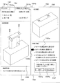
図13から図18には、本発明の第2の実施形態に係る生産ナビゲーションシステムおける作業手順を示すナビゲーション画面の一例を示す。これらの図に示すナビゲーション画面は、より具体的には、ある生産ラインにおける工程系列に沿って生産ナビゲーションを行う場合のある工程を、4つの画面により、順次、作業手順を示す構成となっている。これらの画面に示す工程は実際の作業を模式的に示す都合上簡略化して表記してある。実際には、実際の製品が示されるため、説明図、手順等がより具体的なものとなる。図13から図18の例においても、それぞれにおいて画面を大まかに6領域に分けている。それぞれの領域151から156には、予め定めた特定の事項についての表示が割り当てられる。これらの領域151から156における表示は、ナビゲーション画面データ1111に格納されている。また、ナビゲーション画面の切り換えに必要な情報等は、作業履歴データ1152に格納されている。そして、画面の切り換えは、制御プログラム1112による指示を受けて行う。ここで、本実施形態におけるナビゲーション画面による作業手順のナビゲーション動作について、前述した第1の実施形態と同じ、カバーの組み付け作業を例として、図13から図18を参照して説明する。
FIGS. 13 to 18 show an example of a navigation screen showing a work procedure in the production navigation system according to the second embodiment of the present invention. More specifically, the navigation screens shown in these drawings are configured to sequentially show work procedures on four screens for processes in which production navigation may be performed along a process sequence in a certain production line. . The steps shown in these screens are simplified for convenience in order to schematically show actual work. Actually, since an actual product is shown, an explanatory diagram, a procedure, and the like become more specific. Also in the examples of FIGS. 13 to 18, the screen is roughly divided into 6 regions in each. Each of the
タイトル領域151では、図13から図18のそれぞれのタイトル領域151おいて示すように、工程列に属するある工程の全部または一部を示すナビゲーション画面を識別するための表記151aが表示される。すなわち、その工程が作業ポジションP5での作業として割り当てられることを示すための表記として、図13の画面から図16の画面までは、“P5−33”から“P5−36”と表記されている。また、図17から図18の画面までは、“P5−38”から“P5−39”と表記されている。P5の表記と、工程名151bの表記、ここでは、“カバー組付け”の表記がなされる。なお、“P5−37”に対応する画面は、本実施形態としては用意される。しかし、“P5−35”と左右の違いがあるのみであるので、本明細書においては図示を省略している。
In the
全体図領域152では、“P5−33”から“P5−39”までの作業を完了することによって得られる製品(仕掛品WIP)の形態を示している。例えば、斜視図により表示される。図13から図18の各図では、これらの画面によるすべての作業の終了状態である組立後の状態を示している。すなわち、この例では、“P5−39”の組立画像を示す領域155での表記と同様に示される。もちろん、異なる態様で示されてもよい。例えば、それぞれの画面での完成状態を順次示す構成としてもよい。また、各画面における作業開始前の状態と、当該画面での終了状態とを、一定時間間隔で交互に表示するようにしてもよい。さらに、図13から図18に至るまでの、中間の状態を含めて、時系列に順次、繰り返し表示する構成としてもよい。これを、より多くの画像を用いて、動画表示としてもよい。
The
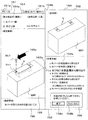
作業手順領域153では、図13から図18に示すように、各画面において、作業手順aからgに、対応する各作業手順の内容を示すテキスト表示153aが示されている。従って、作業手順を読むことで、行うべき作業を実行することができる。このため、作業内容を記憶していなくても実行することができるので、作業に不慣れな作業者であっても作業を行うことが可能となる。また、音声によりガイドしてもよい。
In the
これらの作業手順aからgは、それぞれの作業を行うべきタイミングに応じて強調表示される。例えば、図13では作業手順aについて、矢印153bにより注目すべき位置が示されると共に、“カバーYを部品棚から取り出す”というテキスト自体が太字表示等の各種態様により強調表示される。
These work procedures a to g are highlighted according to the timing at which each work should be performed. For example, in FIG. 13, for the work procedure a, the position to be noted is indicated by an
強調表示としては、特定色による表示、輝度の変更、点滅、字体変更、サイズ変更、蛍光色の背景表示等、およびそれらの組合せなど、種々可能である。この作業手順の強調表示は、図13から図18に示すように、作業の進行に伴って、作業点順aからg間で、順次変位していく。従って、作業者は、強調表示されている作業が、現時点において行うべき作業であることを容易に知ることができる。また、前後の作業内容についても参照できるので、作業の流れを把握しつつ、今行うべき作業を知ることができる。もちろん、既に終わった作業内容を示すテキストの表示を削除することも可能である。 Various highlighting methods are possible, such as display with a specific color, change in luminance, blinking, font change, size change, fluorescent color background display, and combinations thereof. As shown in FIGS. 13 to 18, the highlighting of the work procedure is sequentially displaced between the work point orders a to g as the work progresses. Therefore, the worker can easily know that the highlighted work is the work to be performed at the present time. In addition, since the work contents before and after can be referred to, the work to be performed can be known while grasping the flow of the work. Of course, it is also possible to delete the display of the text indicating the work content that has already been completed.
なお、作業手順の進行は、作業者が一つ一つの作業を終わる毎に、図2に示す終了スイッチ19による指示を行うことに応じてなされる。すなわち、CPU12は、スイッチ19による割り込み入力を受け付けると、ナビゲーションプログラム1111により、割り込み処理を行い、画面を次の画面に切り替える。これに伴って、現在の作業手順の強調表示を次の作業手順を示す表示に移行される。これにより、作業者の確認を待って、順次、作業手順を進行させていく。なお、スイッチに代えて、また、作業によっては、コントローラからの作業の終了を示す情報を受信することを条件としてもよい。画面上に、確認ボタンを設ける構成としてもよい。
The progress of the work procedure is made in response to an instruction from the
部品・工具表示領域154は、このナビゲーション画面において組立に用いられる部品の表示154aと、使用するジグ・工具についての表示154bとを行う。本実施形態では、部品については使用する順に番号を付して表示する。また、工具についても、部品と対応づけて表示している。例えば、図13では、部品棚から取るべき部品として、また、図14では、本体に装着すべき部品として、それぞれ“カバーY”について強調表示がなされている。図15から図17では、部品棚から取るべき部品として、また、図14では、本体に装着すべき部品として、それぞれ“ネジ2本”について強調表示がなされている。この例では、“ネジ2本”として表示されているが、より具体的にネジ名、番号等を併せて表示してもよい。また、ネジ1本ずつ順次表記してもよい。また、図16および図17においては、使用工具として、“トルクドライバ”について強調表示がなされる。なお、強調表示としては、前述した作業手順の場合と同様に、輝度変更、色変更、文字サイズ変更、蛍光表示等、種々の態様が可能である。また、必要なもののみ表示することとして、強調表示とすることとしてもよい。前述の作業手順における表示についても同様であるが、要は、作業者に、行うべき作業内容が明確に告知できる表記であればよい。
The part /
組立画像を示す領域155には、そのナビゲーション画面において行われるべき作業手順を示すための画像が表示される。本実施形態では、図13から図18まで、作業手順の流れに従って、斜視図が示される。
In an
図13では、カバーYと仕掛品WIPとが、斜視図により示されている。これにより、どのような部品が必要かを、視覚的に知ることができる。図14では、さらに、カバーYとそれを装着すべき仕掛品WIPの部分とを、一点鎖線により結んで、カバーYを、どのような向きで、仕掛品WIPのどの部分に装着すべきかを図示している。図13および図14では、それぞれカバーYの表示態様が強調表示されている。すなわち、これらの図では、斜線を付して示している。これは、特許図面の表記上の都合である。実際の表示画面では、パターンの貼り付け、テクスチャの貼り付け、色変更、輝度変更等の、各種表示態様により強調表示が行われる。また、一点鎖線についても、点滅表示、点滅等により、協調表示することができる。さらに、後述する図15等のように、矢印などの図形を用いて、または、それと併せて用いることによって、強調表示することもできる。 In FIG. 13, the cover Y and the work-in-process WIP are shown in a perspective view. This makes it possible to visually know what parts are necessary. In FIG. 14, the cover Y and the part of the work-in-process WIP to which the cover Y is to be attached are connected by a one-dot chain line, and in what direction the cover Y should be attached to the part of the work-in-process WIP. Show. In FIGS. 13 and 14, the display mode of the cover Y is highlighted. In other words, these drawings are shown with diagonal lines. This is for the convenience of notation of patent drawings. On the actual display screen, highlighting is performed by various display modes such as pattern pasting, texture pasting, color change, and brightness change. In addition, the alternate long and short dash line can also be cooperatively displayed by blinking display, blinking, or the like. Further, as shown in FIG. 15 and the like to be described later, highlighting can be performed by using a graphic such as an arrow or in combination with it.
図15では、作業手順cの“ネジSC1を部品棚から取り出す”という作業に対応して、カバーYが装着された仕掛品WIPの斜視図と、使用するネジSC1とが示されている。そして、ネジSC1が取り付けられるべきネジ穴SH1(図14参照)に通じる貫通孔TH1との対応関係を一点鎖線により示している。これにより、ネジSC1が取り付けられるネジ穴が、作業者に示されることとなる。ここでは、ネジSC1を強調表示するため、矢印155aがネジSC1に近接して表示されている。この矢印155aは、ネジSC1を協調するための表示である。この矢印に代えて、または、それと共に、異なる強調表示を行うこともできる。例えば、ネジ自体の表示色の変更、輝度の変更、点滅等の強調表示を行うことができる。
FIG. 15 shows a perspective view of the work-in-process WIP with the cover Y mounted thereon and the screw SC1 to be used, corresponding to the work “c. The correspondence relationship with the through hole TH1 leading to the screw hole SH1 (see FIG. 14) to which the screw SC1 is to be attached is indicated by a one-dot chain line. Thereby, the screw hole to which the screw SC1 is attached is shown to the operator. Here, in order to highlight the screw SC1, an
図16では、作業手順dの“ネジSC1を締める”という作業に対応して、カバーYが装着された仕掛品WIPの斜視図と、使用するネジSC1と、ネジSC1を締めるための工具としてトルクドライバ31’が示されている。そして、トルクドライバ31’とネジSC1が取り付けられるべき貫通孔TH1との対応関係を一点鎖線により示している。また、ネジ穴SH1に通じる、カバーYに設けられた貫通孔TH1について、塗りつぶしにより強調表示を行っている。これにより、ネジSC1が取り付けられるネジ穴SH1に通じる貫通孔TH1が、作業者に示されることとなる。なお、貫通孔TH1の協調表示は、塗りつぶしに限られない。色表示、輝度変更、点滅等の種々の態様が可能である。また、矢印等により示すことによって協調してもよい。
In FIG. 16, in response to the work of “tightening screw SC <b> 1” in work procedure d, a perspective view of work-in-process WIP with cover Y attached, screw SC <b> 1 to be used, and torque as a tool for fastening screw SC <b> 1. A driver 31 'is shown. The correspondence relationship between the
図16では、工具として、トルクドライバ画像31’が表示されている。このトルクドライバ画像31’は、図6に示すトルクドライバ31に対応している。そして、図9において、使用すべきトルクドライバを指示する指示器31aの指示表示に対応して、図16内のトルクドライバ画像31’についても、同じような指示器画像31a’が表示される。従って、作業者は、このトルクドライバ画像31’と、その指示器画像31a’とを見ることにより、使用すべき工具を正しく把握することができる。なお、本実施形態では、トルクドライバ画像31’について、矢印155aによる強調表示を行っている。もちろん、トルクドライバ画像31’自体について、表示色の変更、輝度の変更、点滅等の表示態様を変更することにより強調表示することとしてもよい。なお、ネジ締め時の条件として、ネジ締めトルクが併せて表示される。この表示は、あくまでも参考であり、本実施形態では、制御プログラム1112によりトルクの指示が行われ、シーケンサ18において指定されたトルクとなるよう制御される。
In FIG. 16, a torque driver image 31 'is displayed as a tool. This torque driver image 31 'corresponds to the
図17においても、図16に示す場合と同様の表示が行われる。ただし、図17では、ネジSC2を締めることについての表示である。なお、前述したように、ネジSC2に対は、図15に相当する図の表示は省いてある。 Also in FIG. 17, the same display as that shown in FIG. 16 is performed. However, in FIG. 17, it is a display about tightening screw SC2. As described above, the illustration corresponding to FIG. 15 is omitted for the screw SC2.
図18では、ねじSC1およびSC2を締め終わった状態で、カバーYが緩みなく取り付けられているかを調べるため、“カバーYにゆるみがないかを確認”との作業手順gに対応する画像が表示される。この図は、実質的には、全体図領域152に示される完成図と同じである。ただし、確認すべき部分を示すための強調表示として、矢印155aが表示されている。この矢印155aの表示に代えて、または、この表示と共に、他の強調表示、例えば、色変更、輝度変更、点滅等の各種強調表示を行うことができる。
In FIG. 18, in order to check whether or not the cover Y is attached without loosening after the screws SC1 and SC2 are tightened, an image corresponding to the operation procedure g “Check whether the cover Y is loosened” is displayed. Is done. This view is substantially the same as the completed view shown in the
本実施形態の場合、図13から図17に示すように、作業手順領域153の中に、終了を指示するための領域158が設けられている。この終了を指示するための領域158には、終了を指示するための終了ボタン158aと、指示を無効とするキャンセルボタン158bが設けられている。ところで、本実施形態では、図13から図17に示すように、ナビゲーション画面“P5−33”から“P5−38”までの各作業が、一単位ずつになっているため、その終了時に、それぞれの画面での作業の終了を指示するための領域における終了ボタン158aを用いることができる。また、前述した第1の実施形態と同様にスイッチ19を操作することにより、作業の完了をコンピュータ11に通知する構成とすることもできる。もちろん、終了ボタン158aとスイッチ19とを併用することもできる。なお、終了を指示するための領域158を表示することを省略する構成としてもよい。
In the case of this embodiment, as shown in FIGS. 13 to 17, an
また、図18に示すこの工程の最後の作業を示す画面では、作業手順領域153の中に、完了を指示するための領域157が設けられている。この完了を指示するための領域157には、完了を指示するための完了ボタン157aと、指示を無効とするキャンセルボタン157bが設けられている。作業が完了すると、作業の完了を指示するための領域における完了ボタン157aを用いることができる。また、前述した第1の実施形態と同様にスイッチ19を操作することにより、作業の完了をコンピュータ11に通知する構成とすることもできる。もちろん、完了ボタン157aとスイッチ19とを併用することもできる。
Further, in the screen showing the last work of this process shown in FIG. 18, an
確認事項表示領域156は、このナビゲーション画面において行われる作業において、特筆すべき事項、特段の注意が必要な事項についてメモ的に表記している。従って、表記が必要ない場合には、空欄となっている。
The confirmation
次に、本実施形態の動作について説明する。本実施形態における処理の流れは、基本的には、前述した第1の実施形態同様であるが、1工程が複数画面により表示される点に相違がある。図19に示すフローチャートに説明する。 Next, the operation of this embodiment will be described. The flow of processing in this embodiment is basically the same as in the first embodiment described above, but there is a difference in that one process is displayed on a plurality of screens. This will be described with reference to the flowchart shown in FIG.
第1の実施形態では、図12に示す同じ画面のなかで、指示態様の変化に応じて作業を行い、スイッチ19の操作により作業終了を入力することが行われた。本実施形態では、作業単位に画面が変化するため、画面毎に一つの作業を行って、スイッチ19を操作して、または、終了ボタン158aを操作して、その画面での作業の終了をコンピュータ11に知らせる。CPU12は、作業終了が当該工程での最後のナビゲーション画面における終了かを判定し(S16)、最後の画面での終了ではない場合、次のナビゲーション画面データを読み込んで、表示装置15に表示させる。例えば、図13の処理が終了したと判断すると、図14に示すナビゲーション画面の表示を行う。同様にして、図14から図18までの画面を表示して、ナビゲーション処理を行う(S5)。一方、最後の画面である場合には、前述した作業手順領域に記述されているすべての作業手順aからgまでが処理されているかを調べ(S17)、完了していない場合には、ステップA5に戻り、該当する作業を含む画面を表示装置15に表示させる(S18)。完了している場合には、CPU12は、主記憶装置15に記録されている作業履歴を、作業履歴データ1152として保存処理する。作業履歴データの保存処理は、前述した第1の実施形態と同様に行う。
In the first embodiment, in the same screen shown in FIG. 12, the work is performed according to the change of the instruction mode, and the work end is input by operating the
そして、すべての処理が終了すると、ステップS1に戻り、次の工程の処理に移る。また、この工程が当該ラインの最終工程であれば、仕掛品、すなわち、製品を当該ラインから出力させる。一方、最後の工程ではない場合には、さらに、次の工程における作業のナビゲーションに移る。 When all the processes are completed, the process returns to step S1 and proceeds to the next process. If this process is the final process of the line, the work-in-process, that is, the product is output from the line. On the other hand, if it is not the last step, the operation moves to the navigation for the next step.
以上の第2の実施形態においても、隣接する作業ポジションにおいて、作業の一部を取り込むことができる。本実施形態では、画面が1作業単位となっているため、いずれの画面でも、当該画面での作業が終了している限り、以後の作業を下流側の作業ポジションに移すことができる。一方、上流側においても、そのまま1乃至複数画面分の下流側の作業ポジションに割り当てられている作業を、上流が作業ポジションにおいて、そのまま続行することが可能である。
<変形例>
以上に述べた各実施形態は、本発明の典型的な例であって、本発明はこれに限定されず、種々の実施形態が実現可能である。例えば、以下のような例が挙げられる。
Also in the second embodiment described above, it is possible to capture a part of work at adjacent work positions. In this embodiment, since the screen is a unit of work, as long as the work on the screen is completed on any screen, the subsequent work can be moved to the downstream work position. On the other hand, on the upstream side, it is possible to continue the work assigned to the downstream work position for one to a plurality of screens as it is at the upstream work position.
<Modification>
Each embodiment described above is a typical example of the present invention, and the present invention is not limited to this, and various embodiments can be realized. For example, the following examples are given.
第1に、作業者IDの変形例が挙られる。以上に述べた例では、作業者IDを表記する媒体としてバーコードを用いる場合について説明した。しかし、本発明はこれに限定されない。例えば、接触式または非接触式のICカードを用いてもよい。さらに、個人認証データを有する携帯電話、ICカード内蔵携帯電話等を用いることもできる。この場合には、バーコードリーダに代えて、ICカードのリーダを用いる。 First, there is a modification of the worker ID. In the example described above, the case where a barcode is used as a medium for indicating the worker ID has been described. However, the present invention is not limited to this. For example, a contact type or non-contact type IC card may be used. Furthermore, a mobile phone having personal authentication data, a mobile phone with a built-in IC card, or the like can be used. In this case, an IC card reader is used instead of the barcode reader.
第2に、部品を取り出す作業者の手を区別することが挙げられる。前述した実施形態では、進入した作業者の手をどの作業者の手であるかを区別していない。しかし、作業者の手を区別する構成とすることもできる。例えば、作業者に作業者IDを記録したRFID(Radio Frequency Identification)等のICタグを取り付けた指輪を指に装着させると共に、サブ領域にICタグのリーダ・ライタを配置することで、作業者IDを取得すると共に、部品サブ領域への収容と、サブ領域からの取り出しとを、管理する構成とすることができる。このようにすることによって、部品棚にアクセスしたものがいずれの作業者であるかを区別することができる。その結果、例えば、部品の取り出しが取るべき作業者によって正しく行われたかを検知することが可能となる。なお、指輪に代えて、RFIDを装着した腕輪としてもよい。 Secondly, it is possible to distinguish the hand of the operator who takes out the parts. In the embodiment described above, it is not distinguished which operator's hand is the operator's hand that has entered. However, it is also possible to adopt a configuration that distinguishes the hands of the worker. For example, by attaching a finger with a ring attached with an IC tag such as RFID (Radio Frequency Identification) that records the worker ID to the finger, and placing a reader / writer of the IC tag in the sub area, the worker ID In addition, it is possible to manage the housing in the component sub area and the removal from the sub area. In this way, it is possible to distinguish which worker has accessed the parts shelf. As a result, for example, it is possible to detect whether the part has been correctly taken out by the operator. Instead of the ring, a bracelet fitted with RFID may be used.
第3に、部品の識別をRFIDにより行う例が挙げられる。すなわち、全部または一部の部品について、RFIDを付けて、部品自体の管理を行う構成としてもよい。このようにすることによって、部品の個別の動きを検出することが可能となる。その結果、部品の管理を、部品毎に、個別的に行うことが可能となる。 Third, there is an example in which parts are identified by RFID. That is, it is good also as a structure which attaches RFID about all or one part components, and manages components itself. By doing so, it becomes possible to detect individual movements of the parts. As a result, component management can be performed individually for each component.
第4に、製品の識別をRFIDにより行う例が挙げられる。すなわち、製品識別子についても、バーコードに代えて、RFID等のICタグを用いることができる。この場合、書き込み可能なICタグを用いることにより、終了したステータスをICタグに書き込むことができる。これにより、仕掛かり品自体でも、ステータスを記録することが可能となる。その結果、作業進捗状況情報と照合することにより、現品確認と共に、作業開始工程の確認を併せて行うことができる。 Fourth, there is an example in which product identification is performed by RFID. That is, for the product identifier, an IC tag such as RFID can be used instead of the barcode. In this case, the completed status can be written to the IC tag by using a writable IC tag. This makes it possible to record the status of the work-in-process itself. As a result, by collating with the work progress status information, the work start process can be confirmed together with the actual product confirmation.
第5に、工程票についても、RFIDを用いたICタグ化することができる。例えば、ICタグ等に、工程番号、製品コードを記憶させ、ICタグから工程番号、製品コードを、無線、または、有線で読み出すことによって、これらの情報を取り込む構成とすることができる。このようにすることによって、リーダ・ライタに工程票をかざすだけで、工程番号、製品識別子等を、ナビゲーション端末10に入力することが可能となる。
Fifth, the process slip can also be made into an IC tag using RFID. For example, the process number and the product code are stored in an IC tag or the like, and the process number and the product code are read from the IC tag wirelessly or by wire so that these pieces of information can be captured. In this way, the process number, product identifier, etc. can be input to the
第6に、前述した実施形態では、作業履歴データ1152に各ナビゲーション端末における履歴を収容している。しかし、これに限られない。作業履歴データを、最後に作業を行ったナビゲーション端末に当該製品の作業履歴を記録し、他のナビゲーション端末において作業の再開処理が行われた場合、当該他のナビゲーション端末からの要求に応じて、作業履歴データを送る構成とすることができる。
Sixth, in the above-described embodiment, the history of each navigation terminal is stored in the
第7に、また、管理サーバ50の作業実績データに格納し、各ナビゲーション端末において必要に応じてデータを取り込む構成としてもよい。具体的な対応としては、次のようなものが挙げられる。例えば、管理サーバ50は、各ナビゲーション端末10Aから10Jから送られる、製品の生産進捗状況を示す情報を記憶する手段と、記憶する手段に記憶される生産進捗状況を示す情報を、いずれかのナビゲーション端末からの要求に応じて、製品毎にネットワークを介して出力する手段と、を備える構成とすることができる。この場合、ナビゲーション画面表示手段は、当該製品について他のナビゲーション端末において生産されるべき組立作業手順についてナビゲーション画面を生成するための情報をも記憶し、生産すべき製品についての生産進捗状況を示す情報を前記管理サーバに要求し、送られた情報を取り込み、取り込んだ生産進捗状況に応じて定まる作業開始時点の作業からナビゲーション画面を生成し、当該ナビゲーション端末での生産を終了した製品についての生産進捗状況を示す情報を前記管理サーバに送ること、を特徴とする生産ナビゲーションシステムとすることができる。この場合においても、各ナビゲーション端末において行われる処理は基本的には前述した実施形態の場合と同様に行われる。
Seventh, the
10(10A,10B,…)…ナビゲーション端末、11…コンピュータ、110…補助記憶装置、111…プログラム、115…データ、12…CPU、13…主記憶装置、14…インタフェース(I/F)、15…表示装置、16…入力装置、17…バーコードリーダ、18…コントローラ、19…作業終了スイッチ、20(20A,20B,…)…部品配置装置、21…アクセス位置指示装置、22…アクセス位置情報出力装置、25…棚、26(26−1から26−24)…指示器群、センサ群27、30…工具装置、31…電動工具、34…工具指示器、35…動作終了検知装置、150…ナビゲーション画面、151…工程表示領域、152…部品表示領域、153…手順表示領域、154…部品表示領域、155…組立画像表示領域、156…確認事項表示領域、157…作業完了入力領域、50…管理サーバ、60…ネットワーク、70…移動作業台、80…補給端末。
10 (10A, 10B,...) ... navigation terminal, 11 ... computer, 110 ... auxiliary storage device, 111 ... program, 115 ... data, 12 ... CPU, 13 ... main storage device, 14 ... interface (I / F), 15 ... Display device, 16 ... Input device, 17 ... Bar code reader, 18 ... Controller, 19 ... Work end switch, 20 (20A, 20B, ...) ... Part placement device, 21 ... Access position indication device, 22 ... Access position information Output device, 25: shelf, 26 (26-1 to 26-24) ... indicator group,
Claims (11)
前記複数のナビゲーション端末は、それぞれ前記製品の生産の流れに沿って配置され、
前記各ナビゲーション端末は、
生産すべき製品の生産作業手順、および、使用する部品を、画面に表示するためのナビゲーション画面データを記憶する手段と、
前記記憶する手段から、前記ナビゲーション画面データを読み出して、生産すべき製品の生産作業手順を、使用する部品と共に、表示装置に表示させるナビゲーション画面表示手段と、を備え、
前記ナビゲーション画面表示手段は、前記作業手順と、使用する部品とについて、画像とテキストにより表示すること
を特徴とするナビゲーションシステム。 A production navigation system comprising a plurality of navigation terminals connected via a network and supporting production in each navigation terminal,
Each of the plurality of navigation terminals is arranged along a production flow of the product,
Each of the navigation terminals is
Means for storing the production work procedure of the product to be produced and the navigation screen data for displaying the parts to be used on the screen;
A navigation screen display means for reading the navigation screen data from the storage means and displaying a production work procedure of a product to be produced together with parts to be used on a display device;
The navigation system is characterized in that the navigation screen display means displays the work procedure and the parts to be used with images and text.
前記複数のナビゲーション端末は、それぞれ前記製品の生産の流れに沿って配置され、
前記各ナビゲーション端末は、
生産すべき製品の生産作業手順、使用する部品、および、使用する工具を、画面に表示するためのナビゲーション画面データを記憶する手段と、
前記記憶する手段から、前記ナビゲーション画面データを読み出して、生産すべき製品の生産作業手順を、使用する部品および使用する工具と共に、表示装置に表示させるナビゲーション画面表示手段と、を備え、
前記ナビゲーション画面表示手段は、前記作業手順、使用する部品、および、使用する工具について、画像とテキストにより表示すること
を特徴とするナビゲーションシステム。 A production navigation system comprising a plurality of navigation terminals connected via a network and supporting production in each navigation terminal,
Each of the plurality of navigation terminals is arranged along a production flow of the product,
Each of the navigation terminals is
Means for storing navigation screen data for displaying on the screen the production work procedure of the product to be produced, the parts to be used, and the tools to be used;
A navigation screen display means for reading the navigation screen data from the storage means and displaying a production work procedure of a product to be produced on a display device together with parts to be used and tools to be used;
The navigation screen display means displays the work procedure, the parts to be used, and the tools to be used with images and text.
前記ナビゲーション画面表示手段は、複数の作業を一画面に表示した画面を表示し、かつ、前記作業手順を示すテキスト表示について、行うべき作業について表示態様を変更して表示することを特徴とするナビゲーションシステム。 The navigation system according to any one of claims 1 and 2,
The navigation screen display means displays a screen on which a plurality of tasks are displayed on one screen, and displays a text display indicating the work procedure by changing a display mode for the work to be performed. system.
前記ナビゲーション画面表示手段は、一作業を一画面に表示した画面を表示し、かつ、前記作業手順を示す画像およびテキストの表示について、行うべき作業について表示態様を変更して表示することを特徴とするナビゲーションシステム。
を特徴とするナビゲーションシステム。 The navigation system according to any one of claims 1 and 2,
The navigation screen display means displays a screen in which one work is displayed on one screen, and displays an image and text indicating the work procedure by changing a display mode for the work to be performed. Navigation system.
A navigation system characterized by
生産すべき製品の生産作業手順、使用する部品を画面に表示するためのナビゲーション画面データを記憶する手段と、
前記記憶する手段から、前記ナビゲーション画面データを読み出して、生産すべき製品の作業手順を、使用する部品と共に、表示装置に表示させるナビゲーション画面表示手段と、を備え、
前記ナビゲーション画面表示手段は、前記作業手順と、使用する部品とについて、画像とテキストにより表示すること
を特徴とするナビゲーション端末。 A navigation terminal for supporting production,
Means for storing the production work procedure of the product to be produced and navigation screen data for displaying the parts to be used on the screen;
The navigation screen display means for reading the navigation screen data from the storing means and displaying the work procedure of the product to be produced together with the parts to be used on a display device,
The navigation screen display means displays the work procedure and the parts to be used as images and text.
生産すべき製品の生産作業手順、使用する部品、および、使用する工具を画面に表示するためのナビゲーション画面データを記憶する手段と、
前記記憶する手段から、前記ナビゲーション画面データを読み出して、生産すべき製品の生産作業手順を、使用する部品および使用する工具と共に、表示装置に表示させるナビゲーション画面表示手段と、を備え、
前記ナビゲーション画面表示手段は、前記作業手順、使用する部品、および、使用する工具について、画像とテキストにより表示すること
を特徴とするナビゲーション端末装置。 A navigation terminal for supporting production,
Means for storing the production work procedure of the product to be produced, the parts to be used, and the navigation screen data for displaying the tools to be used on the screen;
A navigation screen display means for reading the navigation screen data from the storage means and displaying a production work procedure of a product to be produced on a display device together with parts to be used and tools to be used;
The navigation terminal device characterized in that the navigation screen display means displays the work procedure, the parts to be used, and the tools to be used with images and text.
前記ナビゲーション画面表示手段は、複数の作業を一画面に表示した画面を表示し、かつ、前記作業手順を示すテキスト表示について、行うべき作業について表示態様を変更して表示することを特徴とするナビゲーション端末。 In the navigation terminal according to any one of claims 5 and 6,
The navigation screen display means displays a screen on which a plurality of tasks are displayed on one screen, and displays a text display indicating the work procedure by changing a display mode for the work to be performed. Terminal.
前記ナビゲーション画面表示手段は、一作業を一画面に表示した画面を表示し、かつ、前記作業手順を示す画像およびテキストの表示について、行うべき作業について表示態様を変更して表示することを特徴とするナビゲーション端末。 In the navigation terminal according to any one of claims 5 and 6,
The navigation screen display means displays a screen in which one work is displayed on one screen, and displays an image and text indicating the work procedure by changing a display mode for the work to be performed. Navigation terminal.
作業の終了を入力するための手段を有し、前記手段からの作業の終了の入力があると、次の作業を示す表示の態様を変更して表示することを特徴とするナビゲーション端末。 In the navigation terminal according to any one of claims 5, 6, 7 and 8,
A navigation terminal comprising means for inputting the end of work, and when the end of work is input from the means, the display mode indicating the next work is changed and displayed.
生産すべき製品の生産作業手順、使用する部品を画面に表示するためのナビゲーション画面データを記憶装置に記憶させておき、
前記記憶装置から、前記ナビゲーション画面データを読み出して、生産すべき製品の作業手順を、使用する部品と共に、表示装置に表示させ、
前記ナビゲーション画面表示は、前記作業手順と、使用する部品とについて、画像とテキストにより表示すること
を特徴とする生産を支援する方法。 A method of supporting production,
The production work procedure of the product to be produced and the navigation screen data for displaying the parts to be used on the screen are stored in the storage device,
The navigation screen data is read from the storage device, and the work procedure of the product to be produced is displayed on the display device together with the parts to be used.
In the navigation screen display, the work procedure and the parts to be used are displayed as images and text.
生産すべき製品の生産作業手順、使用する部品、および、使用する工具を画面に表示するためのナビゲーション画面データを記憶装置に記憶させておき、
前記記憶装置から、前記ナビゲーション画面データを読み出して、生産すべき製品の生産作業手順を、使用する部品および使用する工具と共に、表示装置に表示させ、
前記ナビゲーション画面表示は、前記作業手順、使用する部品、および、使用する工具について、画像とテキストにより表示すること
を特徴とする生産を支援する方法。 A method of supporting production,
The navigation screen data for displaying the production work procedure of the product to be produced, the parts to be used, and the tools to be used on the screen are stored in the storage device,
The navigation screen data is read from the storage device, and the production work procedure of the product to be produced is displayed on the display device together with the parts to be used and the tools to be used.
The navigation screen display displays the work procedure, the parts to be used, and the tools to be used with images and texts.
Priority Applications (1)
| Application Number | Priority Date | Filing Date | Title |
|---|---|---|---|
| JP2004286564A JP2006099558A (en) | 2004-09-30 | 2004-09-30 | Production navigation system and navigation terminal |
Applications Claiming Priority (1)
| Application Number | Priority Date | Filing Date | Title |
|---|---|---|---|
| JP2004286564A JP2006099558A (en) | 2004-09-30 | 2004-09-30 | Production navigation system and navigation terminal |
Publications (1)
| Publication Number | Publication Date |
|---|---|
| JP2006099558A true JP2006099558A (en) | 2006-04-13 |
Family
ID=36239284
Family Applications (1)
| Application Number | Title | Priority Date | Filing Date |
|---|---|---|---|
| JP2004286564A Pending JP2006099558A (en) | 2004-09-30 | 2004-09-30 | Production navigation system and navigation terminal |
Country Status (1)
| Country | Link |
|---|---|
| JP (1) | JP2006099558A (en) |
Cited By (8)
| Publication number | Priority date | Publication date | Assignee | Title |
|---|---|---|---|---|
| JP2007328668A (en) * | 2006-06-09 | 2007-12-20 | Hitachi Information & Communication Engineering Ltd | Work management system |
| JP2009093583A (en) * | 2007-10-12 | 2009-04-30 | Shinmei Ind Co Ltd | Operation content instruction system and operation content instruction method |
| JP2010211623A (en) * | 2009-03-11 | 2010-09-24 | Brother Ind Ltd | Work support system |
| WO2015189940A1 (en) * | 2014-06-11 | 2015-12-17 | 三菱電機株式会社 | Screen drawing software |
| JP2016144846A (en) * | 2015-02-09 | 2016-08-12 | 株式会社日立製作所 | Assembly navigation system and assembly navigation method |
| KR20190049787A (en) | 2016-10-13 | 2019-05-09 | 미쓰비시덴키 가부시키가이샤 | Production support system, indicator, production support method, production support program and recording medium |
| CN112400197A (en) * | 2018-11-20 | 2021-02-23 | 株式会社日立系统 | Training teaching material display system and training teaching material display method |
| CN114503040A (en) * | 2019-11-22 | 2022-05-13 | 欧姆龙株式会社 | Work instruction system and work instruction method |
-
2004
- 2004-09-30 JP JP2004286564A patent/JP2006099558A/en active Pending
Cited By (11)
| Publication number | Priority date | Publication date | Assignee | Title |
|---|---|---|---|---|
| JP2007328668A (en) * | 2006-06-09 | 2007-12-20 | Hitachi Information & Communication Engineering Ltd | Work management system |
| JP2009093583A (en) * | 2007-10-12 | 2009-04-30 | Shinmei Ind Co Ltd | Operation content instruction system and operation content instruction method |
| JP2010211623A (en) * | 2009-03-11 | 2010-09-24 | Brother Ind Ltd | Work support system |
| WO2015189940A1 (en) * | 2014-06-11 | 2015-12-17 | 三菱電機株式会社 | Screen drawing software |
| KR101772355B1 (en) | 2014-06-11 | 2017-08-28 | 미쓰비시덴키 가부시키가이샤 | Computer readable medium for recording a screen drawing software |
| CN106463095B (en) * | 2014-06-11 | 2018-04-17 | 三菱电机株式会社 | Drawing practice |
| JP2016144846A (en) * | 2015-02-09 | 2016-08-12 | 株式会社日立製作所 | Assembly navigation system and assembly navigation method |
| CN105867318A (en) * | 2015-02-09 | 2016-08-17 | 株式会社日立制作所 | Assemble guide system and method |
| KR20190049787A (en) | 2016-10-13 | 2019-05-09 | 미쓰비시덴키 가부시키가이샤 | Production support system, indicator, production support method, production support program and recording medium |
| CN112400197A (en) * | 2018-11-20 | 2021-02-23 | 株式会社日立系统 | Training teaching material display system and training teaching material display method |
| CN114503040A (en) * | 2019-11-22 | 2022-05-13 | 欧姆龙株式会社 | Work instruction system and work instruction method |
Similar Documents
| Publication | Publication Date | Title |
|---|---|---|
| CN100442176C (en) | Control system setting device | |
| JP6412055B2 (en) | Injection molding machine management system | |
| JP4715710B2 (en) | RFID system, RFID cable system, RFID cable laying method | |
| JP2011130658A (en) | Cable system, rfid built-in cable, and rfid built-in cable and data base | |
| EP2755096A1 (en) | Work management system, work management terminal, program and work management method | |
| JP2006172387A (en) | System for production navigation and apparatus for part arrangement | |
| US20070156278A1 (en) | Monitoring device for machining apparatus | |
| JP2011203775A (en) | Field equipment maintenance device | |
| US10889928B2 (en) | Production management system, sewing machine, and production management device | |
| JP2006099558A (en) | Production navigation system and navigation terminal | |
| JP2007164446A (en) | Manufacturing process management system | |
| CN111095195A (en) | Controller, control method, and control program | |
| JP6677701B2 (en) | Tool storage | |
| JP6761004B2 (en) | Tool management system, tool management device and tool management method | |
| JP6832741B2 (en) | Work support system, work support method and program | |
| JP2011258118A (en) | Daily work report preparation supporting device and daily work report preparation supporting method | |
| JP2006072599A (en) | Production navigation system | |
| JP5634633B1 (en) | Joint hardware supply control system, control program therefor, and recording medium | |
| JP2003150224A (en) | System and method for automatically grasping man-hour | |
| JP2005056272A (en) | System for grasping working hour and system for creating working instruction | |
| JP2001014017A (en) | Program controller for nc machine tool | |
| JP2005259078A (en) | Support apparatus and management system | |
| US10591906B2 (en) | Manufacturing environment management system | |
| JP2021068255A (en) | Equipment management system and equipment management method | |
| US20230083887A1 (en) | Image creation support device and image creation support method |