JP2006087672A - Clothes dryer - Google Patents
Clothes dryer Download PDFInfo
- Publication number
- JP2006087672A JP2006087672A JP2004276839A JP2004276839A JP2006087672A JP 2006087672 A JP2006087672 A JP 2006087672A JP 2004276839 A JP2004276839 A JP 2004276839A JP 2004276839 A JP2004276839 A JP 2004276839A JP 2006087672 A JP2006087672 A JP 2006087672A
- Authority
- JP
- Japan
- Prior art keywords
- drain pump
- clothes dryer
- pump
- reverse direction
- drying
- Prior art date
- Legal status (The legal status is an assumption and is not a legal conclusion. Google has not performed a legal analysis and makes no representation as to the accuracy of the status listed.)
- Pending
Links
Images


Abstract
Description
本発明は、業務用に、或いは一般家庭で洗濯作業などに使用される衣類乾燥機に関するものである。 The present invention relates to a clothes dryer used for business use or for washing work in general households.
従来、この種の衣類乾燥機は、蒸発器で除湿された空気を凝縮器を通し、乾燥空気として回転ドラムに循環させて乾燥を行うようにしていた(例えば、特許文献1参照)。 Conventionally, in this type of clothes dryer, air dehumidified by an evaporator is passed through a condenser and circulated as dry air to a rotary drum for drying (see, for example, Patent Document 1).
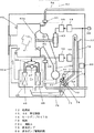
図10は、上記特許文献1に記載された従来の衣類乾燥機の概略断面図を示すもので、本体1内に、回転ドラム2、モータ3、送風機22、循環ダクト18、蒸発器23、凝縮器24、圧縮機25、絞り装置26、インバータ回路32を設け、インバータ回路32によって圧縮機25を駆動しつつ、回転ドラム2内に入れられた洗濯物などの被乾燥物20に送風機22により矢印で示したような風を当て、蒸発器23で除湿された空気を、凝縮器24へ導き、乾燥空気として再び回転ドラム2内に循環させ、乾燥空気の一部は排気口28から外部に排出する構成のものであった。
FIG. 10 is a schematic cross-sectional view of the conventional clothes dryer described in the above-mentioned
21は、本体1の底面に開口し、蒸発器23で発生した凝縮水を排出するための排出口である。
しかしながら、上記従来の衣類乾燥機では、蒸発器23で発生した凝縮水を排出する排出口21が本体1の底面に形成されていたので、下方向に滴下し、床面を濡らすことになり、設置できる場所が限定されるという課題を有していた。
However, in the conventional clothes dryer, since the
これを防ぐ為に、衣類乾燥機の下方に、容器等を置き、結露水が受けられるようにするなどの方策は考えられるが、その場合には衣類乾燥機の設置高さが高くなり、また凝縮水で容器が一杯になる前に捨てる必要があることから、非常に手間がかかるという課題もあった。 In order to prevent this, a measure such as placing a container under the clothes dryer to receive condensed water can be considered, but in that case the installation height of the clothes dryer is increased, There is also a problem that it is very time-consuming because the container needs to be discarded before the container is filled with condensed water.
また、排出口21に排水用のホースを接続する方法も考えられるが、蒸発器23、凝縮器24、圧縮機25、絞り装置26からなるヒートポンプサイクルを回転ドラム2の下方に設ける場合には、ホースは衣類乾燥機の最下部となり、設置場所によっては排水が困難となるという課題を有していた。
A method of connecting a drain hose to the
本発明は、上記従来の課題を解決するもので、結露水の処理の為に設置場所が制約される事のない、使用勝手の良い衣類乾燥機を提供することを目的としている。 SUMMARY OF THE INVENTION The present invention solves the above-described conventional problems, and an object of the present invention is to provide an easy-to-use clothes dryer that does not restrict the installation location for the treatment of condensed water.
前記従来の課題を解決するために、本発明の衣類乾燥機は、衣類を収納する乾燥庫と、前記乾燥庫と風路で接続され熱交換器を有し前記衣類を乾燥させるヒートポンプサイクルと、前記衣類乾燥により発生した水分を含む空気を前記熱交換器を通す際に発生する結露水を排水する排水ポンプと、前記排水ポンプを正方向および逆方向に駆動する排水ポンプ駆動回路を備えたもので、排水ポンプを正方向に駆動することで熱交換器で発生する結露水を自然滴下などにより機器外に放出(垂れ流し)するのではなく、例えば排水用の管など、しかるべき経路へと結露水を送ることが可能となり、また、排水ポンプを逆方向に駆動することにより、衣類から発生する糸くず(リント)などの異物により排水ポンプの詰まり、ロック状態(停止状態)となったり、流量が極端に少なくなり性能低下などを起こすことを極力防ぐことができることから、高い信頼性を有しつつ、床面が水で濡れると困るような場所への機器の設置も可能となり、置き場所を選ばない衣類乾燥機を実現させることができる。 In order to solve the above-described conventional problems, a clothes dryer of the present invention includes a dryer for storing clothes, a heat pump cycle connected to the dryer by an air passage and having a heat exchanger to dry the clothes, A drainage pump for draining condensed water generated when air containing moisture generated by drying the clothes is passed through the heat exchanger, and a drainage pump drive circuit for driving the drainage pump in the forward and reverse directions In this way, the condensed water generated in the heat exchanger is not discharged (dripping) out of the equipment by natural dripping, etc., by driving the drain pump in the forward direction, but it is condensed on the appropriate route such as a drain pipe. It is possible to send water, and by driving the drain pump in the reverse direction, the drain pump is clogged by foreign matter such as lint generated from clothing, locked (stopped) It is possible to install the equipment in a place where it is difficult to get wet when the floor surface gets wet with high reliability. The clothes dryer can be realized regardless of the place.
本発明の衣類乾燥機は、結露水の処理の為に設置場所が制約される事の無いものである。 The clothes dryer of the present invention is not restricted in installation location for the treatment of condensed water.
第1の発明は、衣類を収納する乾燥庫と、前記乾燥庫と風路で接続され熱交換器を有し前記衣類を乾燥させるヒートポンプサイクルと、前記衣類乾燥により発生した水分を含む空気を前記熱交換器を通す際に発生する結露水を排水する排水ポンプと、前記排水ポンプを正方向および逆方向に駆動する排水ポンプ駆動回路を備えたもので、排水ポンプを正方向に駆動することで熱交換器で発生する結露水を自然滴下などにより機器外に放出(垂れ流し)するのではなく、例えば排水用の管など、しかるべき経路へと結露水を送ることが可能となり、また、排水ポンプを逆方向に駆動することにより、衣類から発生する糸くず(リント)などの異物により排水ポンプの詰まり、ロック状態(停止状態)となったり、流量が極端に少なくなり性能低下などを起こすことを極力防ぐことができることから、高い信頼性を有しつつ、床面が水で濡れると困るような場所への機器の設置も可能となり、置き場所を選ばない衣類乾燥機を実現させることができる。 The first invention includes a drying cabinet for storing clothing, a heat pump cycle connected to the drying cabinet by an air passage and having a heat exchanger for drying the clothing, and air containing moisture generated by drying the clothing. It is equipped with a drainage pump that drains the condensed water generated when passing through the heat exchanger, and a drainage pump drive circuit that drives the drainage pump in the forward and reverse directions, by driving the drainage pump in the forward direction. Condensed water generated in the heat exchanger is not discharged (dripping) out of the equipment by natural dripping, etc., but it is possible to send the condensed water to an appropriate route such as a drain pipe, and a drain pump By driving in the reverse direction, foreign matter such as lint generated from clothing will clog the drainage pump, become locked (stopped), and the flow rate will be extremely low, resulting in poor performance. As much as possible, it is possible to install equipment in places where the floor surface gets wet with water while maintaining high reliability, realizing a clothes dryer that can be placed anywhere. Can be made.
第2の発明は、特に、第1の発明の排水ポンプ駆動回路は、排水ポンプに流れる電流を検知する過電流検知手段を有し、前記排水ポンプに流れる電流が所定値を越えたら前記排水ポンプの駆動を停止し、その後逆方向に駆動するようにしたもので、排水ポンプの回転部分や水の入り口に、例えば衣類から出た糸くず(リント)などの異物が詰まり、過電流検知手段が電流を検知して異常を検知した時、一旦正方向への運転を停止した後、逆方向に駆動させることにより、上記の異物を取り除くことができ、再び排水ポンプを機能させることができる。 According to a second aspect of the invention, in particular, the drainage pump drive circuit according to the first aspect of the invention has overcurrent detection means for detecting a current flowing through the drainage pump, and the drainage pump when the current flowing through the drainage pump exceeds a predetermined value. The drive is stopped and then driven in the opposite direction. The rotating part of the drainage pump and the water inlet are clogged with foreign matter such as lint from clothes, and overcurrent detection means When an abnormality is detected by detecting a current, the foreign matter can be removed and the drainage pump can be made to function again by driving in the reverse direction after stopping the operation in the positive direction.
第3の発明は、特に、第1又は第2の発明の結露水の水位を検知する水位センサを有し、排水ポンプ駆動回路は前記水位センサから高水位信号を受けて、排水ポンプを逆方向に駆動するもので、排水ポンプの回転部分や水の入り口に、例えば衣類から出た糸くず(リント)などの異物が詰まった場合、水位が異常に高くなるので、逆方向に駆動させることによって、上記の異物を取り除くことができ、再び排水ポンプを機能させることができる。 In particular, the third invention has a water level sensor for detecting the level of condensed water of the first or second invention, and the drain pump driving circuit receives a high water level signal from the water level sensor and reverses the drain pump. If the foreign substance such as lint from clothes is clogged in the rotating part of the drainage pump or the water inlet, the water level becomes abnormally high. The foreign matter can be removed, and the drainage pump can function again.
第4の発明は、特に、第1の発明の排水ポンプ駆動回路は、排水ポンプを正方向に駆動する直前に、前記排水ポンプを所定時間逆方向に駆動するようにしたもので、排水ポンプに挟まりそうになっている状態の異物を、逆回転させることで予め落としておき、異物が絡んでいない状態に整えておくことができるので、その後正回転期間において良好な排水動作が行われるものとなる。 In the fourth invention, in particular, the drain pump driving circuit of the first invention is configured to drive the drain pump in the reverse direction for a predetermined time immediately before driving the drain pump in the forward direction. The foreign matter that is about to be pinched can be dropped in advance by rotating it in reverse, and it can be arranged in a state where the foreign matter is not tangled, so that a good drainage operation is performed in the positive rotation period thereafter Become.
第5の発明は、特に、第1の発明の排水ポンプ駆動回路は、排水ポンプを正方向に駆動している途中で前記排水ポンプを所定時間逆方向に回転させるようにしたもので、排水ポンプ内に有る水が逆流するので、排水ポンプの入り口付近に詰まりかけている異物を効果的に取り除き、良好な状態に持って行くことができる。 According to a fifth aspect of the invention, in particular, the drain pump driving circuit of the first aspect of the invention is configured to rotate the drain pump in the reverse direction for a predetermined time while driving the drain pump in the forward direction. Since the water inside flows backward, it is possible to effectively remove foreign substances clogging near the entrance of the drainage pump and bring it into a good state.
第6の発明は、特に、第1の発明の排水ポンプ駆動回路は、排水ポンプを正方向に駆動した直後に前記排水ポンプを逆方向に回転させるようにしたもので、正回転期間中に徐々に詰まりかけていた異物を一掃し、次回の排水ポンプ動作が極めて良好に始められる状態としておくことができるものとなる。 In the sixth aspect of the invention, in particular, the drainage pump drive circuit of the first aspect of the invention is such that the drainage pump is rotated in the reverse direction immediately after the drainage pump is driven in the forward direction, and gradually during the forward rotation period. The foreign matter that has been clogged up can be cleared, and the next drain pump operation can be started very well.
第7の発明は、特に、第1の発明の排水ポンプ駆動回路は、1回の乾燥動作を行う毎に1回以上排水ポンプを逆方向に回転させるようにしたもので、乾燥運転の回数を重ねてしまうと取れにくくなってしまうような排水ポンプへの付着物を、詰まってしまう前に、効果的に取り除くことができるので、常に異物による詰まり予防が可能となるものである。 In the seventh aspect of the invention, in particular, the drain pump driving circuit of the first aspect of the invention is such that the drain pump is rotated in the reverse direction at least once every time the drying operation is performed. Since the deposits on the drainage pump, which are difficult to remove when they are stacked, can be effectively removed before clogging, it is possible to always prevent clogging by foreign substances.
第8の発明は、特に、第1の発明の排水ポンプ駆動回路は、排水ポンプの運転回数が所定回数に達した時に、前記排水ポンプを逆方向に回転させるようにしたもので、特に、排水ポンプに異物が付着する速度が比較的小さい機器においては、排水ポンプの運転の都度排水ポンプを逆回転させる必要が無いので、排水ポンプの運転回数が所定回数に達した時のみに、逆回転させることで、異物除去を合理的に行うことができる。 In the eighth invention, in particular, the drain pump driving circuit of the first invention is configured to rotate the drain pump in the reverse direction when the drain pump reaches a predetermined number of times. In equipment where the speed of foreign matter adhering to the pump is relatively low, it is not necessary to reversely rotate the drainage pump every time the drainage pump is operated, so only reversely rotate the drainage pump when it reaches the specified number of times. Thus, foreign matter removal can be performed rationally.
第9の発明は、特に、第1の発明の排水ポンプ駆動回路は、排水ポンプの運転時間が所定時間に達した時に、前記排水ポンプを逆方向に回転させるようにしたもので、特に、排水ポンプに異物が付着する速度が比較的小さい機器においては、排水ポンプの運転の都度排水ポンプを逆回転させる必要が無いので、排水ポンプの運転時間が所定時間に達した時のみに、逆回転させることで、異物除去を合理的に行うことができる。 According to a ninth aspect of the invention, in particular, the drainage pump drive circuit according to the first aspect of the invention is configured to rotate the drainage pump in the reverse direction when the operation time of the drainage pump reaches a predetermined time. In equipment where the speed of foreign matter adhering to the pump is relatively small, it is not necessary to reversely rotate the drainage pump every time the drainage pump is operated. Thus, foreign matter removal can be performed rationally.
以下、本発明の実施の形態について、図面を参照しながら説明する。なお、この実施の形態によって本発明が限定されるものではない。 Hereinafter, embodiments of the present invention will be described with reference to the drawings. Note that the present invention is not limited to the embodiments.
(実施の形態1)
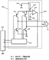
図1は、本発明の第1の実施の形態における衣類乾燥機の概略構成を示すブロック図、図2は、同衣類乾燥機の排水ポンプ駆動回路の回路図を示したものである。
(Embodiment 1)
FIG. 1 is a block diagram showing a schematic configuration of a clothes dryer according to the first embodiment of the present invention, and FIG. 2 is a circuit diagram of a drain pump driving circuit of the clothes dryer.
図1において、本実施の形態における衣類乾燥機は、衣類41を収納する乾燥庫42と、乾燥庫42の回転軸42aに直軸に接続され乾燥庫42を回転する乾燥庫モータ43と、ヒートポンプサイクル48を備え、ヒートポンプサイクル48は、圧縮機44と、熱交換器45、46とキャピラリチューブ47から構成されている。さらに、熱交換器45の上流側と乾燥庫42とは風路50で、熱交換器46の下流側と乾燥庫42とは風路A50aで夫々連通し、前記風路50及び風路A50a内で空気を循環移動させる送風手段51を設けている。
Referring to FIG. 1, a clothes dryer in the present embodiment includes a
なお、熱交換器45は、冷媒を蒸発させることにより、空気から冷媒に熱を吸い込ませる作用から蒸発器などとも呼ばれ、一方熱交換器46は、逆に冷媒から空気に熱を与える作用をするもので、凝縮器と言われることもあるが、特に使用する冷媒は各種のフロンなどに限定されるものではなく、例えば二酸化炭素(CO2)を超臨界状態として使用するものなどでも良く、ガスクーラーなどであってもかまわない。
The
そして、乾燥庫モータ43を駆動する第1の駆動回路55と、圧縮機44を駆動する第2の駆動回路56が接続されている。第1の整流回路58は、倍電圧形であって第1の駆動回路55に約250Vの直流電圧を供給し、第2の整流回路59も、やはり倍電圧形であるが第2の駆動回路56の方に230Vの直流電圧を供給するものとなっている。
A
さらに、本実施の形態においては、電源プラグ60が設けられており、電源高調波と端子雑音を抑えつつ、第1の整流回路58と第2の整流回路59に交流電源を供給する構成となっている。
Further, in the present embodiment, the
また、給水手段63が、水道管64および開閉により水道管64からの水を入れたり止めたりする給水弁65によって構成され、給水手段63から水が乾燥庫42に供給され、乾燥庫42内で衣類41の洗濯および脱水も行うものとなっている。排水弁68は、乾燥庫42の下部に設けられていて、閉状態では乾燥庫42内に水を蓄えて洗濯やすすぎが行われ、開状態になった場合には、乾燥庫42の内部から水を排水管69に捨て去るものとなっている。
Further, the water supply means 63 is constituted by a
衣類乾燥により乾燥庫42内が除湿され、その水分がヒートポンプサイクル48の熱交換器45が低温となっているため、湿った空気がそこで冷やされて結露水を発生するが、排水ポンプ70は、その結露水を排水するもので、直流12ボルトで動作する永久磁石、ブラシおよび整流子を有する小型の電動機71、電動機71により回転される第1の歯車72、第1の歯車72と嵌合し、第1の歯車72とは逆向きに回転する第2の歯車73、第1の歯車72と第2の歯車73を取り囲むケース74、およびその入り口側に設けたフィルタ75から構成され、ヒートポンプサイクル48からの結露水を貯める結露水溜め76から結露水を吸い上げて、一旦上側に押し上げ、オーバーフロー皿77に流し出した後に、改めてオーバーフロー管78を経て排水管69に合流するものとなっている。排水ポンプ駆動回路80は、排水ポンプ70を正方向および逆方向に駆動するものである。
Since the inside of the drying
図2において、12ボルトの直流電源86、PNP形のトランジスタ87、88、NPN形のトランジスタ89、90、正逆制御回路91を有しており、機器全体の制御を行うマイクロコンピュータ92からの信号により、排水ポンプ70の正方向の駆動、逆方向の駆動、および停止の制御を行う。
In FIG. 2, a 12-volt
すなわち、マイクロコンピュータ92の信号Aがハイ、Bがローとなる場合には、トランジスタ87、90がオンとなり、トランジスタ88、89がオフとなり、電動機71の電圧VMは、+11.5Vとなって正方向に回転し、結露水溜め76からフィルタ75を通して結露水を吸い出してオーバーフロー皿77に送り出すという動作が行われるものとなる。
That is, when the signal A of the
逆に、マイクロコンピュータ92の信号Aがロー、Bがハイとなる場合には、トランジスタ87、90がオフとなり、トランジスタ88、89がオンとなり、電動機71の電圧VMは、−11.5Vとなる。しかるに電動機71は供給される電圧の正負により回転の向きは反転するものとなるため、VMが負の場合には逆方向に回転するものとなる。
On the contrary, when the signal A of the
なお、信号Aと信号Bが共にローである場合には、トランジスタ87、88、89、90はすべてオフとなり、駆動されない状態となる。この時、排水ポンプ70内に水があれば、フィルタ75に詰まりかけていた異物は、フィルタ75からはがれて落ち、フィルタ75の浄化がなされるものとなる。
When both the signal A and the signal B are low, the
また、排水ポンプ70内の第1の歯車72、第2の歯車73の間およびそれらの回転部とケース74の間に挟まりかけている異物なども落ちて、自由に回転ができる状態となる。
In addition, foreign matter caught between the
図2において、過電流検知手段95は、排水ポンプ70の電動機71に供給される電流を検知するための2オームの抵抗96、コンパレータ97、11.6ボルトの直流電源98によって構成されており、通常の状態では抵抗96に流れる電流が200ミリアンペア以下であって抵抗96の電圧ドロップが0.4ボルト以下であり、コンパレータ97のプラス入力の方が低い電位となってC信号はローとなる。
In FIG. 2, the overcurrent detection means 95 is constituted by a 2-
ここで、排水ポンプ70の内部の回転部分にリントなどの異物が挟まって、電動機71がロック状態となった場合、およびフィルタ75にリントなどの異物がビッシリと詰まって水路がふさがれた場合については、いずれも電動機71のトルクが大となることから、電流も大となり、抵抗96に流れる電流が200ミリアンペアを超えるものとなる。
Here, when foreign matter such as lint is caught in the rotating portion inside the
発明者が測定したデータによれば、通常時には140ミリアンペアであったものが、ロック状態の場合には最大700ミリアンペア、また水路が完全に詰まった場合には、280ミリアンペアの電流値となった。 According to the data measured by the inventor, the current value was 140 milliamperes at normal times, but the maximum current value was 700 milliamperes in the locked state and 280 milliamperes when the water channel was completely blocked.
したがって、コンパレータ97は、プラス入力端子よりもマイナス入力端子の電位が下がることから、出力信号Cがハイとなりマイクロコンピュータ92に過電流である旨を出力するものとなる。
Therefore, since the potential of the negative input terminal is lower than that of the positive input terminal, the comparator 97 outputs the fact that the output signal C becomes high and the
本実施の形態では、マイクロコンピュータ92は、正回転期間に信号Cがハイとなった状態が200ミリ秒以上続いた場合には、一旦信号AとBを共にローとして停止させた後、信号Aをロー、Bをハイとして逆回転とする逆回転期間を2秒間設け、異物除去を行った後、1秒間の停止期間、正回転期間という順で制御していくものとなっている。
In the present embodiment, when the state in which the signal C is high during the normal rotation period continues for 200 milliseconds or more, the
このように、本実施の形態では、排水ポンプ70が詰まった場合、過電流検知手段95は排水ポンプ70に供給する電流値を検知して、その電流値が所定値を越え、詰まっていると判断された場合には、排水ポンプ70の駆動を停止し、その後所定時間逆方向に駆動する制御を行うものとなっている。
Thus, in the present embodiment, when the
なお、本実施の形態においては、排水ポンプ70として、第1の歯車72と第2の歯車73を持つ、いわゆるギアポンプなどと呼ばれるものを使用していることから、逆回転期間には水流の向きも逆となってフィルタ75に溜まった異物も除去できるという効果が得られるものとなっている。
In the present embodiment, since the
しかしながら、歯車を使用せず羽根車をケース内で回転させる形式の場合においては、若干状況が変化し、逆回転期間においても水流の向きは逆にはならないものとなり、また同時に電動機のトルクについてもロック時には増えるが、水路が詰まった場合にはトルクが減少して電流値は通常よりも小となるという傾向がある。よって過電流検知手段95によって検出できるのは、回転する羽根部分に異物が挟まったロック状態などとなり、その場合にも逆回転期間を設けることにより、異物の噛み込みは解けてロック状態が解除できることが多いことから極めて有効である。 However, in the case of the type in which the impeller is rotated in the case without using a gear, the situation changes slightly, and the direction of the water flow does not reverse during the reverse rotation period, and at the same time the torque of the motor Although it increases at the time of locking, when the water channel is clogged, the torque tends to decrease and the current value tends to be smaller than usual. Therefore, the overcurrent detection means 95 can detect a locked state in which foreign matter is caught between the rotating blades, and even in such a case, by providing a reverse rotation period, the foreign matter can be released and the locked state can be released. It is extremely effective because there are many.
(実施の形態2)
図3は、本発明の第2の実施の形態における衣類乾燥機の水位センサ部分の回路図を示している。本実施の形態は、結露水溜め76に蓄えられた結露水の水位を検知する水位センサ100を設けたもので、他の構成は、上記実施の形態と同一であり、その詳細な説明を省略する。
(Embodiment 2)
FIG. 3 shows a circuit diagram of the water level sensor portion of the clothes dryer in the second embodiment of the present invention. The present embodiment is provided with a
図3において、水位センサ100は、マイクロコンピュータ92のD端子から12キロヘルツのハイ、ローを繰り返す信号を受け、水位に応じた電圧をE信号として出力するものである。
In FIG. 3, a
水位センサ100は、結露水溜め76に蓄えられる結露水の水位がほぼ限度となる状態において結露水と接するように設けられた電極101、102と、雑音防止のためのコイル103、104と、抵抗105、106、107、108と、コンデンサ109、110、111、112と、NPN形のトランジスタ115と、ダイオード116、117、118と、絶縁トランス120とによって構成され、電極101、102間が空気中にある場合に信号Eの電位が3.5ボルト、また電極101、102間に結露水が触れた場合には、電極101、102間の抵抗値が数10キロオーム程度となることにより、信号Eへの出力アナログ電圧は1.0ボルト程度にまで低下するという特性を有するものとなっており、マイクロコンピュータ92のE信号がアナログ電圧として入力され、マイクロコンピュータ92内のソフトウェアによる処理で、アナログ電圧が1.7ボルト以下である場合には、電極101、102が結露水に浸っていると判断され、すなわち高水位信号を意味するものとなっている。
The
本実施の形態においては、図3に示した水位センサ100の周辺回路部分以外の構成については、実施例1と同等であり、通常の乾燥動作中においては、圧縮機44の駆動とともに、約5分に一回ずつ、各10秒間の間、排水ポンプ70は排水ポンプ駆動回路80によって正方向に駆動されることから、5分間に発生する分の結露水はほぼ完全に結露水溜め76から排水され、その結果、結露水溜め76に一時的に蓄えられる結露水の水位は、電極101、102の高さよりも低く、高水位信号が発せられるには至らないものとなっている。
In the present embodiment, the configuration other than the peripheral circuit portion of the
しかしながら、排水ポンプ70に、リントが絡まった場合などで、排水ポンプ70の機能が低下した場合には、通常の排水ポンプ70の運転では結露水が結露水溜め76から十分に排水されず、結露水溜め76の結露水の水位は徐々に上昇していくものとなり、やがて電極101、102の先端まで水面が達した時点で、水位センサ100から高水位信号が発せられ、マイクロコンピュータ92を経て、排水ポンプ70が10秒間の逆方向に駆動する期間を設けて、リントなどの異物の除去動作に入る。
However, if the function of the
なお、本実施の形態においては、絶縁トランス120を用いて電極101、102がマイクロコンピュータ92と電気的に絶縁された構成となっていることから、電極101、102からの雑音によるマイクロコンピュータ92の誤動作の防止や結露水を通しての感電の防止が容易にできるという効果を上げているものとなっているが、必ずしもこのような構成にする必要はなく、例えば絶縁トランス120無しで、電極101、102と所定の抵抗器の分圧を直接マイクロコンピュータ92に取り込む方法や、フロート(浮き)を設けて、結露水の水位が上昇した場合には、そのフロートが上に浮き上がって接点を閉じるなどの構成の水位センサとしてもかまわない。
In the present embodiment, since the
(実施の形態3)
図4は、本発明の第3の実施の形態における衣類乾燥機の排水ポンプ駆動回路80の動作波形図を示している。
(Embodiment 3)
FIG. 4 shows an operation waveform diagram of the drainage
本実施の形態は、排水ポンプ70を正方向および逆方向に駆動する排水ポンプ駆動回路80の動作波形が異なるだけで、その他の構成等は第1の実施の形態と同一なので、同一符号を付して、その詳細な説明を省略する。
This embodiment is different from the first embodiment only in the operation waveform of the drain
マイクロコンピュータ92からの信号A、Bが共にローの排水ポンプ70停止状態から、排水ポンプ70を駆動する際には、まずマイクロコンピュータ92からの信号Bのみがハイとなり、逆方向の駆動が1秒間行われ、その後信号Bがローに戻って1秒間の停止期間を経た後、今度は信号Aがハイとなるのを受け、排水ポンプ駆動回路80が正方向に10秒間駆動され、これによって排水ポンプ70の駆動を行い結露水の排水動作を行う。
When the
このように、排水ポンプ駆動回路80が、排水ポンプ70を正方向に駆動する正回転期間の直前に排水ポンプ70を所定時間逆方向に回転する逆回転期間を設けることにより、排水ポンプ70に挟まりそうになっている状態の異物を、逆回転期間で予め落としておき、異物が絡んでいない状態に整えておくことができるので、その後正回転期間において良好な排水動作が行われるものとなる。
As described above, the drain
(実施の形態4)
図5は、本発明の第4の実施の形態における衣類乾燥機の排水ポンプ駆動回路80の動作波形図を示している。
(Embodiment 4)
FIG. 5 shows an operation waveform diagram of the drainage
本実施の形態は、排水ポンプ70を正方向および逆方向に駆動する排水ポンプ駆動回路80の動作波形が異なるだけで、その他の構成等は第1の実施の形態と同一であり、詳細な説明を省略する。
The present embodiment is the same as the first embodiment except for the operation waveform of the drain
マイクロコンピュータ92からの信号A、Bが共にローの排水ポンプ70停止状態から、まずマイクロコンピュータ92からの信号Aがハイとなり、正方向の駆動が2秒間行われ、結露水の排水動作が開始され、その後信号Aがローに戻って0.5秒間の停止期間を経た後、今度は信号Bがハイとなるのを受け、排水ポンプ駆動回路80が逆方向に排水ポンプ70の駆動を1秒間行いリントなど異物除去動作に入る。
From the stop state of the
そして、その後また再び信号A、Bともにローの停止期間を0.5秒間経過した後、再度信号Aがハイとなる正回転期間を10秒間設けているため、残っている結露水を汲み出す動作が行われるものとなる。 After that, after a low stop period of 0.5 seconds has elapsed for both signals A and B again, a positive rotation period during which signal A goes high again is provided for 10 seconds, so that the remaining condensed water is pumped out. Will be done.
このように、排水ポンプ駆動回路80が、排水ポンプ70を正方向に駆動する正回転期間の最中に排水ポンプ70を所定時間逆方向に回転する構成とすることにより、排水ポンプ70内に有る水が逆流するので、排水ポンプ70の入り口付近に詰まりかけている異物を効果的に取り除き、良好な状態に持って行くことができる。
As described above, the drain
(実施の形態5)
図6は、本発明の第5の実施の形態における衣類乾燥機の排水ポンプ駆動回路80の動作波形図を示している。
(Embodiment 5)
FIG. 6 shows an operation waveform diagram of the drainage
本実施の形態は、排水ポンプ70を正方向および逆方向に駆動する排水ポンプ駆動回路80の動作波形が異なるだけで、その他の構成は、上記第1の実施の形態と同一なので説明を省略する。
In this embodiment, only the operation waveform of the drain
マイクロコンピュータ92からの信号A、Bが共にローの排水ポンプ70停止状態から、マイクロコンピュータ92からの信号Aがハイとなり、正方向の駆動が10秒間行われ、結露水の排水動作が行われ、その後信号Aがローに戻って1秒間の停止期間を経た後、今度は信号Bがハイとなるのを受け、排水ポンプ駆動回路80が逆方向に排水ポンプ70の駆動を1秒間行いリントなど異物除去動作に入る。
The signal A from the
このように、排水ポンプ駆動回路80が、排水ポンプ70を正方向に駆動する正回転期間の直後に排水ポンプ70を逆方向に回転する逆回転期間を設けることにより、正回転期間中に徐々に詰まりかけていた異物を一掃し、次回の排水ポンプ70動作が極めて良好に始められる状態としておくことができるものとなる。
In this way, the drain
(実施の形態6)
図7は、本発明の第6の実施の形態における衣類乾燥機のフローチャートを示している。
(Embodiment 6)
FIG. 7 shows a flowchart of the clothes dryer in the sixth embodiment of the present invention.
本実施の形態は、実施の形態1と同様、マイクロコンピュータ92から排水ポンプ駆動回路80に正方向、逆方向、停止の指令信号が送られるものとなっているが、マイクロコンピュータ92内のプログラムのフローチャートは、図7のようなものとなっており、その他の構成は、上記実施の形態と同一なので説明を省略する。
In the present embodiment, in the same manner as in the first embodiment, forward, reverse, and stop command signals are sent from the
すなわち、本実施の形態においては洗濯も行えるものとなっているため、機器の電源が投入された後、フローチャートの「開始」140からスタートするが、まず「コース選択」141で洗濯、脱水、乾燥の単独コース、あるいは全自動のコース選択を行う。 That is, in this embodiment, since washing can be performed, the apparatus starts from “Start” 140 in the flowchart after the device is turned on. First, “Course selection” 141 performs washing, dehydration, and drying. Single course or fully automatic course selection.
「洗濯」が選択された場合には、「洗濯ルーチン」142に入るが、これは給水弁65を開いてドラム状の乾燥庫42内に水を入れて乾燥庫モータ43によって乾燥庫42ごと回転させて洗い動作に入り、後に、排水弁68を開き、更に乾燥庫モータ43の速度を上げて遠心力による洗浄液の絞り動作を行った後、再度給水弁65を開放して今度はすすぎを同様の制御を行うものである。
When “Laundry” is selected, “Laundry routine” 142 is entered, which opens the
「洗濯ルーチン」142の終了後、および「コース選択」141で脱水が選択された場合には、「脱水ルーチン」143に進み、乾燥庫モータ43により乾燥庫42の速度を最終的に毎分1000回転にまで上昇させてしっかりと衣類の水分を絞り出し、「終了」144で動作を終えるものとなる。
After the completion of the “washing routine” 142 and when dehydration is selected in the “course selection” 141, the process proceeds to the “dehydration routine” 143, and the drying
「コース選択」141で、「乾燥」が選択された場合には、「乾燥ルーチン」146に入り、ヒートポンプサイクル48の圧縮機44が駆動され、同時に乾燥庫モータ43によるゆっくりとした乾燥庫42の間欠的な回転も合わせて行われ、衣類の乾燥動作が行われる。また、ここでは結露水を処理するため、排水ポンプ駆動回路80についても数分間隔で各10秒間の正方向の排水ポンプ70の駆動が行われ、結露水を結露水溜め76から汲み出すという動作も行う。
When “drying” is selected in “course selection” 141, “drying routine” 146 is entered, the compressor 44 of the
乾燥が終了した段階で「乾燥ルーチン」146が終了し、「逆回転ルーチン」147に入るが、ここで排水ポンプ駆動回路80は、排水ポンプ70を10秒間逆方向に駆動し、排水ポンプ70内の回転部分、およびフィルタ75に付着したリントなどの異物の除去動作を行う。ただし、10秒間とする必要が特にあるわけでもなく、要は排水ポンプ70の内部の機構的可動部分が、排水動作と逆の向きに僅かでも駆動されれば、異物除去の効果は発生してくるものとなることから、設計によって逆回転の回数、時間などを決めれば良い。
When the drying is finished, the “drying routine” 146 is finished and the “reverse rotation routine” 147 is entered. Here, the drain
「逆回転ルーチン」147が完了した時点で「終了」144に移り動作が完了する。なお、「コース選択」141にて、全自動コースが選択された場合には、「洗濯ルーチン」148、「脱水ルーチン」149の順に制御した後、「乾燥ルーチン」146、「逆回転ルーチン」147を行い、「終了」144に進むが、「洗濯ルーチン」148は、「洗濯ルーチン」142とほぼ同等、また「脱水ルーチン」149は「脱水ルーチン」143とほぼ同等の制御となる。 When the “reverse rotation routine” 147 is completed, the process proceeds to “end” 144 to complete the operation. When a fully automatic course is selected in “Course selection” 141, the “Laundry routine” 148 and the “Dehydration routine” 149 are controlled in this order, followed by the “Drying routine” 146 and the “Reverse rotation routine” 147. The “washing routine” 148 is substantially the same as the “washing routine” 142, and the “dehydration routine” 149 is substantially the same as the “dehydration routine” 143.
このように、本実施の形態では衣類乾燥機の乾燥動作を1回行う毎に、1回の排水ポンプ70の逆方向の回転を行わせることから、比較的簡単な構成で、リントなどの付着は排水ポンプ70やフィルタ75などから都度剥し出すことができ、常に結露水を良好に汲み出すことができるものとなる。
As described above, in this embodiment, since the
なお、本実施の形態においては、「コース選択」141において、洗濯や脱水が選択された場合には乾燥動作が行われず、「逆回転ルーチン」147も実行されないものとなっているが、実行させるようにしてもかまわない。また、「逆回転ルーチン」147は終了するまでのどの部分に挿入してもよく、また複数箇所に存在させてもかまわない。 In this embodiment, when “washing” or “dehydration” is selected in “course selection” 141, the drying operation is not performed and the “reverse rotation routine” 147 is not performed. It doesn't matter if you do. Further, the “reverse rotation routine” 147 may be inserted in any part until the end, or may exist in a plurality of places.
(実施の形態7)
図8は、本発明の第7の実施の形態における衣類乾燥機のフローチャートを示している。
(Embodiment 7)
FIG. 8 shows a flowchart of the clothes dryer in the seventh embodiment of the present invention.
本実施の形態も、実施の形態1と同様、マイクロコンピュータ92から排水ポンプ駆動回路80に正方向、逆方向、停止の指令信号が送られるものとなっているが、マイクロコンピュータ92内のプログラムのフローチャートは、図8のようなものとなっている。
In the present embodiment, as in the first embodiment, command signals for forward direction, reverse direction, and stop are sent from the
本実施の形態は、「運転回数カウント」150と「回数判定」151を設けたもので、他の構成は上記第6の実施の形態と同一であり、同一符号を付して詳細な説明を省略する。 The present embodiment is provided with “operation count” 150 and “number of times determination” 151, and other configurations are the same as those of the sixth embodiment, and detailed description will be given with the same reference numerals. Omitted.
本実施の形態では、マイクロコンピュータ92内に3ビットの不揮発カウンタを設定していて、「運転回数カウント」150において、不揮発カウンタを+1し、回数判定151では、不揮発カウンタの値が7(2進数で111)となった場合には「逆回転ルーチン」147を実行させ、7以外の場合にはそのまま「終了」144に移るものとなっている。
In this embodiment, a non-volatile counter of 3 bits is set in the
これにより、本実施の形態では、若干構成は複雑となるが、8回の乾燥動作回数に達した時に排水ポンプ70が逆回転されるものとなるが、異物の付着の可能性によって所定回数は8回以外にも適度に設定するなど設計によって可能である。
Thereby, in this embodiment, although the configuration is slightly complicated, the
(実施の形態8)
図9は、本発明の第8の実施の形態における衣類乾燥機のフローチャートを示している。本実施の形態においても、実施の形態1と同様、マイクロコンピュータ92から排水ポンプ駆動回路80に正方向、逆方向、停止の指令信号が送られるものとなっているが、マイクロコンピュータ92内のプログラムのフローチャートは、図9のようなものとなっている。
(Embodiment 8)
FIG. 9 shows a flowchart of the clothes dryer in the eighth embodiment of the present invention. Also in the present embodiment, as in the first embodiment, forward, reverse, and stop command signals are sent from the
本実施の形態は、運転時間カウント160と時間判定161を設けている他は、上記第6の実施の形態と同一であり、同一部分についての詳細な説明は省略する。
The present embodiment is the same as the sixth embodiment except that an operation time count 160 and a
本実施の形態では、マイクロコンピュータ92内に4ビットの不揮発カウンタを設定していて、「運転時間カウント」160においては、1時間の運転につき不揮発カウンタを+1し、「時間判定」161で、不揮発カウンタの値が15以上(2進数で1111、およびキャリーが出た場合)となった場合には「逆回転ルーチン」147を実行させるものとし、それ以外の場合にはそのまま「終了」144に移る用にしている。
In this embodiment, a 4-bit non-volatile counter is set in the
これにより、本実施の形態では、さらに若干構成は複雑となるが、16時間の乾燥動作時間に達した時に排水ポンプ70が逆回転されるので、運転時間に比例する形で排水ポンプ70の異物付着が進む場合など、合理的な排水ポンプ70の異物除去動作がなされるものとなる。
As a result, in this embodiment, the configuration is slightly more complicated. However, since the
本実施の形態においても、異物の付着の可能性によって所定時間を16時間以外にも適度に設定するなど設計によって可能である。 Also in the present embodiment, it is possible to design by setting the predetermined time appropriately other than 16 hours depending on the possibility of the adhesion of foreign matter.
以上の各実施の形態においては、乾燥庫42は回転軸を水平としているが、必ずしも水平の回転軸に限定されるものではなく、例えば一般に縦形と呼ばれるような垂直軸で脱水時に回転する乾燥庫を有するものや、回転軸を水平に対して、20〜30度程度傾斜して設け、衣類の出し入れが行いやすいようにしたものなどであってもかまわず、乾燥庫内に例えばパルセータなどの他の機構部品などの構成要素をさらに設けて洗濯時に効果的な洗濯ができるような構成にしたものであってもよい。
In each of the above embodiments, the drying
以上のように、本発明にかかる衣類乾燥機は、結露水を効果的に処理でき、設置場所の制約を受けないもので、家庭用、業務用の衣類乾燥機に広く適用できる。 As described above, the clothes dryer according to the present invention can effectively treat condensed water and is not subject to restrictions on the installation location, and can be widely applied to domestic and commercial clothes dryers.
42 乾燥庫
44 圧縮機
45、46 熱交換器
48 ヒートポンプサイクル
50 風路
50a 風路A
70 排水ポンプ
80 排水ポンプ駆動回路
95 過電流検知手段
100 水位センサ
42 Dryer 44
70
Claims (9)
Priority Applications (1)
| Application Number | Priority Date | Filing Date | Title |
|---|---|---|---|
| JP2004276839A JP2006087672A (en) | 2004-09-24 | 2004-09-24 | Clothes dryer |
Applications Claiming Priority (1)
| Application Number | Priority Date | Filing Date | Title |
|---|---|---|---|
| JP2004276839A JP2006087672A (en) | 2004-09-24 | 2004-09-24 | Clothes dryer |
Publications (1)
| Publication Number | Publication Date |
|---|---|
| JP2006087672A true JP2006087672A (en) | 2006-04-06 |
Family
ID=36229181
Family Applications (1)
| Application Number | Title | Priority Date | Filing Date |
|---|---|---|---|
| JP2004276839A Pending JP2006087672A (en) | 2004-09-24 | 2004-09-24 | Clothes dryer |
Country Status (1)
| Country | Link |
|---|---|
| JP (1) | JP2006087672A (en) |
Cited By (14)
| Publication number | Priority date | Publication date | Assignee | Title |
|---|---|---|---|---|
| JP2012241947A (en) * | 2011-05-17 | 2012-12-10 | Hitachi Appliances Inc | Pump motor control device |
| US8418377B2 (en) * | 2007-11-06 | 2013-04-16 | Bsh Bosch Und Siemens Hausgeraete Gmbh | Dryer with heat pump |
| EP2586904A1 (en) | 2011-10-31 | 2013-05-01 | Samsung Electronics Co., Ltd | Clothes dryer |
| KR20130047565A (en) | 2011-10-31 | 2013-05-08 | 삼성전자주식회사 | Clothes dryer |
| EP2881326A1 (en) * | 2013-12-06 | 2015-06-10 | The Boeing Company | Method, system, and device for liquid drainage |
| JP2015141863A (en) * | 2014-01-30 | 2015-08-03 | アイシン精機株式会社 | fuel cell system |
| JP2015220140A (en) * | 2014-05-19 | 2015-12-07 | 日本特殊陶業株式会社 | Device of controlling fuel cell system, and method of controlling fuel cell system |
| JP2016036482A (en) * | 2014-08-07 | 2016-03-22 | パナソニックIpマネジメント株式会社 | Dryer |
| CN105839370A (en) * | 2016-05-11 | 2016-08-10 | 无锡小天鹅股份有限公司 | Clothes dryer and drainage system thereof |
| CN105937167A (en) * | 2016-05-31 | 2016-09-14 | 无锡小天鹅股份有限公司 | Heat pump dryer or heat pump washing-drying integrated machine |
| US9988151B2 (en) | 2014-01-24 | 2018-06-05 | The Boeing Company | Dehumidification system for use in a vehicle and method of assembling thereof |
| WO2020050691A1 (en) * | 2018-09-06 | 2020-03-12 | 엘지전자 주식회사 | Drain pump driving apparatus and laundry processing machine comprising same |
| WO2021056892A1 (en) * | 2019-09-29 | 2021-04-01 | 无锡飞翎电子有限公司 | Laundry treatment device and control method therefor, and operation control apparatus and storage medium |
| CN113143161A (en) * | 2021-04-30 | 2021-07-23 | 华帝股份有限公司 | Clean discharge pump control method for preventing dirt blockage of dish washing machine and dish washing machine |
-
2004
- 2004-09-24 JP JP2004276839A patent/JP2006087672A/en active Pending
Cited By (29)
| Publication number | Priority date | Publication date | Assignee | Title |
|---|---|---|---|---|
| US8418377B2 (en) * | 2007-11-06 | 2013-04-16 | Bsh Bosch Und Siemens Hausgeraete Gmbh | Dryer with heat pump |
| JP2012241947A (en) * | 2011-05-17 | 2012-12-10 | Hitachi Appliances Inc | Pump motor control device |
| KR20200042447A (en) | 2011-10-31 | 2020-04-23 | 삼성전자주식회사 | Clothes Dryer |
| KR20130047565A (en) | 2011-10-31 | 2013-05-08 | 삼성전자주식회사 | Clothes dryer |
| KR20210006480A (en) | 2011-10-31 | 2021-01-18 | 삼성전자주식회사 | Clothes Dryer |
| KR102107230B1 (en) * | 2011-10-31 | 2020-05-07 | 삼성전자주식회사 | Clothes Dryer |
| KR101942493B1 (en) * | 2011-10-31 | 2019-01-25 | 삼성전자주식회사 | Clothes Dryer |
| EP2586904A1 (en) | 2011-10-31 | 2013-05-01 | Samsung Electronics Co., Ltd | Clothes dryer |
| KR20230049071A (en) | 2011-10-31 | 2023-04-12 | 삼성전자주식회사 | Clothes Dryer |
| KR20220035059A (en) | 2011-10-31 | 2022-03-21 | 삼성전자주식회사 | Clothes Dryer |
| KR102294426B1 (en) * | 2011-10-31 | 2021-08-30 | 삼성전자주식회사 | Clothes Dryer |
| KR102370628B1 (en) * | 2011-10-31 | 2022-03-07 | 삼성전자주식회사 | Clothes Dryer |
| KR20210110255A (en) | 2011-10-31 | 2021-09-07 | 삼성전자주식회사 | Clothes Dryer |
| KR20190011793A (en) | 2011-10-31 | 2019-02-07 | 삼성전자주식회사 | Clothes Dryer |
| RU2646011C2 (en) * | 2013-12-06 | 2018-02-28 | Зе Боинг Компани | Method, system and device for liquid draining |
| US11118808B2 (en) | 2013-12-06 | 2021-09-14 | The Boeing Company | Method, system, and device for liquid drainage |
| EP2881326A1 (en) * | 2013-12-06 | 2015-06-10 | The Boeing Company | Method, system, and device for liquid drainage |
| US9988151B2 (en) | 2014-01-24 | 2018-06-05 | The Boeing Company | Dehumidification system for use in a vehicle and method of assembling thereof |
| JP2015141863A (en) * | 2014-01-30 | 2015-08-03 | アイシン精機株式会社 | fuel cell system |
| JP2015220140A (en) * | 2014-05-19 | 2015-12-07 | 日本特殊陶業株式会社 | Device of controlling fuel cell system, and method of controlling fuel cell system |
| JP2016036482A (en) * | 2014-08-07 | 2016-03-22 | パナソニックIpマネジメント株式会社 | Dryer |
| CN105839370B (en) * | 2016-05-11 | 2018-03-13 | 无锡小天鹅股份有限公司 | The drainage system of dryer and dryer |
| CN105839370A (en) * | 2016-05-11 | 2016-08-10 | 无锡小天鹅股份有限公司 | Clothes dryer and drainage system thereof |
| CN105937167B (en) * | 2016-05-31 | 2018-04-20 | 无锡小天鹅股份有限公司 | Heat pump clothes dryer or heat pump washing-drying integral machine |
| CN105937167A (en) * | 2016-05-31 | 2016-09-14 | 无锡小天鹅股份有限公司 | Heat pump dryer or heat pump washing-drying integrated machine |
| WO2020050691A1 (en) * | 2018-09-06 | 2020-03-12 | 엘지전자 주식회사 | Drain pump driving apparatus and laundry processing machine comprising same |
| AU2019334749B2 (en) * | 2018-09-06 | 2023-03-30 | Lg Electronics Inc. | Drain pump driving apparatus and laundry processing machine comprising same |
| WO2021056892A1 (en) * | 2019-09-29 | 2021-04-01 | 无锡飞翎电子有限公司 | Laundry treatment device and control method therefor, and operation control apparatus and storage medium |
| CN113143161A (en) * | 2021-04-30 | 2021-07-23 | 华帝股份有限公司 | Clean discharge pump control method for preventing dirt blockage of dish washing machine and dish washing machine |
Similar Documents
| Publication | Publication Date | Title |
|---|---|---|
| KR101455774B1 (en) | Dryer and method of controlling cleaning operation thereof | |
| JP2006087672A (en) | Clothes dryer | |
| AU2005203177B2 (en) | Washing machine combined with dryer and controlling method thereof | |
| TWI360596B (en) | ||
| EP1698722A1 (en) | Washing machine and suds removal method thereof | |
| US8511324B2 (en) | Washing/drying machine | |
| KR20020044530A (en) | Drum washer | |
| JPH0698989A (en) | One-tub type washing machine | |
| EP3034669A1 (en) | Washing machine having drying function and method for controlling the same | |
| JP5053976B2 (en) | Washing and drying machine | |
| JP4991454B2 (en) | Washing and drying machine | |
| JP2008307416A (en) | Washing/drying machine | |
| JP2006000188A (en) | Washing/drying machine | |
| JP2010046124A (en) | Washing machine | |
| CN112831979B (en) | Laundry treating apparatus and drainage control method thereof | |
| JP2010240292A (en) | Drum type washing machine | |
| JP2008161396A (en) | Washing/drying machine | |
| JP2005137503A (en) | Clothes dryer | |
| JP2008307417A (en) | Washing/drying machine | |
| JP2005143533A (en) | Washing machine | |
| JP4543787B2 (en) | Washing and drying machine | |
| KR101287537B1 (en) | Washing machine and method to control spin-drying thereof | |
| JP2005143790A (en) | Washing/drying machine | |
| KR100441098B1 (en) | condensing water back draft preventing structure of drum wash and dry machine | |
| JP6400339B2 (en) | Clothes dryer |
Legal Events
| Date | Code | Title | Description |
|---|---|---|---|
| A621 | Written request for application examination |
Free format text: JAPANESE INTERMEDIATE CODE: A621 Effective date: 20070614 |
|
| RD01 | Notification of change of attorney |
Free format text: JAPANESE INTERMEDIATE CODE: A7421 Effective date: 20070712 |
|
| A977 | Report on retrieval |
Free format text: JAPANESE INTERMEDIATE CODE: A971007 Effective date: 20081111 |
|
| A131 | Notification of reasons for refusal |
Free format text: JAPANESE INTERMEDIATE CODE: A131 Effective date: 20081118 |
|
| A521 | Written amendment |
Free format text: JAPANESE INTERMEDIATE CODE: A523 Effective date: 20090116 |
|
| A131 | Notification of reasons for refusal |
Free format text: JAPANESE INTERMEDIATE CODE: A131 Effective date: 20090210 |
|
| A02 | Decision of refusal |
Free format text: JAPANESE INTERMEDIATE CODE: A02 Effective date: 20090818 |