JP2006079110A - Distorted helix effect electro-optic device and ferroelectric liquid crystal composition used therefor - Google Patents
Distorted helix effect electro-optic device and ferroelectric liquid crystal composition used therefor Download PDFInfo
- Publication number
- JP2006079110A JP2006079110A JP2005285568A JP2005285568A JP2006079110A JP 2006079110 A JP2006079110 A JP 2006079110A JP 2005285568 A JP2005285568 A JP 2005285568A JP 2005285568 A JP2005285568 A JP 2005285568A JP 2006079110 A JP2006079110 A JP 2006079110A
- Authority
- JP
- Japan
- Prior art keywords
- pitch
- phase
- liquid crystal
- flc
- ferroelectric liquid
- Prior art date
- Legal status (The legal status is an assumption and is not a legal conclusion. Google has not performed a legal analysis and makes no representation as to the accuracy of the status listed.)
- Withdrawn
Links
- 239000005262 ferroelectric liquid crystals (FLCs) Substances 0.000 title abstract description 253
- 239000000203 mixture Substances 0.000 title abstract description 158
- 230000000694 effects Effects 0.000 title abstract description 17
- 230000003287 optical effect Effects 0.000 abstract description 35
- 230000004044 response Effects 0.000 abstract description 11
- 210000002858 crystal cell Anatomy 0.000 abstract description 5
- 239000011295 pitch Substances 0.000 description 246
- 210000004027 cell Anatomy 0.000 description 147
- 239000004990 Smectic liquid crystal Substances 0.000 description 93
- 239000002019 doping agent Substances 0.000 description 67
- 125000004432 carbon atom Chemical group C* 0.000 description 66
- 230000007704 transition Effects 0.000 description 40
- 150000001875 compounds Chemical class 0.000 description 34
- 238000000034 method Methods 0.000 description 33
- 125000000217 alkyl group Chemical group 0.000 description 32
- 239000000463 material Substances 0.000 description 23
- 125000004430 oxygen atom Chemical group O* 0.000 description 21
- 125000001140 1,4-phenylene group Chemical group [H]C1=C([H])C([*:2])=C([H])C([H])=C1[*:1] 0.000 description 19
- 230000008859 change Effects 0.000 description 17
- 125000002252 acyl group Chemical group 0.000 description 15
- 230000005684 electric field Effects 0.000 description 15
- 230000010287 polarization Effects 0.000 description 15
- 125000003342 alkenyl group Chemical group 0.000 description 14
- 239000004677 Nylon Substances 0.000 description 12
- 229920001778 nylon Polymers 0.000 description 12
- 230000002269 spontaneous effect Effects 0.000 description 11
- 125000004434 sulfur atom Chemical group 0.000 description 11
- 125000005103 alkyl silyl group Chemical group 0.000 description 10
- 229910052799 carbon Inorganic materials 0.000 description 10
- 230000007423 decrease Effects 0.000 description 10
- 230000001747 exhibiting effect Effects 0.000 description 10
- 239000004973 liquid crystal related substance Substances 0.000 description 9
- 125000004433 nitrogen atom Chemical group N* 0.000 description 9
- OKTJSMMVPCPJKN-UHFFFAOYSA-N Carbon Chemical compound [C] OKTJSMMVPCPJKN-UHFFFAOYSA-N 0.000 description 8
- 238000010587 phase diagram Methods 0.000 description 8
- 125000000753 cycloalkyl group Chemical group 0.000 description 6
- 238000004519 manufacturing process Methods 0.000 description 6
- 230000008569 process Effects 0.000 description 6
- 125000004955 1,4-cyclohexylene group Chemical group [H]C1([H])C([H])([H])C([H])([*:1])C([H])([H])C([H])([H])C1([H])[*:2] 0.000 description 5
- 230000005540 biological transmission Effects 0.000 description 5
- 125000000392 cycloalkenyl group Chemical group 0.000 description 5
- 230000001939 inductive effect Effects 0.000 description 5
- 229920000642 polymer Polymers 0.000 description 5
- 238000004381 surface treatment Methods 0.000 description 5
- 238000012360 testing method Methods 0.000 description 5
- 229910052736 halogen Inorganic materials 0.000 description 4
- 150000002367 halogens Chemical class 0.000 description 4
- 230000006698 induction Effects 0.000 description 4
- 238000005259 measurement Methods 0.000 description 4
- 238000012986 modification Methods 0.000 description 4
- 230000004048 modification Effects 0.000 description 4
- 229910052717 sulfur Inorganic materials 0.000 description 4
- -1 terphenyl diesters Chemical class 0.000 description 4
- 238000001816 cooling Methods 0.000 description 3
- 230000003993 interaction Effects 0.000 description 3
- 230000006641 stabilisation Effects 0.000 description 3
- 238000011105 stabilization Methods 0.000 description 3
- 125000005407 trans-1,4-cyclohexylene group Chemical group [H]C1([H])C([H])([H])[C@]([H])([*:2])C([H])([H])C([H])([H])[C@@]1([H])[*:1] 0.000 description 3
- OXPDQFOKSZYEMJ-UHFFFAOYSA-N 2-phenylpyrimidine Chemical compound C1=CC=CC=C1C1=NC=CC=N1 OXPDQFOKSZYEMJ-UHFFFAOYSA-N 0.000 description 2
- 238000012935 Averaging Methods 0.000 description 2
- RTZKZFJDLAIYFH-UHFFFAOYSA-N Diethyl ether Chemical compound CCOCC RTZKZFJDLAIYFH-UHFFFAOYSA-N 0.000 description 2
- 239000004952 Polyamide Substances 0.000 description 2
- 239000004642 Polyimide Substances 0.000 description 2
- 229920000297 Rayon Polymers 0.000 description 2
- 238000013459 approach Methods 0.000 description 2
- 125000004122 cyclic group Chemical group 0.000 description 2
- 230000003247 decreasing effect Effects 0.000 description 2
- 230000008021 deposition Effects 0.000 description 2
- 238000010586 diagram Methods 0.000 description 2
- 239000004744 fabric Substances 0.000 description 2
- 230000005621 ferroelectricity Effects 0.000 description 2
- AMGQUBHHOARCQH-UHFFFAOYSA-N indium;oxotin Chemical compound [In].[Sn]=O AMGQUBHHOARCQH-UHFFFAOYSA-N 0.000 description 2
- 229910052751 metal Inorganic materials 0.000 description 2
- 239000002184 metal Substances 0.000 description 2
- 238000000819 phase cycle Methods 0.000 description 2
- 229920002647 polyamide Polymers 0.000 description 2
- 229920001721 polyimide Polymers 0.000 description 2
- 239000002964 rayon Substances 0.000 description 2
- 230000004043 responsiveness Effects 0.000 description 2
- LMBFAGIMSUYTBN-MPZNNTNKSA-N teixobactin Chemical compound C([C@H](C(=O)N[C@@H]([C@@H](C)CC)C(=O)N[C@@H](CO)C(=O)N[C@H](CCC(N)=O)C(=O)N[C@H]([C@@H](C)CC)C(=O)N[C@@H]([C@@H](C)CC)C(=O)N[C@@H](CO)C(=O)N[C@H]1C(N[C@@H](C)C(=O)N[C@@H](C[C@@H]2NC(=N)NC2)C(=O)N[C@H](C(=O)O[C@H]1C)[C@@H](C)CC)=O)NC)C1=CC=CC=C1 LMBFAGIMSUYTBN-MPZNNTNKSA-N 0.000 description 2
- 238000011282 treatment Methods 0.000 description 2
- 239000004988 Nematic liquid crystal Substances 0.000 description 1
- 230000009471 action Effects 0.000 description 1
- 230000002411 adverse Effects 0.000 description 1
- 150000001336 alkenes Chemical class 0.000 description 1
- 230000004075 alteration Effects 0.000 description 1
- 125000003118 aryl group Chemical group 0.000 description 1
- 238000003556 assay Methods 0.000 description 1
- 125000004429 atom Chemical group 0.000 description 1
- 230000004323 axial length Effects 0.000 description 1
- 230000001680 brushing effect Effects 0.000 description 1
- 239000003795 chemical substances by application Substances 0.000 description 1
- 238000010276 construction Methods 0.000 description 1
- 238000007796 conventional method Methods 0.000 description 1
- 125000004956 cyclohexylene group Chemical group 0.000 description 1
- 230000007547 defect Effects 0.000 description 1
- 239000007772 electrode material Substances 0.000 description 1
- 150000002148 esters Chemical class 0.000 description 1
- 239000011521 glass Substances 0.000 description 1
- 238000010438 heat treatment Methods 0.000 description 1
- 239000004615 ingredient Substances 0.000 description 1
- 229910052500 inorganic mineral Inorganic materials 0.000 description 1
- OOYGSFOGFJDDHP-KMCOLRRFSA-N kanamycin A sulfate Chemical group OS(O)(=O)=O.O[C@@H]1[C@@H](O)[C@H](O)[C@@H](CN)O[C@@H]1O[C@H]1[C@H](O)[C@@H](O[C@@H]2[C@@H]([C@@H](N)[C@H](O)[C@@H](CO)O2)O)[C@H](N)C[C@@H]1N OOYGSFOGFJDDHP-KMCOLRRFSA-N 0.000 description 1
- 239000011707 mineral Substances 0.000 description 1
- 238000002156 mixing Methods 0.000 description 1
- 239000011306 natural pitch Substances 0.000 description 1
- 229910052757 nitrogen Inorganic materials 0.000 description 1
- 229910052698 phosphorus Inorganic materials 0.000 description 1
- 239000004033 plastic Substances 0.000 description 1
- 230000008092 positive effect Effects 0.000 description 1
- 238000002360 preparation method Methods 0.000 description 1
- 238000012545 processing Methods 0.000 description 1
- 150000003230 pyrimidines Chemical class 0.000 description 1
- 238000001028 reflection method Methods 0.000 description 1
- 238000002310 reflectometry Methods 0.000 description 1
- 238000011160 research Methods 0.000 description 1
- 238000004904 shortening Methods 0.000 description 1
- 125000005353 silylalkyl group Chemical group 0.000 description 1
- 125000006850 spacer group Chemical group 0.000 description 1
- 238000001228 spectrum Methods 0.000 description 1
- 238000010561 standard procedure Methods 0.000 description 1
- 238000006467 substitution reaction Methods 0.000 description 1
- 230000001629 suppression Effects 0.000 description 1
- 150000007970 thio esters Chemical class 0.000 description 1
- 150000003568 thioethers Chemical class 0.000 description 1
- XOLBLPGZBRYERU-UHFFFAOYSA-N tin dioxide Chemical compound O=[Sn]=O XOLBLPGZBRYERU-UHFFFAOYSA-N 0.000 description 1
- 229910001887 tin oxide Inorganic materials 0.000 description 1
Images

Classifications
-
- C—CHEMISTRY; METALLURGY
- C07—ORGANIC CHEMISTRY
- C07C—ACYCLIC OR CARBOCYCLIC COMPOUNDS
- C07C69/00—Esters of carboxylic acids; Esters of carbonic or haloformic acids
- C07C69/76—Esters of carboxylic acids having a carboxyl group bound to a carbon atom of a six-membered aromatic ring
- C07C69/84—Esters of carboxylic acids having a carboxyl group bound to a carbon atom of a six-membered aromatic ring of monocyclic hydroxy carboxylic acids, the hydroxy groups and the carboxyl groups of which are bound to carbon atoms of a six-membered aromatic ring
- C07C69/92—Esters of carboxylic acids having a carboxyl group bound to a carbon atom of a six-membered aromatic ring of monocyclic hydroxy carboxylic acids, the hydroxy groups and the carboxyl groups of which are bound to carbon atoms of a six-membered aromatic ring with etherified hydroxyl groups
-
- G—PHYSICS
- G02—OPTICS
- G02F—OPTICAL DEVICES OR ARRANGEMENTS FOR THE CONTROL OF LIGHT BY MODIFICATION OF THE OPTICAL PROPERTIES OF THE MEDIA OF THE ELEMENTS INVOLVED THEREIN; NON-LINEAR OPTICS; FREQUENCY-CHANGING OF LIGHT; OPTICAL LOGIC ELEMENTS; OPTICAL ANALOGUE/DIGITAL CONVERTERS
- G02F1/00—Devices or arrangements for the control of the intensity, colour, phase, polarisation or direction of light arriving from an independent light source, e.g. switching, gating or modulating; Non-linear optics
- G02F1/01—Devices or arrangements for the control of the intensity, colour, phase, polarisation or direction of light arriving from an independent light source, e.g. switching, gating or modulating; Non-linear optics for the control of the intensity, phase, polarisation or colour
- G02F1/13—Devices or arrangements for the control of the intensity, colour, phase, polarisation or direction of light arriving from an independent light source, e.g. switching, gating or modulating; Non-linear optics for the control of the intensity, phase, polarisation or colour based on liquid crystals, e.g. single liquid crystal display cells
-
- C—CHEMISTRY; METALLURGY
- C07—ORGANIC CHEMISTRY
- C07D—HETEROCYCLIC COMPOUNDS
- C07D213/00—Heterocyclic compounds containing six-membered rings, not condensed with other rings, with one nitrogen atom as the only ring hetero atom and three or more double bonds between ring members or between ring members and non-ring members
- C07D213/02—Heterocyclic compounds containing six-membered rings, not condensed with other rings, with one nitrogen atom as the only ring hetero atom and three or more double bonds between ring members or between ring members and non-ring members having three double bonds between ring members or between ring members and non-ring members
- C07D213/04—Heterocyclic compounds containing six-membered rings, not condensed with other rings, with one nitrogen atom as the only ring hetero atom and three or more double bonds between ring members or between ring members and non-ring members having three double bonds between ring members or between ring members and non-ring members having no bond between the ring nitrogen atom and a non-ring member or having only hydrogen or carbon atoms directly attached to the ring nitrogen atom
- C07D213/24—Heterocyclic compounds containing six-membered rings, not condensed with other rings, with one nitrogen atom as the only ring hetero atom and three or more double bonds between ring members or between ring members and non-ring members having three double bonds between ring members or between ring members and non-ring members having no bond between the ring nitrogen atom and a non-ring member or having only hydrogen or carbon atoms directly attached to the ring nitrogen atom with substituted hydrocarbon radicals attached to ring carbon atoms
- C07D213/28—Radicals substituted by singly-bound oxygen or sulphur atoms
- C07D213/30—Oxygen atoms
-
- C—CHEMISTRY; METALLURGY
- C07—ORGANIC CHEMISTRY
- C07D—HETEROCYCLIC COMPOUNDS
- C07D213/00—Heterocyclic compounds containing six-membered rings, not condensed with other rings, with one nitrogen atom as the only ring hetero atom and three or more double bonds between ring members or between ring members and non-ring members
- C07D213/02—Heterocyclic compounds containing six-membered rings, not condensed with other rings, with one nitrogen atom as the only ring hetero atom and three or more double bonds between ring members or between ring members and non-ring members having three double bonds between ring members or between ring members and non-ring members
- C07D213/04—Heterocyclic compounds containing six-membered rings, not condensed with other rings, with one nitrogen atom as the only ring hetero atom and three or more double bonds between ring members or between ring members and non-ring members having three double bonds between ring members or between ring members and non-ring members having no bond between the ring nitrogen atom and a non-ring member or having only hydrogen or carbon atoms directly attached to the ring nitrogen atom
- C07D213/60—Heterocyclic compounds containing six-membered rings, not condensed with other rings, with one nitrogen atom as the only ring hetero atom and three or more double bonds between ring members or between ring members and non-ring members having three double bonds between ring members or between ring members and non-ring members having no bond between the ring nitrogen atom and a non-ring member or having only hydrogen or carbon atoms directly attached to the ring nitrogen atom with hetero atoms or with carbon atoms having three bonds to hetero atoms with at the most one bond to halogen, e.g. ester or nitrile radicals, directly attached to ring carbon atoms
- C07D213/62—Oxygen or sulfur atoms
- C07D213/63—One oxygen atom
- C07D213/64—One oxygen atom attached in position 2 or 6
-
- C—CHEMISTRY; METALLURGY
- C07—ORGANIC CHEMISTRY
- C07D—HETEROCYCLIC COMPOUNDS
- C07D213/00—Heterocyclic compounds containing six-membered rings, not condensed with other rings, with one nitrogen atom as the only ring hetero atom and three or more double bonds between ring members or between ring members and non-ring members
- C07D213/02—Heterocyclic compounds containing six-membered rings, not condensed with other rings, with one nitrogen atom as the only ring hetero atom and three or more double bonds between ring members or between ring members and non-ring members having three double bonds between ring members or between ring members and non-ring members
- C07D213/04—Heterocyclic compounds containing six-membered rings, not condensed with other rings, with one nitrogen atom as the only ring hetero atom and three or more double bonds between ring members or between ring members and non-ring members having three double bonds between ring members or between ring members and non-ring members having no bond between the ring nitrogen atom and a non-ring member or having only hydrogen or carbon atoms directly attached to the ring nitrogen atom
- C07D213/60—Heterocyclic compounds containing six-membered rings, not condensed with other rings, with one nitrogen atom as the only ring hetero atom and three or more double bonds between ring members or between ring members and non-ring members having three double bonds between ring members or between ring members and non-ring members having no bond between the ring nitrogen atom and a non-ring member or having only hydrogen or carbon atoms directly attached to the ring nitrogen atom with hetero atoms or with carbon atoms having three bonds to hetero atoms with at the most one bond to halogen, e.g. ester or nitrile radicals, directly attached to ring carbon atoms
- C07D213/62—Oxygen or sulfur atoms
- C07D213/63—One oxygen atom
- C07D213/65—One oxygen atom attached in position 3 or 5
-
- C—CHEMISTRY; METALLURGY
- C07—ORGANIC CHEMISTRY
- C07D—HETEROCYCLIC COMPOUNDS
- C07D239/00—Heterocyclic compounds containing 1,3-diazine or hydrogenated 1,3-diazine rings
- C07D239/02—Heterocyclic compounds containing 1,3-diazine or hydrogenated 1,3-diazine rings not condensed with other rings
- C07D239/24—Heterocyclic compounds containing 1,3-diazine or hydrogenated 1,3-diazine rings not condensed with other rings having three or more double bonds between ring members or between ring members and non-ring members
- C07D239/26—Heterocyclic compounds containing 1,3-diazine or hydrogenated 1,3-diazine rings not condensed with other rings having three or more double bonds between ring members or between ring members and non-ring members with only hydrogen atoms, hydrocarbon or substituted hydrocarbon radicals, directly attached to ring carbon atoms
-
- C—CHEMISTRY; METALLURGY
- C07—ORGANIC CHEMISTRY
- C07D—HETEROCYCLIC COMPOUNDS
- C07D239/00—Heterocyclic compounds containing 1,3-diazine or hydrogenated 1,3-diazine rings
- C07D239/02—Heterocyclic compounds containing 1,3-diazine or hydrogenated 1,3-diazine rings not condensed with other rings
- C07D239/24—Heterocyclic compounds containing 1,3-diazine or hydrogenated 1,3-diazine rings not condensed with other rings having three or more double bonds between ring members or between ring members and non-ring members
- C07D239/28—Heterocyclic compounds containing 1,3-diazine or hydrogenated 1,3-diazine rings not condensed with other rings having three or more double bonds between ring members or between ring members and non-ring members with hetero atoms or with carbon atoms having three bonds to hetero atoms with at the most one bond to halogen, directly attached to ring carbon atoms
- C07D239/32—One oxygen, sulfur or nitrogen atom
- C07D239/34—One oxygen atom
-
- C—CHEMISTRY; METALLURGY
- C07—ORGANIC CHEMISTRY
- C07D—HETEROCYCLIC COMPOUNDS
- C07D239/00—Heterocyclic compounds containing 1,3-diazine or hydrogenated 1,3-diazine rings
- C07D239/02—Heterocyclic compounds containing 1,3-diazine or hydrogenated 1,3-diazine rings not condensed with other rings
- C07D239/24—Heterocyclic compounds containing 1,3-diazine or hydrogenated 1,3-diazine rings not condensed with other rings having three or more double bonds between ring members or between ring members and non-ring members
- C07D239/28—Heterocyclic compounds containing 1,3-diazine or hydrogenated 1,3-diazine rings not condensed with other rings having three or more double bonds between ring members or between ring members and non-ring members with hetero atoms or with carbon atoms having three bonds to hetero atoms with at the most one bond to halogen, directly attached to ring carbon atoms
- C07D239/32—One oxygen, sulfur or nitrogen atom
- C07D239/38—One sulfur atom
-
- C—CHEMISTRY; METALLURGY
- C07—ORGANIC CHEMISTRY
- C07D—HETEROCYCLIC COMPOUNDS
- C07D303/00—Compounds containing three-membered rings having one oxygen atom as the only ring hetero atom
- C07D303/02—Compounds containing oxirane rings
- C07D303/12—Compounds containing oxirane rings with hydrocarbon radicals, substituted by singly or doubly bound oxygen atoms
- C07D303/18—Compounds containing oxirane rings with hydrocarbon radicals, substituted by singly or doubly bound oxygen atoms by etherified hydroxyl radicals
- C07D303/20—Ethers with hydroxy compounds containing no oxirane rings
- C07D303/24—Ethers with hydroxy compounds containing no oxirane rings with polyhydroxy compounds
-
- C—CHEMISTRY; METALLURGY
- C07—ORGANIC CHEMISTRY
- C07D—HETEROCYCLIC COMPOUNDS
- C07D405/00—Heterocyclic compounds containing both one or more hetero rings having oxygen atoms as the only ring hetero atoms, and one or more rings having nitrogen as the only ring hetero atom
- C07D405/02—Heterocyclic compounds containing both one or more hetero rings having oxygen atoms as the only ring hetero atoms, and one or more rings having nitrogen as the only ring hetero atom containing two hetero rings
- C07D405/12—Heterocyclic compounds containing both one or more hetero rings having oxygen atoms as the only ring hetero atoms, and one or more rings having nitrogen as the only ring hetero atom containing two hetero rings linked by a chain containing hetero atoms as chain links
-
- C—CHEMISTRY; METALLURGY
- C09—DYES; PAINTS; POLISHES; NATURAL RESINS; ADHESIVES; COMPOSITIONS NOT OTHERWISE PROVIDED FOR; APPLICATIONS OF MATERIALS NOT OTHERWISE PROVIDED FOR
- C09K—MATERIALS FOR MISCELLANEOUS APPLICATIONS, NOT PROVIDED FOR ELSEWHERE
- C09K19/00—Liquid crystal materials
- C09K19/02—Liquid crystal materials characterised by optical, electrical or physical properties of the components, in general
- C09K19/0225—Ferroelectric
-
- C—CHEMISTRY; METALLURGY
- C09—DYES; PAINTS; POLISHES; NATURAL RESINS; ADHESIVES; COMPOSITIONS NOT OTHERWISE PROVIDED FOR; APPLICATIONS OF MATERIALS NOT OTHERWISE PROVIDED FOR
- C09K—MATERIALS FOR MISCELLANEOUS APPLICATIONS, NOT PROVIDED FOR ELSEWHERE
- C09K19/00—Liquid crystal materials
- C09K19/04—Liquid crystal materials characterised by the chemical structure of the liquid crystal components, e.g. by a specific unit
- C09K19/06—Non-steroidal liquid crystal compounds
- C09K19/08—Non-steroidal liquid crystal compounds containing at least two non-condensed rings
- C09K19/10—Non-steroidal liquid crystal compounds containing at least two non-condensed rings containing at least two benzene rings
- C09K19/12—Non-steroidal liquid crystal compounds containing at least two non-condensed rings containing at least two benzene rings at least two benzene rings directly linked, e.g. biphenyls
- C09K19/126—Compounds containing at least one asymmetric carbon atom
-
- C—CHEMISTRY; METALLURGY
- C09—DYES; PAINTS; POLISHES; NATURAL RESINS; ADHESIVES; COMPOSITIONS NOT OTHERWISE PROVIDED FOR; APPLICATIONS OF MATERIALS NOT OTHERWISE PROVIDED FOR
- C09K—MATERIALS FOR MISCELLANEOUS APPLICATIONS, NOT PROVIDED FOR ELSEWHERE
- C09K19/00—Liquid crystal materials
- C09K19/04—Liquid crystal materials characterised by the chemical structure of the liquid crystal components, e.g. by a specific unit
- C09K19/06—Non-steroidal liquid crystal compounds
- C09K19/08—Non-steroidal liquid crystal compounds containing at least two non-condensed rings
- C09K19/10—Non-steroidal liquid crystal compounds containing at least two non-condensed rings containing at least two benzene rings
- C09K19/20—Non-steroidal liquid crystal compounds containing at least two non-condensed rings containing at least two benzene rings linked by a chain containing carbon and oxygen atoms as chain links, e.g. esters or ethers
- C09K19/2007—Non-steroidal liquid crystal compounds containing at least two non-condensed rings containing at least two benzene rings linked by a chain containing carbon and oxygen atoms as chain links, e.g. esters or ethers the chain containing -COO- or -OCO- groups
- C09K19/2021—Compounds containing at least one asymmetric carbon atom
-
- C—CHEMISTRY; METALLURGY
- C09—DYES; PAINTS; POLISHES; NATURAL RESINS; ADHESIVES; COMPOSITIONS NOT OTHERWISE PROVIDED FOR; APPLICATIONS OF MATERIALS NOT OTHERWISE PROVIDED FOR
- C09K—MATERIALS FOR MISCELLANEOUS APPLICATIONS, NOT PROVIDED FOR ELSEWHERE
- C09K19/00—Liquid crystal materials
- C09K19/04—Liquid crystal materials characterised by the chemical structure of the liquid crystal components, e.g. by a specific unit
- C09K19/06—Non-steroidal liquid crystal compounds
- C09K19/34—Non-steroidal liquid crystal compounds containing at least one heterocyclic ring
- C09K19/3441—Non-steroidal liquid crystal compounds containing at least one heterocyclic ring having nitrogen as hetero atom
-
- C—CHEMISTRY; METALLURGY
- C09—DYES; PAINTS; POLISHES; NATURAL RESINS; ADHESIVES; COMPOSITIONS NOT OTHERWISE PROVIDED FOR; APPLICATIONS OF MATERIALS NOT OTHERWISE PROVIDED FOR
- C09K—MATERIALS FOR MISCELLANEOUS APPLICATIONS, NOT PROVIDED FOR ELSEWHERE
- C09K19/00—Liquid crystal materials
- C09K19/52—Liquid crystal materials characterised by components which are not liquid crystals, e.g. additives with special physical aspect: solvents, solid particles
- C09K19/58—Dopants or charge transfer agents
- C09K19/586—Optically active dopants; chiral dopants
- C09K19/588—Heterocyclic compounds
-
- G—PHYSICS
- G02—OPTICS
- G02F—OPTICAL DEVICES OR ARRANGEMENTS FOR THE CONTROL OF LIGHT BY MODIFICATION OF THE OPTICAL PROPERTIES OF THE MEDIA OF THE ELEMENTS INVOLVED THEREIN; NON-LINEAR OPTICS; FREQUENCY-CHANGING OF LIGHT; OPTICAL LOGIC ELEMENTS; OPTICAL ANALOGUE/DIGITAL CONVERTERS
- G02F1/00—Devices or arrangements for the control of the intensity, colour, phase, polarisation or direction of light arriving from an independent light source, e.g. switching, gating or modulating; Non-linear optics
- G02F1/01—Devices or arrangements for the control of the intensity, colour, phase, polarisation or direction of light arriving from an independent light source, e.g. switching, gating or modulating; Non-linear optics for the control of the intensity, phase, polarisation or colour
- G02F1/13—Devices or arrangements for the control of the intensity, colour, phase, polarisation or direction of light arriving from an independent light source, e.g. switching, gating or modulating; Non-linear optics for the control of the intensity, phase, polarisation or colour based on liquid crystals, e.g. single liquid crystal display cells
- G02F1/137—Devices or arrangements for the control of the intensity, colour, phase, polarisation or direction of light arriving from an independent light source, e.g. switching, gating or modulating; Non-linear optics for the control of the intensity, phase, polarisation or colour based on liquid crystals, e.g. single liquid crystal display cells characterised by the electro-optical or magneto-optical effect, e.g. field-induced phase transition, orientation effect, guest-host interaction or dynamic scattering
- G02F1/139—Devices or arrangements for the control of the intensity, colour, phase, polarisation or direction of light arriving from an independent light source, e.g. switching, gating or modulating; Non-linear optics for the control of the intensity, phase, polarisation or colour based on liquid crystals, e.g. single liquid crystal display cells characterised by the electro-optical or magneto-optical effect, e.g. field-induced phase transition, orientation effect, guest-host interaction or dynamic scattering based on orientation effects in which the liquid crystal remains transparent
- G02F1/141—Devices or arrangements for the control of the intensity, colour, phase, polarisation or direction of light arriving from an independent light source, e.g. switching, gating or modulating; Non-linear optics for the control of the intensity, phase, polarisation or colour based on liquid crystals, e.g. single liquid crystal display cells characterised by the electro-optical or magneto-optical effect, e.g. field-induced phase transition, orientation effect, guest-host interaction or dynamic scattering based on orientation effects in which the liquid crystal remains transparent using ferroelectric liquid crystals
- G02F1/1414—Deformed helix ferroelectric [DHL]
Landscapes
- Chemical & Material Sciences (AREA)
- Organic Chemistry (AREA)
- Crystallography & Structural Chemistry (AREA)
- Engineering & Computer Science (AREA)
- Materials Engineering (AREA)
- Physics & Mathematics (AREA)
- Nonlinear Science (AREA)
- General Physics & Mathematics (AREA)
- Optics & Photonics (AREA)
- Liquid Crystal Substances (AREA)
- Liquid Crystal (AREA)
Abstract
Description
本発明は、強誘電性液晶(以下、FLCと呼ぶ)を含む電気光学素子に関し、特に、強誘電相中に短いピッチを有する非表面安定化FLCセルを含む素子、例えば、ねじれらせん強誘電性(以下、DHFと呼ぶ)素子に関する。 The present invention relates to an electro-optical element including a ferroelectric liquid crystal (hereinafter referred to as FLC), and more particularly to an element including a non-surface-stabilized FLC cell having a short pitch in a ferroelectric phase, such as a twisted spiral ferroelectricity. The present invention relates to an element (hereinafter referred to as DHF).
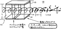
LagerwallおよびClarkは、表面安定化強誘電性液晶(以下、SSFLCと呼ぶ)の効果、そして電気光学シャッターおよび表示素子への応用について記載した(米国特許第4,367,924号および第4,563,059号)。SSFLCセル中で、FLCは、透明電極間で、いわゆる「ブックシェルフ(bookshelf)」配向状態にある。「ブックシェルフ」配向とは、スメクティック層が電極に対して実質的に垂直であり、FLC分子の長手方向軸が電極に平行である配向状態である。この配置では、強誘電相中で典型的に形成される自然のらせんが、セル内の表面相互作用により抑制される。らせんがこのように抑制される結果、双安定性セルが形成される。双安定性セルとは、印加された駆動電圧の符号を変更することにより、セルの光軸が電極の面内で2θ旋光し得るセルである。但し、θは傾き(tilt)角である。傾き角は、FLC固有の特性である。らせんを抑制するためには、セルの厚み(d)が、らせんピッチ長に相当するか、またはそれより小さくなければならない。したがって、セルの厚みが0.5〜6μmであることが最も有用である(複屈折は0.15〜0.3であると考える)可視光に応用する場合、FLCセルでのSSFLCの自然のらせんピッチは、0.5〜10μmよりも長いべきである。 Lagerwall and Clark described the effects of surface-stabilized ferroelectric liquid crystals (hereinafter referred to as SSFLC) and their application to electro-optic shutters and display elements (US Pat. Nos. 4,367,924 and 4,563). , 059). In an SSFLC cell, the FLC is in a so-called “bookshelf” orientation between transparent electrodes. A “bookshelf” orientation is an orientation in which the smectic layer is substantially perpendicular to the electrode and the longitudinal axis of the FLC molecule is parallel to the electrode. In this arrangement, the natural helix typically formed in the ferroelectric phase is suppressed by surface interactions within the cell. As a result of the suppression of the helix, a bistable cell is formed. A bistable cell is a cell in which the optical axis of the cell can rotate 2θ in the plane of the electrode by changing the sign of the applied drive voltage. Where θ is the tilt angle. The tilt angle is a characteristic unique to FLC. In order to suppress the helix, the cell thickness (d) must correspond to or be smaller than the helix pitch length. Therefore, it is most useful that the cell thickness is 0.5-6 μm (considering birefringence is 0.15-0.3), when applied to visible light, the natural nature of SSFLC in FLC cells. The helical pitch should be longer than 0.5-10 μm.
スメクティックC*相中のらせんが表面安定化により抑制されないFLCセルでの電気光学効果もまた、既に記載されている。例えば、OstovskiらのAdvances
in Liquid Crystal Research and Applications、Oxford/Budapest.(1980)の469頁、およびFunfschillingおよびSchadtのJ.Appl.Phys.66(8):3877頁−3882頁(1989)に記載のねじれらせん強誘電(DHF)効果は、スメクティックC*(または他のキラルな傾いたスメクティック強誘電)相中の自然のらせんピッチが十分に短く、すなわち、FLCセルの厚み(d)よりも短く、そのためらせんが抑制されない、電極板間に配向されたFLCに見られる。DHFLC電気光学素子は、電極板間に配向されたFLCを有する。最も典型的には、FLCは平面配向され、「ブックシェルフ」配置(geometry)にある。電極に電圧が印加されることにより、FLC層を通過して電界が発生する。表面安定化FLC素子とは異なり、配向されたキラルスメクティック相の自然のらせんは、DHF効果形素子の、配向されたFLC材料中に見られる。図1に示すように、らせんは、電極板に平行で、且つ、スメクティック層に垂直である。らせんピッチ長とは、らせんが完全に一回転する部分の、らせん軸に沿った距離であり、ピッチの符号(+または−)は、らせんがねじれる方向を示す。ピッチは、正または負の値であり得、「短い」ピッチとは、らせんが完全に一回転する部分の軸方向の長さが比較的短いということである。本明細書で用いる用語「ピッチ」は、ピッチ長を意味し、「ピッチの符号」または「ねじれ」という用語は、らせんのねじれの方向を示す。
The electro-optic effect in FLC cells where the helix in the smectic C * phase is not suppressed by surface stabilization has also been described. For example, Ostovski et al. Advanceds
in Liquid Crystal Research and Applications, Oxford / Budapest. (1980), page 469, and Funfschilling and Schadt, J. MoI. Appl. Phys. 66 (8): The torsional helical ferroelectric (DHF) effect described in pages 3877-3882 (1989) is sufficient for the natural helical pitch in the smectic C * (or other chiral tilted smectic ferroelectric) phase. Short, ie shorter than the thickness (d) of the FLC cell, so that the helix is not suppressed and is found in FLCs oriented between the electrode plates. The DHFLC electro-optic element has an FLC oriented between the electrode plates. Most typically, the FLC is planarly oriented and in a “bookshelf” geometry. When a voltage is applied to the electrodes, an electric field is generated through the FLC layer. Unlike surface-stabilized FLC devices, the natural helix of the oriented chiral smectic phase is found in the oriented FLC material of the DHF effect device. As shown in FIG. 1, the helix is parallel to the electrode plate and perpendicular to the smectic layer. The helical pitch length is the distance along the helical axis at the part where the spiral is completely rotated, and the sign (+ or −) of the pitch indicates the direction in which the spiral is twisted. The pitch can be positive or negative and “short” pitch means that the axial length of the portion of the spiral that makes a complete revolution is relatively short. As used herein, the term “pitch” refers to pitch length, and the term “pitch sign” or “twist” refers to the direction of helical twist.
SSFLCおよびDHFセルは、複数の電極板のうちのいずれかが反射性である、反射モードにおいて作用し得る(例えば、米国特許第4,799,776号を参照せよ)。 SSFLC and DHF cells can operate in a reflective mode where any of the plurality of electrode plates is reflective (see, eg, US Pat. No. 4,799,776).
C*らせんピッチ長が、可視光の波長に相当する時、素子中にストライプパターンが現れ、実際に回折格子が形成される。ピッチ長が光の波長よりも短い時(および好ましくは
、光の1/2λよりも短い時)、光の回折は最小であり、FLCの見かけの屈折率は、図1に示すようにらせんの多くの配向方向にわたって平均化されている。電界が発生せず、且つ、表面安定化もされていない、電界が存在しない(field−free)状態では、C*らせんは自然状態にある。分子の配向ベクトル(director)
When the C * helical pitch length corresponds to the wavelength of visible light, a stripe pattern appears in the element, and a diffraction grating is actually formed. When the pitch length is shorter than the wavelength of light (and preferably less than 1 / 2λ of light), the light diffraction is minimal and the apparent refractive index of the FLC is helical as shown in FIG. Averaged over many orientation directions. In a field-free state where no electric field is generated and the surface is not stabilized, the C * helix is in a natural state. Molecular orientation vector
FLC層を通過して印加された電圧が、ある臨界レベルECよりも高い場合、らせんは完全に解けて、SSFLC素子中でのように、2つの異なる光学状態を形成する。ECよりも低い電圧を印加すると、らせんが変形し、DHFLCの光軸が効果的に旋光する。DHFLC層の光軸の方向は、印加された電界に比例して連続的に変化し得、したがって、FLCの光学的異方性を変化させる。DHFセルは、印加された電界の大きさに依存する光軸旋光を示し、そして印加された電界の大きさに基づいて、見かけの複屈折(Δn)の変化もまた示す。 If the voltage applied through the FLC layer is higher than a certain critical level E C , the helix is completely unwound and forms two different optical states, as in an SSFLC element. When a voltage lower than E C is applied, the helix is deformed and the optical axis of the DHFLC is effectively rotated. The direction of the optical axis of the DHFLC layer can change continuously in proportion to the applied electric field, thus changing the optical anisotropy of the FLC. The DHF cell exhibits optical axis rotation that depends on the magnitude of the applied electric field, and also shows the change in apparent birefringence (Δn) based on the magnitude of the applied electric field.
DHFLCの光軸旋光の、電界誘導角の最高値は、材料の傾き角であるθである。+/−電圧ステップである+/−Emaxを印加することにより、光軸旋光の電界誘導角の最高値を2θにし得る。但し、Emaxは、θの旋光を得るために必要な最小電圧であり、Emaxの値はEcよりも小さい。 The maximum value of the electric field induction angle of the optical axis rotation of DHFLC is θ which is the tilt angle of the material. By applying +/− E max which is a +/− voltage step, the maximum value of the electric field induction angle of the optical axis rotation can be set to 2θ. However, E max is the minimum voltage required to obtain the optical rotation of θ, and the value of E max is smaller than E c .
DHF効果形セルは、典型的には、上記の平均化により、SSFLCセルよりも大幅に低い見かけの屈折率を示す。したがって、所望の光学的リタデーション(retardation)を得るために、DHFセルは、典型的には対応するSSFLCセルよりも厚い。DHFLCセルの複屈折は、典型的には約0.06〜0.13の範囲で変化し、SSFLCセルの約1/2である。その結果、DHFLCの波長板は、典型的には対応するSSFLCの波長板よりも厚い。セルの厚みを最小にするためには、高複屈折材料をDHFに用いることが有用である。 DHF effect cells typically exhibit an apparent refractive index that is significantly lower than SSFLC cells due to the averaging described above. Thus, to obtain the desired optical retardation, a DHF cell is typically thicker than the corresponding SSFLC cell. The birefringence of the DHFLC cell typically varies in the range of about 0.06 to 0.13 and is about ½ of the SSFLC cell. As a result, DHFLC waveplates are typically thicker than the corresponding SSFLC waveplates. In order to minimize the cell thickness, it is useful to use a high birefringence material for the DHF.
Ecは、FLCの自発分極および強誘電相のピッチに反比例し、以下の関係を有する。 E c is inversely proportional to the spontaneous polarization of the FLC and the pitch of the ferroelectric phase, and has the following relationship.
![]()
![]()
![]()
させることにより、応答速度が大幅に上昇し得、一方、閾値電圧を低く維持し得る。粘度を低下させることによってもまた、応答速度が上昇する。
![]()
欧州特許出願第309,774号は、電界の変化によりらせん構造が変化し、それによって光学的異方性が変化する、キラルスメクティックFLCを含むDHFLC表示素子に関する。上記出願はDHFセルに関し、FLCのらせんピッチに対するこの液晶セルの厚みの比(d/p)は5より大きく、好ましくは10より大きい。但し、θは22.5゜と50゜との間であり、且つ、いわゆる相関数 European Patent Application No. 309,774 relates to a DHFLC display element including a chiral smectic FLC in which the helical structure changes due to a change in electric field, thereby changing the optical anisotropy. The above application relates to a DHF cell, wherein the ratio of the thickness of the liquid crystal cell to the helical pitch of the FLC (d / p) is greater than 5, preferably greater than 10. However, θ is between 22.5 ° and 50 °, and the so-called correlation number
![]()
![]()
欧州特許出願第405,346号は、アキラルなスメクティックCホスト混合物と1μm未満のピッチを誘導するドーパントとを含む、配向されたFLCを有する、双安定性FLCセルに関する。上記混合物は、10nC/cm2より大きい自発分極および10゜より大きいθを有すると考えられる。上記セルは、電界中でうまく形成された後、電圧0の時、不均質な構造を示す直交偏光子の間に平行な暗線を表示する。 European patent application 405,346 relates to a bistable FLC cell having an oriented FLC comprising an achiral smectic C host mixture and a dopant that induces a pitch of less than 1 μm. The mixture is believed to have a spontaneous polarization greater than 10 nC / cm 2 and a θ greater than 10 °. The cell, after successfully forming in an electric field, displays parallel dark lines between orthogonal polarizers exhibiting a heterogeneous structure when the voltage is zero.
欧州特許出願第404,081号は、分極が大きく、且つ、ピッチが短いFLC素子に関する。上記出願は、短いC*ピッチを有する材料の使用に関する。但し、自発分極の大きいセルで見られる光学的ヒステリシスを排除するために、SSFLCセルでは、pは、せいぜい1/2d未満である。C*ピッチが0.25μmと0.63μmとの間である混合物は報告されているが、報告されている混合物のうち、室温で最も短かったピッチは、0.39μmであった。C*ピッチの短いFLC混合物は、少なくとも8μmより長いN*ピッチを有するということが報告されている。 European Patent Application No. 404,081 relates to FLC elements with large polarization and short pitch. The application relates to the use of materials with a short C * pitch. However, in order to eliminate the optical hysteresis seen in cells with a large spontaneous polarization, in SSFLC cells, p is at most less than 1 / 2d. Mixtures with a C * pitch between 0.25 and 0.63 μm have been reported, but the shortest pitch among the reported mixtures at room temperature was 0.39 μm. It has been reported that FLC mixtures with a short C * pitch have an N * pitch longer than at least 8 μm.
FunfschillingおよびSchadtのJ.Appl.Phys.66(8):3877頁−3882頁(1989)は、応答性が高く、且つ、複数化可能なDHFLC表示装置に関する。上記文献の著者は、DHFセルは、セルの厚みよりも大幅に短いピッチを有するFLC、および液晶セル内に弱い表面相互作用を必要とすると記載している。らせんが解けようとする傾向を減少させるためのセル調製方法が、以下のようにいくつか報告されている。すなわち、(1)剪断応力(shear)をかける、(2)上部セル板と下部セル板とを異なる方向でラビングする、および(3)SSFLCにジグザク欠陥をもたらす表面処理である。しかし、これらの処理は、セルの光学的コントラストに悪影響を与える。上記文献の著者は、配向された層を一方向にラビングして得られたDHFセルのコントラスト比(ON/OFF)は12:1であり、剪断応力をかけて得られたDHFセルのコントラスト比は40:1であると報告している。したがって、上記処理による、高コントラストDHFLC電気光学素子の製造には問題がある。 Funfschilling and Schadt, J.M. Appl. Phys. 66 (8): 3877-3882 (1989) relates to a DHFLC display device which has high responsiveness and can be made plural. The author of the above document states that DHF cells require FLC with a pitch much shorter than the cell thickness and weak surface interactions within the liquid crystal cell. Several cell preparation methods to reduce the tendency to unravel the helix have been reported: That is, (1) applying a shear stress, (2) rubbing the upper cell plate and the lower cell plate in different directions, and (3) a surface treatment that causes zigzag defects in the SSFLC. However, these treatments adversely affect the optical contrast of the cell. The author of the above-mentioned document shows that the contrast ratio (ON / OFF) of the DHF cell obtained by rubbing the oriented layer in one direction is 12: 1, and the contrast ratio of the DHF cell obtained by applying a shear stress. Reported 40: 1. Therefore, there is a problem in manufacturing a high contrast DHFLC electro-optic element by the above processing.
本発明は、このような事情を鑑みてなされたものであり、安定して解けないらせん配向ベクトル構造を維持するFLCを含む、高応答性、高コントラストFLC電気光学素子、特にこのようなDHFLC電気光学素子を提供することを目的とする。本発明の他の目的
は、短い強誘電相ピッチを必要とするFLC電気光学素子に有用な、特に、FLCにらせん配向ベクトル構造の存在を必要とするFLC電気光学素子に有用な液晶層特性、すなわち、短い強誘電相ピッチ、長いN*ピッチ、および大きな自発分極を有するFLC組成物を提供することにある。
The present invention has been made in view of such circumstances, and is a high-response, high-contrast FLC electro-optic element including an FLC that maintains a helical orientation vector structure that cannot be stably solved, particularly such a DHFLC electric device. An object is to provide an optical element. Another object of the present invention is to provide liquid crystal layer properties useful for FLC electro-optic elements that require a short ferroelectric phase pitch, and particularly useful for FLC electro-optic elements that require the presence of a helically-oriented vector structure in the FLC. That is, to provide an FLC composition having a short ferroelectric phase pitch, a long N * pitch, and a large spontaneous polarization.
本発明のさらに他の目的は、半波長板であり、特に、可視光波長領域で有用な半波長板であり、安定して解けないような、高応答性、高コントラストDHFLCセルを提供することにある。 Still another object of the present invention is a half-wave plate, particularly a half-wave plate useful in the visible light wavelength region, and to provide a high-response, high-contrast DHFLC cell that cannot be stably solved. It is in.
上記目的を達成するために、本発明は、らせん配向ベクトル(n*)構造を保持し、印加された電界または駆動電圧の大きさに基づいて光学的異方性が変化を示す非表面安定化FLCセルを含む、高コントラスト電気光学素子を提供する。特に、本発明は、高コントラストDHF効果型セルを提供する。 In order to achieve the above object, the present invention provides a non-surface stabilization that retains a helical orientation vector (n * ) structure and exhibits a change in optical anisotropy based on the magnitude of an applied electric field or driving voltage. A high contrast electro-optic element including an FLC cell is provided. In particular, the present invention provides a high contrast DHF effect cell.
本発明によれば、以下が提供される:
(1)少なくとも一方が透明または半透明である電極板間に設けられた、既知の厚みの強誘電性液晶層、
高コントラスト電気光学素子の光学的異方性が変化するように、該強誘電性液晶層を介して該電極板に電圧を印加する手段、および
電圧を印加した該素子の光学的異方性の変化状態を光学的に識別する手段、
を包含する、高コントラスト電気光学素子であって、
該層を有する強誘電性液晶が、強誘電相を示し、該強誘電相を示す温度よりも高い温度ではキラルネマティック相を示し、
該強誘電相では、該強誘電性液晶の自然のらせんピッチが、該素子の該強誘電性液晶層の厚みよりも十分短く、そのために、該強誘電性液晶が、らせん配向ベクトル構造を有し、かつ、表面安定化されておらず、
該ネマティック相では、該強誘電性液晶の自然のらせんピッチが、該強誘電性液晶層の厚みよりも十分長く、そのために、該素子の該強誘電性液晶層の配向が容易に行える、高コントラスト電気光学素子。
According to the present invention, the following is provided:
(1) A ferroelectric liquid crystal layer having a known thickness provided between electrode plates, at least one of which is transparent or translucent,
Means for applying a voltage to the electrode plate through the ferroelectric liquid crystal layer so that the optical anisotropy of the high-contrast electro-optical element changes, and the optical anisotropy of the element to which the voltage is applied Means for optically identifying the change state;
A high contrast electro-optic element comprising:
A ferroelectric liquid crystal having the layer exhibits a ferroelectric phase, and exhibits a chiral nematic phase at a temperature higher than the temperature at which the ferroelectric phase is exhibited;
In the ferroelectric phase, the natural helical pitch of the ferroelectric liquid crystal is sufficiently shorter than the thickness of the ferroelectric liquid crystal layer of the device, so that the ferroelectric liquid crystal has a helical orientation vector structure. And the surface is not stabilized,
In the nematic phase, the natural helical pitch of the ferroelectric liquid crystal is sufficiently longer than the thickness of the ferroelectric liquid crystal layer, so that the ferroelectric liquid crystal layer of the device can be easily aligned. Contrast electro-optic element.
(2)ねじれらせん強誘電性液晶(DHFLC)素子である、項目1に記載の高コントラスト電気光学素子。 (2) The high contrast electro-optic element according to item 1, which is a twisted spiral ferroelectric liquid crystal (DHFLC) element.
(3)上記強誘電相での自然のらせんピッチが、有用な素子動作温度では約1μm以下である、項目1に記載の高コントラスト電気光学素子。 (3) The high-contrast electro-optic element according to item 1, wherein the natural helical pitch in the ferroelectric phase is about 1 μm or less at a useful element operating temperature.
(4)上記ネマティック相での自然のらせんピッチが、約4μm以上である、項目3に記載の高コントラスト電気光学素子。 (4) The high-contrast electro-optical element according to item 3, wherein the natural helical pitch in the nematic phase is about 4 μm or more.
(5)上記強誘電性液晶層の厚みが約0.50と6.0μmとの間である、項目1に記載の高コントラスト電気光学素子。 (5) The high-contrast electro-optical element according to item 1, wherein the ferroelectric liquid crystal layer has a thickness between about 0.50 and 6.0 μm.
(6)上記強誘電相での自然のらせんピッチが、室温では0.39μm未満である、項目1に記載の高コントラスト電気光学素子。 (6) The high contrast electro-optic element according to item 1, wherein the natural helical pitch in the ferroelectric phase is less than 0.39 μm at room temperature.
(7)上記強誘電相での自然のらせんピッチが、室温では0.25μm未満である、項目1に記載の高コントラスト電気光学素子。 (7) The high-contrast electro-optic element according to item 1, wherein the natural helical pitch in the ferroelectric phase is less than 0.25 μm at room temperature.
(8)上記強誘電相での自然のらせんピッチが、室温では0.15μm未満である、項
目1に記載の高コントラスト電気光学素子。
(8) The high contrast electro-optical element according to item 1, wherein the natural helical pitch in the ferroelectric phase is less than 0.15 μm at room temperature.
(9)上記キラルネマティック相での自然のらせんピッチが、N*転移点よりも少なくとも約1℃から2℃高い温度では、上記強誘電性液晶(FLC)相の厚み以上である、項目1に記載の高コントラスト電気光学素子。 (9) Item 1 wherein the natural helical pitch in the chiral nematic phase is at least about 1 ° C. to 2 ° C. higher than the N * transition point and is equal to or greater than the thickness of the ferroelectric liquid crystal (FLC) phase. The high-contrast electro-optical element described.
(10)上記キラルネマティック相での自然のらせんピッチが、N*転移点よりも少なくとも約1℃から2℃高い温度では、上記強誘電性液晶(FLC)相の厚みの少なくとも約4倍である、項目9に記載の高コントラスト電気光学素子。
(10) The natural helical pitch in the chiral nematic phase is at least about 4 times the thickness of the ferroelectric liquid crystal (FLC) phase at a temperature at least about 1 ° C. to 2 ° C. higher than the N * transition point.
(11)上記強誘電相がスメクティックC*相である、項目1に記載の高コントラスト電気光学素子。 (11) The high contrast electro-optic element according to item 1, wherein the ferroelectric phase is a smectic C * phase.
(12)上記強誘電相での自然のらせんピッチが、可視光の波長の1/2未満である、項目1に記載の高コントラスト電気光学素子。 (12) The high-contrast electro-optical element according to item 1, wherein the natural helical pitch in the ferroelectric phase is less than half of the wavelength of visible light.
(13)上記強誘電性液晶層に接した上記強誘電性液晶層の配向手段をさらに包含し、それによって、該強誘電性液晶の分子の分子配向ベクトルが選択された方向に実質的に配向する、項目1に記載の高コントラスト電気光学素子。 (13) It further includes alignment means for the ferroelectric liquid crystal layer in contact with the ferroelectric liquid crystal layer, whereby the molecular alignment vector of the molecules of the ferroelectric liquid crystal is substantially aligned in the selected direction. The high-contrast electro-optical element according to item 1.
(14)上記配向手段が、一方向にラビングされた高分子配向層を包含する、項目1に記載の高コントラスト電気光学素子。 (14) The high-contrast electro-optical element according to item 1, wherein the alignment means includes a polymer alignment layer rubbed in one direction.
(15)上記配向手段が、一方向にラビングされたナイロン配向層を包含する、項目14に記載の高コントラスト電気光学素子。 (15) The high-contrast electro-optic element according to item 14, wherein the alignment means includes a nylon alignment layer rubbed in one direction.
(16)上記一方向にラビングされたナイロン配向層が、上記電極板の内表面では、上記強誘電性液晶(FLC)層に接して設けられており、かつ、互いに対向する該電極板上の該ナイロン配向層のラビング方向が互いに平行である、項目15に記載の高コントラスト電気光学素子。
(16) The nylon alignment layer rubbed in one direction is provided on the inner surface of the electrode plate in contact with the ferroelectric liquid crystal (FLC) layer, and on the electrode plates facing each other. Item 16. The high contrast electro-optic element according to
(17)40:1以上のコントラストを有する、項目1に記載の高コントラスト電気光学素子。 (17) The high-contrast electro-optical element according to item 1, having a contrast of 40: 1 or more.
(18)100:1以上のコントラストを有する、項目1に記載の高コントラスト電気光学素子。 (18) The high-contrast electro-optic element according to item 1, having a contrast of 100: 1 or more.
(19)可視光波長領域では、実質的に半波長板である、項目1に記載の高コントラスト電気光学素子。 (19) The high-contrast electro-optical element according to item 1, which is substantially a half-wave plate in the visible light wavelength region.
(20)上記強誘電性液晶の複屈折がΔnである時、上記強誘電性液晶層の厚みが約0.25/Δn(μm)と0.30/Δn(μm)との間である、項目1に記載の高コントラスト電気光学素子。
(20) When the birefringence of the ferroelectric liquid crystal is Δn, the thickness of the ferroelectric liquid crystal layer is between about 0.25 / Δn (μm) and 0.30 / Δn (μm).
(21)強誘電相、および該強誘電相を示す温度より高い温度ではキラルネマティック相を示す、少なくとも2つの成分を含む、強誘電性液晶組成物であって、
N*転移点より少なくとも約1℃から2℃高い温度で該キラルネマティック相での自然のらせんピッチが、ほぼ室温での該強誘電相での自然のらせんピッチよりも少なくとも約4倍長い、強誘電性液晶組成物。
(21) A ferroelectric liquid crystal composition comprising a ferroelectric phase and at least two components exhibiting a chiral nematic phase at a temperature higher than the temperature exhibiting the ferroelectric phase,
A strong, natural helical pitch in the chiral nematic phase at least about 1 ° C. to 2 ° C. above the N * transition point is at least about 4 times longer than the natural helical pitch in the ferroelectric phase at about room temperature. Dielectric liquid crystal composition.
(22)キラルドーパントおよびホスト化合物を含む、項目21に記載の強誘電性液晶組成物。 (22) The ferroelectric liquid crystal composition according to item 21, comprising a chiral dopant and a host compound.
(23)上記ホスト化合物が、スメクティックCホストまたはスメクティックC*ホストである、項目22に記載の強誘電性液晶組成物。 (23) The ferroelectric liquid crystal composition according to item 22, wherein the host compound is a smectic C host or a smectic C * host.
(24)温度が低下するにつれて、上記相が、I→N*→スメクティック直交→スメクティック強誘電と転移する、項目22に記載の強誘電性液晶組成物。 (24) The ferroelectric liquid crystal composition according to item 22, wherein the phase transitions from I → N * → smectic orthogonal → smectic ferroelectric as the temperature decreases.
(25)温度が低下するにつれて、上記相が、I→N*→A→C*と転移する、項目24に記載の強誘電性液晶組成物。 (25) The ferroelectric liquid crystal composition according to item 24, wherein the phase transitions from I → N * → A → C * as the temperature decreases.
(26)上記キラルネマティック相での自然のらせんピッチが、上記強誘電相での自然のらせんピッチより少なくとも約10倍長い、項目21に記載の強誘電性液晶組成物。 (26) The ferroelectric liquid crystal composition according to item 21, wherein the natural helical pitch in the chiral nematic phase is at least about 10 times longer than the natural helical pitch in the ferroelectric phase.
(27)上記強誘電相がスメクティックC*相である、項目21に記載の強誘電性液晶組成物。 (27) The ferroelectric liquid crystal composition according to item 21, wherein the ferroelectric phase is a smectic C * phase.
(28)上記強誘電相では上記キラルドーパントと同一のピッチ符号を示し、かつ、上記キラルネマティック相では該キラルドーパントと逆のピッチ符号を示す、ネマティック相ピッチ補償剤をさらに含む、項目21に記載の強誘電性液晶組成物。 (28) Item 21 further includes a nematic phase pitch compensator that exhibits the same pitch sign as the chiral dopant in the ferroelectric phase and that exhibits a pitch sign opposite to that of the chiral dopant in the chiral nematic phase. Ferroelectric liquid crystal composition.
(29)上記強誘電相での自然のらせんピッチが、室温では0.25μm以下であり、上記キラルネマティック相での自然のらせんピッチが、N*転移点より少なくとも約1℃から2℃高い温度では8μm以上である、項目21に記載の強誘電性液晶組成物。 (29) The natural helical pitch in the ferroelectric phase is 0.25 μm or less at room temperature, and the natural helical pitch in the chiral nematic phase is at least about 1 ° C. to 2 ° C. higher than the N * transition point. The ferroelectric liquid crystal composition according to item 21, wherein the ferroelectric liquid crystal composition is 8 μm or more.
(30)約30重量%以下の上記キラルドーパントを含む、項目22に記載の強誘電性液晶材料。 (30) The ferroelectric liquid crystal material according to item 22, comprising about 30% by weight or less of the chiral dopant.
(31)上記キラルドーパントが、式R−A−Z1−B−O−Mで表されるラセミ化していない材料であって、
AおよびBが、各々独立して1,4−フェニレン、環状炭素原子のうちの1個または2個が窒素原子で置換される1,4−フェニレン、または1,4−シクロヘキシレンから選択され、Z1が、一重結合、酸素原子、−CO−O−基または−O−CO−基であり、Rが、1個以上の隣接しない炭素原子が二重結合、酸素原子、イオウ原子またはSi(CH3)2基で置換され得る1個から20個の炭素原子を有する基であり、そしてO−Mが、式
* *
O−CH2−CHX−CHY−CH2−R’
で表される2,3−ジハロアルキル部分であり、
*が不斉炭素であり、XおよびYが、各々独立してハロゲンであり、R’が、1個以上の隣接しない炭素原子が二重結合、酸素原子、イオウ原子、またはSi(CH3)2基で置換され得る1個から約20個の炭素原子を有する基あるいは−OCO−R’’で表されるアシル基であり、ここでR’’が、1個以上の隣接しない炭素原子が二重結合、酸素原子、イオウ原子またはSi(CH3)2基で置換され得る1個から20個の炭素原子を有する基である、項目22に記載の強誘電性液晶材料。
(31) The chiral dopant is a material that is not racemized formula R-A-Z 1 -B- O-M,
A and B are each independently selected from 1,4-phenylene, 1,4-phenylene in which one or two of the cyclic carbon atoms are replaced by nitrogen atoms, or 1,4-cyclohexylene; Z 1 is a single bond, oxygen atom, —CO—O— group or —O—CO— group, and R is one or more non-adjacent carbon atoms being a double bond, oxygen atom, sulfur atom or Si ( CH 3 ) groups having from 1 to 20 carbon atoms that can be substituted with 2 groups, and OM is represented by the formula
* *
O—CH 2 —CHX—CHY—CH 2 —R ′
A 2,3-dihaloalkyl moiety represented by:
* Is an asymmetric carbon, X and Y are each independently halogen, and R ′ is one or more non-adjacent carbon atoms are double bonds, oxygen atoms, sulfur atoms, or Si (CH 3 ). A group having from 1 to about 20 carbon atoms which can be substituted by 2 groups or an acyl group represented by -OCO-R ", wherein R" is one or more non-adjacent carbon atoms Item 23. The ferroelectric liquid crystal material according to Item 22, which is a group having 1 to 20 carbon atoms that can be substituted with a double bond, an oxygen atom, a sulfur atom, or a Si (CH 3 ) 2 group.
(32)上記キラルドーパントが、式
* *
R−A−B−O−CH2−CHF−CHF−CH2−R’
で表されるラセミ化していないキラルな2,3−ジフルオロアルキルオキシ化合物であって、
*が不斉炭素を表し、AまたはBのいずれか一方が1,4−フェニレンであり、AまたはBの他方が2,5−ピリミジンであり、R’が、1個から20個の炭素原子を有するアルキル基、または1個から20個の炭素原子を有する
−OCO−R’’で表されるアシル基である、項目31に記載の強誘電性液晶材料。
(32) The chiral dopant has the formula
* *
R—A—B—O—CH 2 —CHF—CHF—CH 2 —R ′
A non-racemicized chiral 2,3-difluoroalkyloxy compound represented by:
* Represents an asymmetric carbon, either A or B is 1,4-phenylene, the other of A or B is 2,5-pyrimidine, and R ′ is 1 to 20 carbon atoms. Item 32. The ferroelectric liquid crystal material according to Item 31, which is an alkyl group having an acyl group or an acyl group represented by —OCO—R ″ having 1 to 20 carbon atoms.
(33)上記ドーパントの立体構造が、2−R、3−Rまたは2−S、3−Sである、項目32に記載の強誘電性液晶材料。 (33) The ferroelectric liquid crystal material according to item 32, wherein the three-dimensional structure of the dopant is 2-R, 3-R or 2-S, 3-S.
(34)R’が、1個から20個の炭素原子を有するアルキル基である、項目32に記載の強誘電性液晶組成物。 (34) The ferroelectric liquid crystal composition according to item 32, wherein R ′ is an alkyl group having 1 to 20 carbon atoms.
(35)R’が、1個から20個の炭素原子を有するアシル基である、項目32に記載の強誘電性液晶組成物。 (35) The ferroelectric liquid crystal composition according to item 32, wherein R ′ is an acyl group having 1 to 20 carbon atoms.
(36)式R1−O−C−D−O−R2で表される1個以上の化合物を少なくとも約10重量%含む、ホスト材料を含む強誘電性液晶組成物であって、
CまたはDのいずれか一方が1,4−フェニレンであり、CまたはDの他方が、環状炭素原子のうちの1個以上が窒素原子で置換される1,4−フェニレンであり、R1およびR2が、各々独立して1個から20個の炭素原子を有するアルキル基またはアルケニル基、あるいは4個から22個の炭素原子を有するアルキルシリル基である、項目22に記載の強誘電性液晶組成物。
(36) A ferroelectric liquid crystal composition comprising a host material and comprising at least about 10% by weight of one or more compounds represented by the formula R 1 —O—C—D—O—R 2 ,
One of C or D is 1,4-phenylene, the other of C or D is 1,4-phenylene in which one or more of the cyclic carbon atoms is replaced by a nitrogen atom, and R 1 and Item 23. The ferroelectric liquid crystal according to item 22, wherein R 2 is each independently an alkyl or alkenyl group having 1 to 20 carbon atoms, or an alkylsilyl group having 4 to 22 carbon atoms. Composition.
(37)R1およびR2が、各々独立して1個から20個の炭素原子を有するアルキル基またはアルケニル基である、項目36に記載の強誘電性液晶組成物。 (37) The ferroelectric liquid crystal composition according to item 36, wherein R 1 and R 2 are each independently an alkyl group or an alkenyl group having 1 to 20 carbon atoms.
(38)ネマティック相ピッチ補償剤(compensation agent)をさらに含む、項目22に記載の強誘電性液晶化合物。 (38) The ferroelectric liquid crystal compound according to item 22, further comprising a nematic phase pitch compensator (compensation agent).
(39)さらに、式R3−E−F−Z2−R4で表される1個以上の化合物を含む強誘電性液晶組成物であって、
R3およびR4が、各々独立して1個から約20個の炭素原子を有するアルキル基またはアルケニル基、あるいは約4個から約22個の炭素原子を有するアルキルシリル基であり、EまたはFのいずれか一方が、1,4−フェニレンであり、EまたはFの他方が、環状炭素原子のうちの1個または2個が窒素原子で置換される1,4−フェニレンであり、Z2が、酸素原子、−CO−O−基または−O−CO−基である、項目22に記載の強誘電性液晶組成物。
(39) A ferroelectric liquid crystal composition further comprising one or more compounds represented by the formula R 3 —E—F—Z 2 —R 4 ,
R 3 and R 4 are each independently an alkyl or alkenyl group having 1 to about 20 carbon atoms, or an alkylsilyl group having about 4 to about 22 carbon atoms, and E or F Is one of 1,4-phenylene, the other of E or F is 1,4-phenylene in which one or two of the cyclic carbon atoms are substituted with nitrogen atoms, and Z 2 is Item 23. The ferroelectric liquid crystal composition according to Item 22, which is an oxygen atom, a —CO—O— group or a —O—CO— group.
(40)Z2が酸素原子または−CO−O−基である、項目39に記載の強誘電性液晶組成物。 (40) The ferroelectric liquid crystal composition according to item 39, wherein Z 2 is an oxygen atom or a —CO—O— group.
(41)Z2が酸素原子である、項目39に記載の強誘電性液晶組成物。 (41) The ferroelectric liquid crystal composition according to item 39, wherein Z 2 is an oxygen atom.
(42)EまたはFのいずれか一方が1,4−フェニレンであり、EまたはFの他方が2,5−ピリミジンである、項目39に記載の強誘電性液晶組成物。 (42) The ferroelectric liquid crystal composition according to item 39, wherein either E or F is 1,4-phenylene, and the other of E or F is 2,5-pyrimidine.
(43)R3およびR4が、各々独立して1個から20個の炭素原子を有するアルキル基またはアルケニル基である、項目39に記載の強誘電性液晶組成物。 (43) The ferroelectric liquid crystal composition according to item 39, wherein R 3 and R 4 are each independently an alkyl group or an alkenyl group having 1 to 20 carbon atoms.
(44)さらに、式R5−G−H−Z3−Cyc−R6で表される1個以上の化合物を含む強誘電性液晶組成物であって、
R5およびR6が、各々独立して1個から20個の炭素原子を有するアルキル基またはアルケニル基、あるいは約4個から約22個の炭素原子を有するアルキルシリル基であり、EまたはFのいずれか一方が1,4−フェニレンであり、EまたはFの他方が、環状炭素原子の1個または2個が窒素原子で置換される1,4−フェニレンであり、Z3が、一重結合、酸素原子、−O−CO−基または−CO−O−基であり、Cycが1,4−シクロヘキシレン基である、項目22に記載の強誘電性液晶組成物。
(44) A ferroelectric liquid crystal composition further comprising one or more compounds represented by the formula R 5 —G—H—Z 3 —Cyc—R 6 ,
R 5 and R 6 are each independently an alkyl or alkenyl group having 1 to 20 carbon atoms, or an alkylsilyl group having about 4 to about 22 carbon atoms, Either one is 1,4-phenylene, the other of E or F is 1,4-phenylene in which one or two cyclic carbon atoms are substituted with nitrogen atoms, and Z 3 is a single bond, Item 23. The ferroelectric liquid crystal composition according to item 22, which is an oxygen atom, —O—CO— group or —CO—O— group, and Cyc is a 1,4-cyclohexylene group.
(45)Z3が、一重結合または−O−CO−基である、項目44に記載の強誘電性液晶組成物。 (45) The ferroelectric liquid crystal composition according to item 44, wherein Z 3 is a single bond or an —O—CO— group.
(46)Z3が−O−CO−基である、項目45に記載の強誘電性液晶組成物。
(46) The ferroelectric liquid crystal composition according to
(47)Cycがトランス−1,4−シクロヘキシレン基である、項目44に記載の強誘電性液晶組成物。 (47) The ferroelectric liquid crystal composition according to item 44, wherein Cyc is a trans-1,4-cyclohexylene group.
(48)GまたはHのいずれか一方が1,4−フェニレンであり、GまたはHの他方が2,5−ピリミジンである、項目44に記載の強誘電性液晶組成物。 (48) The ferroelectric liquid crystal composition according to item 44, wherein either G or H is 1,4-phenylene, and the other of G or H is 2,5-pyrimidine.
(49)R5およびR6が、各々独立して1個から約20個の炭素原子を有するアルキル基またはアルケニル基である、項目44に記載の強誘電性液晶組成物。 (49) A ferroelectric liquid crystal composition according to item 44, wherein R 5 and R 6 are each independently an alkyl group or an alkenyl group having 1 to about 20 carbon atoms.
(50)30重量%以下の上記キラルドーパント、50重量%以上の上記ホスト化合物、および1重量%以下の上記ピッチ補償剤を含む、項目22に記載の強誘電性液晶組成物。 (50) The ferroelectric liquid crystal composition according to item 22, comprising 30% by weight or less of the chiral dopant, 50% by weight or more of the host compound, and 1% by weight or less of the pitch compensator.
(51)傾き角が約18゜より大きく、自発分極が約10nC/cm2より大きい、項目21に記載の強誘電性液晶組成物。 (51) The ferroelectric liquid crystal composition according to item 21, wherein the tilt angle is larger than about 18 ° and the spontaneous polarization is larger than about 10 nC / cm 2 .
本発明の高コントラスト電気光学素子は、少なくとも一方が透明または半透明である電極板間に設けられた既知の厚みの強誘電性液晶層、高コントラスト電気光学素子の光学的異方性が変化するように、強誘電性液晶層を介して電極板に電圧を印加する手段、および電圧を印加した素子の光学的異方性の変化状態を光学的に識別する手段を包含する。ここで、層を有する強誘電性液晶は、強誘電相を示し、強誘電相を示す温度よりも高い温度ではキラルネマティック相を示す。強誘電相では、強誘電性液晶の自然のらせんピッチは、素子の強誘電性液晶層の厚みよりも十分短く、そのために、強誘電性液晶は、らせん配向ベクトル構造を有し、かつ、表面安定化されていない。ネマティック相では、強誘電性液晶の自然のらせんピッチは、強誘電性液晶層の厚みよりも十分長く、そのために、素子の強誘電性液晶層の配向が容易に行える。 The high-contrast electro-optical element of the present invention changes the optical anisotropy of a ferroelectric liquid crystal layer having a known thickness provided between electrode plates, at least one of which is transparent or translucent, Thus, a means for applying a voltage to the electrode plate through the ferroelectric liquid crystal layer and a means for optically identifying the change state of the optical anisotropy of the element to which the voltage is applied are included. Here, the ferroelectric liquid crystal having a layer exhibits a ferroelectric phase, and exhibits a chiral nematic phase at a temperature higher than the temperature at which the ferroelectric phase is exhibited. In the ferroelectric phase, the natural helical pitch of the ferroelectric liquid crystal is sufficiently shorter than the thickness of the ferroelectric liquid crystal layer of the device, so that the ferroelectric liquid crystal has a helical orientation vector structure and has a surface Not stabilized. In the nematic phase, the natural helical pitch of the ferroelectric liquid crystal is sufficiently longer than the thickness of the ferroelectric liquid crystal layer, so that the ferroelectric liquid crystal layer of the device can be easily aligned.
好適な実施態様では、本発明の高コントラスト電気光学素子は、ねじれらせん強誘電性液晶(DHFLC)素子である。 In a preferred embodiment, the high contrast electro-optic element of the present invention is a twisted helical ferroelectric liquid crystal (DHFLC) element.
好適な実施態様では、上記強誘電相での自然のらせんピッチは、有用な素子動作温度では約1μm以下であり、上記ネマティック相での自然のらせんピッチは、約4μm以上である。上記強誘電相での自然のらせんピッチは、好ましくは、室温では0.39μm未満であり、より好ましくは、0.25μm未満であり、さらにより好ましくは、0.15μm未満である。上記キラルネマティック相での自然のらせんピッチは、好ましくは、N*
転移点よりも少なくとも約1℃から2℃高い温度では、上記強誘電性液晶(FLC)相の厚み以上であり、より好ましくは、強誘電性液晶相の厚みの少なくとも約4倍である。好適な実施態様では、上記強誘電相での自然のらせんピッチは、可視光の波長の1/2未満である。
In a preferred embodiment, the natural helical pitch in the ferroelectric phase is about 1 μm or less at useful device operating temperatures, and the natural helical pitch in the nematic phase is about 4 μm or more. The natural helical pitch in the ferroelectric phase is preferably less than 0.39 μm at room temperature, more preferably less than 0.25 μm, and even more preferably less than 0.15 μm. The natural helical pitch in the chiral nematic phase is preferably N *
At a temperature at least about 1 ° C. to 2 ° C. higher than the transition point, the thickness is equal to or greater than the thickness of the ferroelectric liquid crystal (FLC) phase, and more preferably at least about 4 times the thickness of the ferroelectric liquid crystal phase. In a preferred embodiment, the natural helical pitch in the ferroelectric phase is less than half the wavelength of visible light.
好適な実施態様では、本発明の高コントラスト電気光学素子は、上記強誘電性液晶層に接した上記強誘電性液晶層の配向手段をさらに包含し、それによって、強誘電性液晶の分子の分子配向ベクトルは選択された方向に実質的に配向する。上記配向手段は、好ましくは、一方向にラビングされた高分子配向層を包含し、より好ましくは、一方向にラビングされたナイロン配向層を包含する。上記一方向にラビングされたナイロン配向層は、好ましくは、上記電極板の内表面では強誘電性液晶層に接して設けられており、かつ、互いに対向する電極板上のナイロン配向層のラビング方向は互いに平行である。 In a preferred embodiment, the high-contrast electro-optic element of the present invention further includes alignment means for the ferroelectric liquid crystal layer in contact with the ferroelectric liquid crystal layer, whereby molecules of the ferroelectric liquid crystal molecules are included. The orientation vector is substantially oriented in the selected direction. The alignment means preferably includes a polymer alignment layer rubbed in one direction, and more preferably includes a nylon alignment layer rubbed in one direction. The nylon alignment layer rubbed in one direction is preferably provided in contact with the ferroelectric liquid crystal layer on the inner surface of the electrode plate, and the rubbing direction of the nylon alignment layer on the electrode plates facing each other. Are parallel to each other.
好適な実施態様では、本発明の高コントラスト電気光学素子は、可視光波長領域では実質的に半波長板である。 In a preferred embodiment, the high-contrast electro-optic element of the present invention is a substantially half-wave plate in the visible light wavelength region.
好適な実施態様では、上記強誘電性液晶の複屈折がΔnである時、上記強誘電性液晶層の厚みは約0.25/Δn(μm)と0.30/Δn(μm)との間である。 In a preferred embodiment, when the birefringence of the ferroelectric liquid crystal is Δn, the thickness of the ferroelectric liquid crystal layer is between about 0.25 / Δn (μm) and 0.30 / Δn (μm). It is.
本発明の強誘電性液晶組成物は、強誘電相、および強誘電相を示す温度より高い温度ではキラルネマティック相を示す、少なくとも2つの成分を含む。ここで、N*転移点より少なくとも約1℃から2℃高い温度で上記キラルネマティック相での自然のらせんピッチは、ほぼ室温での強誘電相での自然のらせんピッチよりも少なくとも約4倍長い。 The ferroelectric liquid crystal composition of the present invention includes a ferroelectric phase and at least two components that exhibit a chiral nematic phase at a temperature higher than the temperature that exhibits the ferroelectric phase. Here, the natural helical pitch in the chiral nematic phase at least about 1 ° C. to 2 ° C. above the N * transition point is at least about 4 times longer than the natural helical pitch in the ferroelectric phase at about room temperature. .
好適な実施態様では、本発明の強誘電性液晶組成物は、キラルドーパントおよびホスト化合物を含む。上記ホスト化合物は、好ましくは、スメクティックCホストまたはスメクティックC*ホストである。 In a preferred embodiment, the ferroelectric liquid crystal composition of the present invention includes a chiral dopant and a host compound. The host compound is preferably a smectic C host or a smectic C * host.
好適な実施態様では、温度が低下するにつれて、上記相は、I→N*→直交スメクティック→スメクティック強誘電と転移し、より好ましくは、I→N*→A→C*と転移する。 In a preferred embodiment, as the temperature decreases, the phase transitions from I → N * → orthogonal smectic → smectic ferroelectric, more preferably I → N * → A → C * .
好適な実施態様では、上記キラルネマティック相での自然のらせんピッチは、上記強誘電相での自然のらせんピッチより少なくとも約10倍長い。 In a preferred embodiment, the natural helical pitch in the chiral nematic phase is at least about 10 times longer than the natural helical pitch in the ferroelectric phase.
好適な実施態様では、本発明の強誘電性液晶組成物は、上記強誘電相では上記キラルドーパントと同一のピッチ符号を示し、かつ、キラルネマティック相ではキラルドーパントと逆のピッチ符号を示す、ネマティック相ピッチ補償剤をさらに含む。 In a preferred embodiment, the ferroelectric liquid crystal composition of the present invention has a nematic liquid crystal composition exhibiting the same pitch sign as the chiral dopant in the ferroelectric phase and the opposite pitch sign as the chiral dopant in the chiral nematic phase. A phase pitch compensator is further included.
好適な実施態様では、上記強誘電相での自然のらせんピッチは、室温では0.25μm以下であり、上記キラルネマティック相での自然のらせんピッチは、N*転移点より少なくとも約1℃から2℃高い温度では8μm以上である。 In a preferred embodiment, the natural helical pitch in the ferroelectric phase is 0.25 μm or less at room temperature, and the natural helical pitch in the chiral nematic phase is at least about 1 ° C. to 2 ° C. from the N * transition point. It is 8 μm or more at a high temperature.
好適な実施態様では、本発明の強誘電性液晶物質は約30重量%以下のキラルドーパントを含む。好適な実施態様では、本発明の強誘電性液晶材料のキラルドーパントは、式R−A−Z1−B−O−Mで表されるラセミ化していない化合物である。ここで、AおよびBは、各々独立して1,4−フェニレン、環状炭素原子のうちの1個または2個が窒素原子で置換される1,4−フェニレン、または1,4−シクロヘキシレンから選択され、Z1は、一重結合、酸素原子、−CO−O−基または−O−CO−基であり、Rは、1個以上の隣接しない炭素原子が二重結合、酸素原子、イオウ原子またはSi(CH3)2基で
置換され得る1個から20個の炭素原子を有する基である。そしてO−Mは、式
* *
O−CH2−CHX−CHY−CH2−R’
で表される2,3−ジハロアルキル部分であり、*は不斉炭素を表し、XおよびYは、各々独立してハロゲンであり、R’は、1個以上の隣接しない炭素原子が二重結合、酸素原子、イオウ原子、またはSi(CH3)2基で置換され得る1個から約20個の炭素原子を有する基あるいは−OCO−R’’で表されるアシル基であり、ここでR’’は、1個以上の隣接しない炭素原子が二重結合、酸素原子、イオウ原子またはSi(CH3)2基で置換され得る1個から20個の炭素原子を有する基である。上記キラルドーパントは、好ましくは、式
* *
R−A−B−O−CH2−CHF−CHF−CH2−R’
で表されるラセミ化していないキラルな2,3−ジフルオロアルキルオキシである。ここで、*は不斉炭素を表し、AまたはBのいずれか一方は1,4−フェニレンであり、AまたはBの他方は2,5−ピリミジンであり、R’は、1個から20個の炭素原子を有するアルキル基、または1個から20個の炭素原子を有する−OCO−R’’で表されるアシル基である。より好ましくは、上記ドーパントの立体構造は、2−R、3−Rまたは2−S、3−Sである。好ましくは、 R’は、1個から20個の炭素原子を有するアルキル基であり、または、1個から20個の炭素原子を有するアシル基である。
In a preferred embodiment, the ferroelectric liquid crystal material of the present invention comprises no more than about 30% by weight chiral dopant. In a preferred embodiment, the chiral dopant of the ferroelectric liquid crystal material of the present invention is a non-racemicized compound represented by the formula R—A—Z 1 —B—O—M. Here, A and B are each independently 1,4-phenylene, 1,4-phenylene in which one or two of the cyclic carbon atoms are substituted with nitrogen atoms, or 1,4-cyclohexylene. Z 1 is a single bond, oxygen atom, —CO—O— group or —O—CO— group, and R is one or more non-adjacent carbon atoms are double bonds, oxygen atoms, sulfur atoms Or a group having 1 to 20 carbon atoms that can be substituted with two Si (CH 3 ) groups. And OM is the formula
* *
O—CH 2 —CHX—CHY—CH 2 —R ′
, * Represents an asymmetric carbon, X and Y are each independently halogen, and R ′ is a double bond of one or more non-adjacent carbon atoms. A group having 1 to about 20 carbon atoms which can be substituted by a bond, oxygen atom, sulfur atom, or Si (CH 3 ) 2 group, or an acyl group represented by —OCO—R ″, R ″ is a group having 1 to 20 carbon atoms in which one or more non-adjacent carbon atoms can be substituted with a double bond, oxygen atom, sulfur atom or Si (CH 3 ) 2 group. The chiral dopant preferably has the formula
* *
R—A—B—O—CH 2 —CHF—CHF—CH 2 —R ′
It is a chiral 2,3-difluoroalkyloxy which is not racemized. Here, * represents an asymmetric carbon, one of A or B is 1,4-phenylene, the other of A or B is 2,5-pyrimidine, and R ′ is 1 to 20 Or an acyl group represented by —OCO—R ″ having 1 to 20 carbon atoms. More preferably, the steric structure of the dopant is 2-R, 3-R or 2-S, 3-S. Preferably, R ′ is an alkyl group having 1 to 20 carbon atoms or an acyl group having 1 to 20 carbon atoms.
好適な実施態様では、本発明の強誘電性液晶材料は、30重量%以下の上記キラルドーパント、50重量%以上の上記ホスト化合物、および1重量%以下の上記ピッチ補償剤を含む。 In a preferred embodiment, the ferroelectric liquid crystal material of the present invention comprises 30% by weight or less of the chiral dopant, 50% by weight or more of the host compound, and 1% by weight or less of the pitch compensator.
本発明のFLCセルは、強誘電相、例えば、スメクティックC*相を示し、強誘電相を示す温度より高い温度ではキラルネマティック(N*)相を示す、キラルな強誘電性液晶を含む。本発明のFLCセルは、均一な間隔をあけて設けられた、電極を含む板を含み、上記電極板間にFLCが配向されている。上記電極板のうち、少なくとも一方が、透明または半透明である。電極板のうちの一方は、反射性であり得、それにより、反射モードで動作するDHFセルを製造し得る。上記セルは、電界の印加により誘導される、FLCの光学的異方性の変化を検出する手段を備える。例えば、透過モードセルでは、入射光偏光子および偏光検光子が、電極板のいずれか一方の側に設けられ得る。 The FLC cell of the present invention includes a chiral ferroelectric liquid crystal that exhibits a ferroelectric phase, eg, a smectic C * phase, and exhibits a chiral nematic (N * ) phase at temperatures above the ferroelectric phase. The FLC cell of the present invention includes plates including electrodes that are provided at uniform intervals, and the FLC is oriented between the electrode plates. At least one of the electrode plates is transparent or translucent. One of the electrode plates can be reflective, thereby producing a DHF cell operating in reflective mode. The cell comprises means for detecting changes in FLC optical anisotropy induced by the application of an electric field. For example, in a transmission mode cell, an incident light polarizer and a polarization analyzer can be provided on either side of the electrode plate.
FLCを配向する手段が、セル内、例えば、電極板の内表面でFLCに接して設けられ得る。上記配向手段は、板の間にFLCを挿入する前に、一方向の、平行または逆平行のラビングまたはブラッシングが施された配向層であり得る。例えば、ナイロン、ポリイミドまたはポリアミド層が、電極板に蒸着またはスピンコートされ得る。SiOセルの射方蒸着は、別の配向手段である。高コントラストDHFLCセルの製造のためには、ラビングされたナイロンの配向層が好ましい。 Means for orienting the FLC can be provided in contact with the FLC in the cell, eg, on the inner surface of the electrode plate. The orientation means may be an orientation layer that has been unidirectionally parallel or antiparallel rubbed or brushed prior to inserting the FLC between the plates. For example, a nylon, polyimide or polyamide layer can be deposited or spin coated on the electrode plate. Radial deposition of SiO cells is another orientation means. For the production of high contrast DHFLC cells, a rubbed nylon alignment layer is preferred.
本発明の素子のFLC層は、好ましくは、平面配向され、最も好ましくは、「ブックシェルフ」配置に配向される。本発明のFLC素子では、強誘電相中のFLCの自然のらせんピッチは、強誘電性液晶相の厚み、すなわちFLC層の厚み(d)よりも十分短い。すなわち、上記らせんピッチは、上記素子中の強誘電性液晶層が、らせん配向ベクトル構造を示し、したがって表面安定化しないように、十分短い。FLCのN*相では、自然のらせんピッチは、上記素子のFLCの配向が容易に行えるように、セルの厚みよりも十分長い。それにより、上記素子は、少なくとも40:1、より好ましくは100:1以上の高い光学的コントラストを示す。さらに良好な配向を得るためには、FLCがまた、強誘電相とN*相との間の温度で、直交スメクティック相中間体をも有することが望ましい。直交スメクティック相は、他の相の中で、スメクティックA相およびスメクティックB相を
含む。スメクティックA相の存在が好ましい。
The FLC layer of the device of the present invention is preferably planarly oriented, and most preferably oriented in a “bookshelf” arrangement. In the FLC element of the present invention, the natural helical pitch of FLC in the ferroelectric phase is sufficiently shorter than the thickness of the ferroelectric liquid crystal phase, that is, the thickness (d) of the FLC layer. That is, the helical pitch is sufficiently short so that the ferroelectric liquid crystal layer in the device exhibits a helical orientation vector structure and therefore does not surface stabilize. The FLC of N * phase, the natural helical pitch, such that the orientation of the FLC of the device can be performed easily, sufficiently longer than the thickness of the cell. Thereby, the element exhibits a high optical contrast of at least 40: 1, more preferably 100: 1 or more. In order to obtain better alignment, it is also desirable that the FLC also have an orthogonal smectic phase intermediate at a temperature between the ferroelectric phase and the N * phase. The orthogonal smectic phase includes, among other phases, a smectic A phase and a smectic B phase. The presence of a smectic A phase is preferred.
本発明の高コントラスト電気光学素子は、好ましくはFLC材料を含み、ここで、強誘電相中の自然のらせんピッチ長は、約1/5d(d=FLCセルの厚み)未満であり、N*相中の自然のらせんピッチ長は、少なくとも実質的にdに等しい。強誘電相中の自然のピッチ長が、約1/10d未満であることが、より望ましい。N*相中の自然のらせんピッチは、好ましくは、約4dよりも長く、より好ましくは、約8dよりも長い。 The high-contrast electro-optic element of the present invention preferably comprises an FLC material, where the natural helical pitch length in the ferroelectric phase is less than about 1 / 5d (d = FLC cell thickness) and N * The natural helical pitch length in the phase is at least substantially equal to d. More desirably, the natural pitch length in the ferroelectric phase is less than about 1 / 10d. The natural helical pitch in the N * phase is preferably greater than about 4d, more preferably greater than about 8d.
本発明のFLCは、有用な素子動作温度で、所望のピッチ特性を有する強誘電相を示すことが好ましい。FLCまたはDHFLC素子にとって有用な動作温度は、上記素子の所望の応用分野に依存する。いくつかの場合は、室温(20℃〜30℃)またはそれより低い温度(10℃〜30℃)での動作が望ましい。別の場合、例えば、投影型素子では、より高い動作温度(50℃〜80℃)が望ましい。したがって、本発明の素子の有用な動作温度は、約10℃から約80℃の範囲である。本発明のFLCは、好ましくは、N*相への転移温度よりも約1℃から2℃まで高い温度で、所望の長いN*ピッチ特性を示す。より好ましくは、本発明のFLCは、N*転移点よりも少なくとも約5℃まで高い温度で、所望の長いN*ピッチを示す。最も好ましくは、本発明のFLCは、N*相である温度範囲全体にわたって、所望の長いN*ピッチを示す。 The FLC of the present invention preferably exhibits a ferroelectric phase having the desired pitch characteristics at useful device operating temperatures. The useful operating temperature for an FLC or DHFLC device depends on the desired field of application of the device. In some cases, operation at room temperature (20 ° C.-30 ° C.) or lower (10 ° C.-30 ° C.) is desirable. In other cases, for example, for projection elements, higher operating temperatures (50 ° C. to 80 ° C.) are desirable. Accordingly, useful operating temperatures for the devices of the present invention range from about 10 ° C to about 80 ° C. The FLC of the present invention preferably exhibits the desired long N * pitch characteristics at temperatures from about 1 ° C. to 2 ° C. higher than the transition temperature to the N * phase. More preferably, the FLC of the present invention exhibits the desired long N * pitch at a temperature at least about 5 ° C. above the N * transition point. Most preferably, the FLCs of the present invention exhibit the desired long N * pitch over the entire temperature range that is the N * phase.
本発明の強誘電相は、スメクティックC*、I*、F*、H*、J*、およびG*を含むキラルな傾いたスメクティック相であり、これらすべての相が強誘電特性を示す(Meyerら、J.de Physique 36、L−69(1975))。本発明のFLCの好ましい強誘電相は、スメクティックC*相である。 The ferroelectric phase of the present invention is a chiral tilted smectic phase containing smectics C * , I * , F * , H * , J * , and G * , all of which exhibit ferroelectric properties (Meyer) Et al., J. de Physique 36, L-69 (1975)). The preferred ferroelectric phase of the FLC of the present invention is a smectic C * phase.
本発明の直交スメクティック相は、FLC化合物の長手方向分子軸が、平均すると、スメクティックA相およびB相を含むスメクティック層に直交する。 In the orthogonal smectic phase of the present invention, the longitudinal molecular axis of the FLC compound is, on average, orthogonal to the smectic layer including the smectic A phase and the B phase.
可視光波長領域で使用するためには、FLCセルの厚みが、FLCの複屈折に応じて、約0.5μmと6.0μmとの間であることが好ましい。可視光波長領域にDHFLC素子を応用する場合に、回折の影響および表面安定化の影響を避けるためには、強誘電相中のFLCの自然のらせんピッチが、使用する光の波長よりも実質的に短く、且つ、セルの厚みよりも実質的に短いことが好ましい。強誘電相では、0.1μmから1.2μmよりも小さい範囲の値を有するピッチが望ましい。約0.25μmよりも小さい値の強誘電相ピッチが、より望ましく、約0.15μmよりも小さい値の強誘電相ピッチが、最も望ましい。このようなセル中の自然のN*ピッチは、4dよりも大きい値を有することが望ましく、8dより大きいことがより望ましい。好ましい強誘電相は、スメクティックC*相である。上記したように、可視光波長領域で有用なDHFLC素子では、上記素子のFLCが、有用な動作温度で所望の強誘電相およびピッチを示し、且つ、N*相への転移温度よりも少なくとも約5℃高い温度までN*ピッチを示すことが好ましい。また、上記したように、FLCがスメクティックC*相とキラルネマティック相との間にスメクティックA相を有することが好ましい。 For use in the visible wavelength region, the thickness of the FLC cell is preferably between about 0.5 μm and 6.0 μm depending on the birefringence of the FLC. When applying DHFLC elements in the visible light wavelength region, in order to avoid the effects of diffraction and surface stabilization, the natural helical pitch of the FLC in the ferroelectric phase is substantially greater than the wavelength of the light used. It is preferable that the length is shorter than the thickness of the cell. In the ferroelectric phase, a pitch having a value in a range smaller than 0.1 μm to 1.2 μm is desirable. A ferroelectric phase pitch with a value less than about 0.25 μm is more desirable, and a ferroelectric phase pitch with a value less than about 0.15 μm is most desirable. The natural N * pitch in such a cell desirably has a value greater than 4d, and more desirably greater than 8d. A preferred ferroelectric phase is a smectic C * phase. As noted above, for DHFLC devices useful in the visible wavelength region, the FLC of the device exhibits the desired ferroelectric phase and pitch at useful operating temperatures and is at least about the transition temperature to the N * phase. It is preferable to show N * pitch up to a temperature 5 ° C higher. Further, as described above, it is preferable that the FLC has a smectic A phase between the smectic C * phase and the chiral nematic phase.
本発明の高コントラスト素子、特に、高コントラストDHFLC素子を得るために、少なくとも2つの成分を含み、且つ、強誘電相および強誘電相を示す温度よりも高い温度でN*相を示すFLC組成物が提供されている。ここで、強誘電相中の自然のらせんピッチは、約1/5d未満であり、好ましくは、約1/10d未満である。キラルネマティック相中の自然のらせんピッチは、d以上であり、好ましくは、4dよりも大きく、さらに好ましくは、8dよりも大きい。好ましい組成物は、スメクティックC*強誘電相を有する組成物である。 To obtain a high-contrast device of the present invention, in particular, a high-contrast DHFLC device, an FLC composition comprising at least two components and exhibiting an N * phase at a temperature higher than a temperature exhibiting a ferroelectric phase and a ferroelectric phase Is provided. Here, the natural helical pitch in the ferroelectric phase is less than about 1 / 5d, and preferably less than about 1 / 10d. The natural helical pitch in the chiral nematic phase is greater than or equal to d, preferably greater than 4d, more preferably greater than 8d. A preferred composition is a composition having a smectic C * ferroelectric phase.
本発明のFLC組成物は、強誘電相では短い自然のらせんピッチを誘導するが、FLC組成物のキラルネマティック相では短い自然のらせんピッチを誘導しない、キラルドーパントを含む。本発明のFLC組成物は、さらに、それ自体が傾いたスメクティック相を有し、キラルまたはアキラルであり得る、ホスト材料を含む。ホストは、最も好ましくは、傾いたスメクティック相よりも高い温度でネマティック相を有し、好ましくは、傾いたスメクティック相とネマティック相との間の温度で直交スメクティック相中間体をも有する。上記FLC組成物では、N*相中の自然のらせんピッチは、強誘電相中の自然のらせんピッチよりも、少なくとも4倍長く、好ましくは10倍長い。上記FLC組成物は、短いピッチを誘導するキラルドーパントを1種より多く含み得、好ましくは、そのすべてが、強誘電相ピッチの同一の符号を有する。N*ピッチを最大にするためには、FLC組成物中で化合されたすべてのキラルドーパントが、N*ピッチの同一の符号を有さないことが望ましい。ホストは、成分の混合物であり得、多くの場合、そうである。ホストは、典型的にはアキラルであるが、小さい自発分極を有するラセミ化していないキラルなFLCであり得る。ラセミ化していないキラルなFLCホストが用いられる場合は、FLCホスト、および、それと化合される、短いピッチを誘導するFLCドーパントが、強誘電ピッチの同一の符号を有することが好ましい。 The FLC composition of the present invention comprises a chiral dopant that induces a short natural helical pitch in the ferroelectric phase but does not induce a short natural helical pitch in the chiral nematic phase of the FLC composition. The FLC composition of the present invention further comprises a host material that has a tilted smectic phase itself and may be chiral or achiral. The host most preferably has a nematic phase at a higher temperature than the tilted smectic phase, and preferably also has an orthogonal smectic phase intermediate at a temperature between the tilted and nematic phases. In the FLC composition, the natural helical pitch in the N * phase is at least 4 times longer, preferably 10 times longer than the natural helical pitch in the ferroelectric phase. The FLC composition may contain more than one chiral dopant that induces a short pitch, preferably all of which have the same sign of the ferroelectric phase pitch. To the N * pitch up, all chiral dopants that have been combined in FLC composition is, it is desirable to not have the same sign of N * pitch. The host can be a mixture of ingredients, and in many cases. The host is typically achiral, but can be a non-racemic chiral FLC with small spontaneous polarization. When a non-racemicized chiral FLC host is used, it is preferred that the FLC host and the FLC dopant that combines with it to induce a short pitch have the same sign of the ferroelectric pitch.
本発明の好ましいFLC組成物は、温度が低下するにつれて、I→N*→直交スメクティック→強誘電→Xという相系列(phase sequence)を示す。但し、Iは等方性であり、N*はキラルネマティックであり、そしてXは結晶性である。より好ましいFLC組成物は、温度が低下するにつれて、I→N*→A→C*→Xという相系列を示す。但し、Iは等方性であり、N*はキラルネマティックであり、AはスメクティックAであり、C*はスメクティックC*であり、そしてXは結晶性である。 Preferred FLC compositions of the present invention exhibit a phase sequence of I → N * → orthogonal smectic → ferroelectric → X as the temperature decreases. Where I is isotropic, N * is chiral nematic, and X is crystalline. More preferred FLC compositions exhibit a phase sequence of I → N * → A → C * → X as the temperature decreases. Where I is isotropic, N * is chiral nematic, A is smectic A, C * is smectic C * , and X is crystalline.
本発明のFLC組成物はまた、ネマティック相ピッチ補償剤(compensation agent)、またはこのような補償剤の混合物をも含み得、上記の全補償剤は、好ましくは、FLCホストと短いピッチを誘導するFLCドーパントとの混合物とは逆のN*ピッチの符号(すなわち、らせんのねじれ方向)を示す。 The FLC composition of the present invention may also include a nematic phase pitch compensator, or a mixture of such compensators, and all the compensators described above preferably induce a short pitch with the FLC host. Shows the sign of the N * pitch opposite to that of the mixture with the FLC dopant (i.e. the twist direction of the helix).
本発明の好ましいFLC組成物は、約30重量%未満の、短いピッチを誘導するキラルドーパント成分、および、約5重量%から10重量%未満のネマティックピッチ補償剤を含む。より好ましい組成物は、約20重量%未満の、短いピッチを誘導するドーパントを含む。より好ましい組成物は、約1重量%未満のネマティックピッチ補償剤を含む。 Preferred FLC compositions of the present invention comprise less than about 30% by weight of a chiral dopant component that induces a short pitch and from about 5% to less than 10% by weight of a nematic pitch compensator. More preferred compositions comprise less than about 20% by weight of a dopant that induces a short pitch. More preferred compositions comprise less than about 1% by weight nematic pitch compensator.
本発明の好ましいFLC組成物では、自発分極の大きさが、約10nC/cm2よりも大きい。好ましいFLC組成物では、傾き角が、約10゜よりも大きく、より好ましくは、約18゜よりも大きく、最も好ましくは、22.5゜以上である。 In preferred FLC compositions of the invention, the magnitude of spontaneous polarization is greater than about 10 nC / cm 2 . In preferred FLC compositions, the tilt angle is greater than about 10 °, more preferably greater than about 18 °, and most preferably greater than or equal to 22.5 °.
一般に、本発明の好ましいキラルドーパントは、液晶核、第2のテール基、および次式で表される置換された2,3−ジハロアルキルオキシキラルテールを有する、ラセミ化していないキラルな化合物である。 In general, preferred chiral dopants of the present invention are non-racemicized chiral compounds having a liquid crystal nucleus, a second tail group, and a substituted 2,3-dihaloalkyloxy chiral tail represented by the formula .
* *
−O−CH2−CHX−CHY−CH2−R’
ここで、*は不斉炭素を表し、XおよびYは互いに独立して、ハロゲンであり、R’は、1個以上の隣接しない炭素原子が、二重結合、O原子、S原子、またはSi(CH3)2基で置換され得る、1個から約20個の炭素原子を有する基であり、またはR’は、アシル基−OCO−R’’である。ここで、R’’は、1個以上の隣接しない炭素原子が、二重結合、O原子、S原子、またはSi(CH3)2基で置換され得る、2個から約20個の炭素原子を有する基である。R’は、直鎖または分枝アルキルまたはアルケニル部分、
およびシクロアルキルまたはシクロアルケニル部分を含み得る。好ましいキラルドーパントは、XおよびYが互いに独立して、FまたはClであるものであり、より好ましくは、FLCドーパントは、XおよびYが、両方ともFであるものである。一般に、キラルドーパントの液晶核は、任意の中間状態の(mesomorphic)基であり得、例えば、短いピッチの誘導に適合する、芳香族またはシクロヘキシレン基を含むものであり得る。2個または3個の環を有する核が好ましい。第2のテール基は、一般に、キラルまたはアキラルであり得、典型的には、1個から約20個の炭素原子を含み、それらの中で、直鎖または分枝アルキル、アルケン、シクロアルキル、シクロアルケニル、エーテル、エステル、アシル、チオエーテル、チオエステル、またはアルキルシリル基であり得る。
* *
-O-CH 2 -CHX-CHY- CH 2 -R '
Here, * represents an asymmetric carbon, X and Y are independently of each other halogen, and R ′ is a double bond, O atom, S atom, or Si, wherein one or more non-adjacent carbon atoms are (CH 3 ) is a group having from 1 to about 20 carbon atoms that may be substituted with 2 groups, or R ′ is an acyl group —OCO—R ″. Where R ″ is from 2 to about 20 carbon atoms in which one or more non-adjacent carbon atoms can be replaced by a double bond, O atom, S atom, or Si (CH 3 ) 2 group It is group which has. R ′ is a linear or branched alkyl or alkenyl moiety,
And may contain cycloalkyl or cycloalkenyl moieties. Preferred chiral dopants are those in which X and Y are independently of each other F or Cl, more preferably FLC dopants are those in which X and Y are both F. In general, the liquid crystal nucleus of a chiral dopant can be any mesomorphic group, such as one containing an aromatic or cyclohexylene group that is compatible with short pitch induction. Nuclei having 2 or 3 rings are preferred. The second tail group can generally be chiral or achiral and typically contains from 1 to about 20 carbon atoms, of which straight or branched alkyl, alkene, cycloalkyl, It can be a cycloalkenyl, ether, ester, acyl, thioether, thioester, or alkylsilyl group.
特定の実施態様では、本発明の、短いピッチを誘導するキラルドーパントは、次式を有するラセミ化していないキラルな化合物である。 In certain embodiments, the short pitch-derived chiral dopant of the present invention is a non-racemicized chiral compound having the formula:
R−A−Z1−B−O−M
ここで、AおよびBは互いに独立して、1,4−フェニレン、環状炭素原子のうちの1個または2個が窒素原子で置換されている1,4−フェニレン、または1,4−シクロヘキシレンから選択され得、そして、Z1は、一重結合、O原子、−CO−O−基、または−O−CO−基である。例えば、−A−Z1−B−は、以下のものを含み得る。
R-A-Z 1 -BOM
Here, A and B are independently of each other 1,4-phenylene, 1,4-phenylene in which one or two of the cyclic carbon atoms are substituted with nitrogen atoms, or 1,4-cyclohexylene. And Z 1 is a single bond, an O atom, a —CO—O— group, or a —O—CO— group. For example, -AZ 1 -B- may include:
* *
−O−CH2−CHX−CHY−CH2−R’
ここで、*は、不斉炭素を表し、XおよびYは互いに独立して、ハロゲンであり、R’は、1個以上の隣接しない炭素原子が、二重結合、O原子、S原子、またはSi(CH3)2基で置換され得る、1個から約20個の炭素原子を有する基、あるいは、アシル基−OCO−R’’である。ここで、R’’は、1個以上の隣接しない炭素原子が、二重結合、O原子、S原子、またはSi(CH3)2基で置換され得る、1個から約20個の炭素原子を有する基である。R’およびR’’は、直鎖または分枝アルキル、アルケニル、シク
ロアルキル、またはシクロアルケニル部分を含み得る。
* *
-O-CH 2 -CHX-CHY- CH 2 -R '
Where * represents an asymmetric carbon, X and Y are independently of each other halogen, and R ′ is a double bond, O atom, S atom, or one or more non-adjacent carbon atoms, or A group having from 1 to about 20 carbon atoms, which may be substituted by a Si (CH 3 ) 2 group, or an acyl group —OCO—R ″. Where R ″ is 1 to about 20 carbon atoms in which one or more non-adjacent carbon atoms may be replaced with a double bond, O atom, S atom, or Si (CH 3 ) 2 group. It is group which has. R ′ and R ″ can include straight or branched alkyl, alkenyl, cycloalkyl, or cycloalkenyl moieties.
他の特定の実施態様では、本発明の、短いピッチを誘導するドーパントは、次式を有するラセミ化していないキラルな化合物である。 In another particular embodiment, the short pitch-inducing dopant of the present invention is a non-racemicized chiral compound having the formula:
* *
R−A−Z1−B−O−CH2−CHF−CHF−CH2−R’
ここで、*は不斉炭素を表し、Z1は、一重結合であり、Bは、1,4−フェニレンであり、そして、Aは、2,5−ピリミジンであり、例えば、−A−Z1−B−は、次式であり得る。
* *
R-A-Z 1 -B- O-CH 2 -CHF-CHF-CH 2 -R '
Here, * represents an asymmetric carbon, Z 1 is a single bond, B is 1,4-phenylene, and A is 2,5-pyrimidine, for example, —AZ 1 -B- may be:
![]()
![]()
本発明の特定の実施態様では、R’は、3個から約20個の炭素原子を有するアルキル基、3個から約20個の炭素原子を有するω−モノアルケン基、4個から約22個の炭素原子を有するアルキルシリル基、または、アシル基−OCO−R’’であり得る。ここで、R’’は、3個から約20個の炭素原子を有するアルキル基、3個から約20個の炭素原子を有するω−モノアルケン基、または、4個から約22個の炭素原子を有するアルキルシリル基であり得る。 In certain embodiments of the invention, R ′ is an alkyl group having 3 to about 20 carbon atoms, an ω-monoalkene group having 3 to about 20 carbon atoms, 4 to about 22 Or an acyl group —OCO—R ″. Where R ″ is an alkyl group having 3 to about 20 carbon atoms, an ω-monoalkene group having 3 to about 20 carbon atoms, or 4 to about 22 carbon atoms. It can be an alkylsilyl group having
本発明の他の特定の実施態様では、R’は、1個から約20個の炭素原子を有するアルキル基、または、アシル基−0CO−R’’であり得る。ここで、R’’は、1個から約20個の炭素原子を有するアルキル基である。R’およびR’’にとっての好ましいアルキル基は、約6個から約12個の炭素原子を有する。 In other specific embodiments of the invention, R 'can be an alkyl group having from 1 to about 20 carbon atoms, or an acyl group -0CO-R ". Here, R ″ is an alkyl group having 1 to about 20 carbon atoms. Preferred alkyl groups for R 'and R "have from about 6 to about 12 carbon atoms.
さらに特定の実施態様では、核である−A−Z1−B−は次式の通りである。 In a more specific embodiment, the nucleus -A-Z 1 -B- is as follows:
![]()
![]()
より好ましくは、より大きな自発分極を得るために、FLC組成物は、2,3−ジフルオロアルキルテールを有するキラルドーパントであり、ここで、不斉炭素の立体配置は、2(R)、3(R)、または、2(S)、3(S)である。 More preferably, in order to obtain greater spontaneous polarization, the FLC composition is a chiral dopant with a 2,3-difluoroalkyl tail, where the asymmetric carbon configuration is 2 (R), 3 ( R), or 2 (S), 3 (S).
本発明の素子で有用なホストは、少なくとも約10重量%の、次式を有するジオキシ置換化合物を1種以上含む。 Hosts useful in the devices of the present invention contain at least about 10% by weight of one or more dioxy-substituted compounds having the formula:
R1−O−C−D−OR2
ここで、CまたはDのいずれか一方は、1,4−フェニレンであり、CまたはDの他方は
、環の炭素原子のうちの1個以上が窒素原子で置換されている1、4−フェニレンである。ここで、R1およびR2は互いに独立して、1個から約20個の炭素原子を有するアルキル基またはアルケニル基、あるいは4個から約22個の炭素原子を有するアルキルシリル基である。R1およびR2は、直鎖または分枝アルキル、アルケニル、シクロアルキルまたはシクロアルケニル部分を含み得る。
R 1 —O—C—D—OR 2
Here, one of C and D is 1,4-phenylene, and the other of C or D is 1,4-phenylene in which one or more of the ring carbon atoms are substituted with nitrogen atoms. It is. Here, R 1 and R 2 are each independently an alkyl or alkenyl group having 1 to about 20 carbon atoms, or an alkylsilyl group having 4 to about 22 carbon atoms. R 1 and R 2 can include straight or branched alkyl, alkenyl, cycloalkyl, or cycloalkenyl moieties.
本発明の好ましいホスト成分は、CまたはDのいずれか一方が、1,4−フェニレンであり、CまたはDの他方が、2,5−ピリミジンである、フェニルピリミジンである。本発明の特定の実施態様では、R1およびR2は、1個から約20個の炭素原子を有するアルキル基またはω−モノアルケン、あるいは、4個から約22個の炭素原子を有し、末端にSi(CH3)3基を含む、シリルアルキル基である。R1およびR2にとっての好ましいアルキル基は、約6個から約12個の炭素原子を有する。 A preferred host component of the present invention is phenylpyrimidine, wherein either C or D is 1,4-phenylene and the other of C or D is 2,5-pyrimidine. In certain embodiments of the invention, R 1 and R 2 have an alkyl group or ω-monoalkene having from 1 to about 20 carbon atoms, or from 4 to about 22 carbon atoms, It is a silylalkyl group containing a Si (CH 3 ) 3 group at the terminal. Preferred alkyl groups for R 1 and R 2 have from about 6 to about 12 carbon atoms.
特定の実施態様では、本発明のホストは、少なくとも約10重量%の、次式で表される化合物を有する。 In certain embodiments, the host of the present invention has at least about 10% by weight of a compound of the formula
R1−O−C−D−O−R2
ここで、Cは、2,5−ピリミジンであり、Dは、1,4−フェニレンであり、ここで、R1およびR2は互いに独立して、3個から約20個の炭素原子を有するアルキル基またはω−アルケニル基である。
R 1 —O—C—D—O—R 2
Where C is 2,5-pyrimidine and D is 1,4-phenylene, wherein R 1 and R 2 independently of one another have from 3 to about 20 carbon atoms. An alkyl group or an ω-alkenyl group.
本発明のホストはまた、次式を有する化合物を1個以上含み得る。 The host of the present invention may also include one or more compounds having the formula:
R3−E−F−Z2−R4または
R5−G−H−Z3−Cyc−R6
ここで、R3、R4、R5およびR6は、互いに独立して、約1個から約20個の炭素原子を有するアルキル基またはアルケニル基、あるいは、約4個から約22個の炭素原子を有するアルキルシリル基である。R3、R4、R5およびR6の基は、直鎖または分枝アルキル、アルケニル、シクロアルキル、またはシルロアルケニル部分であり得る。
R 3 -E-F-Z 2 -R 4 or
R 5 -G-H-Z 3 -Cyc-R 6
Wherein R 3 , R 4 , R 5 and R 6 are independently of each other an alkyl or alkenyl group having from about 1 to about 20 carbon atoms, or from about 4 to about 22 carbons. An alkylsilyl group having an atom. The groups R 3 , R 4 , R 5 and R 6 can be straight or branched alkyl, alkenyl, cycloalkyl, or siloalkenyl moieties.
EまたはFのいずれか一方は、1、4−フェニレンであり、EまたはFの他方は、環状炭素のうちの1個または2個が窒素原子で置換されている1,4−フェニレンであり、Z2は、酸素原子、−CO−O−基、または−O−CO−基のいずれかである。GまたはHのいずれか一方は、1,4−フェニレンであり、GまたはHの他方は、環状炭素のうちの1個または2個が窒素原子で置換されている1,4−フェニレンであり、Z3は、一重結合、O原子、−O−CO−基、または、−CO−O−基である。Cycは、1,4−シクロヘキシレン基である。 Either E or F is 1,4-phenylene, the other of E or F is 1,4-phenylene in which one or two of the cyclic carbons are replaced by nitrogen atoms; Z 2 is an oxygen atom, —CO—O— group, or —O—CO— group. Either G or H is 1,4-phenylene, and the other of G or H is 1,4-phenylene in which one or two of the cyclic carbons are substituted with nitrogen atoms, Z 3 is a single bond, an O atom, an —O—CO— group, or a —CO—O— group. Cyc is a 1,4-cyclohexylene group.
−E−F−および−G−H−は、好ましくは、以下のものを含むフェニルピリミジンである。 -E-F- and -G-H- are preferably phenylpyrimidines including:
は、3個から約20個の炭素原子を有するアルキル基またはω−アルケニル基であり、より好ましくは、約6個から12個の炭素原子を有するアルキル基である。
本発明の好ましいホスト混合物は、約50重量%以上の、式R1−O−C−D−O−R2を有する化合物、または約50重量%の、式R1−O−C−D−O−R2またはR3−E−F−O−R4を有する化合物の混合物であり、ここで、少なくとも10重量%が、式R1−O−C−D−O−R2を有する化合物である。 Preferred host mixtures of the present invention are about 50% by weight or more of the compound having the formula R 1 —O—C—D—O—R 2 , or about 50% by weight of the formula R 1 —O—C—D— A mixture of compounds having O—R 2 or R 3 —E—F—O—R 4 , wherein at least 10% by weight of the compound has the formula R 1 —O—C—D—O—R 2 It is.
好ましいホスト混合物はまた、少なくとも約10重量%の、式R5−G−H−O−CO−Cyc−R6を有する化合物を含む。 Preferred host mixture also comprises at least about 10 wt%, of a compound having the formula R 5 -G-H-O- CO-Cyc-R 6.
本発明はまた、本発明の素子に使用し得ると考えられるラセミ化していないキラルな化合物をアッセイして、長いN*ピッチを保持する混合物中で短い強誘電相ピッチを誘導する、上記化合物の能力を調べる方法をも提供する。本発明の、短い強誘電相ピッチおよび長いN*ピッチを有する混合物での使用に適したホストを同定するための、類似の方法もまた、提供されている。 The present invention also provides a method for assaying non-racemicized chiral compounds that may be used in the devices of the present invention to induce a short ferroelectric phase pitch in a mixture that retains a long N * pitch. It also provides a way to examine abilities. A similar method is also provided for identifying a host suitable for use with a mixture of the present invention having a short ferroelectric phase pitch and a long N * pitch.
本発明はさらに、高コントラストDHFセル、特に、半波長板である、高コントラストセルを製造する方法を提供する。このようなDHFセルは、素子動作温度で短い強誘電相ピッチを示し、N*転移点より少なくとも1℃から2℃まで高い温度で、長いN*ピッチを示す、本発明のFLC組成物を、均一な間隔で設けられた電極板間に挿入することにより製造される。上記電極板を、表面処理し、それによって、一方向にラビングされた高分子層のような配向層を供給する。FLCを、N*層への転移点より少なくとも5℃高い温度まで加熱し、表面処理された電極板間に挿入し、そして、約0.05℃〜2.0℃/分の間の速度でゆっくりと冷却して強誘電相にし、その結果、FLCの良好な配向を得る。 The present invention further provides a method of manufacturing a high-contrast DHF cell, particularly a high-contrast cell that is a half-wave plate. Such a DHF cell exhibits a FLC composition of the present invention that exhibits a short ferroelectric phase pitch at the device operating temperature and a long N * pitch at a temperature at least 1 ° C. to 2 ° C. above the N * transition point. It is manufactured by inserting between electrode plates provided at uniform intervals. The electrode plate is surface treated, thereby providing an alignment layer such as a polymer layer rubbed in one direction. The FLC is heated to a temperature at least 5 ° C. above the transition point to the N * layer, inserted between the surface treated electrode plates, and at a rate between about 0.05 ° C. and 2.0 ° C./min. Slowly cool to the ferroelectric phase, resulting in good FLC orientation.
本発明のFLC組成物は、短い強誘電相ピッチを有する材料の使用を必要とする、または、このような材料の使用により良い効果が得られる、いかなるFLC素子にも用いられ得る。本発明のFLC組成物は、いわゆる抗強誘電効果型電気光学素子および双安定性SSFLC様セルに用いられ得る。本発明はまた、本発明のFLC組成物を有するFLC層を含むFLC素子をも提供する。 The FLC composition of the present invention can be used in any FLC device that requires the use of a material having a short ferroelectric phase pitch, or where the use of such a material has a positive effect. The FLC composition of the present invention can be used in so-called anti-ferroelectric effect type electro-optic elements and bistable SSFLC-like cells. The present invention also provides an FLC device comprising an FLC layer having the FLC composition of the present invention.
SSFLCセルでの配向およびコントラスト比の改良は、強誘電性の傾いたキラルスメクティック相に転移する高い温度では長いN*ピッチを有するFLCにより、容易に達成し得るということは、当業者には周知である(例えば、WO87/06021号を参照のこと)。SSFCLで配向を容易にするためには、N*ピッチは少なくともdに等しく、好ましくは4d以上であるべきである。SSFLCセルの製造では、キラルな傾いたスメクティック強誘電相とN*相との間の温度でスメクティックA相を有するFLCの存在により、セルの配向はさらに容易になるということもまた、当業者には周知である。しかし、当業者は、SSFLCセルは、強誘電相では比較的長いピッチ(典型的にはdよりも長く、好ましくは4dよりも長い)を必要とすると考えてきた。 It is well known to those skilled in the art that improvements in orientation and contrast ratio in an SSFLC cell can be easily achieved by FLC having a long N * pitch at high temperatures that transition to a ferroelectric tilted chiral smectic phase. (See, for example, WO 87/06021). In order to facilitate orientation with SSFCL, the N * pitch should be at least equal to d, and preferably greater than or equal to 4d. It will also be appreciated by those skilled in the art that in the manufacture of SSFLC cells, the orientation of the cell is further facilitated by the presence of FLC having a smectic A phase at a temperature between the chiral tilted smectic ferroelectric phase and the N * phase. Is well known. However, those skilled in the art have thought that SSFLC cells require a relatively long pitch (typically longer than d, preferably longer than 4d) in the ferroelectric phase.
従来の方法および組成物によると、DHFLC素子では高コントラストを得ることは困難であった。コントラスト比とは、オフ時の透過光(素子を透過する最小の白色光)とオン時の透過光(素子を透過する最大の白色光)との比であると定義されている。最大のコントラストを達成するために、DHFLCセルの半波長板を、直交(直線)偏光子間に設け、そして、Emax(または−Emax)が印加された時に最小透過量が観察されるように方向づける。最大のコントラストは、セルを通過して印加される電圧ステップが、オフ状態とオン状態との間に光軸を45゜回転させる時に得られる。さらに、FLCは22.5゜未満の傾き角を有する場合が多いため、オン状態の最大透過量は、45゜未満の全光軸旋光の最大角によって制限される。 According to conventional methods and compositions, it has been difficult to obtain high contrast with a DHFLC device. The contrast ratio is defined as the ratio of transmitted light when off (minimum white light transmitted through the element) and transmitted light when turned on (maximum white light transmitted through the element). In order to achieve maximum contrast, a half-wave plate of a DHFLC cell is placed between orthogonal (linear) polarizers so that the minimum transmission is observed when E max (or -E max ) is applied. Orient to. Maximum contrast is obtained when the voltage step applied through the cell rotates the optical axis by 45 ° between the off and on states. Further, since the FLC often has an inclination angle of less than 22.5 °, the maximum amount of transmission in the on state is limited by the maximum angle of all optical axis rotations less than 45 °.
オフ状態の最小透過量は、電極板間のセル内でDHFLCが十分均一に配向することを必要とする。DHFLCセルで配向を改良させることに関しては、これまで、ほとんど何も報告されていない。上述のFunfschillingおよびSchadt(1989)は、DHFLCセルのコントラストは改良し得るということを示唆しているが、40:1より大きいコントラストを達成する方法については全く述べていない。彼らは、40:1のコントラスト比を有するDHFLCセルを得るために、剪断応力による配向技術を用いた。しかし、剪断応力による配向技術は、大量生産には実用的ではない。DHFLCセルで、わずか12:1のコントラスト比を得るために、一方向のラビングまたはブラッシングを含む、より実用的な方法が報告されている。欧州特許第309,774号は、100:1のコントラスト比を有するDHFセルについて記載しているが、いかにしてこのコントラストが達成されたかを詳細に述べてはいない。 The minimum amount of transmission in the off state requires that the DHFLC be oriented sufficiently uniformly within the cell between the electrode plates. There has been little reported so far on improving alignment in DHFLC cells. The above-mentioned Funfschling and Schadt (1989) suggest that the contrast of a DHFLC cell can be improved, but does not describe how to achieve a contrast greater than 40: 1. They used a shear stress alignment technique to obtain a DHFLC cell with a contrast ratio of 40: 1. However, orientation techniques with shear stress are not practical for mass production. In DHFLC cells, more practical methods have been reported, including unidirectional rubbing or brushing, to obtain a contrast ratio of only 12: 1. EP 309,774 describes a DHF cell with a contrast ratio of 100: 1, but does not describe in detail how this contrast is achieved.
本発明の発明者は、SSFLCセルの配向およびコントラストをうまく改良させた方法に類似する方法が、DHFLCセルの配向およびコントラストを改良させるために用いられ得るということを発見した。本発明者は、DHFLCセルの配向、より具体的には平面配向および「ブックシェルフ」型配向を容易にするために十分長いN*ピッチは、DHFLCセルが安定して解けないために必要な短い強誘電相ピッチをも有するFLC組成物で達成され得るということを発見した。短いピッチの強誘電相、例えばスメクティックC*相、および、それよりも高い温度で長いピッチのN*相を有するFLC組成物は、WO87/06021号に記載されているような方法を用いて配向され得る。これらの方法は、セルに表面処理を施すこと(例えば、配向層)および電極板の処理された表面間に接したFLCを冷却することによりネマティック相から強誘電相に転移させることを組み合わせている。その結果、良好なFLCの配向およびDHFLCセルの高コントラストが得られる。これらの方法により、高コントラスト、すなわち40:1以上、好ましくは100:1以上を有するDHFLCセルが得られ得る。FLCを冷却することによりネマティック相から強誘電相に転移させると共に、FLC層を通過して電界を印加し得る。また、ネマティック相と強誘電相との間の温度でスメクティックA相のような直交スメクティック相が存在すると、さらに、良好な配向が容易になり、かつ、高コントラストセルが形成されることがわかった。 The inventors of the present invention have discovered that methods similar to those that have successfully improved the orientation and contrast of SSFLC cells can be used to improve the orientation and contrast of DHFLC cells. The inventor has shown that the N * pitch long enough to facilitate the orientation of the DHFLC cell, more specifically the planar orientation and the “bookshelf” type orientation, is the shortest necessary for the DHFLC cell to be stable and unsolved. It has been discovered that it can be achieved with FLC compositions that also have a ferroelectric phase pitch. FLC compositions having a short pitch ferroelectric phase, such as a smectic C * phase, and a long pitch N * phase at higher temperatures are aligned using methods such as those described in WO 87/06021. Can be done. These methods combine subjecting the cell to a surface treatment (eg, an alignment layer) and transitioning from the nematic phase to the ferroelectric phase by cooling the FLC in contact between the treated surfaces of the electrode plate. . As a result, good FLC orientation and high contrast of DHFLC cells are obtained. By these methods, DHFLC cells with high contrast, ie 40: 1 or higher, preferably 100: 1 or higher can be obtained. By cooling the FLC, the nematic phase can be changed to the ferroelectric phase, and an electric field can be applied through the FLC layer. In addition, it was found that if an orthogonal smectic phase such as a smectic A phase exists at a temperature between the nematic phase and the ferroelectric phase, good orientation is facilitated and a high-contrast cell is formed. .
より詳細には、本発明の発明者は、適切なホストと組み合わせたラセミ化していないキラルなドーパントは、キラルネマティック相で短いピッチを誘導することなしに、短い強誘電相ピッチを誘導することを発見した。FLCホストおよび短いピッチを有するラセミ化していないキラルなドーパントは両方とも、強誘電相、例えば、スメクティックC*相とN*相との相対的なピッチ長に影響を与えるということが判明している。 More particularly, the inventors of the present invention have found that non-racemicized chiral dopants combined with a suitable host induce a short ferroelectric phase pitch without inducing a short pitch in the chiral nematic phase. discovered. Both FLC hosts and non-racemicized chiral dopants with short pitch have been found to affect the relative pitch length of the ferroelectric phase, eg, smectic C * phase and N * phase. .
本発明の強誘電性液晶セルは、従来のものと同様、保持用板間に既知の厚み(d)のFLC層を含む。例えば、図1のDHFLCセル10に示すように、セルは板11、12、およびFLC層15を有する。板は、ガラス、プラスティックまたは適切な光学的特性を有する他の材料から形成され得、実質的に互いに平行である。板のうち少なくとも一方は、透明または半透明である。透過型素子では、典型的には両板とも透明または半透明である。反射型素子では、板の一方が、金属シートまたは蒸着反射性表面のように反射性表面を有する。板は電極を備え、電極に電圧が印加されるとFLC層を通過して電界が形成し得るようになっている。例えば、透明または半透明の電極層13、14は、図1に示すように、板の内表面上に設けられ得る。適切な透明または半透明な電極材料としては、例えば、酸化スズおよびITO(酸化インジウムスズ)などが含まれる。金属ミラーを備えた反射型素子では、反射性表面も電極として作用し得る。電極は、例えば板全体に蒸着した層である単一の接触シートであり得るし、あるいは、画素を形成するために例えば板上の
グリッド状の所望のパターンに蒸着または塗布され得る。FLCの所望の厚みを得るために板間にスペーサーが設けられ得る。
The ferroelectric liquid crystal cell of the present invention includes an FLC layer having a known thickness (d) between the holding plates, as in the prior art. For example, as shown in
本発明のFLCセルには、所望のFLCの配向を誘導するために、あるいはセル内のFLCの配向を補助または改良するために、電極板の内表面上ではFLC層に接して配向層が備えられ得る。良好な配向および高コントラストを得るためには、配向層を使用することが好ましい。例えば、ナイロン、ポリイミド、ポリアミド、または他の高分子層が、板の内表面上に設けられ得る。このような配向層は、例えば柔らかいレーヨン布で、一方向にラビングまたはブラッシング(一方向ラビング)される。互いに対向する板上の配向層は、同一の方向にラビングされるが、互いに対向する板上に対して平行でも逆平行でもよい。セル板上に、ラビングまたはブラッシングされた配向層を設けることはまた、セル表面処理とも呼ばれる。この分野で認識される範囲では、これらの表面処理は、FLC層中のFLC分子の配向を実施、補助、または改良する。FLCに対する他の配向技術には、剪断応力工程およびセル板の内表面に対するSiOxの射方蒸着が含まれる。配向技術は、特定の応用分野に適した所望の配向、例えば、平面配向またはホメオトロピック配向を得るために用いられ得る。 The FLC cell of the present invention is provided with an alignment layer in contact with the FLC layer on the inner surface of the electrode plate in order to induce a desired FLC alignment or to assist or improve the FLC alignment in the cell. Can be. In order to obtain good alignment and high contrast, it is preferable to use an alignment layer. For example, nylon, polyimide, polyamide, or other polymer layer can be provided on the inner surface of the plate. Such an alignment layer is rubbed or brushed in one direction (unidirectional rubbing) with, for example, a soft rayon cloth. The alignment layers on the plates facing each other are rubbed in the same direction, but may be parallel or anti-parallel to the plates facing each other. Providing a rubbing or brushed alignment layer on the cell plate is also referred to as cell surface treatment. To the extent recognized in the art, these surface treatments implement, assist or improve the orientation of FLC molecules in the FLC layer. Other orientation techniques for FLC include shear stress processes and directional deposition of SiO x on the inner surface of the cell plate. Orientation techniques can be used to obtain a desired orientation suitable for a particular application, such as planar orientation or homeotropic orientation.
DHFLCセルは、FLC層内にらせん配向ベクトル構造を保持し、そのため、表面安定化されていないFLCセルである。DHFセルのらせん配向ベクトル構造を、図1に示す。図1は、電極板に垂直に、ブックシェルフ配置に配向されたスメクティックC*層を含むDHFLCセルの模式図である。スメクティック層内に、平均分子長の軸n*は、層に対する垂線 A DHFLC cell is a FLC cell that retains a helical orientation vector structure in the FLC layer and is therefore not surface stabilized. The helical orientation vector structure of the DHF cell is shown in FIG. FIG. 1 is a schematic diagram of a DHFLC cell including a smectic C * layer oriented in a bookshelf configuration perpendicular to the electrode plate. Within the smectic layer, the average molecular length axis n * is perpendicular to the layer
ビングされたナイロン配向層を用いることが好ましいことを発見した。上述したように、DHF効果は、現在当業者には周知である。このようなセルを含むDHFLCセルまたはDHFLC素子では、セル電極に対する電圧の変化の上昇に伴ってFLC層のらせん構造のねじれが大きくなり、このねじれの結果、セルの光学的異方性の変化の上昇が検出される。これも当業者に理解されているように、DHFLCセルでは、電圧の上昇に伴って、光軸の方位および複屈折の変化量が増加する。これらの効果は両方とも、電圧に応じた光学的異方性の変化を検出するのに寄与している。
半波長板を含むFLCは、特に電気光学素子の使用に利点がある。半波長板は、式 An FLC including a half-wave plate is particularly advantageous for use with electro-optic elements. Half-wave plate is a formula
![]()
![]()
本発明の、非常に短い強誘電相ピッチを有する混合物は、安定して解けず、かつ、半波長(Δnd=λ/2)になるように設計されたDHFセルの構造を可能にする。 The mixture with a very short ferroelectric phase pitch of the present invention allows the construction of a DHF cell that is not stable and is designed to be half-wavelength (Δnd = λ / 2).
N*ピッチおよび強誘電相ピッチは、当業者に周知の任意の方法により測定され得る。約0.5から0.6μmよりも長いピッチを有する試料では強誘電相(例えば、スメクティックC*)またはN*のピッチを測定するために、カノウェッジ(Cano wedge)法が用いられ得る。R.CanoのBull.Soc.France Mineral Crystallogr.XC333(1967)、P.KassubekおよびG.MeierのMol.Cryst.Liq.Cryst.8:305頁−315頁(1969)、そして、Ph.Marinot−LagardeらのMol.Cryst.Liq.Cryst.75:249頁−286頁(1981)を参照のこと。厚い(約400μm)ホメオトロピックに配向したセルの選択的反射率の測定は、典型的には、約0.5μm未満のピッチ長を測定するために用いられる。K.KondoらのJpn.J.Appl.Phys.21:224頁(1982)を参照のこと。 N * pitch and ferroelectric phase pitch can be measured by any method known to those skilled in the art. For samples with pitches longer than about 0.5 to 0.6 μm, the Cano wedge method can be used to measure the ferroelectric phase (eg, smectic C * ) or N * pitch. R. Cano Bull. Soc. France Mineral Crystallogr. XC333 (1967), P.I. Kassubek and G.M. Meier's Mol. Cryst. Liq. Cryst. 8 : 305-315 (1969), and Ph. Marinot-Lagarde et al., Mol. Cryst. Liq. Cryst. 75 : pp. 249-286 (1981). Measurement of selective reflectivity of thick (about 400 μm) homeotropically oriented cells is typically used to measure pitch lengths of less than about 0.5 μm. K. Kondo et al., Jpn. J. et al. Appl. Phys. 21 : 224 (1982).
FLC材料の強誘電性およびN*ピッチは、温度によって変化する。典型的には、強誘電性ピッチは、温度の低下に伴って減少する傾向にあり、N*ピッチは、N*相を示す温度と、それより低いスメクティック相を示す温度との間の転移点で無限になる傾向がある。N*ピッチはしばしば、N*への転移点よりも数十分の1まで高い温度の範囲内で非常に急速に減少する。上記転移点よりも高い温度でN*ピッチを長くするために、ネマティック相ピッチ補償剤が用いられ得る。本発明の組成物は、上記転移点よりも少なくとも約1℃から2℃高い温度で長いN*ピッチを有する材料と、有用な素子動作温度(約10℃から80℃)で短い強誘電相ピッチを有する材料とを組み合わせたものである。 The ferroelectricity and N * pitch of the FLC material varies with temperature. Typically, the ferroelectric pitch tends to decrease with decreasing temperature, and the N * pitch is the transition point between a temperature exhibiting an N * phase and a temperature exhibiting a lower smectic phase. Tend to be infinite. N * pitch often decreases very rapidly in the temperature range up to a few tenths higher than the transition point to N * . In order to lengthen the N * pitch at a temperature higher than the transition point, a nematic phase pitch compensator can be used. The composition of the present invention comprises a material having a long N * pitch at a temperature at least about 1 ° C. to 2 ° C. above the transition point and a short ferroelectric phase pitch at a useful device operating temperature (about 10 ° C. to 80 ° C.). It is a combination of materials having
図4は、本発明の代表的なFLC混合物である混合物1(MX5565)の、温度に対するピッチ長を示すグラフである。この図では、本発明の代表的な混合物であるC*およびN*のピッチ長が、温度に伴ってどのように変化するかを示す。温度(℃)変化に伴う、C*ピッチ(□で示す)とN*ピッチ(■で示す)の変化をミクロン単位で示す。N*ピッチの目盛(y軸、右)は、C*ピッチの目盛(y軸、左)の10倍である。スメクティックA相(A)、スメクティックC*相(C*)、キラルネマティック相(N*)、および等方性相(I)に対応する温度範囲をグラフ内に示し、転移点を破線で示す。混合物1のC*ピッチおよびN*ピッチの実際の値は、両方とも常にマイナス(すなわち、ピッチの符号は−のねじれ)である。図4中で、絶対ピッチ長は、温度変化に伴うピッチ長の変化を比較するために用いられている。この混合物は、キラルスメクティック相(スメクティックC*)とキラルネマティック相との間の中間温度では直交スメクティック相、ここではスメクティックA相を有する。上述のAからN*への転移では、温度が低下するにつれて、N*相ピッチ長は無限に増大する。この混合物の場合、N*ピッチは、AからN*への転移点よりも約10℃高い温度では約5μmであり、上記転移点よりも約5℃高い温度では約7.5μmであり、そして、上記転移点よりも約2℃高い温度では、約35μmよりも長い値まで増大する。温度がAからN*への転移点に近づくにつれて、N*ピッチは無限に増大する。 FIG. 4 is a graph showing the pitch length with respect to temperature of mixture 1 (MX5565), which is a typical FLC mixture of the present invention. This figure shows how the pitch lengths of C * and N * , which are representative mixtures of the present invention, vary with temperature. The change in C * pitch (indicated by □) and N * pitch (indicated by ■) with changes in temperature (° C.) is shown in units of microns. The N * pitch scale (y-axis, right) is 10 times the C * pitch scale (y-axis, left). The temperature ranges corresponding to the smectic A phase (A), the smectic C * phase (C * ), the chiral nematic phase (N * ), and the isotropic phase (I) are shown in the graph, and the transition point is indicated by a broken line. The actual values of C * pitch and N * pitch of mixture 1 are both always negative (ie, the sign of the pitch is -twist). In FIG. 4, the absolute pitch length is used to compare the change in pitch length accompanying a change in temperature. This mixture has an orthogonal smectic phase, here a smectic A phase, at an intermediate temperature between the chiral smectic phase (smectic C * ) and the chiral nematic phase. In the transition from A to N * described above, the N * phase pitch length increases indefinitely as the temperature decreases. For this mixture, the N * pitch is about 5 μm at a temperature about 10 ° C. above the A to N * transition point, about 7.5 μm at a temperature about 5 ° C. above the transition point, and At a temperature about 2 ° C. higher than the transition point, the temperature increases to a value longer than about 35 μm. As the temperature approaches the A to N * transition, the N * pitch increases indefinitely.
本発明のFLC混合物は、N*相への転移点よりも1℃から2℃高い温度では、長いN*ピッチを示し、好ましくは、上記転移点よりも少なくとも5℃まで高い温度では、長いN*ピッチを示し、最も好ましくは、N*相を示す全温度範囲では、長いN*ピッチを示す。N*ピッチの測定は、N*への転移点よりも約1℃から2℃高い温度またはそれ以上の温度で容易になされ得る。温度が、上記転移点の約1℃以内の温度に近づくにつれて、正確なN*ピッチを測定することが困難になる。 The FLC mixture of the present invention exhibits a long N * pitch at temperatures 1 ° C. to 2 ° C. above the transition point to the N * phase, and preferably at a temperature at least 5 ° C. above the transition point, a long N * pitch. * Indicates pitch, most preferably a long N * pitch over the entire temperature range showing the N * phase. N * pitch measurements can be easily made at temperatures about 1 ° C. to 2 ° C. higher or higher than the transition point to N * . As the temperature approaches a temperature within about 1 ° C. of the transition point, it becomes difficult to measure an accurate N * pitch.
これも図4に示すように、C*ピッチは温度に応じて変化し得る。混合物1は、室温(20℃から30℃)では約0.5μm未満のC*ピッチを有する。本発明のFLC混合物は、好ましくは、光学素子の動作に有用な温度では短いピッチを有する。有用な動作温度は、素子の種類および応用分野により異なる。いくつかの応用分野では、室温で短いC*ピッチを有することが望ましい。別の応用分野では、これより高い温度で動作することが必要または望ましくあり得る。このような場合は、FLCは室温よりも高い温度、例えば、40℃から80℃で短いC*ピッチを有することが望ましい。 As also shown in FIG. 4, the C * pitch can vary with temperature. Mixture 1 has a C * pitch of less than about 0.5 μm at room temperature (20 ° C. to 30 ° C.). The FLC mixtures of the present invention preferably have a short pitch at temperatures useful for optical element operation. Useful operating temperatures depend on the type of device and the field of application. In some applications, it is desirable to have a short C * pitch at room temperature. In other applications, it may be necessary or desirable to operate at higher temperatures. In such a case, it is desirable for the FLC to have a short C * pitch at a temperature higher than room temperature, eg, 40 ° C. to 80 ° C.
本発明の高コントラストDHFセルは、均一な間隔をあけて設けられた電極板間に、本発明のFLC混合物を挿入することにより製造される。電極板の内表面は、好ましくは、一方向にラビングされた高分子層のように、配向を容易にする表面処理が施される。処理された板は、互いに対向する板上の配向層のラビング方向が平行または逆平行になるように、互いに方向づけられる。FLC混合物は、N*への転移点より少なくとも5℃高い温度で、セル間に挿入される。好ましくは、FLC混合物は、上記FLC混合物が等方性の相を示す温度で、板間に挿入される。その後、FLCはN*相を示す温度まで冷却され、N*への転移点よりも少なくとも約5℃高い温度からゆっくりと冷却されて強誘電相になる。FLCは、N*相への転移点よりも約5℃以内の温度から、それより低いスメクティック相を示す温度まで、約0.05℃から2℃/分の速度で冷却される。直交スメクティック相が存在する場合は、FLCは、直交スメクティック相から、それより低い温度の強誘電相まで、ゆっくりと冷却される。 The high contrast DHF cell of the present invention is manufactured by inserting the FLC mixture of the present invention between uniformly spaced electrode plates. The inner surface of the electrode plate is preferably subjected to a surface treatment that facilitates orientation, such as a polymer layer rubbed in one direction. The treated plates are oriented relative to each other so that the rubbing directions of the alignment layers on the opposing plates are parallel or antiparallel. The FLC mixture is inserted between the cells at a temperature at least 5 ° C. above the transition point to N * . Preferably, the FLC mixture is inserted between the plates at a temperature at which the FLC mixture exhibits an isotropic phase. The FLC is then cooled to a temperature exhibiting an N * phase and slowly cooled from a temperature at least about 5 ° C. above the N * transition point to a ferroelectric phase. The FLC is cooled at a rate of about 0.05 ° C. to 2 ° C./min from a temperature within about 5 ° C. below the transition point to the N * phase to a temperature that exhibits a lower smectic phase. When an orthogonal smectic phase is present, the FLC is slowly cooled from the orthogonal smectic phase to the lower temperature ferroelectric phase.
得られた、配向されたDHFLCセルは、その後、当業者に周知の方法、例えば、セルのコントラスト比を測定することによって、配向状態を評価する。所望であれば、さらにN*相を加熱し、その後、強誘電相までゆっくりと冷却するという1以上の工程を用いることにより、配向が改良され得る。実質的な配向が得られるまで、配向工程を繰り返すことが好ましい。DHFセルの実質的な配向とは、セルが直交偏光子間で最小光透過率を得るように設けられている場合(オフ状態)に、入射光の約0.025%未満が、セルを介して漏れる状態である。好ましい配向は、オフ状態で入射光の約0.01%未満が漏れる状態である。このようなセル配向の工程から、高コントラストを有するDHFセルが得られる。 The resulting oriented DHFLC cell is then evaluated for orientation by methods well known to those skilled in the art, for example, by measuring the contrast ratio of the cell. If desired, the orientation can be improved by using one or more steps of further heating the N * phase and then slowly cooling to the ferroelectric phase. It is preferable to repeat the alignment process until substantial alignment is obtained. Substantial orientation of a DHF cell means that less than about 0.025% of incident light passes through the cell when the cell is provided to obtain minimum light transmission between crossed polarizers (off state). Leaking. A preferred orientation is one in which less than about 0.01% of the incident light leaks in the off state. A DHF cell having a high contrast can be obtained from the cell alignment step.
本発明の素子で有用な相およびピッチ特性を有するFLC組成物の例としては、短い強
誘電相ピッチドーパントとラセミ化していないキラルな2,3−ジハロアルコキシテール基とを組み合わせたものであり、例えば、米国特許第5,051,506号、米国特許出願第07/763,134号および第07/556,656号に記載されている。式Iで表される化合物
* *
R−A−B−O−CH2−CHX−CHY−R’ I
(ここで、A、B、X、YおよびRは上で定義した通りであり、そしてR’は、上で定義したアルキル、アルケニル、アルキルシリルまたは他の基である)は、米国特許出願第07/763,134号に記載の方法またはこれらの方法を通常の様式で改変した方法により合成され得る。式Iで表され、R’がアシル基である化合物は、米国特許出願第07/556,656号に記載の方法またはこれらの方法を通常の様式で改変した方法により合成され得る。上述の方法は、PCT国際出願第WO89/10356号、WO87/05015号、WO86/06401号または米国特許第4,886,622号に記載されているような周知の様式により容易に用いられ得、それにより、トランス−1,4−シクロヘキシレン基を含む、式Iの化合物が合成される。
An example of an FLC composition having phase and pitch properties useful in the devices of the present invention is a combination of a short ferroelectric phase pitch dopant and a non-racemicized chiral 2,3-dihaloalkoxytail group. For example, in U.S. Patent No. 5,051,506, U.S. Patent Application Nos. 07 / 763,134 and 07 / 556,656. Compound represented by Formula I
* *
R—A—B—O—CH 2 —CHX—CHY—R ′ I
Where A, B, X, Y and R are as defined above and R ′ is an alkyl, alkenyl, alkylsilyl or other group as defined above. It can be synthesized by the method described in 07 / 0763,134 or by a modification of these methods in the usual manner. Compounds of formula I, wherein R ′ is an acyl group, can be synthesized by the methods described in US patent application Ser. No. 07 / 556,656 or a modification of these methods in the usual manner. The method described above can be readily used in a well known manner as described in PCT International Application Nos. WO89 / 10356, WO87 / 05015, WO86 / 06401 or US Pat. No. 4,886,622, Thereby, a compound of formula I containing a trans-1,4-cyclohexylene group is synthesized.
本発明の素子で有用な相およびピッチ特性を有するFLC組成物の例としては、短い強誘電相ピッチドーパントと、式II
R1−O−C−D−O−R2 II
で表されるジアルコキシ化合物を少なくとも約10重量%含む1個以上のホストとを組み合わせたものである。ここで、R1、C、DおよびR2は、上で定義した通りである。
Examples of FLC compositions having phase and pitch properties useful in the devices of the present invention include short ferroelectric phase pitch dopants and Formula II
R 1 —O—C—D—O—R 2 II
And one or more hosts containing at least about 10% by weight of a dialkoxy compound represented by the formula: Here, R 1 , C, D and R 2 are as defined above.
ホスト成分として適した式IIの化合物は、市販されているものでもよいし、あるいは、周知の方法により、または欧州特許出願第EP307,880号およびスイス特許出願第CH593,495号に記載されているような周知の方法を通常の様式で適用することにより、合成してもよい。 Compounds of formula II suitable as host components may be commercially available or are described by known methods or in European patent application EP 307,880 and Swiss patent application CH 593,495. Such a known method may be synthesized by applying in a usual manner.
本発明のホストは、式IIの化合物に加えて、式IIIおよびIVで表される化合物を1個以上含み得る。 The host of the present invention may contain one or more compounds of formula III and IV in addition to the compound of formula II.
R3−E−F−Z2−R4 III
または
R5−G−H−Z3−Cyc−R6 IV
ここで、R3、R4、R5、R6、E、F、Z2、G、H、Z3およびCycは、上で定義した通りである。
R 3 -EFZ 2 -R 4 III
Or
R 5 -G-H-Z 3 -Cyc-R 6 IV
Here, R 3 , R 4 , R 5 , R 6 , E, F, Z 2 , G, H, Z 3 and Cyc are as defined above.
本発明のホストとして適した式IIIまたはIVの化合物は、市販されているものでもよいし、あるいは、周知の方法により、または周知の方法を通常の様式で適用することにより、調製してもよい。 Compounds of formula III or IV suitable as hosts of the present invention may be commercially available or may be prepared by well known methods or by applying well known methods in the usual manner. .
本発明の素子で有用な短いC*ピッチを誘導する特性を有するラセミ化していないキラルなドーパントは、以下の工程による通常のテストにより選択され得る。 Non-racemicized chiral dopants that have the property of inducing short C * pitches useful in the devices of the invention can be selected by routine testing according to the following steps.
10重量%から50重量%のテストされるべきラセミ化していないキラルな分子(例えば、ドーパントとして用いられる可能性のあるもの)と、式IIで表されるジアルコキシ化合物を少なくとも10重量%含む、室温でスメクティックC相またはスメクティックC*相を示すホスト化合物、好ましくは、スメクティックCホストH1、H2(実施例中にその組成を示す)との混合物を調製する。用いられ得るドーパントの混合物は、ドーパントを約10重量%と50重量%との間の濃度で含む場合に、スメクティックC*相およびそれより高い温度ではキラルネマティック相を示す。ドーパントとして用いられる可能性
のあるラセミ化していないキラルな分子の混合物の中でも、スメクティックC相またはネマティック相を破壊するものは、本発明で用いられ得る短いピッチを誘導するドーパントではない。ドーパントとして用いられる可能性のある混合物のC*相およびN*相のピッチを測定する。N*ピッチを、N*相への転移点よりも約1℃から2℃高い温度で測定する。C*ピッチを、有用な素子動作温度範囲(約10℃から80℃)で測定する。最も典型的には、N*ピッチを、N*への転移点よりも約2℃高い温度で測定し、C*ピッチを、室温(約20℃から30℃)で測定する。用いられ得る短いピッチを誘導するドーパントとは、少なくとも1つの混合物の、C*ピッチに対するN*ピッチの比が約1以上であるドーパントである。好ましい短いピッチを誘導するドーパントとは、少なくとも1つの混合物の、C*ピッチに対するN*ピッチの比が約4以上であるドーパントである。より好ましいドーパントを用いると、少なくとも1つのテスト混合物の、C*ピッチに対するN*ピッチの比は約10以上である。好ましいドーパントとは、少なくとも1つの混合物が、室温では約0.25μm未満のスメクティックC*ピッチを示し、上記転移点よりも約2℃高い温度では約2.5μm以上のN*ピッチを示すドーパントである。より好ましいドーパントとしては、少なくとも1つの混合物が、室温では約0.15μm未満のスメクティックC*ピッチを示すドーパントである。好ましいドーパントとしては、ドーパント濃度が約10重量%から20重量%(w/w)未満である時に、N*相ピッチを約4μm未満まで減少させることなく、最も短いC*ピッチを誘導するドーパントである。この工程は、任意のキラルな傾いたスメクティック相で短い強誘電相ピッチを誘導するキラルドーパントを選択するために、容易に用いられ得る。
10% to 50% by weight of a non-racemicized chiral molecule to be tested (eg one that may be used as a dopant) and at least 10% by weight of a dialkoxy compound of formula II, A mixture is prepared with a host compound exhibiting a smectic C phase or smectic C * phase at room temperature, preferably smectic C hosts H1, H2 (whose composition is shown in the examples). The mixture of dopants that can be used exhibits a smectic C * phase and a chiral nematic phase at higher temperatures when the dopant is included at a concentration between about 10% and 50% by weight. Among the mixtures of non-racemicized chiral molecules that may be used as dopants, those that disrupt the smectic C or nematic phase are not dopants that induce short pitches that can be used in the present invention. Measure the pitch of the C * and N * phases of the mixture that may be used as a dopant. The N * pitch is measured at a temperature about 1 ° C. to 2 ° C. higher than the transition point to the N * phase. C * Pitch is measured over a useful device operating temperature range (approximately 10 ° C. to 80 ° C.). Most typically, the N * pitch is measured at a temperature about 2 ° C. above the transition point to N * and the C * pitch is measured at room temperature (about 20 ° C. to 30 ° C.). A short pitch inducing dopant that can be used is a dopant in which the ratio of N * pitch to C * pitch of at least one mixture is about 1 or greater. Preferred short pitch-derived dopants are those in which the ratio of N * pitch to C * pitch of at least one mixture is about 4 or greater. With a more preferred dopant, the ratio of N * pitch to C * pitch of at least one test mixture is about 10 or greater. Preferred dopants are those in which at least one mixture exhibits a smectic C * pitch of less than about 0.25 μm at room temperature and an N * pitch of about 2.5 μm or more at a temperature about 2 ° C. above the transition point. is there. More preferred dopants are those in which at least one mixture exhibits a smectic C * pitch of less than about 0.15 μm at room temperature. Preferred dopants are those that induce the shortest C * pitch without reducing the N * phase pitch to less than about 4 μm when the dopant concentration is about 10 wt% to less than 20 wt% (w / w). is there. This process can be readily used to select chiral dopants that induce a short ferroelectric phase pitch in any chiral tilted smectic phase.
本発明の、短いピッチを誘導するドーパントと組み合わせて用いるために適したスメクティックCまたはスメクティックC*ホストは、以下の工程により、通常のテストを用いて選択され得る。 A smectic C or smectic C * host suitable for use in combination with a short pitch-inducing dopant of the present invention can be selected using conventional tests by the following steps.
採用される可能性のあるスメクティックCまたはスメクティックC*ホストは、スメクティックCまたはスメクティックC*相、および好ましくは、より高い温度ではネマティック相を示す。素子の応用において好ましいホストは、有用な動作温度(10℃から50℃)ではスメクティックCまたはスメクティックC*相を示す。採用される可能性のある好ましいホストは、スメクティックCまたはスメクティックC*相とネマティック相との間の温度では、直交スメクティック相、例えば、スメクティックA相を有する。採用される可能性のあるホストと、本発明により特に例示される短いピッチを誘導するドーパント、すなわち、実施例で定義するMDW128、MDW232、MDW116、MDW198、MDW316、またはMDW317のうちの1つ(10重量%から50重量%)との混合物を調製する。この工程によるテストに適したホストを、ドーパント濃度が約10重量%と50重量%(w/w)との間である時に、上記の少なくとも1つのドーパントと混合しなければならない。採用される可能性のあるドーパントとの混合物のC*相およびN*ピッチを測定する。N*ピッチを、N*への転移点よりも約1℃から2℃高い温度で測定する。C*ピッチを、有用な素子動作温度(約10℃から80℃)で測定する。最も典型的には、N*ピッチを、N*への転移点よりも約2℃高い温度で測定し、C*ピッチを、室温で測定する。本発明の組成物に使用するために適したホストとは、少なくとも1つのテストされた混合物の、C*ピッチに対するN*ピッチの比が約1以上であるホストである。好ましいホストとは、少なくとも1つの混合物の、C*ピッチに対するN*ピッチの比が約4以上であるホストである。より好ましいホストを用いると、少なくとも1つのテスト混合物の、C*ピッチに対するN*ピッチの比は約10以上である。好ましいホストとは、少なくとも1つの混合物が、室温では約0.25μm未満のスメクティックC*ピッチを示し、上記転移点よりも約2℃高い温度では約2.5μm以上のN*ピッチを示すホストである。より好ましいホストとは、少なくとも1つの混合物が、室温では約0.15μm以下のC*ピッチを示すホストである。 A smectic C or smectic C * host that may be employed will exhibit a smectic C or smectic C * phase, and preferably a nematic phase at higher temperatures. Preferred hosts in device applications exhibit a smectic C or smectic C * phase at useful operating temperatures (10 ° C. to 50 ° C.). Preferred hosts that may be employed have an orthogonal smectic phase, such as a smectic A phase, at a temperature between the smectic C or smectic C * phase and the nematic phase. A host that may be employed and a dopant that induces the short pitch specifically exemplified by the present invention, namely one of MDW128, MDW232, MDW116, MDW198, MDW316, or MDW317 as defined in the examples (10 % To 50% by weight). A suitable host for testing by this process must be mixed with the at least one dopant described above when the dopant concentration is between about 10 wt% and 50 wt% (w / w). Measure the C * phase and N * pitch of the mixture with possible dopants. The N * pitch is measured at a temperature about 1 ° C. to 2 ° C. higher than the transition point to N * . C * Pitch is measured at useful device operating temperatures (about 10 ° C. to 80 ° C.). Most typically, N * pitch is measured at a temperature about 2 ° C. above the transition point to N * and C * pitch is measured at room temperature. Suitable hosts for use in the compositions of the present invention are those in which the ratio of N * pitch to C * pitch of at least one tested mixture is about 1 or greater. Preferred hosts are those in which the ratio of N * pitch to C * pitch of at least one mixture is about 4 or greater. With a more preferred host, the ratio of N * pitch to C * pitch of at least one test mixture is about 10 or greater. Preferred hosts are those in which at least one mixture exhibits a smectic C * pitch of less than about 0.25 μm at room temperature and an N * pitch of about 2.5 μm or more at a temperature of about 2 ° C. above the transition point. is there. More preferred hosts are those in which at least one mixture exhibits a C * pitch of about 0.15 μm or less at room temperature.
この工程は、強誘電性ホストを選択するために、容易に用いられ得る。本明細書に記載した工程によって、短いピッチを誘導するキラルドーパントが同定されると、上述の特に同定したドーパント化合物の代わりに、上述した新たに同定されたドーパントが、強誘電相ホスト用のアッセイに用いられ得る。非適合性または他の要素を混合することにより、本発明の特定のドーパントは、本発明の強誘電相、スメクティックCまたはスメクティックC*ホストのすべての場合には、短いピッチを誘導しないこともあり得る。 This process can be easily used to select a ferroelectric host. When the process described herein identifies a chiral dopant that induces a short pitch, instead of the specifically identified dopant compound described above, the newly identified dopant described above is an assay for a ferroelectric phase host. Can be used. By incompatibility or mixing other elements, certain dopants of the present invention may not induce short pitches in all cases of the ferroelectric phase, smectic C or smectic C * host of the present invention. obtain.
ホストは、典型的には低い分極密度を有するアキラルまたはラセミ化していないキラルな材料である。 The host is an achiral or non-racemicized chiral material that typically has a low polarization density.
以下の実施例は、本発明の実施を示すためのものであって、決して本発明の範囲を限定するものではない。 The following examples are intended to illustrate the practice of the present invention and are in no way intended to limit the scope of the invention.
以下の実施例では、以下の式で表されるキラルFLCドーパントをFLCホスト混合物に導入し、得られた混合物のC*ピッチおよびN*ピッチを決定した。 In the following examples, a chiral FLC dopant represented by the following formula was introduced into the FLC host mixture, and the C * pitch and N * pitch of the resulting mixture were determined.
実施例1:C*ピッチおよびN*ピッチの、ホストの種類に対する依存
MDW116と3種類のFLCホストとの混合物を上述のように評価することにより、C*ピッチおよびN*ピッチを測定した。これらのホストを10重量%含む混合物を評価した結果を表1に示す。
Example 1: Dependence of C * Pitch and N * Pitch on Host Type C * pitch and N * pitch were measured by evaluating a mixture of MDW116 and three different FLC hosts as described above. Table 1 shows the results of evaluating a mixture containing 10% by weight of these hosts.
ジアルコキシホストは、最も短いC*ピッチを供給する一方、長いN*ピッチを維持した。 The dialkoxy host supplied the shortest C * pitch while maintaining a long N * pitch.
実施例2:短いC*ピッチを有するFLC混合物
ジフルオロアルキルオキシドーパントは、ジアルコキシフェニルピリミジンホストでは、短いピッチを誘導する。選択されたジアルコキシフェニルピリミジンホストH1中に選択されたドーパントを30重量%含む混合物のC*ピッチおよびN*ピッチの測定結果を表2にまとめる。
Example 2: FLC mixture with short C * pitch Difluoroalkyloxy dopants induce short pitch in dialkoxyphenylpyrimidine hosts. Table 2 summarizes the measurement results of C * pitch and N * pitch for a mixture containing 30% by weight of the selected dopant in the selected dialkoxyphenylpyrimidine host H1.
I−−89−−N−−70−−A−−66−−C
実施例3:ドーパント濃度に応じたC*ピッチおよびN*ピッチの変化
MDW232と、ジアルコキシフェニルピリミジンを含むスメクティックC*ホストH2との混合物を調製し、上記混合物のC*ピッチおよびN*ピッチを測定した。表3に示すように、混合物中のドーパントの重量%が上昇するにつれて、C*ピッチが短くなる。これらの混合物では、C*ピッチに対するN*ピッチの比は、少なくとも8であり、ドーパントを30重量%含む混合物では、その比は10よりも大きい。
I--89--N--70--A--66--C
Example 3 Variation of C * Pitch and N * Pitch Depending on Dopant Concentration A mixture of MDW232 and smectic C * host H2 containing dialkoxyphenylpyrimidine was prepared and the C * pitch and N * pitch of the above mixture were It was measured. As shown in Table 3, the C * pitch decreases as the weight percent of dopant in the mixture increases. In these mixtures, the ratio of N * pitch for C * pitch is at least 8, in a mixture containing a
%)。
I−−93−−N−−78−−A−−71−−C
実施例4:N*ピッチ補償混合物
以下の混合物はすべて、1μm未満のC*ピッチおよび10μmより長いN*ピッチを有する。
I--93--N--78--A--71--C
Example 4: N * Pitch Compensation Mixture The following mixtures all have a C * pitch less than 1 μm and an N * pitch greater than 10 μm.
混合物1は、以下の組成を有する。 Mixture 1 has the following composition.
10%MDW198
15%MDW116
0.8%ZLI4572
74.2%FELIX008
ZLI4572は、以下の相ダイアグラムを有する、市販のピッチ補償剤である。
10% MDW198
15% MDW116
0.8% ZLI4572
74.2% FELIX008
ZLI4572 is a commercially available pitch compensator with the following phase diagram.
I−−133−−X: I-133--X:
I−−80−−N*−−65−−A−−62−−C*−−<25−−X
図2は、本発明の平面配向DHFLCセルの、直線型駆動電圧印加時の直線型光学的応答性を示すグラフである。上記DHFLCセルは、厚みが2.5μmであり、実施例4のDHFLC混合物1を含む。この図は、ブックシェルフ型に配向された混合物1の層を含む厚み2.5μmのDHFセルでのDHF効果を示す。セル内の光学的応答性は、印加さ
れる駆動電界に対してほぼ直線である。上方の曲線は、0.5V/目盛での光学的応答性を示し、下方の曲線は、2V/目盛での駆動電界を示す。一目盛は5msである。
I--80--N * -65--A--62--C * -<25--X
FIG. 2 is a graph showing the linear optical response of the planar alignment DHFLC cell of the present invention when a linear drive voltage is applied. The DHFLC cell has a thickness of 2.5 μm and contains the DHFLC mixture 1 of Example 4. This figure shows the DHF effect in a 2.5 μm thick DHF cell containing a layer of mixture 1 oriented in a bookshelf type. The optical response within the cell is approximately linear with the applied drive field. The upper curve shows the optical response at 0.5 V / division, and the lower curve shows the drive electric field at 2 V / division. One scale is 5 ms.
混合物2は、以下の組成を有する。 Mixture 2 has the following composition.
10%MDW316
10%MDW317
0.7%ZLI4572
79.3%FELIX008
混合物2:C*相ピッチ(22℃)=−0.21μm、N*相ピッチ=−30μmであり、相ダイアグラムは以下の通りである。
10% MDW316
10% MDW317
0.7% ZLI4572
79.3% FELIX008
Mixture 2: C * phase pitch (22 ° C.) = − 0.21 μm, N * phase pitch = −30 μm, and the phase diagram is as follows.
I−−72−−N*−−58−−A−−45−−C*−−<22−−X
混合物3は、以下の組成を有する。
I--72--N * -58--A-45--C * -<22--X
Mixture 3 has the following composition.
10%MDW198
20%MDW232
0.9%ZLI4572
69.1%H2
混合物3:C*相ピッチ(22℃)=−0.19μm、N*相ピッチ=−36μmであり、相ダイアグラムは以下の通りである。
10% MDW198
20% MDW232
0.9% ZLI4572
69.1% H2
Mixture 3: C * phase pitch (22 ° C.) = − 0.19 μm, N * phase pitch = −36 μm and the phase diagram is as follows:
I−−82−−N*−−55−−C*−−<22−−X
FELIX008は、以下の相ダイアグラムを有する市販のFLC混合物である。
I--82--N * -55--C * -<22--X
FELIX008 is a commercial FLC mixture with the following phase diagram.
I−−86−−N*−−75−−A−−70−−C*−−(−7)−−X
そして、FELIX008は−9.6nC/cm2の分極を有する。
I--86--N * -75--A--70--C * -(-7)-X
FELIX008 has a polarization of −9.6 nC / cm 2 .
実施例5:DHFセルのコントラストの比較
市販のDHF混合物(Hoffman La Roche 5679、以下5679と呼ぶ)および上記の混合物1を用いて、2つのDHFセル(厚み2.5μm)を調製した。
Example 5: Comparison of DHF Cell Contrast Two DHF cells (thickness 2.5 μm) were prepared using a commercial DHF mixture (Hoffman La Roche 5679, hereinafter referred to as 5679) and mixture 1 described above.
板の内表面にITO(酸化インジウムスズ)の電極層を塗布することにより、厚み2.5μmの透過型セルを作成した。電極板上にナイロン層をスピンコートし、その後、乾燥させた。柔らかいレーヨン布を用いて、ナイロン層を一方向にラビングした。この時、互いに対向する板上の配向層を、平行にラビングするようにした。板を、間隔をあけて位置づけ、ラビング方向が平行かつ同一方向になるように組み合わせた。FLC混合物を100℃まで加熱し、毛細管現象によりセルに導入した。FLC混合物を、スメクティックC*相が得られるまで、0.5℃/分の速度でゆっくりと冷却した。この処理の結果、平面配向セルを得た。セルの一方は混合物1を含み、他方はRoche5679を含むが、上記セルを両方とも直交偏光子間に設け、適切な電圧を電極板に印加することにより、セルの光学的異方性を変化させた。両方のセルの組織およびコントラストを、同一の条件下で調べた。 By applying an ITO (indium tin oxide) electrode layer to the inner surface of the plate, a transmissive cell having a thickness of 2.5 μm was prepared. A nylon layer was spin coated on the electrode plate and then dried. The nylon layer was rubbed in one direction using a soft rayon cloth. At this time, the alignment layers on the plates facing each other were rubbed in parallel. The plates were positioned at intervals and combined so that the rubbing directions were parallel and in the same direction. The FLC mixture was heated to 100 ° C. and introduced into the cell by capillary action. The FLC mixture was slowly cooled at a rate of 0.5 ° C./min until a smectic C * phase was obtained. As a result of this treatment, a planar alignment cell was obtained. One of the cells contains mixture 1 and the other contains Roche 5679, both of which are placed between crossed polarizers and an appropriate voltage applied to the electrode plate to change the optical anisotropy of the cell. It was. The tissue and contrast of both cells were examined under the same conditions.
2つのセルの組織の顕微鏡写真を図3に示す。図3は、本発明のDHFLCセル(混合物1を含む、厚み2.5μmのセル)(A)と、市販のDHFLC混合物5679(Hoffman La Roche製)を用いた厚み2.5μmのセル(B)との配向を比較した図である。(A)および(B)は、セルの組織の顕微鏡写真である。図3で、(A)は混合物1を含むものであり、(B)は5679を含むものである。混合物1を含むセル
の組織の方が、5679を含むセルよりもはるかに滑らかである。コントラストに関しては、混合物1を含むセル(158:1)の方が、5679を含むセル(25:1)よりも大幅に高かった。本発明の混合物1を含むDHFLCセルは、従来のDHFLC混合物を含むセルよりもはるかに滑らかな組織を有しており、(A)のセルの配向が優れていることを示している。混合物1を含むDHFLCセルは、158:1のコントラスト比を示し、一方、5679を含むDHFLCセルは25:1のコントラスト比を示す。
A photomicrograph of the structure of the two cells is shown in FIG. FIG. 3 shows a 2.5 μm thick cell (B) using the DHFLC cell of the present invention (containing a mixture 1 and a 2.5 μm thick cell) (A) and a commercially available DHFLC mixture 5679 (manufactured by Hoffman La Roche). It is the figure which compared orientation with. (A) and (B) are photomicrographs of the cell structure. In FIG. 3, (A) contains mixture 1 and (B) contains 5679. The tissue of the cell containing mixture 1 is much smoother than the cell containing 5679. Regarding contrast, the cell containing Mixture 1 (158: 1) was significantly higher than the cell containing 5679 (25: 1). The DHFLC cell containing the mixture 1 of the present invention has a much smoother structure than the cell containing the conventional DHFLC mixture, indicating that the orientation of the cell in (A) is superior. A DHFLC cell containing Mixture 1 shows a contrast ratio of 158: 1, while a DHFLC cell containing 5679 shows a contrast ratio of 25: 1.
本発明に関わる技術分野の当業者であれば、本明細書に例として記載した方法、技術工程、化合物および組成物が、本発明の目的を達成するために、本発明の思想および範囲から逸脱することなく、変更、改変、または機能的等価物に置換され得るということを認識すると考えられる。このような変更、改変、および機能的等価物への置換はすべて、本発明の範囲に包含される。 Those skilled in the art to which the present invention pertains will depart from the spirit and scope of the present invention by the methods, technical steps, compounds and compositions described herein as examples. It will be appreciated that changes, modifications, or functional equivalents may be made without All such changes, modifications, and substitutions to functional equivalents are within the scope of the invention.
本発明によれば、安定して解けないらせん配向ベクトル構造を維持するFLCを含む、高応答性、高コントラストFLC電気光学素子、特にこのようなDHFLC電気光学素子を提供することができる。また、本発明によれば、短い強誘電相ピッチを必要とするFLC電気光学素子に有用な、特に、FLCにらせん配向ベクトル構造の存在を必要とするFLC電気光学素子に有用な液晶層特性、すなわち、短い強誘電相ピッチ、長いN*ピッチ、および大きな自発分極を有するFLC組成物を提供することができる。さらに、本発明によれば、半波長板であり、特に、可視光波長領域で有用な半波長板であり、安定して解けないような、高応答性、高コントラストDHFLCセルを提供することができる。 According to the present invention, it is possible to provide a high-responsiveness, high-contrast FLC electro-optical element, particularly such a DHFLC electro-optical element, including an FLC that maintains a helical orientation vector structure that cannot be stably solved. In addition, according to the present invention, liquid crystal layer characteristics useful for FLC electro-optical elements that require a short ferroelectric phase pitch, particularly useful for FLC electro-optical elements that require the presence of a helically-oriented vector structure in FLC, That is, an FLC composition having a short ferroelectric phase pitch, a long N * pitch, and a large spontaneous polarization can be provided. Furthermore, according to the present invention, it is a half-wave plate, particularly a half-wave plate useful in the visible light wavelength region, and it is possible to provide a high-response, high-contrast DHFLC cell that cannot be stably dissolved. it can.
10 ねじれらせん強誘電性液晶(DHFLC)セル
11、12 板
13、14 電極層
15 強誘電性液晶(FLC)層
p らせんピッチ
10 Twisted Spiral Ferroelectric Liquid Crystal (DHFLC)
Claims (1)
Applications Claiming Priority (1)
| Application Number | Priority Date | Filing Date | Title |
|---|---|---|---|
| US07/832,414 US5539555A (en) | 1990-07-20 | 1992-02-07 | High contrast distorted helex effect electro-optic devices and tight ferroelectric pitch ferroelectric liquid crystal compositions useful therein |
Related Parent Applications (1)
| Application Number | Title | Priority Date | Filing Date |
|---|---|---|---|
| JP2004178960A Division JP2004318172A (en) | 1992-02-07 | 2004-06-16 | Distorted helix effect electro-optic device and ferroelectric liquid crystal composition used therefor |
Publications (1)
| Publication Number | Publication Date |
|---|---|
| JP2006079110A true JP2006079110A (en) | 2006-03-23 |
Family
ID=25261570
Family Applications (5)
| Application Number | Title | Priority Date | Filing Date |
|---|---|---|---|
| JP02041293A Expired - Fee Related JP3768543B2 (en) | 1992-02-07 | 1993-02-08 | Twisted spiral effect type electro-optic element and ferroelectric liquid crystal composition used therefor |
| JP2003037499A Withdrawn JP2004029717A (en) | 1992-02-07 | 2003-02-14 | Spiral effect type electro-optical element and ferroelectric liquid crystal composition used therefor |
| JP2004178960A Withdrawn JP2004318172A (en) | 1992-02-07 | 2004-06-16 | Distorted helix effect electro-optic device and ferroelectric liquid crystal composition used therefor |
| JP2005285568A Withdrawn JP2006079110A (en) | 1992-02-07 | 2005-09-29 | Distorted helix effect electro-optic device and ferroelectric liquid crystal composition used therefor |
| JP2005368894A Withdrawn JP2006144024A (en) | 1992-02-07 | 2005-12-21 | Twisted spiral effect type electro-optic element and ferroelectric liquid crystal composition used therefor |
Family Applications Before (3)
| Application Number | Title | Priority Date | Filing Date |
|---|---|---|---|
| JP02041293A Expired - Fee Related JP3768543B2 (en) | 1992-02-07 | 1993-02-08 | Twisted spiral effect type electro-optic element and ferroelectric liquid crystal composition used therefor |
| JP2003037499A Withdrawn JP2004029717A (en) | 1992-02-07 | 2003-02-14 | Spiral effect type electro-optical element and ferroelectric liquid crystal composition used therefor |
| JP2004178960A Withdrawn JP2004318172A (en) | 1992-02-07 | 2004-06-16 | Distorted helix effect electro-optic device and ferroelectric liquid crystal composition used therefor |
Family Applications After (1)
| Application Number | Title | Priority Date | Filing Date |
|---|---|---|---|
| JP2005368894A Withdrawn JP2006144024A (en) | 1992-02-07 | 2005-12-21 | Twisted spiral effect type electro-optic element and ferroelectric liquid crystal composition used therefor |
Country Status (7)
| Country | Link |
|---|---|
| US (2) | US5539555A (en) |
| JP (5) | JP3768543B2 (en) |
| KR (1) | KR100261354B1 (en) |
| CA (1) | CA2088934C (en) |
| DE (1) | DE4303335B4 (en) |
| GB (2) | GB9300974D0 (en) |
| SE (1) | SE515705C2 (en) |
Families Citing this family (27)
| Publication number | Priority date | Publication date | Assignee | Title |
|---|---|---|---|---|
| KR100254648B1 (en) * | 1994-01-26 | 2000-05-01 | 보러 롤란드 | Starting method for DH liquid crystal cell |
| JPH07287232A (en) * | 1994-04-18 | 1995-10-31 | Fujitsu Ltd | Liquid crystal display device, manufacturing method thereof, and driving method thereof |
| KR970007426A (en) * | 1995-07-20 | 1997-02-21 | 윤종용 | Ferroelectric Nematic Liquid Crystal Display |
| SG50846A1 (en) * | 1996-06-12 | 1998-07-20 | Rolic Ag | Liquid crystalline display switching or image processing apparatus |
| US6606134B1 (en) | 1997-03-11 | 2003-08-12 | Rolic Ag | Reflective ferroelectric liquid crystal display and projection system |
| US6141076A (en) * | 1997-11-28 | 2000-10-31 | Chorum Technologies, Inc. | Spatial light modulators constructed from ferroelectric liquid crystal devices with twisted structure |
| US6094246A (en) | 1998-01-06 | 2000-07-25 | Chorum Technologies | Acute twist nematic liquid crystal electro-optic modulator for use in an infrared optical communication system having extinction ratio of -25db |
| KR100320102B1 (en) * | 1998-11-21 | 2002-04-22 | 김원대 | Vertically Aligned Helix-Deformed Liquid Crystal Display |
| DE19941079A1 (en) | 1999-08-30 | 2001-03-01 | Deutsche Telekom Ag | Device and method for the temperature-independent operation of electro-optical switches based on ferroelectric liquid crystals with a deformed helix |
| US6468443B1 (en) * | 2000-07-21 | 2002-10-22 | Raytheon Company | Colorless and low viscosity compounds for low voltage liquid crystal operation |
| US6783812B2 (en) | 2000-12-15 | 2004-08-31 | Displaytech, Inc. | Alkyl silane liquid crystal compounds |
| US6737124B2 (en) | 2000-12-15 | 2004-05-18 | Displaytech, Inc. | Liquid crystal compounds having a silane tail with a perfluoroalkyl terminal portion |
| US7195719B1 (en) | 2001-01-03 | 2007-03-27 | Displaytech, Inc. | High polarization ferroelectric liquid crystal compositions |
| US6838128B1 (en) | 2002-02-05 | 2005-01-04 | Displaytech, Inc. | High polarization dopants for ferroelectric liquid crystal compositions |
| JP4027941B2 (en) * | 2004-01-16 | 2007-12-26 | シャープ株式会社 | Display element and display device |
| BRPI0712268A2 (en) | 2006-05-24 | 2012-01-17 | Nagasaki University | composition for diagnosis of amyloid-related disease |
| JP5470777B2 (en) * | 2008-08-29 | 2014-04-16 | Dic株式会社 | Ferroelectric liquid crystal composition and liquid crystal display device using the same |
| WO2010109316A1 (en) * | 2009-03-27 | 2010-09-30 | Council Of Scientific & Industrial Research | Optical memory device based on dhlfc material and method of preparing the same |
| US20140327862A1 (en) * | 2011-11-15 | 2014-11-06 | Dic Corporation | Ferroelectric liquid crystal composition and ferroelectric liquid crystal display device |
| US9575366B2 (en) * | 2011-12-29 | 2017-02-21 | The Hong Kong University Of Science And Technology | Fast switchable and high diffraction efficiency grating ferroelectric liquid crystal cell |
| JP5725260B2 (en) | 2012-06-06 | 2015-05-27 | Dic株式会社 | Liquid crystal light modulator |
| US9946133B2 (en) | 2012-11-01 | 2018-04-17 | The Hong Kong University Of Science And Technology | Field sequential color ferroelectric liquid crystal display cell |
| US9791743B2 (en) | 2013-07-26 | 2017-10-17 | Nano And Advanced Materials Institute Limited | Stabilized photo-alignment layer for liquid crystal |
| US20150138496A1 (en) * | 2013-11-18 | 2015-05-21 | Nano And Advanced Materials Institute Limited | Polymer Stabilized Electrically Suppressed Helix Ferroelectric Liquid Crystal Cell |
| US10816855B2 (en) | 2015-10-29 | 2020-10-27 | The Hong Kong University Of Science And Technology | Composite photoalignment layer |
| US11880114B2 (en) * | 2019-08-28 | 2024-01-23 | The Hong Kong University Of Science And Technology | Ferroelectric liquid crystals Dammann grating for light detection and ranging devices |
| US12493220B2 (en) | 2022-09-06 | 2025-12-09 | Meta Platforms Technologies, Llc | Optical dimming devices with chiral ferroelectric nematic liquid crystal |
Family Cites Families (15)
| Publication number | Priority date | Publication date | Assignee | Title |
|---|---|---|---|---|
| EP0182509B1 (en) * | 1984-11-14 | 1992-04-08 | Nortel Networks Corporation | Two-dimensional optical information processing apparatus |
| GB2188742A (en) * | 1986-04-01 | 1987-10-07 | Stc Plc | Ferroelectric liquid crystal cells |
| GB8608115D0 (en) * | 1986-04-03 | 1986-05-08 | Secr Defence | Smectic liquid crystal devices |
| GB8608114D0 (en) * | 1986-04-03 | 1986-05-08 | Secr Defence | Smectic liquid crystal devices |
| GB8616165D0 (en) * | 1986-07-02 | 1986-08-06 | Stc Plc | Liquid crystal cell |
| JP2667816B2 (en) * | 1986-09-20 | 1997-10-27 | キヤノン株式会社 | Liquid crystal element |
| DE3876059D1 (en) * | 1987-09-18 | 1992-12-24 | Hoffmann La Roche | FERROELECTRIC LIQUID CRYSTAL CELL. |
| US5051506A (en) * | 1988-03-04 | 1991-09-24 | Displaytech, Inc. | Ferroelectric liquid crystal compounds containing chiral haloalkyoxy tail units and compositions containing them |
| RU2030390C1 (en) * | 1988-04-27 | 1995-03-10 | Московское научно-производственное объединение "НИОПИК" | Optically active diesters of aromatic tricyclic acids as chiral components for mesomorphic ferroelectrics |
| KR900018725A (en) * | 1988-05-12 | 1990-12-22 | 야마자끼 순페이 | Liquid crystal electro-optical device |
| JPH01302226A (en) * | 1988-05-30 | 1989-12-06 | Alps Electric Co Ltd | Ferroelectric liquid crystal element |
| DE3920625A1 (en) * | 1989-06-23 | 1991-01-03 | Hoechst Ag | FERROELECTRIC LIQUID CRYSTAL ELEMENTS WITH HIGH SPONTANEOUS POLARIZATION AND LOW HELIXGANGHOEHE |
| DE59009675D1 (en) * | 1989-06-29 | 1995-10-26 | Hoffmann La Roche | Bistable ferroelectric liquid crystal display. |
| US5168381A (en) * | 1989-10-30 | 1992-12-01 | University Research Corporation | Smectic liquid crystal devices using SSFLC and electroclinic effect based cells |
| US5380460A (en) * | 1991-09-20 | 1995-01-10 | Displaytech, Inc. | Ferroelectric liquid crystal compounds containing chiral haloalkoxy tail units and compositions containing them |
-
1992
- 1992-02-07 US US07/832,414 patent/US5539555A/en not_active Expired - Fee Related
-
1993
- 1993-01-19 GB GB939300974A patent/GB9300974D0/en active Pending
- 1993-01-29 GB GB9301786A patent/GB2263982B/en not_active Expired - Fee Related
- 1993-02-05 DE DE4303335A patent/DE4303335B4/en not_active Expired - Fee Related
- 1993-02-05 SE SE9300375A patent/SE515705C2/en not_active IP Right Cessation
- 1993-02-06 KR KR1019930001646A patent/KR100261354B1/en not_active Expired - Fee Related
- 1993-02-08 CA CA002088934A patent/CA2088934C/en not_active Expired - Fee Related
- 1993-02-08 JP JP02041293A patent/JP3768543B2/en not_active Expired - Fee Related
-
1995
- 1995-05-26 US US08/452,438 patent/US5753139A/en not_active Expired - Lifetime
-
2003
- 2003-02-14 JP JP2003037499A patent/JP2004029717A/en not_active Withdrawn
-
2004
- 2004-06-16 JP JP2004178960A patent/JP2004318172A/en not_active Withdrawn
-
2005
- 2005-09-29 JP JP2005285568A patent/JP2006079110A/en not_active Withdrawn
- 2005-12-21 JP JP2005368894A patent/JP2006144024A/en not_active Withdrawn
Also Published As
| Publication number | Publication date |
|---|---|
| CA2088934A1 (en) | 1993-08-08 |
| DE4303335A1 (en) | 1993-08-12 |
| SE9300375D0 (en) | 1993-02-05 |
| JP2006144024A (en) | 2006-06-08 |
| GB2263982A (en) | 1993-08-11 |
| GB9301786D0 (en) | 1993-03-17 |
| DE4303335B4 (en) | 2005-11-10 |
| JP2004318172A (en) | 2004-11-11 |
| JP2004029717A (en) | 2004-01-29 |
| GB9300974D0 (en) | 1993-03-10 |
| KR930018300A (en) | 1993-09-21 |
| US5753139A (en) | 1998-05-19 |
| JP3768543B2 (en) | 2006-04-19 |
| KR100261354B1 (en) | 2000-07-01 |
| CA2088934C (en) | 2003-06-03 |
| SE515705C2 (en) | 2001-09-24 |
| JPH0675224A (en) | 1994-03-18 |
| SE9300375L (en) | 1993-08-08 |
| GB2263982B (en) | 1996-02-28 |
| US5539555A (en) | 1996-07-23 |
Similar Documents
| Publication | Publication Date | Title |
|---|---|---|
| JP3768543B2 (en) | Twisted spiral effect type electro-optic element and ferroelectric liquid crystal composition used therefor | |
| JP4651268B2 (en) | ELECTRO-OPTICAL LIGHT CONTROL ELEMENT, DISPLAY AND MEDIUM | |
| JP5386363B2 (en) | Nematic liquid crystal composition and bistable nematic liquid crystal display device | |
| TWI415925B (en) | Liquid crystalline medium and liquid crystal display | |
| JP5841301B2 (en) | Electro-optic light modulation element, electro-optic display and modulation medium | |
| JP5143475B2 (en) | Nematic liquid crystal composition and bistable nematic liquid crystal display device | |
| JP4642334B2 (en) | Liquid crystal medium and liquid crystal display | |
| Jones et al. | Measurement of the biaxial permittivities for several smectic C host materials used in ferroelectric liquid crystal devices | |
| JPS62106985A (en) | Ferroelectric chiral smectic liquid crystal composition for birefringent display element | |
| JPH05224241A (en) | Liquid crystal element and display device using the same | |
| EP0539991B1 (en) | Liquid crystal device and display apparatus | |
| Panarina et al. | Investigation of de Vries SmA* mesophases in low molecular weight organosiloxane compounds | |
| JP2594583B2 (en) | Liquid crystal display | |
| Vij et al. | Investigation of the heliconical smectic SmC SPF hel phase in achiral bent-core mesogens derived from 4-cyanoresorcinol | |
| JP5539888B2 (en) | Oligosiloxane-modified liquid crystal compound and device using the same | |
| JPH07786B2 (en) | Ferroelectric liquid crystal composition | |
| Dang et al. | Dielectric and electrooptical properties of hockey-stick-shaped liquid crystal with a negative dielectric anisotropy | |
| US6870163B1 (en) | Ferroelectric liquid crystal devices using materials with a de Vries smectic A phase | |
| JP2953624B2 (en) | Ferroelectric liquid crystal composition | |
| Khosla et al. | Dielectric relaxation spectroscopy of guest–host ferroelectric liquid crystals: influence of anthraquinone dye | |
| JP2001316667A (en) | Liquid crystal display device | |
| JP2625027B2 (en) | Preparation method of ferroelectric liquid crystal composition | |
| JP2726111B2 (en) | Ferroelectric liquid crystal device | |
| JP3111610B2 (en) | Ferroelectric liquid crystal composition and device | |
| JPH11189772A (en) | Ferroelectric liquid crystal composition and liquid crystal device |
Legal Events
| Date | Code | Title | Description |
|---|---|---|---|
| A131 | Notification of reasons for refusal |
Free format text: JAPANESE INTERMEDIATE CODE: A131 Effective date: 20060510 |
|
| A601 | Written request for extension of time |
Free format text: JAPANESE INTERMEDIATE CODE: A601 Effective date: 20060809 |
|
| A602 | Written permission of extension of time |
Free format text: JAPANESE INTERMEDIATE CODE: A602 Effective date: 20060814 |
|
| A761 | Written withdrawal of application |
Free format text: JAPANESE INTERMEDIATE CODE: A761 Effective date: 20061110 |