JP2006069352A - Electric power steering device - Google Patents
Electric power steering device Download PDFInfo
- Publication number
- JP2006069352A JP2006069352A JP2004254714A JP2004254714A JP2006069352A JP 2006069352 A JP2006069352 A JP 2006069352A JP 2004254714 A JP2004254714 A JP 2004254714A JP 2004254714 A JP2004254714 A JP 2004254714A JP 2006069352 A JP2006069352 A JP 2006069352A
- Authority
- JP
- Japan
- Prior art keywords
- electric power
- motor
- instruction signal
- stop instruction
- stop
- Prior art date
- Legal status (The legal status is an assumption and is not a legal conclusion. Google has not performed a legal analysis and makes no representation as to the accuracy of the status listed.)
- Pending
Links
Images


Abstract
Description
本発明は、電動パワーステアリング装置に関するものである。 The present invention relates to an electric power steering apparatus.
従来、電動パワーステアリング装置は、例えば操舵トルク及び車速などから算出されたアシスト電動機の目標電流とアシスト電動機に流れる電動機電流との偏差に基づき、比例・積分制御(PI制御)を行っている(例えば、特許文献1参照)。
ところで、電動パワーステアリング装置は、イグニッションスイッチをオフした場合や故障診断で異常と診断された場合には、直ちに当該アシスト電動機の駆動を停止させている。そのため、例えばステアリングホイールに操舵トルクを加えた状態で当該アシスト電動機の駆動が停止した場合には、それまでアシスト電動機により加えられていた操舵補助力が突然減少するため、運転者による操舵力が突然増大して操舵フィーリングを損なうものとなっていた。 By the way, the electric power steering apparatus immediately stops the driving of the assist motor when the ignition switch is turned off or when an abnormality is diagnosed by the failure diagnosis. For this reason, for example, when the driving of the assist motor is stopped in a state where steering torque is applied to the steering wheel, the steering assist force that has been applied by the assist motor suddenly decreases, and thus the steering force by the driver suddenly decreases. It increased and the steering feeling was damaged.
本発明は、このような事情に鑑みて為されたものであり、イグニッションスイッチをオフした場合や故障診断で異常と判断された場合などであっても操舵フィーリングを損なうことのない電動パワーステアリング装置を提供することを目的とする。 The present invention has been made in view of such circumstances, and an electric power steering system that does not impair the steering feeling even when the ignition switch is turned off or when it is determined to be abnormal by failure diagnosis. An object is to provide an apparatus.
本発明の電動パワーステアリング装置は、操舵力を補助するアシスト電動機と、ステアリング軸にかかる操舵トルクを検出する操舵トルク検出手段と、前記操舵トルクに基づき前記アシスト電動機に供給する目標電流を設定する目標電流設定手段と、前記アシスト電動機に流れる電動機電流を検出する電動機電流検出手段と、前記目標電流と前記電動機電流との偏差に基づき比例要素及び積分要素の少なくとも一方を含む比例積分制御手段と、前記比例積分制御手段の出力に基づき前記アシスト電動機を駆動する電動機駆動手段と、を備える。そして、本発明の電動パワーステアリング装置の特徴的な事項は、さらに、前記アシスト電動機の停止指示信号を検出する停止指示信号検出手段と、前記停止指示信号を検出した場合に前記比例ゲイン及び/又は前記積分ゲインを時間経過に伴い小さくするゲイン設定手段と、前記停止指示信号を検出してから所定時間経過した場合に前記アシスト電動機の駆動を停止させる駆動停止手段と、を備えることである。 An electric power steering apparatus according to the present invention includes an assist motor for assisting a steering force, steering torque detection means for detecting a steering torque applied to a steering shaft, and a target for setting a target current to be supplied to the assist motor based on the steering torque. Current setting means; motor current detection means for detecting motor current flowing through the assist motor; proportional-integral control means including at least one of a proportional element and an integral element based on a deviation between the target current and the motor current; Motor driving means for driving the assist motor based on the output of the proportional-integral control means. Further, the characteristic features of the electric power steering apparatus of the present invention further include a stop instruction signal detecting means for detecting a stop instruction signal of the assist motor, and the proportional gain and / or when the stop instruction signal is detected. Gain setting means for reducing the integral gain with time, and drive stop means for stopping the driving of the assist motor when a predetermined time has elapsed after detecting the stop instruction signal.
本発明の電動パワーステアリング装置によれば、停止指示信号が検出された場合に、直ちにアシスト電動機の駆動を停止せずに、比例ゲイン及び/又は積分ゲインを時間経過に伴い小さくしている。つまり、比例ゲイン及び/又は積分ゲインを時間経過に伴い小さくすることにより、操舵追従性を徐々に低下させている。その結果、定常偏差が徐々に生じ、目標電流に対してアシスト電動機に流れる電動機電流は徐々に小さくなっていく。つまり、時間経過に伴い操舵補助力が徐々に小さくなっていく。そして、停止指示信号が検出されてから所定時間が経過したときにアシスト電動機の駆動を停止させている。 According to the electric power steering apparatus of the present invention, when the stop instruction signal is detected, the drive of the assist motor is not immediately stopped, and the proportional gain and / or the integral gain are decreased with time. That is, the steering follow-up performance is gradually lowered by decreasing the proportional gain and / or the integral gain with time. As a result, a steady deviation is gradually generated, and the motor current flowing through the assist motor gradually decreases with respect to the target current. That is, the steering assist force gradually decreases with time. Then, the driving of the assist motor is stopped when a predetermined time has elapsed since the stop instruction signal was detected.
このように、停止指示信号が検出されてから所定時間が経過するまでの間、アシスト電動機による操舵補助力が加えられているので、急激に操舵補助力が減少することがない。さらに、停止指示信号が検出されてからの時間が経過するにつれて、操舵補助力を徐々に低下させているので、所定時間を経過したときにアシスト電動機の駆動を停止したとしても運転者による操舵力が急激に増大することなく、操舵フィーリングを向上することができる。 Thus, since the steering assist force by the assist motor is applied until a predetermined time elapses after the stop instruction signal is detected, the steering assist force does not decrease rapidly. Further, since the steering assist force is gradually reduced as time elapses after the stop instruction signal is detected, even if the assist motor is stopped when a predetermined time has elapsed, the steering force by the driver is The steering feeling can be improved without a sharp increase.
次に、実施形態を挙げ、本発明をより詳しく説明する。 Next, the present invention will be described in more detail with reference to embodiments.
本発明の電動パワーステアリング装置は、上述したように、アシスト電動機と、操舵トルク検出手段と、目標電流設定手段と、電動機電流検出手段と、比例積分制御手段と、電動機駆動手段と、停止指示信号検出手段と、ゲイン設定手段と、駆動停止手段とを備える。 As described above, the electric power steering apparatus of the present invention includes an assist motor, steering torque detection means, target current setting means, motor current detection means, proportional-integral control means, motor drive means, and stop instruction signal. A detection unit, a gain setting unit, and a drive stop unit are provided.
(1)アシスト電動機・電動機駆動手段
ここで、アシスト電動機は、例えば、DCモータ、ブラシレスDCモータなどを用いることができる。電動機駆動手段は、アシスト電動機としてブラシレスDCモータを用いる場合には、複数のスイッチング素子を備えるインバータ回路と、PWM信号を出力するPWM出力部などから構成される。アシスト電動機としてDCモータを用いる場合には、電動機駆動手段は、複数のスイッチング素子を備えるフルブリッジ回路と、PWM信号を出力するPWM出力部などから構成される。
(1) Assist motor / motor drive means Here, as the assist motor, for example, a DC motor, a brushless DC motor, or the like can be used. In the case where a brushless DC motor is used as the assist motor, the motor driving means includes an inverter circuit including a plurality of switching elements, a PWM output unit that outputs a PWM signal, and the like. When a DC motor is used as the assist electric motor, the electric motor driving means includes a full bridge circuit having a plurality of switching elements, a PWM output unit that outputs a PWM signal, and the like.
(2)操舵トルク検出手段・比例積分制御手段
また、操舵トルク検出手段は、操舵トルクを検出可能な操舵トルクセンサとしてもよい。この操舵トルクセンサは、例えば、ステアリングシャフトに備えられる。また、比例積分制御手段は、比例要素のみの場合、積分要素のみの場合、比例要素及び積分要素からなる場合などの何れであってもよい。
(2) Steering torque detection means / proportional integral control means The steering torque detection means may be a steering torque sensor capable of detecting steering torque. This steering torque sensor is provided on, for example, a steering shaft. Further, the proportional-plus-integral control means may be any of a proportional element only, an integral element only, a proportional element and an integral element.
(3)駆動停止手段
また、前記駆動停止手段は、前記停止指示信号を検出してから所定時間経過した場合若しくは前記操舵トルク又は前記目標電流が所定閾値以下の場合に、前記アシスト電動機の駆動を停止させるようにしてもよい。すなわち、停止指示信号を検出してからの経過時間のみならず、操舵トルクが所定トルク閾値以下又は目標電流が所定電流閾値以下の場合にもアシスト電動機の駆動を停止させるようにする。さらに換言すると、停止指示信号を検出してから所定時間が経過する前であっても、操舵トルク又は目標電流が所定閾値以下の場合には、アシスト電動機の駆動を停止させるようにする。
(3) Drive stop means The drive stop means drives the assist motor when a predetermined time has elapsed since the stop instruction signal was detected or when the steering torque or the target current is equal to or less than a predetermined threshold. You may make it stop. In other words, not only the elapsed time since the detection of the stop instruction signal but also the driving of the assist motor is stopped not only when the steering torque is equal to or less than the predetermined torque threshold or the target current is equal to or less than the predetermined current threshold. In other words, even if the predetermined time has not elapsed since the detection of the stop instruction signal, the driving of the assist motor is stopped when the steering torque or the target current is equal to or less than the predetermined threshold.
ここで、操舵トルクが所定トルク閾値以下の場合又は目標電流が所定電流閾値以下の場合には、アシスト電動機による操舵補助力そのものが小さくなる状態である。つまり、上記場合には、アシスト電動機の駆動を停止させて操舵補助力を減少させたとしても、操舵フィーリングは損なわれない。従って、操舵フィーリングを損なうことなく、可能な限り速くアシスト電動機の駆動を停止させることができる。その結果、バッテリの電力消費を低減することができる。 Here, when the steering torque is equal to or smaller than the predetermined torque threshold value or when the target current is equal to or smaller than the predetermined current threshold value, the steering assist force itself by the assist motor is in a small state. That is, in the above case, even if the assist motor is stopped to reduce the steering assist force, the steering feeling is not impaired. Therefore, the drive of the assist motor can be stopped as fast as possible without impairing the steering feeling. As a result, the power consumption of the battery can be reduced.
(4)停止指示信号及びゲイン
また、前記停止指示信号は、前記電動パワーステアリング装置の複数の異常状態を検出する異常検出信号であり、前記比例ゲイン及び/又は前記積分ゲインは、それぞれの前記異常状態に応じて異なるようにしてもよい。さらに、前記停止指示信号は、前記電動パワーステアリング装置の少なくとも1つの異常状態を検出する異常検出信号及びイグニッションスイッチのオフ信号であり、前記比例ゲイン及び/又は前記積分ゲインは、前記異常状態及び前記オフ信号に応じて異なるようにしてもよい。
(4) Stop instruction signal and gain Further, the stop instruction signal is an abnormality detection signal for detecting a plurality of abnormal states of the electric power steering apparatus, and the proportional gain and / or the integral gain are respectively the abnormality You may make it differ according to a state. Further, the stop instruction signal is an abnormality detection signal for detecting at least one abnormal state of the electric power steering apparatus and an off signal of an ignition switch, and the proportional gain and / or the integral gain are the abnormal state and the You may make it differ according to an OFF signal.
ここで、異常状態とは、例えば、操舵トルク検出手段、アシスト電動機の温度異常を検出する温度センサ、電流電圧検出センサなどの異常状態である。そして、比例ゲイン及び/又は積分ゲインが異常状態の種類によって異なるようにされている。 Here, the abnormal state is an abnormal state such as a steering torque detection means, a temperature sensor for detecting a temperature abnormality of the assist motor, a current voltage detection sensor, or the like. The proportional gain and / or the integral gain are made different depending on the type of abnormal state.
また、比例ゲイン及び/又は積分ゲインは、時間経過に伴い線形的に小さくなるようにしてもよいし、曲線的に小さくなるようにしてもよく、異常状態に応じて線形的に小さくしたり又は曲線的に小さくしたりしてもよい。これにより、異常状態やイグニッションスイッチのオフ信号に適切なゲインに減少させることができる。 Further, the proportional gain and / or the integral gain may be decreased linearly with the passage of time, may be decreased linearly, or may be decreased linearly according to an abnormal state, or The curve may be reduced. As a result, the gain can be reduced to an appropriate value for an abnormal state or an OFF signal of the ignition switch.
(5)停止指示信号及び所定時間
また、前記停止指示信号は、前記電動パワーステアリング装置の複数の異常状態を検出する異常検出信号であり、前記所定時間は、それぞれの前記異常状態に応じて異なるようにしてもよい。また、前記停止指示信号は、前記電動パワーステアリング装置の少なくとも1つの異常状態を検出する異常検出信号及びイグニッションスイッチのオフ信号であり、前記所定時間は、前記異常状態及び前記オフ信号に応じて異なるようにしてもよい。これにより、異常状態やイグニッションスイッチのオフ信号に応じてそれぞれ適切な時間が経過したときに、アシスト電動機の駆動を停止させることができる。
(5) Stop instruction signal and predetermined time The stop instruction signal is an abnormality detection signal for detecting a plurality of abnormal states of the electric power steering device, and the predetermined time varies depending on each abnormal state. You may do it. Further, the stop instruction signal is an abnormality detection signal for detecting at least one abnormal state of the electric power steering device and an off signal of an ignition switch, and the predetermined time varies depending on the abnormal state and the off signal. You may do it. Thereby, the driving of the assist motor can be stopped when an appropriate time has elapsed in accordance with the abnormal state or the OFF signal of the ignition switch.
次に、実施例を挙げて、図面を参照して本発明をより具体的に説明する。本実施例の電動パワーステアリング装置の全体構成のブロック図を図1に示す。図1に示すように、電動パワーステアリング装置は、操舵トルクセンサ(操舵トルク検出手段)1と、目標電流設定部(目標電流設定手段)2と、減算器3と、PI制御部(比例積分制御手段)4と、インバータ駆動部(電動機駆動手段)5と、アシスト電動機6と、電動機電流検出部(電動機電流検出手段)7と、IGスイッチ8と、故障診断部9と、電動機停止処理部10とから構成される。以下、電動パワーステアリング装置を構成する各部について詳細に説明する。
Next, an example is given and the present invention is explained more concretely with reference to drawings. A block diagram of the overall configuration of the electric power steering apparatus of the present embodiment is shown in FIG. As shown in FIG. 1, the electric power steering apparatus includes a steering torque sensor (steering torque detection means) 1, a target current setting unit (target current setting means) 2, a
(1)操舵トルクセンサ1
操舵トルクセンサ1は、ステアリング軸(図示せず)にかかる操舵トルクTsを検出するセンサである。ここで、ステアリングホイールに連結されたステアリング軸は、トーションバーを備えている。このトーションバーに操舵トルクセンサ1が取り付けられている。そして、ステアリングホイールが回転することによりトーションバーに回転力が加わり、その加わった回転力に応じてトーションバーが捻れる。このトーションバーの捻れに対応したステアリング軸にかかる操舵トルクが、操舵トルクセンサ1により検出される。
(1)
The
(2)目標電流設定部2
目標電流設定部2は、まず、操舵トルクセンサ1により検出された操舵トルクTsを入力する。そして、入力された操舵トルクTsの位相補償処理を行う。この位相補償処理が行われた操舵トルクTsに基づき、アシスト電動機6に供給する目標電流Im*を設定する。この目標電流Im*の設定は、予め記憶された操舵トルクTsに対する目標電流Im*の関係を示す目標電流マップに基づき行われる。
(2) Target
The target
(3)減算器3
減算器3は、目標電流設定部2にて設定された目標電流Im*から後述する電動機電流検出部7にて検出された電動機電流Imを減算された偏差電流(偏差)ΔIm(=Im*−Im)を算出する。
(3)
The
(4)PI制御部4
PI制御部4は、減算器3にて算出された偏差電流ΔImを入力し、入力された偏差電流ΔImに比例積分制御を行い、アシスト電動機6に印加する電圧指令値Vmを算出する。なお、比例積分制御に際して、比例要素の比例ゲインKp、及び、積分要素の積分ゲインKiは、後述するゲイン設定部104により設定される。また、比例ゲインKp及び積分ゲインKiが大きいほど、電動機電流Imを目標電流Im*に速やかに収束させることができる。すなわち、比例ゲインKp及び積分ゲインKiが大きいほど、追従性が良好となる。
(4) PI control unit 4
The PI control unit 4 receives the deviation current ΔIm calculated by the
(5)インバータ駆動部5、アシスト電動機6、電動機電流検出部7
インバータ駆動部5は、PWM信号生成部及びインバータ回路部とから構成される。PWM信号生成部は、PI制御部4から出力される電圧指令値Vmに基づきPWM信号を算出する。インバータ回路部は、複数のスイッチング素子から構成されている。そして、インバータ回路部は、PWM信号生成部から出力されたPWM信号に基づき各スイッチング素子が駆動して、アシスト電動機6に電流を供給する。このアシスト電動機6に電流が供給されることにより、アシスト電動機6は操舵補助力を発生させる。なお、アシスト電動機6は、例えば、DCモータやブラシレスDCモータなどである。電動機電流検出部7は、アシスト電動機6に流れる電動機電流Imを検出して、検出した電動機電流Imを減算器3に出力する。
(5) Inverter drive unit 5, assist motor 6, motor
The inverter drive unit 5 includes a PWM signal generation unit and an inverter circuit unit. The PWM signal generation unit calculates a PWM signal based on the voltage command value Vm output from the PI control unit 4. The inverter circuit unit is composed of a plurality of switching elements. In the inverter circuit unit, each switching element is driven based on the PWM signal output from the PWM signal generation unit, and supplies current to the assist motor 6. By supplying current to the assist motor 6, the assist motor 6 generates a steering assist force. The assist motor 6 is, for example, a DC motor or a brushless DC motor. The motor
(6)IGスイッチ8及び故障診断部9
IGスイッチ(イグニッションスイッチ)8は、オン・オフにより、エンジン等の駆動を開始又は停止させるスイッチである。このIGスイッチ8は、IGスイッチ8がオフされた場合にIGスイッチオフ信号を後述する電動機停止処理部10に出力する。
(6)
The IG switch (ignition switch) 8 is a switch for starting or stopping the driving of the engine or the like by turning on / off. When the
故障診断部9は、電動パワーステアリング装置の各部の故障を診断する。この故障診断部9は、例えば、操舵トルクセンサ1のトルク過大異常、アシスト電動機6付近に備えられた温度センサ(図示せず)の異常、電流電圧センサの異常などを診断している。そして、故障診断部9は、故障診断情報を後述する電動機停止処理部10に出力する。ここで、故障診断情報には、故障箇所及び故障理由などの故障種類情報が含まれる。なお、故障診断処理については、公知であるので、詳細な説明を省略する。
The
(7)電動機停止処理部10
電動機停止処理部10は、IGスイッチ8からIGスイッチオフ信号を入力すると共に、故障診断部9から故障診断情報を入力する。さらに、目標電流設定部2から目標電流Im*を入力している。
(7) Motor stop processing unit 10
The motor stop processing unit 10 inputs an IG switch-off signal from the
そして、電動機停止処理部10は、入力されたIGスイッチオフ信号、故障種類情報、及び目標電流Im*に基づき、PI制御部4の比例ゲインKp及び積分ゲインKiを設定する。さらに、電動機停止処理部10は、入力されたIGスイッチオフ信号、故障種類情報、及び目標電流Im*に基づき、アシスト電動機6の停止処理を行う。 Then, the motor stop processing unit 10 sets the proportional gain Kp and the integral gain Ki of the PI control unit 4 based on the input IG switch-off signal, failure type information, and target current Im *. Further, the motor stop processing unit 10 performs a stop process of the assist motor 6 based on the input IG switch-off signal, failure type information, and target current Im *.
この電動機停止処理部10は、具体的には、停止指示信号検出部(停止指示信号検出手段)101と、目標電流値判定部102と、タイマ103と、ゲイン設定部(ゲイン設定手段)104と、電動機駆動停止部(駆動停止手段)105とから構成される。以下、電動機停止処理部10を構成する各部について詳細に説明する。
Specifically, the motor stop processing unit 10 includes a stop instruction signal detection unit (stop instruction signal detection unit) 101, a target current
(7.1)停止指示信号検出部101
停止指示信号検出部101は、IGスイッチ8及び故障診断部9から入力されたIGスイッチオフ信号又は故障種類情報に基づき、アシスト電動機6の停止指示信号を検出する。ここで、停止指示信号とは、IGスイッチ8から入力されるIGスイッチオフ信号、及び、故障診断部9から入力される故障種類情報そのものである。そして、停止指示信号検出部101は、停止指示信号を検出した場合には、検出した停止指示信号をゲイン設定部104等に出力する。
(7.1) Stop instruction
The stop instruction
(7.2)目標電流値判定部102
目標電流値判定部102は、目標電流設定部2により設定された目標電流Im*を入力する。そして、目標電流値判定部102は、入力された目標電流Im*の絶対値と予め記憶している判定電流(所定電流閾値)Im0とを比較して、目標電流Im*の絶対値が判定電流Im0より大きいか否かを判定する。そして、目標電流値判定部102は、この判定結果を後述するゲイン設定部104及び電動機駆動停止部105に出力する。なお、判定電流Im0は、判定電流Im0に相当する電流がアシスト電動機6に供給されている場合に、アシスト電動機6への電流供給を遮断したとしても、運転者による操舵力が大きく増加することなく、操舵フィーリングを低下させない程度の電流値としている。
(7.2) Target current
The target current
(7.3)タイマ103
タイマ103は、停止指示信号検出部101が停止指示信号を検出したときからの経過時間をカウントする。具体的には、タイマ103は、停止指示信号検出部101から停止指示信号が出力された場合に、タイマカウンタtのカウントアップを開始する。そして、タイマ103は、タイマカウンタtを後述するゲイン設定部104及び電動機駆動停止部105に出力する。
(7.3)
The
(7.4)ゲイン設定部104
ゲイン設定部104は、停止指示信号検出部101から出力された停止指示信号、目標電流値判定部102から出力される判定結果、及び、タイマ103から出力されるタイマカウンタtに基づき、PI制御部4の比例ゲインKp及び積分ゲインKiを設定する。具体的には、ゲイン設定部104は、まず、停止指示信号が出力されない場合には、PI制御部4の比例ゲインKp及び積分ゲインKiを通常状態の比例ゲイン(通常比例ゲイン)Kp1及び通常状態の積分ゲイン(通常積分ゲイン)Ki1に設定する。ここで、通常状態とは、アシスト電動機6を停止させる際の停止状態と区別する意味であって、停止状態でない状態を意味する。
(7.4)
The
また、ゲイン設定部104は、停止指示信号が出力された場合であって、目標電流Im*の絶対値が判定電流Im0より大きい場合には、PI制御部4の比例ゲインKp及び積分ゲインKiを停止指示信号の種類に応じて異なる停止比例ゲインKp2及び停止積分ゲインKi2に設定する。ここで、停止比例ゲインKp2及び停止積分ゲインKi2は、それぞれ通常比例ゲインKp1及び通常積分ゲインKi1よりも小さな値からなる。具体的には、停止比例ゲインKp2及び停止積分ゲインKi2は、例えば、タイマカウンタtが所定カウンタT1に達したときに0(零)になるような値とする。さらに、停止比例ゲインKp2及び停止積分ゲインKi2は、0(零)にするまでの時間(所定カウンタT1に相当)を停止指示信号の種類に応じて異なるようにする。
Further, the
例えば、停止指示信号がIGスイッチ8のオフ信号である場合には、所定カウンタT1は例えば5secとする。また、停止指示信号が操舵トルクセンサ1のトルク過大などの異常情報の場合には、所定カウンタT1は例えば500msecとする。また、停止指示信号が温度センサ及び電流電圧検出センサの異常情報の場合には、所定カウンタT1は例えば2secとする。この他、停止指示信号の種類に応じて、所定カウンタT1を種々設定する。なお、故障情報の種類によっては、所定カウンタT1を0secとする場合もある。このように、故障状態に適すると共に操舵フィーリングを良好にすることができるように所定カウンタT1が設定される。
For example, when the stop instruction signal is an off signal of the
(7.5)電動機駆動停止部105
電動機駆動停止部105は、停止指示信号検出部101から出力される停止指示信号、目標電流値判定部102から出力される判定結果、及び、タイマ103から出力されるタイマカウンタtに基づき、アシスト電動機6の駆動を停止させるか否かを判定する。具体的には、電動機駆動停止部105は、停止指示信号が出力された場合であって、目標電流Im*の絶対値が判定電流Im0以下の場合に、アシスト電動機6の駆動を停止させると判定する。また、電動機駆動停止部105は、停止指示信号が出力され、目標電流Im*の絶対値が判定電流Im0より大きい場合には、さらにタイマカウンタtが所定カウンタT1に達したときに、アシスト電動機6の駆動を停止させると判定する。
(7.5) Motor
The electric motor
そして、電動機駆動停止部105は、アシスト電動機6の駆動を停止させると判定した場合には、アシスト電動機6の駆動を停止させる処理を行う。アシスト電動機6の駆動を停止させる処理とは、例えば、インバータ駆動部5とインバータ駆動部5に電力を供給する電源との間に配置された電源リレー(図示せず)を開放する処理、又は、インバータ駆動部5とアシスト電動機6との間に配置された相開放リレー(図示せず)を開放する処理などである。
When it is determined that the drive of the assist motor 6 is to be stopped, the motor
(8)電動機停止処理部10の処理動作
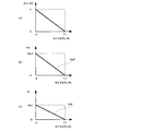
次に、電動機停止処理部10の処理動作について、図2及び図3を参照して説明する。図2は、電動機停止処理を示すフローチャートである。図3(a)は、タイマカウンタtに対する比例ゲイン設定係数G1及び積分ゲイン設定係数G2を示す図である。図3(b)は、タイマカウンタtに対する比例ゲインKpを示す図である。図3(c)は、タイマカウンタtに対する積分ゲインKiを示す図である。
(8) Processing Operation of Motor Stop Processing Unit 10 Next, the processing operation of the motor stop processing unit 10 will be described with reference to FIGS. FIG. 2 is a flowchart showing the motor stop process. FIG. 3A shows a proportional gain setting coefficient G1 and an integral gain setting coefficient G2 for the timer counter t. FIG. 3B shows the proportional gain Kp for the timer counter t. FIG. 3C shows the integral gain Ki for the timer counter t.
電動機停止処理部10は、まず、停止指示信号検出部101にて停止指示信号を検出する(ステップS1)。続いて、停止指示信号が検出されたか否かを判断する(ステップS2)。そして、停止指示信号が検出されていない場合には(ステップS2:No)、ゲイン設定部104にて通常比例ゲインKp1及び通常積分ゲインKi1をPI制御部4の比例要素の比例ゲインKp及び積分要素の積分ゲインKiとして設定する(ステップS3)。そして、処理を終了する。
First, the motor stop processing unit 10 detects a stop instruction signal by the stop instruction signal detection unit 101 (step S1). Subsequently, it is determined whether or not a stop instruction signal is detected (step S2). When the stop instruction signal is not detected (step S2: No), the
一方、停止指示信号が検出された場合には(ステップS2:Yes)、目標電流値判定部102が目標電流Im*を読み込む(ステップS4)。続いて、目標電流値判定部102にて、読み込まれた目標電流Im*の絶対値と予め記憶された判定電流Im0とを比較して、目標電流Im*の絶対値が判定電流Im0より大きいか否かを判定する(ステップS5)。そして、この判定結果がゲイン設定部104及び電動機駆動停止部105に出力される。
On the other hand, when the stop instruction signal is detected (step S2: Yes), the target current
そして、目標電流Im*の絶対値が判定電流Im0以下の場合には(ステップS5:No)、電動機駆動停止部105がアシスト電動機6の駆動を停止する処理を行う(ステップS10)。すなわち、停止指示信号が検出され、かつ、目標電流Im*の絶対値が判定電流Im0以下の場合に、アシスト電動機6の駆動が停止される。
If the absolute value of the target current Im * is equal to or smaller than the determination current Im0 (step S5: No), the motor
一方、目標電流Im*の絶対値が判定電流Im0より大きい場合には(ステップS5:Yes)、ゲイン設定部104にて、停止指示信号の種類に応じて、比例ゲイン設定係数G1、積分ゲイン設定係数G2、及び所定カウンタT1を設定する(ステップS6)。さらに、上記場合には、電動機駆動停止部105にて、所定カウンタT1を設定する(ステップS6)。ここで、比例ゲイン設定係数G1及び積分ゲイン設定係数G2は、それぞれ停止比例ゲインKp2及び停止積分ゲインKi2を設定する際に用いられる。また、所定カウンタT1は、タイマ103のタイマカウンタtとの比較によりアシスト電動機6を停止するか否かの判定に用いられる。
On the other hand, when the absolute value of the target current Im * is larger than the determination current Im0 (step S5: Yes), the
ここで、比例ゲイン設定係数G1及び積分ゲイン設定係数G2について図3(a)を参照して説明する。図3(a)に示すように、比例ゲイン設定係数G1及び積分ゲイン設定係数G2は、タイマカウンタtが0のときに1とし、タイマカウンタtが所定カウンタT1のときに0となるように線形的に減少する関係とする。 Here, the proportional gain setting coefficient G1 and the integral gain setting coefficient G2 will be described with reference to FIG. As shown in FIG. 3A, the proportional gain setting coefficient G1 and the integral gain setting coefficient G2 are linear so that they are 1 when the timer counter t is 0 and 0 when the timer counter t is the predetermined counter T1. The relationship decreases.
続いて、ゲイン設定部104にて、停止比例ゲインKp2及び停止積分ゲインKi2を数1に基づき算出する。そして、算出された停止比例ゲインKp2及び停止積分ゲインKi2をPI制御部4の比例要素の比例ゲインKp及び積分要素の積分ゲインKiとして設定する(ステップS7)。
Subsequently, the
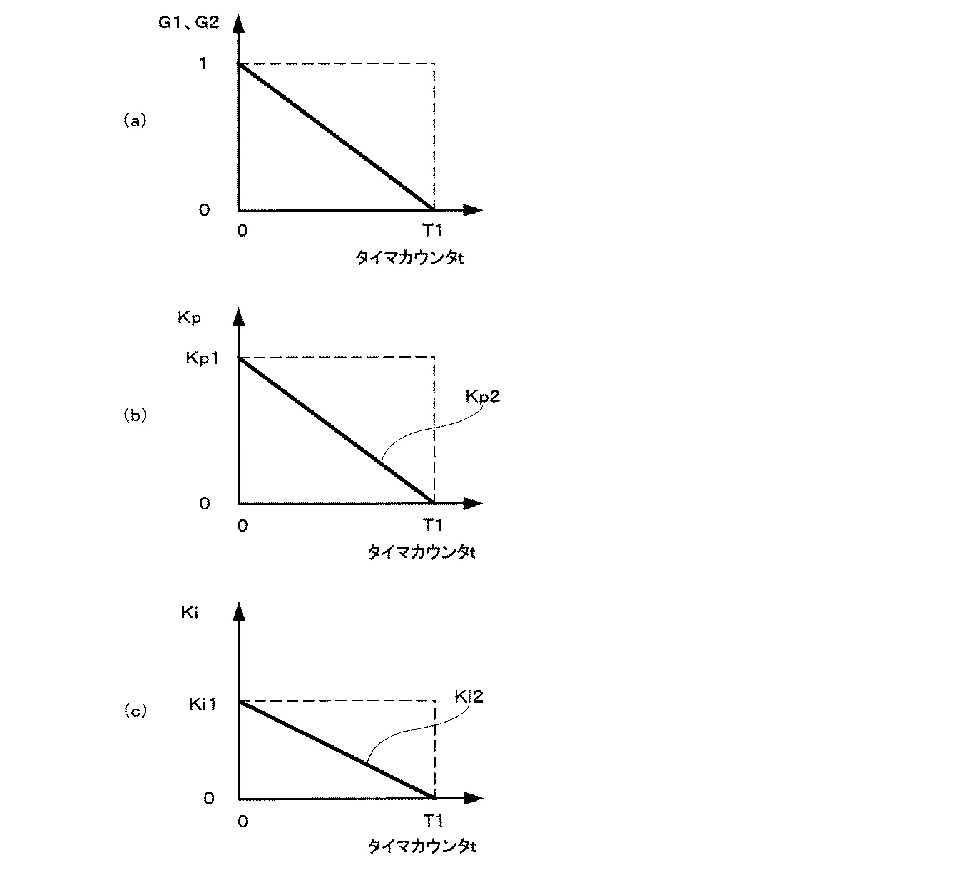
ここで、比例ゲイン設定係数G1及び積分ゲイン設定係数G2は、上述したように、タイマカウンタtの増加に伴い線形的に減少する関係からなる。従って、数1に基づき算出された停止比例ゲインKp2及び停止積分ゲインKi2は、図3(b)(c)に示すように、タイマカウンタtが0のときには通常比例ゲインKp1及び通常積分ゲインKi1となり、タイマカウンタtの増加に伴い線形的に減少して所定カウンタT1に到達する時には0(零)となる。つまり、停止比例ゲインKp2及び停止積分ゲインKi2は、それぞれ通常比例ゲインKp1及び通常積分ゲインKi1よりも小さな値からなる。
Here, as described above, the proportional gain setting coefficient G1 and the integral gain setting coefficient G2 are linearly decreased as the timer counter t increases. Accordingly, the stop proportional gain Kp2 and the stop integral gain Ki2 calculated based on
そして、停止比例ゲインKp2及び停止積分ゲインKi2を設定した後は、タイマ103のタイマカウンタtのカウントアップを開始する(ステップS8)。続いて、電動機駆動停止部105にて、タイマ103のタイマカウンタtと上述したように設定された所定カウンタT1とを比較して、タイマカウンタtが所定カウンタT1以上であるか否かを判定する(ステップS9)。
Then, after setting the stop proportional gain Kp2 and the stop integral gain Ki2, the timer counter t of the
そして、タイマカウンタtが所定カウンタT1より小さい場合には(ステップS9:No)、そのまま処理を終了する。一方、タイマカウンタtが所定カウンタT1以上に達すると(ステップS9:Yes)、電動機駆動停止部105はアシスト電動機6の駆動を停止する処理を行う(ステップS10)。すなわち、停止指示信号を検出してから所定カウンタT1に相当する時間が経過したときに、アシスト電動機6の駆動が停止される。その間、比例ゲインKp及び積分ゲインKiは、時間経過に伴い線形的に減少させている。
If the timer counter t is smaller than the predetermined counter T1 (step S9: No), the process is terminated as it is. On the other hand, when the timer counter t reaches the predetermined counter T1 or more (step S9: Yes), the motor
(9)上記実施例の変形態様
上記実施例の電動機停止処理部10は、目標電流値判定部102において目標電流Im*の絶対値が判定電流Im0より大きいか否かを判定し、ゲイン設定部104及び電動機駆動停止部105において当該判定結果に基づきゲインの設定及びアシスト電動機6の停止処理を行うようにしたが、これに限られるものではない。
(9) Modification of the above embodiment The motor stop processing unit 10 of the above embodiment determines whether or not the absolute value of the target current Im * is larger than the determination current Im0 in the target current
例えば、上記実施例の目標電流値判定部102を操舵トルク値判定部に置き換えるようにしてもよい。操舵トルク値判定部は、操舵トルクセンサ1により検出された操舵トルクTsを入力する。そして、操舵トルク値判定部は、入力された操舵トルクTsの絶対値と予め記憶している判定トルク値(所定トルク閾値)Ts0とを比較して、操舵トルクTsの絶対値が判定トルク値Ts0より大きいか否かを判定する。そして、その判定結果をゲイン設定部104及び電動機駆動停止部105に出力する。なお、判定トルク値Ts0は、判定トルク値Ts0に基づき設定された目標電流Im*に相当する電流がアシスト電動機6に供給されている場合に、アシスト電動機6への電流供給を遮断したとしても、運転者による操舵力が大きく増加することなく、操舵フィーリングを低下させない程度の操舵トルク値としている。
For example, the target current
そして、この場合には、ゲイン設定部104及び電動機駆動停止部105は、操舵トルク値判定部による判定結果に基づき、ゲインの設定及びアシスト電動機6の駆動停止処理を行う。具体的には、操舵トルクTsが判定トルク値Ts0以下の場合に、電動機駆動停止部105はアシスト電動機6の駆動を停止する処理を行う。また、操舵トルクTsが判定トルク値Ts0より大きい場合には、図2のステップS6以降の処理が行われる。
In this case, the
また、上記実施例のゲイン設定部104は、数1に基づき停止比例ゲインKp2及び停止積分ゲインKi2を設定したが、これに限られるものではない。例えば、停止比例ゲインKp2及び停止積分ゲインKi2は、予め記憶された経過時間に対する各ゲインのマップに基づき決定するようにしてもよい。また、停止比例ゲインKp2及び停止積分ゲインKi2は、時間経過に伴い曲線的に小さくなるような関係式やマップなどに基づき算出するようにしてもよい。
In addition, the
1:操舵トルクセンサ(操舵トルク検出手段)、 2:目標電流設定部(目標電流設定手段)、 3:減算器、 4:PI制御部(比例積分制御手段)、 5:インバータ駆動部(電動機駆動手段)、 6:アシスト電動機、 7:電動機電流検出部(電動機電流検出手段)、 8:IGスイッチ、 9:故障診断部、 10:電動機停止処理部、 101:停止指示信号検出部(停止指示信号検出手段)、 102:目標電流値判定部、 103:タイマ、 104:ゲイン設定部(ゲイン設定手段)、 105:電動機駆動停止部(駆動停止手段) 1: Steering torque sensor (steering torque detection means) 2: Target current setting section (target current setting means) 3: Subtractor 4: PI control section (proportional integration control means) 5: Inverter drive section (motor drive) Means), 6: assist motor, 7: motor current detection unit (motor current detection unit), 8: IG switch, 9: failure diagnosis unit, 10: motor stop processing unit, 101: stop instruction signal detection unit (stop instruction signal) Detection means), 102: target current value determination section, 103: timer, 104: gain setting section (gain setting means), 105: motor drive stop section (drive stop means)
Claims (6)
ステアリング軸にかかる操舵トルクを検出する操舵トルク検出手段と、
前記操舵トルクに基づき前記アシスト電動機に供給する目標電流を設定する目標電流設定手段と、
前記アシスト電動機に流れる電動機電流を検出する電動機電流検出手段と、
前記目標電流と前記電動機電流との偏差に基づき比例要素及び積分要素の少なくとも一方を含む比例積分制御手段と、
前記比例積分制御手段の出力に基づき前記アシスト電動機を駆動する電動機駆動手段と、
を備える電動パワーステアリング装置において、
さらに、
前記アシスト電動機の停止指示信号を検出する停止指示信号検出手段と、
前記停止指示信号を検出した場合に前記比例ゲイン及び/又は前記積分ゲインを時間経過に伴い小さくするゲイン設定手段と、
前記停止指示信号を検出してから所定時間経過した場合に前記アシスト電動機の駆動を停止させる駆動停止手段と、
を備えることを特徴とする電動パワーステアリング装置。 An assist motor to assist the steering force;
Steering torque detecting means for detecting steering torque applied to the steering shaft;
Target current setting means for setting a target current to be supplied to the assist motor based on the steering torque;
Motor current detection means for detecting a motor current flowing in the assist motor;
Proportional-integral control means including at least one of a proportional element and an integral element based on a deviation between the target current and the motor current;
Motor drive means for driving the assist motor based on the output of the proportional-integral control means;
In an electric power steering apparatus comprising:
further,
A stop instruction signal detecting means for detecting a stop instruction signal of the assist motor;
Gain setting means for reducing the proportional gain and / or the integral gain with time when the stop instruction signal is detected;
Drive stopping means for stopping the driving of the assist motor when a predetermined time has elapsed after detecting the stop instruction signal;
An electric power steering apparatus comprising:
前記比例ゲイン及び/又は前記積分ゲインは、それぞれの前記異常状態に応じて異なることを特徴とする請求項1又は2に記載の電動パワーステアリング装置。 The stop instruction signal is an abnormality detection signal for detecting a plurality of abnormal states of the electric power steering device,
3. The electric power steering apparatus according to claim 1, wherein the proportional gain and / or the integral gain differs depending on each of the abnormal states.
前記比例ゲイン及び/又は前記積分ゲインは、前記異常状態及び前記オフ信号に応じて異なることを特徴とする請求項1又は2に記載の電動パワーステアリング装置。 The stop instruction signal is an abnormality detection signal for detecting at least one abnormal state of the electric power steering device and an off signal of an ignition switch,
3. The electric power steering apparatus according to claim 1, wherein the proportional gain and / or the integral gain differs according to the abnormal state and the off signal. 4.
前記所定時間は、それぞれの前記異常状態に応じて異なることを特徴とする請求項1又は2に記載の電動パワーステアリング装置。 The stop instruction signal is an abnormality detection signal for detecting a plurality of abnormal states of the electric power steering device,
The electric power steering apparatus according to claim 1 or 2, wherein the predetermined time varies depending on each of the abnormal states.
前記所定時間は、前記異常状態及び前記オフ信号に応じて異なることを特徴とする請求項1又は2に記載の電動パワーステアリング装置。 The stop instruction signal is an abnormality detection signal for detecting at least one abnormal state of the electric power steering device and an off signal of an ignition switch,
The electric power steering apparatus according to claim 1, wherein the predetermined time varies depending on the abnormal state and the off signal.
Priority Applications (1)
| Application Number | Priority Date | Filing Date | Title |
|---|---|---|---|
| JP2004254714A JP2006069352A (en) | 2004-09-01 | 2004-09-01 | Electric power steering device |
Applications Claiming Priority (1)
| Application Number | Priority Date | Filing Date | Title |
|---|---|---|---|
| JP2004254714A JP2006069352A (en) | 2004-09-01 | 2004-09-01 | Electric power steering device |
Publications (1)
| Publication Number | Publication Date |
|---|---|
| JP2006069352A true JP2006069352A (en) | 2006-03-16 |
Family
ID=36150419
Family Applications (1)
| Application Number | Title | Priority Date | Filing Date |
|---|---|---|---|
| JP2004254714A Pending JP2006069352A (en) | 2004-09-01 | 2004-09-01 | Electric power steering device |
Country Status (1)
| Country | Link |
|---|---|
| JP (1) | JP2006069352A (en) |
Cited By (7)
| Publication number | Priority date | Publication date | Assignee | Title |
|---|---|---|---|---|
| FR2907411A1 (en) * | 2006-10-23 | 2008-04-25 | Renault Sas | Electro-pump group piloting method for electro-hydraulic power steering system of motor vehicle, involves controlling motor during period according to preset of current consumed by motor, in case of disconnection of signal connector |
| KR100854765B1 (en) | 2007-03-29 | 2008-08-27 | 주식회사 만도 | Method and device for controlling motor by using interlock circuit in vehicle steering system |
| JP2010111230A (en) * | 2008-11-05 | 2010-05-20 | Toyota Motor Corp | Vehicle control device, brake electronic control device, and electric power steering device |
| JP2012143100A (en) * | 2011-01-05 | 2012-07-26 | Mitsutoyo Corp | Control device, and measuring apparatus |
| JP2012224183A (en) * | 2011-04-19 | 2012-11-15 | Nippon Yusoki Co Ltd | Electric power steering device |
| US8423257B2 (en) | 2010-03-17 | 2013-04-16 | Honda Motor Co., Ltd. | System for and method of maintaining a driver intended path |
| CN107010099A (en) * | 2015-09-18 | 2017-08-04 | 蒂森克虏伯普利斯坦股份公司 | Steering assistance is left using the emergent of motor current of estimation |
-
2004
- 2004-09-01 JP JP2004254714A patent/JP2006069352A/en active Pending
Cited By (11)
| Publication number | Priority date | Publication date | Assignee | Title |
|---|---|---|---|---|
| FR2907411A1 (en) * | 2006-10-23 | 2008-04-25 | Renault Sas | Electro-pump group piloting method for electro-hydraulic power steering system of motor vehicle, involves controlling motor during period according to preset of current consumed by motor, in case of disconnection of signal connector |
| WO2008050021A2 (en) | 2006-10-23 | 2008-05-02 | Renault S.A.S. | Method for driving an electrically operated pump unit of a motor vehicle electrohydraulic power-assisted steering system |
| WO2008050021A3 (en) * | 2006-10-23 | 2008-06-12 | Renault Sa | Method for driving an electrically operated pump unit of a motor vehicle electrohydraulic power-assisted steering system |
| KR100854765B1 (en) | 2007-03-29 | 2008-08-27 | 주식회사 만도 | Method and device for controlling motor by using interlock circuit in vehicle steering system |
| JP2010111230A (en) * | 2008-11-05 | 2010-05-20 | Toyota Motor Corp | Vehicle control device, brake electronic control device, and electric power steering device |
| US8423257B2 (en) | 2010-03-17 | 2013-04-16 | Honda Motor Co., Ltd. | System for and method of maintaining a driver intended path |
| US9079585B2 (en) | 2010-03-17 | 2015-07-14 | Honda Motor Co., Ltd. | System for and method of maintaining a driver intended path |
| US9168923B2 (en) | 2010-03-17 | 2015-10-27 | Honda Motor Co., Ltd. | System for and method of maintaining a driver intended path |
| JP2012143100A (en) * | 2011-01-05 | 2012-07-26 | Mitsutoyo Corp | Control device, and measuring apparatus |
| JP2012224183A (en) * | 2011-04-19 | 2012-11-15 | Nippon Yusoki Co Ltd | Electric power steering device |
| CN107010099A (en) * | 2015-09-18 | 2017-08-04 | 蒂森克虏伯普利斯坦股份公司 | Steering assistance is left using the emergent of motor current of estimation |
Similar Documents
| Publication | Publication Date | Title |
|---|---|---|
| US6816765B2 (en) | Motor-driven power steering control apparatus | |
| JP4177387B2 (en) | Motor control device | |
| JPH08244634A (en) | Motor-driven power steering controller | |
| US7537082B2 (en) | Electric power steering system | |
| JP3678097B2 (en) | Electric power steering device | |
| WO2006123839A1 (en) | Electric power steering system device controller | |
| JP5286981B2 (en) | Electric power steering device | |
| US20020189893A1 (en) | Electric power steering apparatus | |
| JP2002067988A (en) | Motor-driven power steering device | |
| JP2006069352A (en) | Electric power steering device | |
| JP4923785B2 (en) | Control method and apparatus for electric power steering apparatus | |
| JP5119930B2 (en) | Electric power steering device | |
| JP2004196128A (en) | Electric power steering device | |
| JP2002053057A (en) | Electric power steering device | |
| JP2009067222A (en) | Electric power steering device | |
| JP2007283916A (en) | Electric power steering control device and method | |
| CN107529350B (en) | Electric power steering apparatus | |
| CN110871840B (en) | Vehicle control device | |
| JP2006076331A (en) | Electric power steering device | |
| KR100987641B1 (en) | Fail safe control method in eps system | |
| JP5035744B2 (en) | Electric power steering control device and method | |
| JP4853043B2 (en) | Control device for electric power steering device | |
| JP2004306858A (en) | Electric power steering device | |
| JP5169411B2 (en) | Electric power steering device | |
| JP2008049779A (en) | Electric power steering control device |
Legal Events
| Date | Code | Title | Description |
|---|---|---|---|
| A711 | Notification of change in applicant |
Effective date: 20060523 Free format text: JAPANESE INTERMEDIATE CODE: A712 |
|
| A711 | Notification of change in applicant |
Free format text: JAPANESE INTERMEDIATE CODE: A711 Effective date: 20060811 |