JP2006065731A - Label pasting apparatus and its control method - Google Patents
Label pasting apparatus and its control method Download PDFInfo
- Publication number
- JP2006065731A JP2006065731A JP2004249810A JP2004249810A JP2006065731A JP 2006065731 A JP2006065731 A JP 2006065731A JP 2004249810 A JP2004249810 A JP 2004249810A JP 2004249810 A JP2004249810 A JP 2004249810A JP 2006065731 A JP2006065731 A JP 2006065731A
- Authority
- JP
- Japan
- Prior art keywords
- antenna
- rfid tag
- label
- writing
- reading
- Prior art date
- Legal status (The legal status is an assumption and is not a legal conclusion. Google has not performed a legal analysis and makes no representation as to the accuracy of the status listed.)
- Granted
Links
Images


Abstract
Description
本発明は、印刷されたラベル内のRFIDタグに接続されたアンテナで書き込み/読み込みを行うRFID書き込み/読み込み手段を有するラベル貼付装置およびその制御方法において、特にRFID書き込み/読み込み手段に接続されたアンテナを切り替えて使用するラベル貼付装置およびその制御方法に関する。
The present invention relates to a label attaching apparatus having an RFID writing / reading means for writing / reading with an antenna connected to an RFID tag in a printed label, and a control method therefor, particularly an antenna connected to the RFID writing / reading means. The present invention relates to a label sticking device that is used by switching between and a control method thereof.
近年、商品の在庫管理や販売管理等を容易にすべく、ICチップとアンテナから成り非接触で情報の電気的な書き込み/読み込みを可能とするRFID(Radio Frequency IDentification)タグが開発されている。このRFIDタグは、ICチップに大容量の情報を記録することができ、無線により非接触で情報を送受信することができるものである。
このRFIDタグを、ラベル貼付装置で使用する商品ラベルや台紙が無い台紙無しラベルなどのラベルに内包し、このラベルを商品に直接貼付して、または商品が梱包された段ボール等に貼付することで、ラベル表面に印刷された視認情報とRFIDタグのICチップに書き込まれた個別管理情報により、在庫管理や販売管理等を容易に行うものである。
上記ラベルの表面に印刷される視認情報としては、商品を模った図柄、出産地およびキャッチフレーズ等が印刷され、内包するRFIDタグには、商品番号や製造番号および生産履歴情報等から成る個別管理情報が書き込まれる。
2. Description of the Related Art In recent years, RFID (Radio Frequency IDentification) tags, which are composed of an IC chip and an antenna and enable electrical writing / reading of information without contact, have been developed in order to facilitate inventory management and sales management of products. This RFID tag can record a large amount of information on an IC chip and can transmit and receive information wirelessly in a non-contact manner.
By enclosing this RFID tag in a label such as a product label used in a label applicator or a label without a mount, and affixing this label directly to the product, or affixing to a cardboard etc. in which the product is packed In addition, inventory management and sales management can be easily performed using the visual information printed on the label surface and the individual management information written on the IC chip of the RFID tag.
As the visual information printed on the surface of the label, a design imitating a product, the place of birth, a catchphrase, etc. are printed, and the RFID tag to be included is an individual management consisting of product number, manufacturing number, production history information, etc. Information is written.
図1は、RFIDタグを内包するラベル用紙の概略説明図であり、図1(a)は、商品ラベル用紙の構成を説明するための説明図、図1(b)は、商品ラベル用紙の層を説明するための説明図、図1(c)は、台紙無しラベル用紙の構成を説明するための説明図、図1(d)は、台紙無しラベル用紙の層を説明するための説明図である。
図1の(a)に示すように、商品ラベル用紙YLは、表面が印刷層L1で裏面が粘着層L2から成るラベルLが帯状の台紙Dに等間隔で仮着されており、ラベルLの印刷層L1と粘着層L2の間にICチップR1とアンテナR2から成るRFIDタグRが内包されている。この商品ラベル用紙YLは、ラベルLの印刷層L1に予め貼付する商品を模った図柄、出産地およびキャッチフレーズ等が印刷されており、ラベルLを台紙Dより剥離し商品に直接貼付して、または商品が梱包された段ボール等に貼付して使用される。
図1の(b)に示すように、台紙無しラベル用紙YNは、表面がシリコン層N11と印刷層N12から成る表示層N1と裏面が粘着層N2とから成るラベルNが帯状に形成されており、印刷層N11と粘着層N2の間にICチップR1とアンテナR2から成るRFIDタグRが内包されている。また、台紙無しラベル用紙YNは、切断位置N3により切断された後、ラベルNを商品に直接貼付して、または商品が梱包された段ボール等に貼付して使用される。
また、RFIDタグのサイズはカードサイズ(縦54mm×横86mm)が主流であるが、RFIDタグのICチップとアンテナの改良による小型化が進んでおり、年々、用紙サイズが小さいものに内包可能になってきている。
FIG. 1 is a schematic explanatory diagram of a label sheet containing an RFID tag. FIG. 1A is an explanatory diagram for explaining a configuration of a product label sheet, and FIG. 1B is a layer of the product label sheet. FIG. 1C is an explanatory diagram for explaining the configuration of the label paper without the mount, and FIG. 1D is an explanatory diagram for explaining the layers of the label paper without the mount. is there.
As shown in FIG. 1A, the product label paper YL has a label L, which has a printed layer L1 on the front side and an adhesive layer L2 on the back side, temporarily attached to the belt-like mount D at equal intervals. An RFID tag R including an IC chip R1 and an antenna R2 is included between the print layer L1 and the adhesive layer L2. This product label paper YL is printed with a pattern imitating the product to be affixed in advance to the printed layer L1 of the label L, the place of birth, a catchphrase, etc. Or, it is used by sticking to a cardboard or the like in which products are packed.
As shown in FIG. 1 (b), the non-mounting label paper YN has a belt-like label N having a display layer N1 having a silicon layer N11 and a printing layer N12 on the front surface and an adhesive layer N2 on the back surface. An RFID tag R including an IC chip R1 and an antenna R2 is included between the printing layer N11 and the adhesive layer N2. Further, the label paper YN without the mount is used after being cut at the cutting position N3 and then sticking the label N directly to the product, or sticking it to a cardboard or the like on which the product is packed.
The main size of RFID tags is card size (length 54mm x width 86mm), but the miniaturization is progressing by improving the IC chip and antenna of the RFID tag. It has become to.
図2は、RFIDタグのICチップにある記憶メモリの概略構成図である。
図中の記憶メモリの先頭にはヘッダブロックがあり、固定情報の“E0”とRFIDタグのIC製造者コード、IC製造者シリアル番号等から成る固有識別情報(Unique IDentifier)ブロックと、応用分野識別情報(Application Family Identifier)やデータ記憶形式識別情報(Data Storage Format IDentifier)等から成る拡張ブロックがあり、以降は、可変情報の書き込み/読み込みが可能な記憶メモリから構成されており、この記憶メモリには、商品番号や製造番号および生産履歴情報等から成る個別管理情報が書き込まれ記憶される。
ヘッダブロックの内容は、RFIDタグの製造元でRFIDタグのICチップ内に書き込まれるもので、固有識別情報のIC製造者コードやIC製造者シリアル番号は、RFIDタグの製造元で同一の番号が無いように付番される。
また、ICチップに書き込まれた固有識別情報は、RFIDタグの製造工程やRFIDを内包させるためのラベル用紙の製造工程により、連番状態では無く不規則な付番となっている。
FIG. 2 is a schematic configuration diagram of a storage memory in the IC chip of the RFID tag.
There is a header block at the top of the storage memory in the figure, a unique identification information (Unique IDentifier) block consisting of fixed information “E0”, IC manufacturer code of RFID tag, IC manufacturer serial number, etc., and application field identification There is an expansion block consisting of information (Application Family Identifier), data storage format identification information (Data Storage Format IDentifier), etc., and thereafter, it is composed of a storage memory that can write / read variable information. The individual management information including the product number, the production number, and the production history information is written and stored.
The contents of the header block are written in the IC tag of the RFID tag by the RFID tag manufacturer, and the IC manufacturer code and IC manufacturer serial number of the unique identification information do not seem to have the same number by the RFID tag manufacturer. Numbered.
Further, the unique identification information written in the IC chip is an irregular number, not a serial number state, due to the RFID tag manufacturing process or the label sheet manufacturing process for including the RFID.
上記構成のRFIDタグは、衝撃や静電気に弱いと言う問題を抱えており、用紙搬送の上流側と下流側にリーダライタ装置からのアンテナをそれぞれ配置し、用紙搬送の上流側または下流側でRFIDタグへの読み書きを可能としたRFIDラベルプリンタが知られている(例えば、特許文献1参照)。
このRFIDラベルプリンタは、例えば、上流側のリーダライタ装置に接続されているアンテナでRFIDタグに情報を書き込み、サーマルヘッドによりRFIDラベルに印字を行い、下流側のリーダライタ装置に接続されているアンテナでRFIDタグに書き込まれた情報を読み込み、RFIDタグに書き込んだ情報と比較することで、RFIDタグに正しく情報が書き込まれていることを確認できるものである。
The RFID tag configured as described above has a problem that it is vulnerable to shock and static electricity, and an antenna from the reader / writer device is arranged on the upstream side and the downstream side of the paper transport, respectively, and the RFID tag is located upstream or downstream of the paper transport. An RFID label printer capable of reading and writing to a tag is known (for example, see Patent Document 1).
In this RFID label printer, for example, an antenna connected to the reader / writer device on the upstream side writes information on the RFID tag with an antenna connected to the reader / writer device on the upstream side, prints the RFID label with a thermal head, and is connected to the reader / writer device on the downstream side. By reading the information written in the RFID tag and comparing it with the information written in the RFID tag, it can be confirmed that the information is correctly written in the RFID tag.
また、プリンタ内にあるRFIDラベルへデータの書き込みを行い、失敗した時にRFIDラベルへ特殊パターンを印字して、不良なRFIDラベルであることを報知するRFID読み込み/書き込み装置付きプリンタが知られている(例えば、特許文献2参照)。
しかしながら、上記特許文献1のRFIDラベルプリンタは、カードサイズのRFIDタグが内包されたラベル用紙を考慮したもので、具体的には、上流側にあるリーダライタ装置に接続されたアンテナの上にラベルが1枚、サーマルヘッドとプラテンからなる印字手段にラベルが1枚、下流側にあるリーダライタ装置に接続されたアンテナの上にラベルが1枚となるように配置されている。つまり、上流側および下流側の各アンテナで認識できるRFIDタグは各々1枚であるように各アンテナと印字手段を配置することにより、リーダライタ装置に接続されたアンテナで複数枚のラベル用紙を誤認しないようにしている。
そのため、上記特許文献1のRFIDラベルプリンタにおいて、各アンテナの配置やサーマルヘッド等から成る印字手段の配置などプリンタのメカ設計が制限されることで、大型化や汎用性が欠けるなどの問題がある。
さらに、アンテナに反応する交信領域内に複数のRFIDタグを内包したラベルがある場合に対応できない、また、カードサイズとは異なるサイズのRFIDタグを内包したラベルに対応できない問題がある。
However, the RFID label printer of the above-mentioned
For this reason, the RFID label printer disclosed in
Furthermore, there is a problem that it is not possible to deal with a case where there is a label including a plurality of RFID tags in the communication area that reacts to the antenna, and it is impossible to cope with a label including an RFID tag having a size different from the card size.
また、上記特許文献2のプリンタは、書き込み不良が合ったラベルを検出した場合、不良ラベルに特殊パターンを印字して不良ラベルである旨を報知することができるが、印字ヘッドを必要とせず予め印刷されたラベルを貼付するだけのラベル貼付装置では、RFIDタグへの書き込み不良があったラベルを検出した場合に、報知する手段が無い問題があった。
さらに、上記ラベル貼付装置において、RFIDタグを内包したラベル用紙を使用する上で、ラベル用紙の紙厚や層の構成、サイズおよびRFIDタグのICチップやアンテナの形状や材質、サイズなどの種類の増加に伴い、ラベル用紙の供給部からラベル貼付部までラベル用紙を搬送する搬送路が長いラベル貼付装置では、ラベル用紙の搬送路途中に蛇行を防止しするための用紙ガイドや、ラベル用紙に均一にテンションをかけるための複数のテンション・ローラにより、ラベル用紙の搬送途中でRFIDタグが故障してしまう場合が考えられる他、RFIDリーダライタと接続されたアンテナの不良などの要因もあり、従来のラベル貼付装置では、どの工程でエラーが発生したか特定できない問題がある。
したがって、どの工程でエラーが発生したか特定ができないことから、対応するまでに時間がかかるなどの問題が考えられる。
In addition, when the printer of
Furthermore, in the label sticking apparatus, when using label paper containing an RFID tag, the thickness of the label paper, the configuration and size of the label paper, and the shape, material, and size of the IC chip and antenna of the RFID tag Along with the increase, in label applicators that have a long transport path for transporting label paper from the label paper supply section to the label applicator, the paper guide for preventing meandering in the middle of the transport path of the label paper and the label paper are uniform. The RFID tag may break down while the label paper is being transported due to a plurality of tension rollers for applying tension to the paper, and there may be factors such as a failure of the antenna connected to the RFID reader / writer. The labeling device has a problem that it cannot be specified in which process an error has occurred.
Therefore, since it cannot be specified in which process an error has occurred, there may be a problem that it takes a long time to respond.
本発明は以上のような諸問題にかんがみなされたもので、RFID書き込み/読み込み手段と接続されるアンテナを各工程毎に設け、RFIDタグを内包したラベルを1枚毎に管理し、目的とするRFIDタグへ確実に書き込みおよび読み込みができるラベル貼付装置およびその制御方法を提供することを課題とする。
また、RFID書き込み/読み込み手段と各工程にあるアンテナとの接続を切り替える切替手段により、アンテナ同士が相互干渉することなくアンテナ毎に目的や交信領域を設定でき、RFIDタグを内包した多種多用な形態のラベルが使用できると共に、汎用性の広いラベル貼付装置のメカ設計ができるラベル貼付装置およびその制御方法を提供することを課題とする。
また、RFIDタグの書き込み/読み込みエラーが発生した場合、報知手段によりエラーがあった工程を報知するので、その対応も早急且つ柔軟に行なうことができるラベル貼付装置およびその制御方法を提供することを課題とする。
The present invention has been considered in view of the above problems. An antenna connected to an RFID writing / reading unit is provided for each process, and a label including an RFID tag is managed for each sheet. It is an object of the present invention to provide a label affixing device that can reliably write to and read from an RFID tag and a control method thereof.
In addition, the switching means for switching the connection between the RFID writing / reading means and the antenna in each process enables the purpose and communication area to be set for each antenna without mutual interference between the antennas. It is an object of the present invention to provide a label applicator and a control method therefor that can use the above-mentioned label and can perform a mechanical design of a versatile label applicator.
Further, when an RFID tag writing / reading error occurs, the notifying means notifies the process in which the error has occurred, and therefore, it is possible to provide a label sticking apparatus and a control method therefor that can be dealt with quickly and flexibly. Let it be an issue.
すなわち本発明の請求項1に記載のラベル貼付装置は、印刷されたラベル内のRFIDタグに接続されたアンテナで書き込み/読み込みを行うRFID書き込み/読み込み手段を有するラベル貼付装置であって、前記ラベルを搬送する上流側で前記RFIDタグの固有識別情報を読み込む第一のアンテナと、前記固有識別情報に基づき特定する前記RFIDタグに個別管理情報を書き込むまたは書き込みと読み込みを行なう第ニのアンテナと、前記RFID書き込み/読み込み手段と前記アンテナの何れかに接続を切り替える切替手段と、前記固有識別情報と前記個別管理情報を記憶する記憶手段とを有することを特徴とする。
請求項2に記載のラベル貼付装置は、前記第一のアンテナの近傍には、電磁波を遮断するシールド部材を有することを特徴とする。
請求項3に記載のラベル貼付装置は、前記記憶手段により記憶された前記固有識別情報と前記個別管理情報を上位ホストに返信する返信手段を有することを特徴とする。
請求項4に記載のラベル貼付装置は、前記固有識別情報に基づき特定する前記RFIDタグから前記固有識別情報または前記個別管理情報を読み込む第三のアンテナを有し、前記RFID書き込み/読み込み手段と前記第三のアンテナとの接続を前記切替手段により切り替えることを特徴とする。
請求項5に記載のラベル貼付装置は、前記RFID書き込み/読み込み手段で、前記RFIDタグへ書き込み/読み込みを行ない異常を検出した場合に、前記RFID書き込み/読み込み手段と接続されている何れの前記アンテナで異常を検出したかを報知する報知手段を有することを特徴とする。
請求項6に記載のラベル貼付装置の制御方法は、印刷されたラベル内のRFIDタグに接続されたアンテナで書き込み/読み込みを行うRFID書き込み/読み込み手段を有するラベル貼付装置の制御方法であって、前記ラベルを搬送する上流側で前記RFIDタグの固有識別情報を第一のアンテナで読み込む工程と、前記固有識別情報に基づき特定する前記RFIDタグに個別管理情報を第二のアンテナで書き込むまたは書き込みと読み込みを行なう工程と、前記RFID書き込み/読み込み手段と前記アンテナの何れかに接続を切り替える工程と、前記固有識別情報と前記個別管理情報を記憶する工程とを設けことを特徴とする。
請求項7に記載のラベル貼付装置の制御方法は、記憶された前記固有識別情報と前記個別管理情報を上位ホストに返信する返信工程を有することを特徴とする。
請求項8に記載のラベル貼付装置の制御方法は、前記固有識別情報に基づき特定する前記RFIDタグから前記固有識別情報または前記個別管理情報を第三のアンテナで読み込む工程を有し、前記第三のアンテナを使用する場合に、前記RFID書き込み/読み込み手段と前記第三のアンテナとの接続に切り替えることを特徴とする。
請求項9に記載のラベル貼付装置の制御方法は、前記RFID書き込み/読み込み手段で、前記RFIDタグへ書き込み/読み込みを行ない異常を検出した場合に、前記RFID書き込み/読み込み手段と接続されている何れの前記アンテナで異常を検出したかを報知する工程を有することを特徴とする。
That is, the label sticking device according to
The label sticking device according to
According to a third aspect of the present invention, there is provided a label sticking apparatus comprising reply means for returning the unique identification information and the individual management information stored in the storage means to an upper host.
The label sticking device according to claim 4, further comprising a third antenna that reads the unique identification information or the individual management information from the RFID tag specified based on the unique identification information, and the RFID writing / reading unit and the RFID tag The connection with the third antenna is switched by the switching means.
6. The label affixing device according to
The control method of the label sticking device according to claim 6 is a control method of the label sticking device having RFID writing / reading means for writing / reading with an antenna connected to the RFID tag in the printed label, Reading the unique identification information of the RFID tag with a first antenna on the upstream side carrying the label, and writing or writing individual management information with the second antenna to the RFID tag specified based on the unique identification information; A step of reading, a step of switching connection between the RFID writing / reading means and the antenna, and a step of storing the unique identification information and the individual management information.
According to a seventh aspect of the present invention, there is provided a label sticking apparatus control method comprising a reply step of returning the stored unique identification information and the individual management information to a host.
The label sticking apparatus control method according to claim 8, further comprising: reading the unique identification information or the individual management information from the RFID tag specified based on the unique identification information with a third antenna, When the antenna is used, the connection is switched between the RFID writing / reading means and the third antenna.
The control method of the label sticking device according to claim 9, wherein when the RFID writing / reading means performs writing / reading on the RFID tag and detects an abnormality, any one connected to the RFID writing / reading means A step of notifying whether an abnormality is detected by the antenna.
以上のように本発明のラベル貼付装置は、RFID書き込み/読み込み手段と接続されるアンテナを各工程毎に設け、RFIDタグを内包したラベルを1枚毎に管理し、目的とするRFIDタグへ確実に書き込みおよび読み込みができる。
また、RFID書き込み/読み込み手段と各工程にあるアンテナとの接続を切り替える切替手段により、アンテナ同士が相互干渉することなくアンテナ毎に目的や交信領域を設定でき、RFIDタグを内包した多種多用な形態のラベルが使用できると共に、汎用性の広いラベル貼付装置のメカ設計ができる。
また、RFIDタグの書き込み/読み込みエラーが発生した場合、報知手段によりエラーがあった工程を報知するので、その対応も早急且つ柔軟に行なうことができるなど、種々の効果を奏する。
As described above, the label affixing device of the present invention is provided with an antenna connected to the RFID writing / reading means for each process, manages a label including the RFID tag for each sheet, and reliably supplies the target RFID tag. You can write to and read from.
In addition, the switching means for switching the connection between the RFID writing / reading means and the antenna in each process enables the purpose and communication area to be set for each antenna without mutual interference between the antennas. Can be used, and the mechanical design of a versatile labeling device can be performed.
Further, when an RFID tag writing / reading error occurs, the notifying unit notifies the process in which the error has occurred, so that various effects can be achieved such that the response can be quickly and flexibly performed.
次に本発明の好ましい実施の形態を図面を用いて説明する。
尚、同様の部分には同一符号を付し、その詳述はこれを省略する。
図3は、本発明のラベル貼付装置の回路構成を説明するための説明図である。
図中の10は、本発明のラベル貼付装置を司るCPUであり、CPU10は、各種制御部のプログラムを格納するROMやフラッシュメモリ等から成る非揮発性メモリ11と、RFIDタグRから読み込んだ固有識別情報や個別管理情報を記憶するRAM12と、上位ホスト40と通信を行う外部インタフェース13と、用紙を搬送する搬送モータ1の制御を行なう搬送モータ制御部14と、各種釦と表示パネルから成る操作部2を制御する操作制御部15と、用紙の有無や一枚毎の用紙を検知する用紙検知センサ3の制御を行なうセンサ制御部16と、RIDIタグRに対し情報を読み書きするリーダライタ装置30とシリアル通信等により接続されリーダライタ装置30を制御するリーダライタ制御部17(RFID書き込み/読み込み手段)と、リーダライタ装置30とアンテナ31、32、33、34、35の接続を切り替える切替回路4(切替手段)を制御するアンテナ切替制御部18と、ラベルを物品に貼付するラベル貼付部2を制御するラベル貼付制御部19とをシステムバス20を介して制御する。
Next, preferred embodiments of the present invention will be described with reference to the drawings.
In addition, the same code | symbol is attached | subjected to the same part and the detailed description is abbreviate | omitted.
FIG. 3 is an explanatory diagram for explaining a circuit configuration of the label sticking device of the present invention.
尚、上記ではリーダライタ装置30とリーダライタ制御部17をシリアル通信等により接続すると説明したが、リーダライタ装置30の回路をリーダライタ制御部17に組み込み、システムバス20を介してCPU10と接続するように変更しても何ら差支えない。
In the above description, the reader /
図4は、本発明のラベル貼付装置で使用する管理テーブルの構成図である。
複数のレコードから成る管理テーブルKは、1レコード中にRFIDタグRのICチップR1に記憶されている固有識別情報を記憶する固有識別情報記憶部K1と、操作部2から入力された、または外部インタフェース13を介してホスト40より受信した個別管理情報を記憶する個別管理情報記憶部K2とから構成されRAM12に形成されている。
また、管理テーブルKのレコードを管理する管理ポインタP1、P2、P3もRAM12に設けられている。
FIG. 4 is a configuration diagram of a management table used in the label sticking device of the present invention.
The management table K composed of a plurality of records includes a unique identification information storage unit K1 that stores unique identification information stored in the IC chip R1 of the RFID tag R in one record, and an input from the
Management pointers P1, P2, and P3 for managing records in the management table K are also provided in the
次に図5乃至図8を用いて本発明のラベル貼付装置における第一の実施の形態を説明する。
尚、本実施の形態では、台紙Dに仮着されRFIDタグRを内包するラベルLから成る商品ラベル用紙YLを用いて説明する。
図5は、第一の実施の形態のラベル貼付装置の構成を説明するための概略説明図であり、巻回された商品ラベル用紙YLを繰り出す用紙供給部CKと、商品ラベル用紙YLを均一に張架し搬送させるためのテンションローラTR1、TR2、TR3と、ラベルLに内包されたRFIDタグRのICチップR1から固有識別情報を読み込むアンテナ31(第一のアンテナ)と、外部からの電磁波を遮断しアンテナ31に反応する交信領域を規制すると共に他のRFIDタグRからの読み込みを防止するシールド部材Sと、用紙検知センサ3と、操作部2から入力された、または外部インタフェース13を介してホスト40より受信した個別管理情報を固有識別情報に基づき特定のRFIDタグに書き込みを行なうアンテナ32(第二のアンテナ)と、固有識別情報に基づき特定のRFIDタグから個別管理情報を読み込むアンテナ33(第三のアンテナ)と、ラベルLを台紙Dより剥離する剥離板Hと、剥離されたラベルLを吸着し物品Xに貼付するラベル貼付部5と、ラベルLが剥離された台紙Dを巻き取る巻取り部Mとから構成されている。
Next, the first embodiment of the label sticking device of the present invention will be described with reference to FIGS.
In the present embodiment, a description will be given using a product label sheet YL composed of a label L temporarily attached to the mount D and including the RFID tag R.
FIG. 5 is a schematic explanatory diagram for explaining the configuration of the label affixing device according to the first embodiment. The paper supply unit CK for feeding the wound product label paper YL and the product label paper YL are made uniform. Tension rollers TR1, TR2, and TR3 for stretching and transporting, an antenna 31 (first antenna) that reads unique identification information from the IC chip R1 of the RFID tag R included in the label L, and an external electromagnetic wave The shield member S that blocks and controls the communication area that reacts to the
次にアンテナ31(第一のアンテナ)が、RFIDタグRのICチップR1から固有識別情報を読み取る動作について説明する。
アンテナ31は、他のアンテナより小型で交信領域を狭くしている。これは、目的とするRFIDタグRのICチップR1から固有識別情報を読み込み、他のRFIDタグRからの影響が無い様にしている。また、アンテナ31をシールド部材Sでシールドすることで、さらに外部からの電磁波を遮断しアンテナ31に反応する交信領域を規制すると共に他のRFIDタグRからの読み込みを防止することができ、目的とするRFIDタグRのICチップR1から固有識別情報をより確実に読み込むことができる。
Next, an operation in which the antenna 31 (first antenna) reads the unique identification information from the IC chip R1 of the RFID tag R will be described.
The
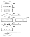
図6は、第一の実施の形態のラベル貼付装置において、RFIDタグのICチップから固有識別情報を読み取る動作について説明するためのフローチャート図である。
先ず最初にCPU10は、商品ラベル用紙YLの搬送に伴いアンテナ切替制御部18にアンテナを切り替えるよう信号を出力し、アンテナ切替制御部18は、切替回路4を介してアンテナ31とリーダライタ装置30を接続する(ステップS10)。
続いてCPU10は、リーダライタ制御部17にRFIDタグRのICチップR1より固有識別情報の読み込みを指示する。リーダライタ制御部17は、リーダライタ装置30を介してアンテナ31より固有識別情報を読み込む信号を電磁波により出力し、その旨をアンテナR2を介して受信したRFIDタグRは、ICチップR1に記憶している固有識別情報をアンテナR2を介して出力し、リーダライタ装置30は、アンテナ31を介して受信した固有識別情報をリーダライタ制御部17に出力する(ステップS11)。
FIG. 6 is a flowchart for explaining the operation of reading the unique identification information from the IC chip of the RFID tag in the label sticking device of the first embodiment.
First, the
Subsequently, the
この時、RFIDタグRからリーダライタ制御部17へ、固有識別情報と共にRFIDタグRのステータスも付加され返信されるので、CPU10は、リーダライタ制御部17を介して受信したステータスによりRFIDタグRから正しく固有識別情報が読み込まれたか否かを判断し(ステップS12)、RFIDタグRの読み込みエラーがある場合に、CPU10は、操作制御部15に信号を出力して操作部2からブザーの鳴動や“RFID リードエラー 1”などアンテナ31でエラーがあった旨を報知するメッセージを表示させる、または、外部インタフェース13を介してホスト40へ、アンテナ31でRFIDタグRの読み込みエラーが発生したステータス情報を送信する(ステップS13)。その後、処理を中断し終了する。
上記処理により、図5に示すテンションローラTR1でRFIDタグRが故障したか、アンテナ31の不良などが特定でき、テンションローラTR1の張架力を弱くする、または、材質や形状を見直す、さらに、アンテナ31を交換するなどの対応も早急且つ柔軟に行なうことができる。
ステップS12において、RFIDタグRのICチップR1より正しく固有識別情報が読み込まれた場合はステップS14へ移行する。
At this time, the status of the RFID tag R is added together with the unique identification information from the RFID tag R to the reader /
Through the above process, the RFID tag R can be broken down by the tension roller TR1 shown in FIG. 5 or the
If the unique identification information is correctly read from the IC chip R1 of the RFID tag R in step S12, the process proceeds to step S14.
ステップS14では、CPU10が、管理ポインタP1が示す管理テーブルKの固有識別情報記憶部K1に記憶された固有識別情報とリーダライタ制御部17へ読み込んだ固有識別情報とを比較し同一か否かを判定する。比較結果が同一の場合は、ステップS11より処理を繰り返し、比較結果が同一でない場合はステップS15へ進む。これにより、商品ラベル用紙YLの搬送途中で同じRFIDタグRの固有識別情報を2度読みしても、同一の固有識別情報を記憶することがないことから、RFIDタグRを内包するラベルLを1枚毎に管理することができる。
In step S14, the
ステップS15では、CPU10が、リーダライタ制御部17介して読み込んだ固有識別情報を管理ポインタP1が示す管理テーブルKの固有識別情報記憶部K1に書き込む。
上記により、各ラベルLに対応する固有識別情報を固有識別情報記憶部K1に記憶するので、RFIDタグRのICチップR1に記憶されている固有識別情報が不規則な付番であっても、確実にラベルLを1枚毎に管理することができる。
続いてCPU10は、次のレコードを示すため、管理ポインタP1をカウントアップする(ステップS16)。管理ポインタP1のカウントアップ後、管理ポインタP1の値が管理テーブルKのレコード最後尾の位置を示しているか、つまり、管理テーブルKのレコード数の最大値を示しているかを判定し(ステップS17)、管理ポインタP1の値が最大値より小さい場合は処理を終了し、管理ポインタP1の値が最大値を示している場合は、管理ポインタP1の値を初期化する(ステップS18)。これにより、管理テーブルKを循環的に使用することができRAM12のメモリ使用量を少なくする事ができる。
In step S15, the
As described above, since the unique identification information corresponding to each label L is stored in the unique identification information storage unit K1, even if the unique identification information stored in the IC chip R1 of the RFID tag R is an irregular numbering, The label L can be reliably managed for each sheet.
Subsequently, the
次にアンテナ32(第二のアンテナ)が、アンテナ31で読み込んだ固有識別情報に基づき、複数のRFIDタグRの中から特定するRFIDタグRに指定の個別管理情報を書き込む動作について説明する。
アンテナ32は、アンテナ31より大型で交信領域を広くしている。これは、カードサイズのRFIDタグRやカードサイズより大きいまたは小さなRFIDタグRを内包するラベルL、また、小さなRFIDタグRを内包する大きなラベルLなどに、柔軟に対応できるようにするためであり、その目的に合わせてアンテナ32の設置の位置や大きさを変更可能にしている。
Next, an operation in which the antenna 32 (second antenna) writes designated individual management information in the RFID tag R specified from the plurality of RFID tags R based on the unique identification information read by the
The
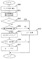
図7は、第一の実施の形態のラベル貼付装置において、RFIDタグのICチップへ個別管理情報を書き込む動作について説明ためのフローチャート図である。
先ず最初に、CPU10は、商品ラベル用紙YLの搬送に伴いアンテナ切替制御部18にアンテナを切り替えるよう信号を出力し、アンテナ切替制御部18は、切替回路4を介してアンテナ32とリーダライタ装置30を接続する(ステップS20)。
次いでCPU10は、リーダライタ制御部17に、予め操作部2からの入力、または外部インタフェース13を介してホスト40から受信し管理テーブルKの個別管理情報記憶部K2に記憶された個別管理情報の書き込みを指示する。
リーダライタ制御部17は、管理ポインタP2が示すレコードの固有識別情報記憶部K1に記憶した固有識別情報に基づきRFIDタグRを特定し、リーダライタ装置30を介してアンテナ32より個別管理情報の書き込み信号を電磁波により出力する。
固有識別情報に基づき特定されたRFIDタグRは、ICチップR1の記憶メモリに個別管理情報を記憶すると共にアンテナR2を介してステータスを出力し、リーダライタ装置30は、アンテナ32を介して受信したステータスをリーダライタ制御部17に出力する(ステップS21)。
FIG. 7 is a flowchart for explaining the operation of writing the individual management information to the IC chip of the RFID tag in the label sticking device of the first embodiment.
First, the
Next, the
The reader /
The RFID tag R specified based on the unique identification information stores the individual management information in the storage memory of the IC chip R1 and outputs the status via the antenna R2. The reader /
CPU10は、リーダライタ制御部17を介して受信したステータスを解析し、RFIDタグRへ正しく個別管理情報が書き込まれたか否かを判断し(ステップS22)、RFIDタグRの書込みエラーがある場合に、CPU10は、操作制御部15に信号を出力して操作部2からブザーの鳴動や“RFID ライトエラー 2”などアンテナ32でエラーがあった旨を報知するメッセージを表示させる、または、外部インタフェース13を介してホスト40へ、アンテナ32でRFIDタグRの書き込みエラーが発生したステータス情報を送信する(ステップS23)。その後、処理を中断し終了する。
上記処理により、図5に示すテンションローラTR2でRFIDタグRが故障したか、アンテナ32の不良などが特定でき、テンションローラTR2の張架力を弱くする、または、材質や形状を見直す、さらに、アンテナ32を交換するなどの対応も早急且つ柔軟に行なうことができる。
ステップS22において、RFIDタグRのICチップR1より正しく個別管理情報が書き込まれた場合はステップS24へ移行する。
The
Through the above processing, the RFID roller R can be broken down by the tension roller TR2 shown in FIG. 5 or the
In step S22, when the individual management information is correctly written from the IC chip R1 of the RFID tag R, the process proceeds to step S24.
ステップS24では、CPU10が、次のレコードを示すため、管理テーブルKの管理ポインタP2をカウントアップする。管理ポインタP2のカウントアップ後、管理ポインタP2の値が管理テーブルKのレコード最後尾の位置を示しているか、つまり、管理テーブルKのレコード数の最大値を示しているかを判定し(ステップS25)、管理ポインタP2の値が最大値より小さい場合は処理を終了し、管理ポインタP2の値が最大値を示している場合は、管理ポインタP2の値を初期化する(ステップS26)。
In step S24, the
次にアンテナ33(第三のアンテナ)が、アンテナ31で読み込んだ固有識別情報に基づき、複数のRFIDタグRの中から特定するRFIDタグRの個別管理情報を読み込む動作について説明する。
アンテナ33は、アンテナ31より大型で交信領域を広くしている。これは、カードサイズのRFIDタグRやカードサイズより大きいまたは小さなRFIDタグRを内包するラベルL、また、小さなRFIDタグRを内包する大きなラベルLなどに、柔軟に対応できるようにするためであり、その目的に合わせてアンテナ33の設置の位置や大きさを変更可能にしている。
Next, an operation in which the antenna 33 (third antenna) reads the individual management information of the RFID tag R specified from the plurality of RFID tags R based on the unique identification information read by the
The
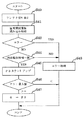
図8は、第一の実施の形態のラベル貼付装置おいて、RFIDタグのICチップから個別管理情報を読み込む動作について説明ためのフローチャート図である。
先ず最初に、CPU10は、商品ラベル用紙YLの搬送に伴いアンテナ切替制御部18にアンテナを切り替えるよう信号を出力し、アンテナ切替制御部18は、切替回路4を介してアンテナ33とリーダライタ装置30を接続する(ステップS30)。
次いでCPU10は、管理ポインタP3が示すレコードの固有識別情報記憶部K1に記憶した固有識別情報に基づきRFIDタグRを特定し、リーダライタ装置30を介してアンテナ33より個別管理情報の読み込み信号を電磁波により出力する。
固有識別情報に基づき特定されたRFIDタグRは、ICチップR1の記憶メモリに記憶している個別管理情報と共にアンテナR2を介してステータスを出力し、リーダライタ装置30は、アンテナ33を介して受信した個別管理情報とステータスをリーダライタ制御部17に出力する(ステップS31)。
FIG. 8 is a flowchart for explaining the operation of reading the individual management information from the IC chip of the RFID tag in the label sticking device of the first embodiment.
First, the
Next, the
The RFID tag R specified based on the unique identification information outputs a status via the antenna R2 together with the individual management information stored in the storage memory of the IC chip R1, and the reader /
CPU10は、リーダライタ制御部17を介して受信したステータスを解析し、RFIDタグRから正しく個別管理情報が読み込まれたか否かを判断し(ステップS32)、RFIDタグRの読み込みエラーがある場合に、CPU10は、操作制御部15に信号を出力して操作部2からブザーの鳴動や“RFID リードエラー 3”などアンテナ33でエラーがあった旨を報知するメッセージを表示させる、または、外部インタフェース13を介してホスト40へ、アンテナ33でRFIDタグRの読み込みエラーが発生したステータス情報を送信する(ステップS33)。その後、処理を中断し終了する。
上記処理により、図5に示すテンションローラTR3でRFIDタグRが故障したか、アンテナ33の不良などが特定でき、テンションローラTR3の張架力を弱くする、または、材質や形状を見直す、さらに、アンテナ33を交換するなどの対応も早急且つ柔軟に行なうことができる。
ステップS32において、RFIDタグRのICチップR1より正しく個別管理情報が読み込まれた場合はステップS34へ移行する。
The
With the above processing, the RFID tag R can be broken down by the tension roller TR3 shown in FIG. 5 or the
In step S32, when the individual management information is correctly read from the IC chip R1 of the RFID tag R, the process proceeds to step S34.
ステップS34では、CPU10が、リーダライタ制御部17を介して読み込んだ個別管理情報が、管理ポインタP3で示す管理テーブルKの個別管理情報記憶部K2に記憶された個別管理情報と一致するか否かを判定し、不一致の場合は、RFIDタグRのICチップR1に正しく個別管理情報が書き込まれていないと判定し、ステップS33へ移行し処理を終了する。また、一致する場合は、正しく個別管理情報が書き込まれたと判定しステップS35へ移行する。
続いてCPU10は、次のレコードを示すため、管理テーブルKの管理ポインタP3をカウントアップする(ステップS35)。管理ポインタP3のカウントアップ後、管理ポインタP3の値が管理テーブルKのレコード最後尾の位置を示しているか、つまり、管理テーブルKのレコード数の最大値を示しているかを判定し(ステップS36)、管理ポインタP3の値が最大値より小さい場合は処理を終了し、管理ポインタP3の値が最大値を示している場合は、管理ポインタP3の値を初期化する(ステップS37)。
In step S34, whether or not the individual management information read by the
Subsequently, the
尚、アンテナ33は、ラベル貼付装置の機構により省略しても良く、また、商品ラベル用紙YLの搬送途中にテンションローラや用紙ガイド等が多く存在するラベル貼付装置においては、上記アンテナ33を各工程に持つことで、各工程においてRFIDタグRに異常が無いかを監視できると共に、RFIDタグRでエラーがあった場合にその工程を特定できるなど、アンテナ33の数や大きさをラベル貼付装置の機構に合わせて適宜変更して差し支えない。
上記でアンテナ33を複数持つ場合は、アンテナ33をアンテナ331〜33Nとして、アンテナ切替制御部18を介して切替回路4で切り替え、管理ポインタP3をアンテナ331〜33Nの数だけ持ち、上記アンテナ33の処理を行なう様にすれば良い。
The
When there are a plurality of
従って、第一の実施の形態のラベル貼付装置により、ラベルLを物品Xに貼付する時は、以下のようにして行われる。
先ず、商品ラベル用紙YLが用紙供給部CKより搬送モータ1により繰り出され、アンテナ31によりラベルLに内包されたRFIDタグRのICチップR1に記憶された固有識別情報が、1枚のラベルL毎に読み出され管理テーブルKの固有識別管理情報K1に記憶されると共に、用紙搬送方向下流に搬送される。
次いで、アンテナ32によりアンテナ31で読み込んだ固有識別情報に基づき特定するラベルL内に内包されたRFIDタグRのICチップR1に、商品番号、製造番号および生産履歴情報等から成る個別管理情報が書き込まれる。
そして、アンテナ32より下流側のアンテナ33により、アンテナ31で読み込んだ固有識別情報に基づき特定するラベルL内に内包されたRFIDタグRのICチップR1に個別管理情報が正しく書込まれているか、また、読み込むことができるかを検証する。
上記工程でRFIDタグRへの書き込み/読み込みで異常がない場合は、表面に商品を模った図柄、生産地およびキャッチフレーズ等が印刷され内包するRFIDタグRのICチップR1に個別管理情報が書き込まれたラベルLが剥離板Hにより台紙Dより剥離され、剥離されたラベルLがラベル貼付部5により物品Xへ貼付される。
また、上記工程でRFIDタグRへの書き込み/読み込みで異常があった場合は、どの工程(アンテナ31、アンテナ32、アンテナ33)で異常を検出したかを操作部2またはホスト40へ報知する。
Therefore, when the label L is affixed to the article X by the label affixing device of the first embodiment, it is performed as follows.
First, the product label paper YL is fed from the paper supply unit CK by the
Next, individual management information including a product number, a manufacturing number, production history information, and the like is written in the IC chip R1 of the RFID tag R included in the label L specified by the
Whether the individual management information is correctly written in the IC chip R1 of the RFID tag R included in the label L specified based on the unique identification information read by the
If there is no abnormality in writing / reading to / from the RFID tag R in the above process, the individual management information is written on the IC chip R1 of the RFID tag R in which the design, production area, catchphrase, etc. imitating the product are printed and enclosed. The peeled label L is peeled from the mount D by the peeling plate H, and the peeled label L is stuck to the article X by the
In addition, when there is an abnormality in writing / reading to / from the RFID tag R in the above process, the
次に第二の実施の形態を図9乃至図11を用いて説明する。
図9は、第二の実施の形態のRFIDプリンタの構成を説明するための概略説明図である。
図中の構成は、第一の実施の形態と略同様であるが、アンテナ34とアンテナ35が異なる。
アンテナ34(第二のアンテナ)は、操作部2から入力された、または外部インタフェース13を介してホスト40より受信した個別管理情報をアンテナ31で読み込んだ固有識別情報に基づき特定のRFIDタグに書き込み/読み込みを行ない、アンテナ35(第三のアンテナ)は、アンテナ31で読み込んだ固有識別情報に基づき特定のRFIDタグから固有識別情報を読み込むために使用される。
上記の説明により、アンテナ34、アンテナ35の具体的な処理を、フローチャートを用いて説明する。
Next, a second embodiment will be described with reference to FIGS.
FIG. 9 is a schematic explanatory diagram for explaining the configuration of the RFID printer according to the second embodiment.
The configuration in the figure is substantially the same as that of the first embodiment, but the
The antenna 34 (second antenna) writes the individual management information input from the
Based on the above description, specific processing of the
それでは、アンテナ35(第三のアンテナ)が、アンテナ31で読み込んだ固有識別情報に基づき、複数のRFIDタグRの中から特定するRFIDタグRの固有識別情報を読み込む動作について説明する。
アンテナ35は、アンテナ31より大型で交信領域を広くしている。これは、カードサイズのRFIDタグRやカードサイズより大きいまたは小さなRFIDタグRを内包するラベルL、また、小さなRFIDタグRを内包する大きなラベルLなどに、柔軟に対応できるようにするためであり、その目的に合わせてアンテナ35の設置の位置や大きさを変更可能にしている。
The operation of the antenna 35 (third antenna) reading the unique identification information of the RFID tag R specified from the plurality of RFID tags R based on the unique identification information read by the
The
図10は、第二の実施の形態のラベル貼付装置おいて、RFIDタグのICチップから固有識別情報を読み込む動作について説明ためのフローチャート図である。
先ず最初に、CPU10は、商品ラベル用紙YLの搬送に伴いアンテナ切替制御部18にアンテナを切り替えるよう信号を出力し、アンテナ切替制御部18は、切替回路4を介してアンテナ35とリーダライタ装置30を接続する(ステップS40)。
次いでCPU10は、管理ポインタP3が示すレコードの固有識別情報記憶部K1に記憶した固有識別情報に基づきRFIDタグRを特定し、リーダライタ装置30を介してアンテナ35より固有識別情報の読み込み信号を電磁波により出力する。
固有識別情報に基づき特定されたRFIDタグRは、ICチップR1の記憶メモリに記憶している固有識別情報と共にアンテナR2を介してステータスを出力し、リーダライタ装置30は、アンテナ35を介して受信した個別管理情報とステータスをリーダライタ制御部17に出力する(ステップS41)。
FIG. 10 is a flowchart for explaining the operation of reading the unique identification information from the IC chip of the RFID tag in the label sticking device of the second embodiment.
First, the
Next, the
The RFID tag R specified based on the unique identification information outputs the status via the antenna R2 together with the unique identification information stored in the storage memory of the IC chip R1, and the reader /
CPU10は、リーダライタ制御部17を介して受信したステータスを解析し、RFIDタグRから正しく固有識別情報が読み込まれたか否かを判断し(ステップS42)、RFIDタグRの読み込みエラーがある場合に、CPU10は、操作制御部15に信号を出力して操作部2からブザーの鳴動や“RFID リードエラー 5”などアンテナ35でエラーがあった旨を報知するメッセージを表示させる、または、外部インタフェース13を介してホスト40へ、アンテナ35でRFIDタグRの読み込みエラーが発生したステータス情報を送信する(ステップS43)。その後、処理を中断し終了する。
上記処理により、図9に示すテンションローラTR2でRFIDタグRが故障したか、アンテナ35の不良などが特定でき、テンションローラTR2の張架力を弱くする、または、材質や形状を見直す、さらに、アンテナ35を交換するなどの対応も早急且つ柔軟に行なうことができる。
ステップS42において、RFIDタグRのICチップR1より正しく固有識別情報が読み込まれた場合はステップS44へ移行する。
The
Through the above processing, the RFID tag R has failed or the defect of the
In step S42, when the unique identification information is correctly read from the IC chip R1 of the RFID tag R, the process proceeds to step S44.
ステップS44では、CPU10が、リーダライタ制御部17を介して読み込んだ固有識別情報が、管理ポインタP3で示す管理テーブルKの固有識別情報記憶部K1に記憶された固有識別情報と一致するか否かを判定し、不一致の場合は、RFIDタグRのICチップR1が不良であると判定し、ステップS43へ移行し処理を終了する。また、一致する場合は、RFIDタグRが不良でないと判定しステップS45へ移行する。
続いてCPU10は、次のレコードを示すため、管理テーブルKの管理ポインタP3をカウントアップする(ステップS45)。管理ポインタP3のカウントアップ後、管理ポインタP3の値が管理テーブルKのレコード最後尾の位置を示しているか、つまり、管理テーブルKのレコード数の最大値を示しているかを判定し(ステップS46)、管理ポインタP3の値が最大値より小さい場合は処理を終了し、管理ポインタP3の値が最大値を示している場合は、管理ポインタP3の値を初期化する(ステップS47)。
In step S44, whether or not the unique identification information read by the
Subsequently, the
尚、アンテナ35は、ラベル貼付装置の機構により省略しても良く、また、商品ラベル用紙YLの搬送途中にテンションローラや用紙ガイド等が多く存在するラベル貼付装置においては、上記アンテナ35を各工程に持つことで、各工程においてRFIDタグRに異常が無いかを監視できると共に、RFIDタグRでエラーがあった場合にその工程を特定できるなど、アンテナ33の数や大きさをラベル貼付装置の機構に合わせて適宜変更して差し支えない。
上記でアンテナ33を複数持つ場合は、アンテナ35をアンテナ351〜35Nとして、アンテナ切替制御部18を介して切替回路4で切り替え、管理ポインタP3をアンテナ351〜35Nの数だけ持ち、上記アンテナ35の処理を行なう様にすれば良い。
The
When there are a plurality of
次にアンテナ34(第二のアンテナ)が、アンテナ31で読み込んだ固有識別情報に基づき、複数のRFIDタグRの中から特定するRFIDタグRに指定の個別管理情報を書き込みと読み込みを行なう動作について説明する。
アンテナ34は、アンテナ31より大型で交信領域を広くしている。これは、カードサイズのRFIDタグRやカードサイズより大きいまたは小さなRFIDタグRを内包するラベルL、また、小さなRFIDタグRを内包する大きなラベルLなどに、柔軟に対応できるようにするためであり、その目的に合わせてアンテナ34の設置の位置や大きさを変更可能にしている。
Next, an operation in which the antenna 34 (second antenna) writes and reads designated individual management information to the RFID tag R specified from the plurality of RFID tags R based on the unique identification information read by the
The
図11は、第二の実施の形態のラベル貼付装置において、RFIDタグのICチップへ個別管理情報の書き込みと読み込みを行なう動作について説明ためのフローチャート図である。
先ず最初に、CPU10は、商品ラベル用紙YLの搬送に伴いアンテナ切替制御部18にアンテナを切り替えるよう信号を出力し、アンテナ切替制御部18は、切替回路4を介してアンテナ34とリーダライタ装置30を接続する(ステップS50)。
次いでCPU10は、リーダライタ制御部17に、予め操作部2からの入力、または外部インタフェース13を介してホスト40から受信した管理テーブルKの個別管理情報記憶部K2に記憶されている個別管理情報の書き込みを指示する。
リーダライタ制御部17は、管理ポインタP2が示すレコードの固有識別情報記憶部K1に記憶した固有識別情報に基づきRFIDタグRを特定し、リーダライタ装置30を介してアンテナ34より個別管理情報の書き込み信号を電磁波により出力する。
固有識別情報に基づき特定されたRFIDタグRは、ICチップR1の記憶メモリに個別管理情報を記憶すると共にアンテナR2を介してステータスを出力し、リーダライタ装置30は、アンテナ34を介して受信したステータスをリーダライタ制御部17に出力する(ステップS51)。
FIG. 11 is a flowchart for explaining the operation of writing and reading the individual management information to the IC chip of the RFID tag in the label sticking device of the second embodiment.
First, the
Next, the
The reader /
The RFID tag R specified based on the unique identification information stores the individual management information in the storage memory of the IC chip R1 and outputs the status via the antenna R2. The reader /
CPU10は、リーダライタ制御部17を介して受信したステータスを解析し、RFIDタグRへ正しく個別管理情報が書き込まれたか否かを判断し(ステップS52)、RFIDタグRの書込みエラーがある場合に、CPU10は、操作制御部15に信号を出力して操作部2からブザーの鳴動や“RFID リライトエラー 4”などアンテナ34でエラーがあった旨を報知するメッセージを表示させる、または、外部インタフェース13を介してホスト40へ、アンテナ34でRFIDタグRの書き込みエラーが発生したステータス情報を送信する(ステップS53)。その後、処理を中断し終了する。
上記処理により、図5に示すテンションローラTR3でRFIDタグRが故障したか、アンテナ34の不良などが特定でき、テンションローラTR3の張架力を弱くする、または、材質や形状を見直す、さらに、アンテナ34を交換するなどの対応も早急且つ柔軟に行なうことができる。
ステップS52において、RFIDタグRのICチップR1より正しく個別管理情報が書き込まれた場合はステップS54へ移行する。
The
With the above processing, the RFID tag R can be broken down with the tension roller TR3 shown in FIG. 5 or the
In step S52, when the individual management information is correctly written from the IC chip R1 of the RFID tag R, the process proceeds to step S54.
ステップS54では、CPU10が、リーダライタ制御部17にRFIDタグRのICチップR1より個別管理情報の読み込みを指示する。リーダライタ制御部17は、管理ポインタP2が示すレコードの固有識別情報記憶部K1に記憶した固有識別情報に基づきRFIDタグRを特定し、リーダライタ装置30を介してアンテナ34より個別管理情報を読み込む信号を電磁波により出力し、固有識別情報に基づき特定されたRFIDタグRは、ICチップR1に記憶した個別管理情報をアンテナR2を介して出力し、リーダライタ装置30は、アンテナ34を介して受信した個別管理情報をリーダライタ制御部17に出力する。
この時、RFIDタグRからリーダライタ制御部17へ、個別管理情報と共にRFIDタグRのステータスも付加され返信されるので、CPU10は、リーダライタ制御部17を介して受信したステータスによりRFIDタグRから正しく個別管理情報が読み込まれたか否かを判断し(ステップS55)、エラーがある場合は、ステップS53へ移行し処理を終了する。また、正しく個別管理情報が読み込まれた場合はステップS56へ移行する。
In step S54, the
At this time, since the status of the RFID tag R is added and returned together with the individual management information from the RFID tag R to the reader /
ステップS56では、CPU10が、リーダライタ制御部17を介して読み込んだ個別管理情報が、管理ポインタP2で示す管理テーブルKの個別管理情報記憶部K2に記憶された個別管理情報と一致するか否かを判定し、不一致の場合は、RFIDタグRのICチップR1に正しく個別管理情報が書き込まれていないと判定し、ステップS53へ移行し処理を終了する。また、一致する場合は、正しく個別情報が書き込まれたと判定しステップS57へ移行する。
続いてCPU10は、次のレコードを示すため、管理テーブルKの管理ポインタP2をカウントアップする(ステップS57)。管理ポインタP2のカウントアップ後、管理ポインタP2の値が管理テーブルKのレコード最後尾の位置を示しているか、つまり、管理テーブルKのレコード数の最大値を示しているかを判定し(ステップS58)、管理ポインタP2の値が最大値より小さい場合は処理を終了し、管理ポインタP2の値が最大値を示している場合は、管理ポインタP2の値を初期化する(ステップS59)。
In step S56, whether or not the individual management information read by the
Subsequently, the
上記により、アンテナ34により、RFIDタグRのICチップR1に書き込まれた個別管理情報を、物品Xに貼付する最終工程で再度読み込み管理テーブルKの個別管理情報格納部K2にある個別管理情報と比較判定することで、不良なRFIDタグRを内包したラベルLが物品Xに貼付されることを防止する事ができる。
As described above, the individual management information written in the IC chip R1 of the RFID tag R by the
従って、第二の実施の形態のラベル貼付装置により、ラベルLを物品Xに貼付する時は、以下のようにして行われる。
先ず、商品ラベル用紙YLが用紙供給部CKより搬送モータ1により繰り出され、アンテナ31によりラベルLに内包されたRFIDタグRのICチップR1に記憶された固有識別情報が、1枚のラベルL毎に読み出され管理テーブルKの固有識別管理情報K1に記憶されると共に、用紙搬送方向下流に搬送される。
次いで、アンテナ35により、アンテナ31で読み込んだ固有識別情報に基づき特定するラベルL内に内包されたRFIDタグRのICチップR1の固有識別情報を読み込むことができるかを検証する。
そして、アンテナ35より下流側のアンテナ34によりアンテナ31で読み込んだ固有識別情報に基づき特定するラベルL内に内包されたRFIDタグRのICチップR1に、商品番号、製造番号および生産履歴情報等から成る個別管理情報を書き込み、その後、書き込んだ個別管理情報を読み込むことで、ラベルL内に内包されたRFIDタグRのICチップR1に、正しく個別管理情報が書込まれているか、また、読み込むことができるかを検証する。
上記工程でRFIDタグRへの書き込み/読み込みで異常がない場合は、表面に商品を模った図柄、生産地およびキャッチフレーズ等が印刷され内包するRFIDタグRのICチップR1に個別管理情報が書き込まれたラベルLが剥離板Hにより台紙Dより剥離され、剥離されたラベルLがラベル貼付部5により物品Xへ貼付される。
また、上記工程でRFIDタグRへの書き込み/読み込みで異常があった場合は、どの工程(アンテナ31、アンテナ35、アンテナ34)で異常を検出したかを操作部2またはホスト40へ報知する。
Therefore, when the label L is affixed to the article X by the label affixing device of the second embodiment, it is performed as follows.
First, the product label paper YL is fed from the paper supply unit CK by the
Next, it is verified whether the
Then, from the product number, manufacturing number, production history information, etc., to the IC chip R1 of the RFID tag R included in the label L specified based on the unique identification information read by the
If there is no abnormality in writing / reading to / from the RFID tag R in the above process, the individual management information is written on the IC chip R1 of the RFID tag R in which the design, production area, catchphrase, etc. imitating the product are printed and enclosed. The peeled label L is peeled from the mount D by the peeling plate H, and the peeled label L is stuck to the article X by the
If there is an abnormality in writing / reading to / from the RFID tag R in the above process, the
尚、上記実施の形体のラベル貼付部5は、台紙Dから剥離されたラベルLを物品に貼付するローラ式のものでも良く、また、台紙DからラベルLを吸着するとともに吸着したラベルLを押圧して物品に貼付するシリンダ式や、台紙DからラベルLを吸着するとともに吸着したラベルLを単に吹き付けて物品に貼付する所謂シリンダジェット式、台紙DからラベルLを吸着するとともに吸着したラベルLを押圧して物品に貼付し更にエアーを吹き付けるプレスジェット式など、種々のラベル貼付部を有するラベル貼付装置に対応可能である。
In addition, the
更に、ラベル貼付部5の上流側に切断部を設けることで、台紙無しラベル用紙YNも本発明のラベル貼付装置で使用できることは言うまでもない。
Furthermore, it goes without saying that by providing a cutting part upstream of the
更にまた、管理テーブルKに記憶した固有識別情報と個別管理情報を外部インタフェース13を介してホスト40に返送することで、ホスト40でRFIDタグRが貼付された製品の追跡管理、在庫管理などに応用する効果も奏する。
Furthermore, by returning the unique identification information and the individual management information stored in the management table K to the
YL 商品ラベル用紙
L ラベル
L1 表示層
L2 粘着層
D 台紙
YN 台紙無しラベル用紙
N ラベル
N1 表示層
N11 シリコン層
N12 印刷層
N2 粘着層
N3 切断位置
R RFIDタグ
R1 ICチップ
R2 アンテナ
1 搬送モータ
2 操作部
3 用紙検知センサ
4 切替回路
5 ラベル貼付部
10 CPU
11 非揮発性メモリ
12 RAM
13 外部インタフェース
14 搬送モータ制御部
15 操作制御部
16 センサ制御部
17 リーダライタ制御部
18 アンテナ切替制御部
19 ラベル貼付制御部
20 システムバス
30 リーダライタ装置
31、32、33、34、35 アンテナ
40 ホスト
K 管理テーブル
K1 固有識別情報記憶部
K2 個別管理情報記憶部
P1、P2、P3 管理ポインタ
CK 用紙供給部
S シールド部材
TR1、TR2、TR3 テンションローラ
H 剥離板
X 物品
M 巻取り部
YL Product label paper L Label L1 Display layer L2 Adhesive layer D Mount YN No-mount label paper N Label N1 Display layer N11 Silicon layer N12 Print layer N2 Adhesive layer N3 Cutting position R RFID tag R1 IC
11
13
Claims (9)
前記ラベルを搬送する上流側で前記RFIDタグの固有識別情報を読み込む第一のアンテナと、
前記固有識別情報に基づき特定する前記RFIDタグに個別管理情報を書き込むまたは書き込みと読み込みを行なう第ニのアンテナと、
前記RFID書き込み/読み込み手段と前記アンテナの何れかに接続を切り替える切替手段と、
前記固有識別情報と前記個別管理情報を記憶する記憶手段と、
を有することを特徴とするラベル貼付装置。 A label affixing device having RFID writing / reading means for writing / reading with an antenna connected to an RFID tag in a printed label,
A first antenna that reads the unique identification information of the RFID tag on the upstream side carrying the label;
A second antenna for writing or reading the individual management information to the RFID tag specified based on the unique identification information;
Switching means for switching connection between the RFID writing / reading means and the antenna;
Storage means for storing the unique identification information and the individual management information;
A label affixing device characterized by comprising:
前記ラベルを搬送する上流側で前記RFIDタグの固有識別情報を第一のアンテナで読み込む工程と、
前記固有識別情報に基づき特定する前記RFIDタグに個別管理情報を第二のアンテナで書き込むまたは書き込みと読み込みを行なう工程と、
前記RFID書き込み/読み込み手段と前記アンテナの何れかに接続を切り替える工程と、
前記固有識別情報と前記個別管理情報を記憶する工程と、
を設けことを特徴とするラベル貼付装置の制御方法。 A method for controlling a labeling device having an RFID writing / reading means for writing / reading with an antenna connected to an RFID tag in a printed label,
Reading the unique identification information of the RFID tag with a first antenna upstream of conveying the label;
Writing the individual management information to the RFID tag specified based on the unique identification information with a second antenna or writing and reading;
Switching the connection between the RFID writing / reading means and the antenna;
Storing the unique identification information and the individual management information;
A method for controlling a labeling device, comprising:
A step of notifying which antenna connected to the RFID writing / reading unit detects an abnormality when the RFID writing / reading unit performs writing / reading on the RFID tag and detects an abnormality; 9. The method for controlling a label affixing device according to claim 6 or 8, characterized by comprising:
Priority Applications (1)
| Application Number | Priority Date | Filing Date | Title |
|---|---|---|---|
| JP2004249810A JP4815112B2 (en) | 2004-08-30 | 2004-08-30 | Label attaching apparatus and control method thereof |
Applications Claiming Priority (1)
| Application Number | Priority Date | Filing Date | Title |
|---|---|---|---|
| JP2004249810A JP4815112B2 (en) | 2004-08-30 | 2004-08-30 | Label attaching apparatus and control method thereof |
Publications (2)
| Publication Number | Publication Date |
|---|---|
| JP2006065731A true JP2006065731A (en) | 2006-03-09 |
| JP4815112B2 JP4815112B2 (en) | 2011-11-16 |
Family
ID=36112152
Family Applications (1)
| Application Number | Title | Priority Date | Filing Date |
|---|---|---|---|
| JP2004249810A Expired - Fee Related JP4815112B2 (en) | 2004-08-30 | 2004-08-30 | Label attaching apparatus and control method thereof |
Country Status (1)
| Country | Link |
|---|---|
| JP (1) | JP4815112B2 (en) |
Cited By (2)
| Publication number | Priority date | Publication date | Assignee | Title |
|---|---|---|---|---|
| WO2007113957A1 (en) * | 2006-03-30 | 2007-10-11 | Brother Kogyo Kabushiki Kaisha | Wireless tag information communication device |
| CN113379977A (en) * | 2020-02-25 | 2021-09-10 | 东芝泰格有限公司 | Tag reading apparatus |
Citations (4)
| Publication number | Priority date | Publication date | Assignee | Title |
|---|---|---|---|---|
| JP2003099721A (en) * | 2001-09-25 | 2003-04-04 | Toppan Forms Co Ltd | Inspection system for rf-id |
| JP2003132330A (en) * | 2001-10-25 | 2003-05-09 | Sato Corp | Rfid label printer |
| JP2003145899A (en) * | 2001-11-12 | 2003-05-21 | Canon Finetech Inc | Recorder |
| WO2003084817A2 (en) * | 2002-04-03 | 2003-10-16 | 3M Innovative Properties Company | Applying radio-frequency identification tags to objects |
-
2004
- 2004-08-30 JP JP2004249810A patent/JP4815112B2/en not_active Expired - Fee Related
Patent Citations (4)
| Publication number | Priority date | Publication date | Assignee | Title |
|---|---|---|---|---|
| JP2003099721A (en) * | 2001-09-25 | 2003-04-04 | Toppan Forms Co Ltd | Inspection system for rf-id |
| JP2003132330A (en) * | 2001-10-25 | 2003-05-09 | Sato Corp | Rfid label printer |
| JP2003145899A (en) * | 2001-11-12 | 2003-05-21 | Canon Finetech Inc | Recorder |
| WO2003084817A2 (en) * | 2002-04-03 | 2003-10-16 | 3M Innovative Properties Company | Applying radio-frequency identification tags to objects |
Cited By (6)
| Publication number | Priority date | Publication date | Assignee | Title |
|---|---|---|---|---|
| WO2007113957A1 (en) * | 2006-03-30 | 2007-10-11 | Brother Kogyo Kabushiki Kaisha | Wireless tag information communication device |
| JP2007272370A (en) * | 2006-03-30 | 2007-10-18 | Brother Ind Ltd | Radio tag information communication device |
| JP4692762B2 (en) * | 2006-03-30 | 2011-06-01 | ブラザー工業株式会社 | Wireless tag information communication device |
| US8068032B2 (en) | 2006-03-30 | 2011-11-29 | Brother Kogyo Kabushiki Kaisha | Apparatus for communicating with a RFID tag |
| CN113379977A (en) * | 2020-02-25 | 2021-09-10 | 东芝泰格有限公司 | Tag reading apparatus |
| CN113379977B (en) * | 2020-02-25 | 2023-09-19 | 东芝泰格有限公司 | Label reading device |
Also Published As
| Publication number | Publication date |
|---|---|
| JP4815112B2 (en) | 2011-11-16 |
Similar Documents
| Publication | Publication Date | Title |
|---|---|---|
| US8410912B2 (en) | Printing device | |
| JP4815230B2 (en) | RFID continuum and printing method thereof | |
| JP6132800B2 (en) | IC tag issuing device | |
| WO2015151303A1 (en) | Ic tag issuing device | |
| JP2006185051A (en) | Printer having rfid reading/writing function | |
| JP4815112B2 (en) | Label attaching apparatus and control method thereof | |
| JP4589673B2 (en) | RFID printer and control method | |
| JP2015194815A (en) | Ic tag issuing device and shield plate | |
| JP6124830B2 (en) | IC tag issuing device and IC tag issuing method | |
| JP4959239B2 (en) | RFID paper printer | |
| JP4587686B2 (en) | Label issuing device | |
| JP6577619B2 (en) | IC tag issuing device and shield plate | |
| JP2011053867A (en) | Suspending plate with radio tag and device issuing the same | |
| JP2006031456A (en) | Rfid label creation method | |
| JP6231930B2 (en) | IC tag issuing device | |
| JP4537773B2 (en) | Labeling system | |
| JP5312278B2 (en) | RFID paper printer | |
| JP2005161574A (en) | Printer for rfid printing paper | |
| JP6462031B2 (en) | IC tag issuing method and IC tag issuing device | |
| TWI329563B (en) | ||
| JP2020047311A (en) | Method for issuing ic tags and ic tags issuing device | |
| JP6258752B2 (en) | IC tag issuing device | |
| JP2019023930A (en) | Method for issuing ic tags and ic tags issuing device | |
| CN112348127A (en) | Wireless tag writing device, wireless tag writing method, and storage medium | |
| JP2004192655A (en) | Label-issuing apparatus |
Legal Events
| Date | Code | Title | Description |
|---|---|---|---|
| A621 | Written request for application examination |
Free format text: JAPANESE INTERMEDIATE CODE: A621 Effective date: 20070718 |
|
| A977 | Report on retrieval |
Free format text: JAPANESE INTERMEDIATE CODE: A971007 Effective date: 20100812 |
|
| A131 | Notification of reasons for refusal |
Free format text: JAPANESE INTERMEDIATE CODE: A131 Effective date: 20100817 |
|
| A521 | Request for written amendment filed |
Free format text: JAPANESE INTERMEDIATE CODE: A523 Effective date: 20101007 |
|
| A02 | Decision of refusal |
Free format text: JAPANESE INTERMEDIATE CODE: A02 Effective date: 20110307 |
|
| A521 | Request for written amendment filed |
Free format text: JAPANESE INTERMEDIATE CODE: A523 Effective date: 20110413 Free format text: JAPANESE INTERMEDIATE CODE: A821 Effective date: 20110413 |
|
| A911 | Transfer to examiner for re-examination before appeal (zenchi) |
Free format text: JAPANESE INTERMEDIATE CODE: A911 Effective date: 20110705 |
|
| TRDD | Decision of grant or rejection written | ||
| A01 | Written decision to grant a patent or to grant a registration (utility model) |
Free format text: JAPANESE INTERMEDIATE CODE: A01 Effective date: 20110801 |
|
| A01 | Written decision to grant a patent or to grant a registration (utility model) |
Free format text: JAPANESE INTERMEDIATE CODE: A01 |
|
| A61 | First payment of annual fees (during grant procedure) |
Free format text: JAPANESE INTERMEDIATE CODE: A61 Effective date: 20110829 |
|
| R150 | Certificate of patent or registration of utility model |
Ref document number: 4815112 Country of ref document: JP Free format text: JAPANESE INTERMEDIATE CODE: R150 Free format text: JAPANESE INTERMEDIATE CODE: R150 |
|
| FPAY | Renewal fee payment (event date is renewal date of database) |
Free format text: PAYMENT UNTIL: 20140902 Year of fee payment: 3 |
|
| FPAY | Renewal fee payment (event date is renewal date of database) |
Free format text: PAYMENT UNTIL: 20140902 Year of fee payment: 3 |
|
| S533 | Written request for registration of change of name |
Free format text: JAPANESE INTERMEDIATE CODE: R313533 |
|
| FPAY | Renewal fee payment (event date is renewal date of database) |
Free format text: PAYMENT UNTIL: 20140902 Year of fee payment: 3 |
|
| R360 | Written notification for declining of transfer of rights |
Free format text: JAPANESE INTERMEDIATE CODE: R360 |
|
| FPAY | Renewal fee payment (event date is renewal date of database) |
Free format text: PAYMENT UNTIL: 20140902 Year of fee payment: 3 |
|
| FPAY | Renewal fee payment (event date is renewal date of database) |
Free format text: PAYMENT UNTIL: 20140902 Year of fee payment: 3 |
|
| R360 | Written notification for declining of transfer of rights |
Free format text: JAPANESE INTERMEDIATE CODE: R360 |
|
| R371 | Transfer withdrawn |
Free format text: JAPANESE INTERMEDIATE CODE: R371 |
|
| S533 | Written request for registration of change of name |
Free format text: JAPANESE INTERMEDIATE CODE: R313533 |
|
| FPAY | Renewal fee payment (event date is renewal date of database) |
Free format text: PAYMENT UNTIL: 20140902 Year of fee payment: 3 |
|
| R350 | Written notification of registration of transfer |
Free format text: JAPANESE INTERMEDIATE CODE: R350 |
|
| R250 | Receipt of annual fees |
Free format text: JAPANESE INTERMEDIATE CODE: R250 |
|
| R250 | Receipt of annual fees |
Free format text: JAPANESE INTERMEDIATE CODE: R250 |
|
| R250 | Receipt of annual fees |
Free format text: JAPANESE INTERMEDIATE CODE: R250 |
|
| R250 | Receipt of annual fees |
Free format text: JAPANESE INTERMEDIATE CODE: R250 |
|
| R250 | Receipt of annual fees |
Free format text: JAPANESE INTERMEDIATE CODE: R250 |
|
| R250 | Receipt of annual fees |
Free format text: JAPANESE INTERMEDIATE CODE: R250 |
|
| LAPS | Cancellation because of no payment of annual fees |