JP2006037726A - Inverter unit integrated electric compressor - Google Patents
Inverter unit integrated electric compressor Download PDFInfo
- Publication number
- JP2006037726A JP2006037726A JP2004214056A JP2004214056A JP2006037726A JP 2006037726 A JP2006037726 A JP 2006037726A JP 2004214056 A JP2004214056 A JP 2004214056A JP 2004214056 A JP2004214056 A JP 2004214056A JP 2006037726 A JP2006037726 A JP 2006037726A
- Authority
- JP
- Japan
- Prior art keywords
- electric compressor
- inverter
- motor
- inverter device
- integrated electric
- Prior art date
- Legal status (The legal status is an assumption and is not a legal conclusion. Google has not performed a legal analysis and makes no representation as to the accuracy of the status listed.)
- Pending
Links
Images
Landscapes
- Compressor (AREA)
- Air-Conditioning For Vehicles (AREA)
Abstract
【課題】効率が高いインバータ装置一体型電動圧縮機の提供を目的としたものである。
【解決手段】高圧型の電動圧縮機40に、吸入通路38で冷却されるインバータ装置20を搭載する。インバータ回路37を冷却する吸入通路38は、電動圧縮機40の吸入口33と断熱性が高いゴム配管21で接続される。これにより、吸入通路38が電動圧縮機40の金属製筐体32により加熱されるのを防止して、インバータ回路37が効率的に冷却され、効率が高いインバータ装置一体型電動圧縮機が得られる。
【選択図】図2An object of the present invention is to provide an inverter-integrated electric compressor with high efficiency.
An inverter device cooled by a suction passage is mounted on a high-pressure electric compressor. A suction passage 38 for cooling the inverter circuit 37 is connected to the suction port 33 of the electric compressor 40 by a rubber pipe 21 having high heat insulation. As a result, the suction passage 38 is prevented from being heated by the metal casing 32 of the electric compressor 40, the inverter circuit 37 is efficiently cooled, and a highly efficient inverter device integrated electric compressor is obtained. .
[Selection] Figure 2
Description
本発明は、電動圧縮機を駆動するインバータ装置を搭載し一体としたインバータ装置一体型電動圧縮機に関するものである。 The present invention relates to an inverter device-integrated electric compressor that is integrated with an inverter device that drives an electric compressor.
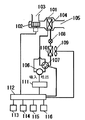
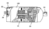
電動圧縮機を搭載した車両用空調装置について図面を参照して説明する。図4において、送風ダクト101は、室内送風ファン102の作用により空気導入口103から空気を吸い込み、室内熱交換器104で熱交換した空気を空気吹き出し口105から車室内に吹き出す。送風ダクト101内にある室内熱交換器104は、センサレスDCブラシレスモータを駆動源とする電動圧縮機106、冷媒の流れを切替えて冷房と暖房を選択するための四方切替弁107、絞り装置108および室外ファン109の作用で車室外空気と熱交換する室外熱交換器110とともに冷凍サイクルを構成している。
A vehicle air conditioner equipped with an electric compressor will be described with reference to the drawings. In FIG. 4, the
そして、電動圧縮機106の駆動源であるセンサレスDCブラシレスモータ(図示せず)を運転するインバータ装置111は、室内送風ファン102、四方切替弁107、および室外送風ファン109とともに、エアコンコントローラ112により動作が制御されている。
An
また、エアコンコントローラ112には、室内送風ファン102のON/OFF及び強弱を設定する室内送風ファンスイッチ113、冷房又は暖房又は運転OFFを選択するエアコンスイッチ114、温度調節スイッチ115等のスイッチ類および車両コントローラ(図示せず)との通信を行うための通信装置116が接続されている。
Further, the
図5に、上記電動圧縮機106の一例として、センサレスDCブラシレスモータを備えた電動圧縮機を示す。
FIG. 5 shows an electric compressor provided with a sensorless DC brushless motor as an example of the
同図において、金属製筐体32の中に圧縮機構部28(この例ではスクロール機構)、モータ31等が設置されている。冷媒は、吸入口33から吸入され、圧縮機構部28がモータ31で駆動されることにより圧縮される。この圧縮された冷媒は、金属製筐体32内においてモータ31を通過し、その際にモータ31の冷却を行い、吐出口34より吐出される。内部でモータ31の巻き線に接続されているターミナル39は、図4のインバータ装置111に接続されている。
In the figure, a compression mechanism 28 (a scroll mechanism in this example), a
このように、圧縮された高圧冷媒によりモータ31が冷却される電動圧縮機は、高圧型と称される。一方、冷媒の流れを逆にして、低圧冷媒によりモータ31が冷却される電動圧縮機は、低圧型と称される。
Thus, the electric compressor in which the
次に、インバータ装置111の冷却について説明する。インバータ装置111には、直流電圧をスイッチングすることにより、交流電流をモータ31へ出力するインバータ回路が備えられており、主としてこのインバータ回路から発生する熱を放熱する手段が、電子部品の保護のため、また、制御回路、電流センサなどの誤作動防止のために必要になる。そのため、空冷、水冷の放熱手段が用いられる(例えば、特許文献1参照)。
Next, cooling of the
特許文献1においては、インバータの駆動出力部はプリント基板の下に配置され、ヒートシンクに密着して、その消費電力による熱はヒートシンクに放熱される。ヒートシンクは水冷式であり、ホースを通して冷却水がポンプにより注入され冷却される技術が開示されている。
In
然しながらこのような冷却方法において、水冷においては、水を循環させる装置、放熱させる熱交換器などが必要となり、サイズ、重量ともに大幅にアップしてしまう。また、空冷においては、さらに大きな空冷ヒートシンクが必要となり、空調装置全体として、サイズ、重量ともに大幅にアップしてしまう。 However, in such a cooling method, in water cooling, a device for circulating water, a heat exchanger for radiating heat, and the like are required, and the size and weight are significantly increased. Further, in air cooling, a larger air cooling heat sink is required, and the size and weight of the entire air conditioner are significantly increased.
そこで、圧縮機に吸入される低圧冷媒により冷却し、サイズ、重量を低減する方法が考えられている(例えば、特許文献2参照)。 Thus, a method of reducing the size and weight by cooling with a low-pressure refrigerant sucked into the compressor has been considered (for example, see Patent Document 2).
特許文献2においては、インバーターの放熱部が圧縮機に接続した冷媒吸入管に冷却可能に接触するように、圧縮機と冷媒吸入管とインバーターとを適切に配置する技術が開示されている。
インバータ装置を冷却する手段として、上記低圧冷媒により冷却する方法においては、次の問題がある。 As a means for cooling the inverter device, the method of cooling with the low-pressure refrigerant has the following problems.
高圧型の電動圧縮機の場合、金属製筐体内の多くが高圧となるため、金属製筐体全体が高温となり、吸入口に接続されているンバータ装置冷却用の低圧冷媒管にも熱が伝わり温度が上昇してしまう。また、搭載されているインバータ装置が金属製筐体から加熱されやすくなる。このため、インバータ装置が充分に冷却されにくい。 In the case of a high-pressure type electric compressor, most of the metal casing has a high pressure, so the entire metal casing becomes hot and heat is also transmitted to the low-pressure refrigerant pipe for cooling the inverter device connected to the suction port. The temperature will rise. Further, the mounted inverter device is easily heated from the metal casing. For this reason, it is difficult for the inverter device to be sufficiently cooled.
一方、低圧型の電動圧縮機の場合、金属製筐体内の多くが低圧となるため上記問題は生じないが、低圧冷媒により、インバータ装置の冷却に加えモータも冷却する必要があるため、低圧冷媒が加熱され、圧縮機の効率低下の要因となる。 On the other hand, in the case of a low-pressure type electric compressor, the above-mentioned problem does not occur because most of the metal casing has a low pressure, but the low-pressure refrigerant needs to cool the motor in addition to the cooling of the inverter device. Is heated, causing a reduction in the efficiency of the compressor.
従来は上記のような課題を有していた。 Conventionally, it has the above-mentioned problems.
本発明はこのような従来の課題を解決するものであり、電動圧縮機の高い効率とインバータ装置の冷却とを両立させるインバータ装置一体型電動圧縮機を提供することを目的とする。 This invention solves such a conventional subject, and it aims at providing the inverter apparatus integrated electric compressor which makes the high efficiency of an electric compressor compatible with cooling of an inverter apparatus.
上記課題を解決するために本発明は、モータと、インバータ装置とを搭載し、圧縮機に吸入される低圧冷媒により吸入通路を介してインバータ装置を冷却する高圧型のインバータ装置一体型電動圧縮機において、吸入通路は断熱性を有する冷媒通路を介して圧縮機の吸入口に接続されるものである。 In order to solve the above-mentioned problems, the present invention is equipped with a motor and an inverter device, and a high-pressure inverter device-integrated electric compressor that cools the inverter device through a suction passage by a low-pressure refrigerant sucked into the compressor. The suction passage is connected to the suction port of the compressor through a refrigerant passage having heat insulation properties.
上記構成によって、高温となる金属製筐体からインバータを冷却する部分の低圧冷媒配管に熱が伝わることを防止し、インバータ装置が十分冷却されるようにするものである。 With the above configuration, heat is prevented from being transferred from the metal casing that is at a high temperature to the low-pressure refrigerant pipe that cools the inverter, and the inverter device is sufficiently cooled.
本発明のインバータ装置一体型電動圧縮機は、電動圧縮機の高い効率とインバータ装置冷却との両立が可能という効果を奏する。 The inverter device-integrated electric compressor of the present invention has an effect that both high efficiency of the electric compressor and cooling of the inverter device are possible.
第1の発明は、モータと、インバータ装置とを搭載し、圧縮機に吸入される低圧冷媒により吸入通路を介してインバータ装置を冷却する高圧型のインバータ装置一体型電動圧縮機において、吸入通路は断熱性を有した冷媒通路を介して圧縮機の吸入口に接続されるものである。これにより、高温となる金属製筐体から低圧冷媒通路に熱が伝わるこがを防止でき、インバータ装置を十分冷却できる。その結果、高圧型電動圧縮機の高い効率とインバータ装置冷却との両立が可能となる。 1st invention mounts a motor and an inverter apparatus, and the high-pressure type inverter apparatus integrated electric compressor which cools an inverter apparatus via a suction passage with the low-pressure refrigerant sucked into a compressor, a suction passage is It is connected to the suction port of the compressor via a refrigerant passage having heat insulation properties. Thereby, it can prevent that heat transfers from the metal housing | casing which becomes high temperature to a low voltage | pressure refrigerant path, and can fully cool an inverter apparatus. As a result, it is possible to achieve both high efficiency of the high-pressure electric compressor and inverter device cooling.
第2の発明は、第1の発明において、インバータ装置の被冷却部と前記金属製筐体との間に断熱材もしくは断熱空間を設けるもので、電動圧縮機からインバータ装置への熱伝導を防止し、インバータ装置の冷却を確実にできる。 According to a second invention, in the first invention, a heat insulating material or a heat insulating space is provided between the cooled part of the inverter device and the metal casing, and heat conduction from the electric compressor to the inverter device is prevented. Thus, the inverter device can be reliably cooled.
第3の発明は、第1乃至第2の発明において、車両用に適用するものである。車両においては、走行性能確保のため省エネが求められる。よって、本発明のインバータ装置一体型電動圧縮機は、効率が高く小型軽量であり車両用として好適である。 The third invention is applied to the vehicle in the first or second invention. Vehicles are required to save energy to ensure running performance. Therefore, the inverter apparatus-integrated electric compressor of the present invention is highly efficient, small and light, and suitable for vehicles.
以下本発明の実施の形態について図面を参照して説明する。なお、本実施の形態によって本発明が限定されるものではない。 Embodiments of the present invention will be described below with reference to the drawings. Note that the present invention is not limited to the embodiment.
(実施の形態1)
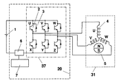
図1は、本発明の実施の形態1に係るインバータ装置一体型電動圧縮機の電気回路図である。図1において、圧縮機のモータ31は、直流電源1によりインバータ装置20を通して駆動される。インバータ装置20は、インバータ回路37、電流センサ6、制御回路7等から構成される。
(Embodiment 1)
1 is an electric circuit diagram of an inverter-integrated electric compressor according to
制御回路7は、電流センサ6からの電流を演算してモータ31の磁石回転子5の位置検出を行い、エアコンコントローラ(図示せず)からの回転数指令信号等に基づいてインバータ回路37のスイッチング素子2を制御する。そして、直流電源1からの直流電流を正弦波状の交流電流に変換し、インバータ回路37より、固定子巻線4と磁石回転子5から成る(センサレスDCブラシレス)モータ31へ出力する。ダイオード3は、固定子巻線4からの電流の還流ルートとなる。ここで、インバータ装置20の主たる発熱源は、直流電流を正弦波状の交流電流に変換し、モータ31へ出力するスイッチング素子2及びダイオード3から構成されるインバータ回路37である。
The
空調装置の構成に関しては、前述した図4において、インバータ装置111、電動圧縮機106が、本発明のインバータ装置一体型電動圧縮機に置きかわるのみで基本的に同じである。
The configuration of the air conditioner is basically the same as in FIG. 4 described above, except that the
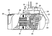
図2は、本実施の形態に係るインバータ装置一体型電動圧縮機の一部切り欠き断面図であり、インバータ装置20を電動圧縮機40の上に設置したインバータ装置一体型電動圧縮機を示す。金属製筐体32の中に圧縮機構部28、モータ31等が設置されている。冷媒は、吸入部22から、吸入管38、断熱性のあるゴム管21、吸入口33を介して、モータ31で駆動される圧縮機構部28(この例ではスクロール)により吸入され、圧縮される。この圧縮された冷媒は一旦金属製筐体32に排出され、モータ31を通過する際にモータ31を冷却して吐出口34より吐出される。
FIG. 2 is a partially cutaway sectional view of the inverter apparatus-integrated electric compressor according to the present embodiment, showing the inverter apparatus-integrated electric compressor in which the
インバータ装置20は電動圧縮機40に取り付けられるように、ケース30を使用し、金属製筐体32の上に設置されている。金属製筐体32の内部でモータ31の固定子巻線4に接続されているターミナル39は、、ケース30の内部でインバータ回路部37に接続される。インバータ装置20は、ハーネス固定部35で固定されたハーネス36により、直流電源1、エアコンコントローラなどへ接続される。
The
そして、吸入通路38がインバータ装置20の上に接して固定される。これにより、インバータ装置20の主たる発熱源となるインバータ回路部37は、吸入通路38を介して低圧冷媒により冷却される。
The
しかし、電動圧縮機40は高圧型であり、圧縮機構部28からの高圧冷媒が流れる経路、モータ31部など多くの部分が高温となる。そのため、伝熱により吸入口33も、伝熱により温度が上昇する。よって、この吸入口33に、吸入通路38を接続してインバータ回路部37を冷却するようにすると、吸入通路38も伝熱により温度上昇するため、インバータ回路部37を充分冷却することが困難になる。
However, the
そこで、本発明においては、吸入口33と吸入通路38との間の冷媒通路を、断熱性のあるゴムにより構成されたゴム配管21により構成した。これにより、吸入通路38が伝熱により温度上昇することはなく、インバータ回路部37を充分冷却することができる。吸入通路は扁平など形は問わない。ゴム配管に代わり、樹脂等でも良く、金属ならば熱伝導率の低いステンレスなどでも良い。
Therefore, in the present invention, the refrigerant passage between the
吸入冷媒は、モータ31の冷却には用いずモータ31による加熱はないので、圧縮の効率を高く維持できる。
The suction refrigerant is not used for cooling the
インバータ装置20は電動圧縮機40の上に設置されているが、インバータ回路部37と金属製筐体32との間に断熱空間24を設け、インバータ回路部37が高温の電動圧縮機40から加熱されるのを防止している。また、ケース30下側の材料をステンレスとして、断熱材の効果を持たせても良い。
Although the
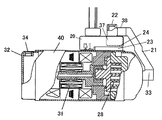
図3に、本実施の形態に係る、他の例のインバータ装置一体型電動圧縮機を示す。図2の例に比較し、インバータ装置20と電動圧縮機40の金属製筐体32との間に、断熱材23を追加している。材料としては、ゴム、他の樹脂、ステンレスなどであれば良い。また、断熱材23に代わり、空気、真空などの断熱空間を内部に設けた構造体を配置しても良い。
FIG. 3 shows another example of an inverter-integrated electric compressor according to the present embodiment. Compared to the example of FIG. 2, a
尚、上記冷却では、インバータ回路部37が結露しないように、インバータ回路部37は吸入配通路38の下方に配置され、インバータ回路部37の周囲温度も下げて温度差が小さくなるようにしている。吸入通路38による冷気が、ケース30内で下降対流するのでケース30内を効率的に冷却できる。よって、インバータ回路部37以外の電流センサ6、制御部7なども冷却され、インバータ装置20の信頼性を確保できる。
In the cooling, the
以上のように、本発明にかかるインバータ装置一体型電動圧縮機は、効率が高く、インバータ装置用の冷却装置を別途準備する必要はないので、船舶、航空機等の用途にも適用できる。 As described above, the inverter device-integrated electric compressor according to the present invention has high efficiency and does not require a separate cooling device for the inverter device, and therefore can be applied to applications such as ships and aircrafts.
20 インバータ装置
21 ゴム配管
23 樹脂断熱材
24 断熱空間
28 圧縮機構部
31 モータ
32 金属製筐体
33 吸入口
37 インバータ回路
38 吸入通路
40 電動圧縮機
DESCRIPTION OF
Claims (3)
Priority Applications (1)
| Application Number | Priority Date | Filing Date | Title |
|---|---|---|---|
| JP2004214056A JP2006037726A (en) | 2004-07-22 | 2004-07-22 | Inverter unit integrated electric compressor |
Applications Claiming Priority (1)
| Application Number | Priority Date | Filing Date | Title |
|---|---|---|---|
| JP2004214056A JP2006037726A (en) | 2004-07-22 | 2004-07-22 | Inverter unit integrated electric compressor |
Publications (1)
| Publication Number | Publication Date |
|---|---|
| JP2006037726A true JP2006037726A (en) | 2006-02-09 |
Family
ID=35902990
Family Applications (1)
| Application Number | Title | Priority Date | Filing Date |
|---|---|---|---|
| JP2004214056A Pending JP2006037726A (en) | 2004-07-22 | 2004-07-22 | Inverter unit integrated electric compressor |
Country Status (1)
| Country | Link |
|---|---|
| JP (1) | JP2006037726A (en) |
Cited By (6)
| Publication number | Priority date | Publication date | Assignee | Title |
|---|---|---|---|---|
| WO2008033096A1 (en) * | 2006-09-12 | 2008-03-20 | Panasonic Corporation | A compressor structure for a refrigeration system |
| WO2010016695A3 (en) * | 2008-08-06 | 2010-05-27 | 두원공과대학교 | Method for controlling inverter-integrated electric compressor for vehicle air-conditioning system |
| JP2011247215A (en) * | 2010-05-28 | 2011-12-08 | Denso Corp | Electric compressor |
| US8303270B2 (en) | 2007-12-18 | 2012-11-06 | Kabushiki Kaisha Toyota Jidoshokki | Motor-driven compressor |
| WO2016121382A1 (en) * | 2015-01-29 | 2016-08-04 | 株式会社デンソー | Electric compressor and electronic component |
| JP2019143501A (en) * | 2018-02-16 | 2019-08-29 | パナソニックIpマネジメント株式会社 | Inverter integrated type electric compressor |
-
2004
- 2004-07-22 JP JP2004214056A patent/JP2006037726A/en active Pending
Cited By (8)
| Publication number | Priority date | Publication date | Assignee | Title |
|---|---|---|---|---|
| WO2008033096A1 (en) * | 2006-09-12 | 2008-03-20 | Panasonic Corporation | A compressor structure for a refrigeration system |
| US8303270B2 (en) | 2007-12-18 | 2012-11-06 | Kabushiki Kaisha Toyota Jidoshokki | Motor-driven compressor |
| WO2010016695A3 (en) * | 2008-08-06 | 2010-05-27 | 두원공과대학교 | Method for controlling inverter-integrated electric compressor for vehicle air-conditioning system |
| CN102123880A (en) * | 2008-08-06 | 2011-07-13 | (学)斗源学院 | Method for controlling inverter-integrated electric compressor for vehicle air-conditioning system |
| JP2011247215A (en) * | 2010-05-28 | 2011-12-08 | Denso Corp | Electric compressor |
| WO2016121382A1 (en) * | 2015-01-29 | 2016-08-04 | 株式会社デンソー | Electric compressor and electronic component |
| JP2016142135A (en) * | 2015-01-29 | 2016-08-08 | 株式会社デンソー | Electric compressor and electronic parts |
| JP2019143501A (en) * | 2018-02-16 | 2019-08-29 | パナソニックIpマネジメント株式会社 | Inverter integrated type electric compressor |
Similar Documents
| Publication | Publication Date | Title |
|---|---|---|
| JP4200850B2 (en) | Electric compressor | |
| CN102016432B (en) | Air conditioner | |
| JP4718862B2 (en) | Electric compressor | |
| CN204730358U (en) | The off-premises station of air conditioner | |
| JP5173877B2 (en) | Power conversion device, motor with built-in drive circuit, and ventilation fan, air conditioner indoor unit, air conditioner, pump, and water heater equipped with the pump | |
| JP5842905B2 (en) | Refrigeration equipment | |
| JP2009055781A (en) | Motor drive control device, air conditioner, ventilation fan and heat pump type water heater | |
| JP2009264699A (en) | Heat pump device | |
| US20100218549A1 (en) | Refrigeration system | |
| JP2009299957A (en) | Air conditioner | |
| JP2012120348A (en) | Inverter cooling device | |
| JP2014114982A (en) | Compressor unit and refrigerating cycle device | |
| JP2019158254A (en) | Air conditioner | |
| CN104999890A (en) | Motor and battery temperature integration control system of electric automobile | |
| JP2013137132A (en) | Air conditioning device | |
| JP2019163878A (en) | Outdoor machine of air conditioner | |
| JP2004271167A (en) | Air conditioner | |
| JP2006037726A (en) | Inverter unit integrated electric compressor | |
| JP2004293554A (en) | Inverter integrated electric compressor | |
| JP2008175067A (en) | Electric compressor | |
| JP2007064542A (en) | Refrigeration apparatus and inverter apparatus used therefor | |
| CN104620485B (en) | The convertor device of air conditioner | |
| JP2010063200A (en) | Motor with built-in driving circuit, air conditioner equipped with it, ventilating fan, and heat pump type water heater | |
| JP2006125302A (en) | Oil-free screw compressor | |
| JP4164554B2 (en) | Refrigeration apparatus and inverter apparatus used therefor |