JP2006036498A - Folding/insertion device - Google Patents
Folding/insertion device Download PDFInfo
- Publication number
- JP2006036498A JP2006036498A JP2004221083A JP2004221083A JP2006036498A JP 2006036498 A JP2006036498 A JP 2006036498A JP 2004221083 A JP2004221083 A JP 2004221083A JP 2004221083 A JP2004221083 A JP 2004221083A JP 2006036498 A JP2006036498 A JP 2006036498A
- Authority
- JP
- Japan
- Prior art keywords
- continuous paper
- folding
- paper
- roller
- protruding
- Prior art date
- Legal status (The legal status is an assumption and is not a legal conclusion. Google has not performed a legal analysis and makes no representation as to the accuracy of the status listed.)
- Pending
Links
- 230000037431 insertion Effects 0.000 title abstract 6
- 238000003780 insertion Methods 0.000 title abstract 6
- 230000007246 mechanism Effects 0.000 claims abstract description 50
- 230000032258 transport Effects 0.000 description 10
- 230000007723 transport mechanism Effects 0.000 description 6
- 230000001154 acute effect Effects 0.000 description 3
- 239000000853 adhesive Substances 0.000 description 3
- 230000001070 adhesive effect Effects 0.000 description 2
- 238000005452 bending Methods 0.000 description 1
- 230000008878 coupling Effects 0.000 description 1
- 238000010168 coupling process Methods 0.000 description 1
- 238000005859 coupling reaction Methods 0.000 description 1
- 238000006073 displacement reaction Methods 0.000 description 1
- 239000002184 metal Substances 0.000 description 1
- 238000009958 sewing Methods 0.000 description 1
Images
Landscapes
- Folding Of Thin Sheet-Like Materials, Special Discharging Devices, And Others (AREA)
Abstract
Description
本発明は、連続用紙の搬送方向に沿って折り込みを形成する折り込み装置に関するものであり、より詳しくは、薄手の用紙や、ミシン目の少ない用紙に対しても正確に折り込みを形成することのできる折り込み装置に関するものである。 The present invention relates to a folding device that forms a fold along the conveyance direction of continuous paper. More specifically, the invention can accurately form a fold even on a thin paper or a paper with few perforations. The present invention relates to a folding device.
近年のハガキなどでは、三つ折りされた見開きページを密着させた折り込みのハガキなどが存在する。このような折り込みハガキは、特殊な接着剤を用いて見開きページを密着させるようにしたもので、一度そのページを開けると、再度そのページを閉じ込めることのできないようにしたものである。 In recent postcards and the like, there are folded postcards in which spread pages that are folded in three are brought into close contact with each other. Such a folded postcard is such that a spread page is brought into close contact with a special adhesive, and once the page is opened, the page cannot be confined again.
ところで、このようなハガキは、一般に、次のような装置によって生成される。 By the way, such a postcard is generally generated by the following apparatus.
一般に、このようなハガキ生成装置は、連続用紙の搬送方向に沿って折り込みを形成する折り込み機構と、この折り込まれた連続用紙の裁断と圧着とを行う処理装置本体とを設けて構成される。そして、このような装置を用いて折り込みのハガキを生成する場合、まず、載置台の上に接着剤を有する特殊な連続用紙を載置し、その用紙を蛇行させるように上側及び下側のローラを通し、折り込み機構に導く。この折り込み機構としては、下記の特許文献1に記載されるようなものなどが知られている。この特許文献1の折り込み機構は、球状の先端部分を有する複数の突出杆を交互に対向させて配置させるようにしたものであり、その突出杆を連続用紙に押圧させてZ字状に折り込めるようにしたものである。そして、このように折り込まれた連続用紙を、その下流側に設けられたローラに挟み込み、その後、定型のサイズに裁断して圧着ローラで圧着するようにしている。
ところで、近年、このようなハガキなどでは、薄手の用紙や、折り込み部分にミシン目の少ない用紙、例えば、ミシン目である破断部分と非破断部分の長さが一対一となっている用紙などが使用されるようになってきている。 By the way, in recent years, such postcards include thin paper, paper with few perforations in the folded portion, for example, paper in which the length of the perforated breakage and the non-breakage is one to one. It is becoming used.
しかしながら、このような薄手の用紙やミシン目の少ない用紙が使用された場合、従来の折り込み機構では、正確に折り込むことができない。すなわち、従来の折り込み機構では、突出杆の先端部分を球状としているため、薄手の用紙やミシン目を多く設けていない用紙では、腰が弱く、また、ミシン目の存在する部分と他の部分との区別ないため、他の部分を折り込んでしまう可能性がある。これを防止すべく、突出杆の先端部分を尖らせるようにすることも可能であるが、このようにすると、今度は、薄手の用紙を破いてしまう可能性がある。 However, when such thin paper or paper with few perforations is used, the conventional folding mechanism cannot be folded correctly. That is, in the conventional folding mechanism, since the tip end portion of the protruding ridge is spherical, a thin sheet or a sheet not provided with many perforations is weak, and the perforated part and other parts Therefore, there is a possibility that other parts will be folded. In order to prevent this, it is possible to sharpen the tip of the protruding ridge, but if this is done, there is a possibility that the thin paper will be torn.
そこで、本発明は上記課題に着目してなされたもので、薄手の用紙やミシン目の少ない用紙であっても正確に折り込むことができるような折り込み装置を提供することを目的とするものである。 Accordingly, the present invention has been made paying attention to the above problems, and an object of the present invention is to provide a folding device capable of accurately folding even a thin sheet or a sheet with few perforations. .
本発明は、上記課題を解決するため、連続用紙の搬送方向に沿って折り込みを形成する折り込み装置において、連続用紙の紙面側へ向かって突出する突出杆と、当該突出杆の先端に設けられた山型ローラと、当該山型ローラの対向する位置に設けられる受け部材とを具備するようにしたものである。 In order to solve the above-described problem, the present invention provides a folding device that forms a fold along the conveying direction of continuous paper, and is provided with a protruding hook that protrudes toward the paper surface side of the continuous paper, and a tip of the protruding hook. A mountain-shaped roller and a receiving member provided at a position facing the mountain-shaped roller are provided.
このように構成すれば、山型ローラの尖状部分でミシン目を集中的に押圧することができ、連続用紙のミシン目の部分を鋭角に折り込むことができるようになる。しかも、山型ローラが連続用紙に沿って回転するため、薄手の用紙が使用された場合であっても、その用紙を破いてしまうようなことがなくなる。 If comprised in this way, a perforation can be intensively pressed with the pointed part of a mountain-shaped roller, and the perforation part of continuous paper can be folded at an acute angle. In addition, since the chevron roller rotates along the continuous paper, even if a thin paper is used, the paper is not torn.
また、この突出杆に対向する斜め位置に、連続用紙の紙面側へ向かって突出する第二の突出杆を設け、更に、この第二の突出杆の先端に、回転軸を傾けたローラを設けるようにする。 In addition, a second protruding hook that protrudes toward the paper surface side of the continuous sheet is provided at an oblique position facing the protruding hook, and a roller having a rotating shaft inclined is provided at the tip of the second protruding hook. Like that.
このように構成すれば、例えば、連続用紙を三つ折りするような場合、傾斜した第二の山型ローラによって用紙に折り込みを形成しながら閉じ込みを行うことができるようになる。 According to this configuration, for example, when a continuous sheet is folded in three, the sheet can be closed while the sheet is folded by the inclined second chevron roller.
更に、突出杆もしくは第二の突出杆を有する補助フレームの少なくとも一部に、連続用紙の搬送方向に対して傾斜する傾斜部を設けるようにする。 Further, at least a part of the auxiliary frame having the protruding ridge or the second protruding ridge is provided with an inclined portion that is inclined with respect to the conveying direction of the continuous paper.
このように構成すれば、折り込み装置を処理装置本体に対して斜めに配置する場合、その傾斜部によって補助フレームが処理装置本体に接触することがなくなり、より接近した位置に折り込み装置を配置することができるようになる。 With this configuration, when the folding device is disposed obliquely with respect to the processing device main body, the auxiliary frame does not contact the processing device main body due to the inclined portion, and the folding device is disposed at a closer position. Will be able to.
加えて、連続用紙の裁断と圧着を行う処理装置本体に対し、載置台を斜めに連結するための連結機構を設けるようにする。 In addition, a connection mechanism for connecting the mounting table obliquely to the processing apparatus main body for cutting and pressure-bonding continuous paper is provided.
このように構成すれば、処理装置本体に対して載置台を斜めに固定することができ、連続用紙が高速に引き出された場合であっても、その連続用紙の引き出しに伴って載置台がずれることがなくなる。これにより、載置台のずれに基づくジャムなどを防止することができるようになる。 If comprised in this way, a mounting base can be diagonally fixed with respect to a processing apparatus main body, and even if it is a case where a continuous paper is pulled out at high speed, a mounting base will shift | deviate with the withdrawal of the continuous paper. Nothing will happen. As a result, it is possible to prevent a jam or the like based on the displacement of the mounting table.
本発明は、連続用紙の搬送方向に沿って折り込みを形成する折り込み装置において、連続用紙の紙面側へ向かって突出する突出杆と、当該突出杆の先端に設けられた山型ローラと、当該山型ローラの対向する位置に設けられる受け部材とを具備してなる折り込み機構を設けるようにしたので、山型ローラの尖状部分でミシン目を集中的に押圧することができ、連続用紙のミシン目の部分を鋭角に折り込むことができるようになる。しかも、山型ローラが連続用紙に沿って回転するため、薄手の用紙が使用された場合であっても、その用紙を破いてしまうようなことがなくなる。 The present invention relates to a folding device that forms a fold along the conveyance direction of continuous paper, a protruding hook that protrudes toward the paper surface side of the continuous paper, a chevron roller provided at the tip of the protruding hook, and the peak. Since the folding mechanism comprising the receiving member provided at the position opposite to the mold roller is provided, the perforation can be intensively pressed by the pointed portion of the mountain roller, and the continuous sheet sewing machine The eye part can be folded at an acute angle. In addition, since the chevron roller rotates along the continuous paper, even if a thin paper is used, the paper is not torn.
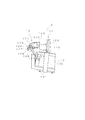
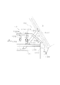
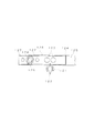
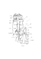
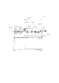
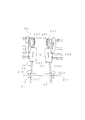
以下、本発明の一実施の形態について図面を参照して説明する。図1はこの折り込み装置2の外観斜視図、図2は折り込み機構12の近傍における平面図、図3は図2におけるA−A断面図である。また、図4はハガキ生成装置1による連続用紙5の折り込み状態を示す外観斜視図であり、図5は、処理装置本体3の側面概略図、図6は、処理装置本体3の前段部分を示す外観斜視図である。
Hereinafter, an embodiment of the present invention will be described with reference to the drawings. 1 is an external perspective view of the
この実施の形態におけるハガキ生成装置1は、図1もしくは図4に示すような連続用紙5に折り込みを形成するための折り込み装置2と、この折り込まれた連続用紙5に対して裁断と圧着を行うための処理装置本体3とを具備してなる。この折り込み装置2は、処理装置本体3に対して分離可能に設けられ、後述する連結機構13によって任意の角度で連結される。なお、この実施の形態においては、折り込み装置2と処理装置本体3によってハガキ生成装置1を構成するようにしているが、これとは別に、圧着されたハガキ50を区分けして集積する区分け装置を設けるようにしても良い。以下、本実施の形態について詳細に説明する。
The
このハガキ生成装置1を構成する折り込み装置2は、図4に示すようなジグザグ状の連続用紙5を載置する載置台10と、この載置台10に載置された連続用紙5の一端を引き出す引き出し機構11と、この引き出し機構11によって引き出された連続用紙5を折り込む折り込み機構12とを具備してなる。
The
この折り込み装置2の載置台10は、連続用紙5を載置する平面部100を設けてなり、その下方に設けられたキャスター101によって移動可能に構成される。そして、この載置台10の両側には、それぞれ対をなす第一の支柱102及び第二の支柱103を設け、この第一の支柱102及び第二の支柱103に引き出し機構11と折り込み機構12を設けている。
The mounting table 10 of the
この引き出し機構11は、第一の支柱102の上端に設けられる引き出し部材110と、第二の支柱103の下方に設けられた誘導部材111を設けている。この引き出し部材110と誘導部材111とは、ともに水平な回転ローラによって構成されるもので、ジグザグ状に折り畳まれた連続用紙5を上側に引き出した後、誘導ローラまで引き下げて連続用紙5のジグザグ状のクセを取り除けるようにしたものである。
The
また、この第二の支柱103の上方には、連続用紙5に折り込みを形成する折り込み機構12が設けられる。この折り込み機構12の詳細を、図1から図3に示す。この折り込み機構12は、水平状に設けられた第一の補助フレーム120及び第二の補助フレーム124設け、この第一の補助フレーム120及び第二の補助フレーム124に第一の突出杆121や第二の突出杆128、受け部材123などを設ける。この折り込み機構12の構成について詳細に説明する。
Further, a
第一の補助フレーム120は、第二の支柱103の内側から突出するように設けられ、また、第二の補助フレーム124は、第二の支柱103の外側に向かって傾斜部125及び対向部126を設けて構成される。この傾斜部125は、折り込み装置2を処理装置本体3に斜めに連結した場合に、第二の補助フレーム124が処理装置本体3に接触しないように設けられる。
The first
この第一の補助フレーム120の先端部分には、山型ローラ122を有する第一の突出杆121が設けら、更に、これに対向する位置に受け部材123が設けられる。この受け部材123は、先端を球形とした棒状のもので、この2本の受け部材123と山型ローラ122との間に連続用紙5のミシン目部分を挟み込み、山型ローラ122で押圧することによってそのミシン目部分に折り込みを形成できるようにしたものである。なお、この受け部材123については、棒状の構成に限らず、山型ローラ122に対応するV字状の凹部を有するローラによって構成しても良い。
A
更に、この第一の突出杆121に対向する第二の補助フレーム124の斜め位置には第二の突出杆128が設けられる。この第二の突出杆128は、連続用紙5をZ字状に折り込むべく第二の補助フレーム124から突出させるようにしたもので、第一の突出杆121と同様に、その先端部分に連続用紙5のミシン目を押圧しながら回転する山型ローラ129を設ける。この第二の突出杆128の山型ローラ129は、連続用紙5に折り込みを形成しながらその見開きページを閉じ込めるようにすべく、その回転軸を傾斜させるようにしている。具体的には、この第二の突出杆128及び山型ローラ129は、第一の突出杆121と同じ構成を有し、図3に示すように、その第一の突出杆121を回転させた状態で第二の補助フレーム124に取り付けるようにしている。これにより、山型ローラ129が回転することによって折り込みと同時に連続用紙5を閉じ込むことができるようになる。この第二の突出杆128は、その基端部に設けられたC型金具128a(図2、図4参照)の締め付け状態を緩めることによって、その傾斜角度や突出長さを任意に変更できるようにしている。また、この第二の突出杆128は、その取り付け位置を移動できるように構成されている。この取り付け位置の移動は、第二の補助フレーム124の先端近傍に設けられた複数の取付孔127を適宜選択し、この取付孔127に第二の突出杆128をネジ止めすることによって行われる。これにより、幅の寸法の異なる連続用紙5に対応することができる。
Further, a second
そして、このように構成された折り込み装置2を使用する場合、図2に示すような連結機構13によって処理装置本体3に所定の角度をなして固定される。
And when using the
この連結機構13は、処理装置本体3(図2では破線で示す)の角部近傍に対して回転可能に軸支される軸部130と、任意の角度で処理装置本体3に連結固定するための連結杆131とを設けて構成される。折り込み装置2を固定する場合、軸部130を中心に折り込み装置2を最適な角度で配置するとともに、その状態で連結杆131を処理装置本体3に連結して固定する。この連結杆131は、一方を折り込み装置2に回転可能に軸支され、他端側を処理装置本体3の下面に設けられた長孔132にネジ止めして固定される。そして、連結時においては、処理装置本体3の長孔132に連結杆131の一端を固定することによって最適な角度で連結できるようにしている。このようにして折り込み装置2を処理装置本体3に連結することにより、次に示すようにして連続用紙5を閉じ込んだ状態で処理装置本体3側に搬送することができる。
The
まず、図4に示すように、連続用紙5の一端側をA点、第一の突出杆121に当接するミシン目部分をB点、第二の突出杆128に当接するミシン目部分をC点、連続用紙5の他端側をD点とした場合、折り込み機構12によって、C点がA点に一致し、また、D点がB点に一致するように折り込まれる。通常、紙はその紙面の法線方向に対してのみ撓むことができるため、当初X1方向にしか撓むことのできなかった連続用紙5は、今度は角度を変えてX2方向にしか撓むことができなくなる。このとき、折り込み装置2を傾斜させた状態で処理装置本体3に連結すると、このX1方向からX2方向へスムーズに撓みの方向を変更させることができるようになる。これにより、無理なく連続用紙5を閉じ込んだ状態で処理装置本体3側に搬送することができるようになる。
First, as shown in FIG. 4, one end side of the
次に、この折り込み装置2に連結される側の処理装置本体3の構成について説明する。
Next, the structure of the processing apparatus
処理装置本体3は、図5に示すように、折り込まれた連続用紙5を挟み込む挟持ローラ20と、連続用紙5の両側部分に設けられた搬送孔51に嵌合して連続用紙5を搬送する搬送機構22と、この搬送機構22によって搬送された連続用紙5を縦方向及び横方向に裁断する裁断機構23と、この裁断機構23によって裁断された用紙を上下方向から圧着する圧着ローラ24とを具備してなる。
As shown in FIG. 5, the processing apparatus
この挟持ローラ20は、折り込み装置2によって折り込まれた連続用紙5を上下に挟み込んで完全に折り込めるようにしたものである。この挟持ローラ20の下流側には、連続用紙5の両側をガイドするためのガイド機構21が設けられ、搬送方向の変えた連続用紙5を強制的にガイド片210に沿って搬送しうるようにしている。このガイド機構21は、図6に示すように、左右二つのガイド片210と、このガイド片210をスライド可能に支持するためのバー211とを設けて構成されるもので、このガイド片210をスライドさせ、任意の位置で固定することによって連続用紙5の幅に対応できるようにしている。
The sandwiching
搬送機構22は、連続用紙5の両側に設けられた搬送孔51に嵌合して連続用紙5を搬送するもので、連続用紙5の搬送孔51に嵌合する嵌合突起220(図5参照)と、この嵌合突起220に嵌合された連続用紙5を上側から覆うカバー体211(図6参照)とを具備してなり、この嵌合突起220を搬送方向にスライド回転させることによって連続用紙5を搬送させる。このカバー体211は、側方の図示しないヒンジ機構を介して開閉可能に構成される。また、この嵌合突起220及びカバー体211は、その下方に設けられたスクリューネジ機構222によってその軸方向(連続用紙5の幅方向)にスライドできるように構成される。
The
裁断機構23は、連続用紙5の側辺に設けられた搬送孔51を裁断する縦方向裁断機構230と、連続用紙5を搬送方向と垂直な方向に裁断する横方向裁断機構233とを備えて構成される。このうち縦方向裁断機構230は、回転刃231と受刃232とを設けて構成されるもので、これらを回転させることによって連続用紙5の両側部分をミシン目に沿って裁断する。また、横方向裁断機構233は、用紙を搬送する2本の回転ローラ234の間に裁断刃235を設けてなるもので、下流側のローラを高速回転させることによって張力を付与し、その際、連続用紙5のミシン目に裁断刃235を当接させることによって裁断できるようにしたものである。
The
また、圧着ローラ24は、この裁断された用紙を上下方向から圧力を加えて見開きページを圧着できるようにしたもので、一次圧着ローラと二次圧着とによって用紙に所定の圧力を加え、接着剤を溶解させて圧着できるようにしたものである。
The
次に、このように構成された処理装置本体3を用いて連続用紙5から折り込みハガキ50を生成する場合の動作について説明する。
Next, an operation when the
まず、接着剤を塗布した特殊な連続用紙5から折り込みハガキ50を生成する場合、その連続用紙5を載置台10の上に載置し、その一端を手で引き出して、第一の支柱102の上側の引き出し部材110及び第二の支柱103の下側の誘導部材111を通す。そして、その先端部分を軽く搬送方向に沿って手で折り込み、その部分を折り込み機構12に通す。そして、このZ字状に折り込まれた状態の連続用紙5を処理装置本体3側の挟持ローラ20に挟み込み、ガイド機構21のガイド片210の幅を調整した上で、搬送機構22まで引き込む。この搬送機構22へ連続用紙5をセットする際は、まず、カバー体211を開放し、その内側の嵌合突起220に連続用紙5の搬送孔51を嵌合させる。そして、カバー体211を閉じる。
First, when the
この状態で処理装置本体3の電源をオンにすると、搬送機構22が駆動し、連続用紙5が搬送し始める。この搬送によって、連続用紙5は、順次折り込み機構12によって連続的にZ字状に折り込まれ、挟持ローラ20によって完全に折り込まれた後、縦方向裁断機構230によって両側の搬送孔51の存在する部分が縦長方向に裁断される。そして、今度は、速度差を有する回転ローラ234によって連続用紙5に張力を付与し、裁断刃235によって横方向に裁断する。そして、このようにして裁断されたハガキ50を圧着ローラ24側に搬送し、一次圧着と二次圧着を行って見開きのページを非可逆的に圧着する。
When the power of the processing apparatus
このように、上記実施の形態によれば、連続用紙5の搬送方向に沿って折り込みを形成する折り込み機構12を設けてなる連続用紙5の折り込み装置2において、この折り込み機構12を、連続用紙5の紙面側へ向かって突出する第一の突出杆121と、この第一の突出杆121の先端に設けられた山型ローラ122と、この山型ローラ122の対向する位置に設けられる受け部材123とを設けるようにしたので、山型ローラ122の尖状部分でミシン目を集中的に押圧することができ、連続用紙5のミシン目の部分を鋭角に折り込むことができるようになる。しかも、山型ローラ122が連続用紙5に沿って回転するため、薄手の用紙が使用された場合であっても、その用紙を破いてしまうようなことがなくなる。
As described above, according to the embodiment, in the
また、この第一の突出杆121に対向する斜め位置に、連続用紙5の紙面側へ向かって突出する第二の突出杆128を設け、第二の突出杆128の先端に、回転軸を傾けた山型ローラ129を設けるようにしたので、連続用紙5をZ字状に折り込むと同時に、見開きページを閉じ込むことができるようになる。
In addition, a
更に、第二の突出杆128を有する第二の補助フレーム124に、連続用紙5の搬送方向に対して傾きを有する傾斜部125を設けたので、折り込み装置2を処理装置本体3に対して斜めに配置した場合であっても、第二の補助フレーム124が処理装置本体3に接触するようなことがなくなり、より接近した位置に折り込み装置2を配置することができるようになる。
In addition, since the second
加えて、連続用紙5の裁断と圧着を行う処理装置本体3に対し、載置台10を斜めに連結するための連結機構13を設けるようにしたので、処理装置本体3に対して載置台10を傾斜させて固定することができ、連続用紙5が高速に引き出された場合であっても、その連続用紙5に引きずられて載置台10が移動してしまうということがなくなる。また、これに伴って、折り込み不良に基づくジャムなどを防止することができるようになる。
In addition, since the processing mechanism
なお、本発明は上記実施の形態に限定されることなく、種々の態様で実施することができる。 In addition, this invention is not limited to the said embodiment, It can implement in a various aspect.
例えば、上記実施の形態においては、連続用紙5からハガキ50を生成する場合について説明したが、これに限らず、他の用途の折り込み用紙を生成する場合についても適用することができる。
For example, in the above embodiment, the case where the
また、上記実施の形態では、第一の補助フレーム120側に第一の突出杆121を設け、また、傾斜部125を有する第二の補助フレーム124側に受け部材123と第二の突出杆128とを設けるようにしているが、これと逆の構成とするようにしても良い。すなわち、第二の補助フレーム124側に第一の突出杆121を設け、また、第一の補助フレーム120側に受け部材123や第二の突出杆128を設けるようにしても良い。
In the above embodiment, the first protruding
2・・・折り込み装置
5・・・連続用紙
13・・・連結機構
50・・・ハガキ
121・・・第一の突出杆
122・・・山型ローラ
123・・・受け部材
124・・・第二の補助フレーム
125・・・傾斜部
128・・・第二の突出杆
129・・・山型ローラ
130・・・軸部
131・・・連結杆
132・・・長孔
2 ... folding
Claims (4)
連続用紙の紙面側へ向かって突出する突出杆と、当該突出杆の先端に設けられた山型ローラと、当該山型ローラの対向する位置に設けられる受け部材とを具備してなる折り込み機構を設けたことを特徴とする折り込み装置。 In a folding device that forms a fold along the conveyance direction of continuous paper,
A folding mechanism comprising a protruding hook protruding toward the paper surface side of the continuous paper, a chevron roller provided at the tip of the protruding hook, and a receiving member provided at a position facing the chevron roller. A folding device characterized by being provided.
Priority Applications (1)
| Application Number | Priority Date | Filing Date | Title |
|---|---|---|---|
| JP2004221083A JP2006036498A (en) | 2004-07-29 | 2004-07-29 | Folding/insertion device |
Applications Claiming Priority (1)
| Application Number | Priority Date | Filing Date | Title |
|---|---|---|---|
| JP2004221083A JP2006036498A (en) | 2004-07-29 | 2004-07-29 | Folding/insertion device |
Publications (1)
| Publication Number | Publication Date |
|---|---|
| JP2006036498A true JP2006036498A (en) | 2006-02-09 |
Family
ID=35901898
Family Applications (1)
| Application Number | Title | Priority Date | Filing Date |
|---|---|---|---|
| JP2004221083A Pending JP2006036498A (en) | 2004-07-29 | 2004-07-29 | Folding/insertion device |
Country Status (1)
| Country | Link |
|---|---|
| JP (1) | JP2006036498A (en) |
Cited By (1)
| Publication number | Priority date | Publication date | Assignee | Title |
|---|---|---|---|---|
| JP5982529B1 (en) * | 2015-04-24 | 2016-08-31 | ユニ・チャーム株式会社 | Method and apparatus for manufacturing parts for absorbent articles |
-
2004
- 2004-07-29 JP JP2004221083A patent/JP2006036498A/en active Pending
Cited By (6)
| Publication number | Priority date | Publication date | Assignee | Title |
|---|---|---|---|---|
| JP5982529B1 (en) * | 2015-04-24 | 2016-08-31 | ユニ・チャーム株式会社 | Method and apparatus for manufacturing parts for absorbent articles |
| WO2016170909A1 (en) * | 2015-04-24 | 2016-10-27 | ユニ・チャーム株式会社 | Method and device for manufacturing component used in absorbent article |
| CN107405219A (en) * | 2015-04-24 | 2017-11-28 | 尤妮佳股份有限公司 | The method and apparatus for manufacturing the part of absorbent commodity |
| KR20170139502A (en) * | 2015-04-24 | 2017-12-19 | 유니챰 가부시키가이샤 | Method and apparatus for manufacturing parts for absorbent articles |
| CN107405219B (en) * | 2015-04-24 | 2020-10-30 | 尤妮佳股份有限公司 | Method and apparatus for making parts for absorbent articles |
| KR102511259B1 (en) | 2015-04-24 | 2023-03-16 | 유니챰 가부시키가이샤 | Method and Apparatus for Manufacturing Components for Absorbent Articles |
Similar Documents
| Publication | Publication Date | Title |
|---|---|---|
| EP1391405A3 (en) | Sheet material guiding mechanism, and sheet material feeding and conveying device provided with such mechanism, and recording apparatus | |
| EP3395578B1 (en) | Thermal printer and portable terminal | |
| JP2005329704A (en) | Label printer | |
| JP2006036498A (en) | Folding/insertion device | |
| JP3962584B2 (en) | Image forming apparatus | |
| JP2001080753A (en) | Paper feeding device | |
| US4516761A (en) | Motor driven continuous form folder | |
| EP0872776A3 (en) | Stalled sheet folding and flattening apparatus in an electrostatographic machine | |
| JP4316770B2 (en) | Film transfer tool | |
| JPH11301924A (en) | Device and method for folding sheet | |
| JP2009018357A (en) | Sheet puncher | |
| US7002612B2 (en) | Paper cutter and thermal printer | |
| JP2000016692A (en) | Single-sheet paper folding device | |
| JP4322832B2 (en) | To-be-processed material supply holder and recording apparatus, to-be-processed material supply switching method and recording method | |
| JP5083474B2 (en) | Line thermal printer | |
| JP2007030022A (en) | Solder feeding mechanism | |
| JPH11100151A (en) | Manual paper feeder | |
| CN213637891U (en) | image reading device | |
| JP3007298B2 (en) | Sheet feeder | |
| JP3377014B2 (en) | Paper transport device | |
| JP3134234U (en) | Roll paper holder | |
| JPS606557A (en) | paper feeding device | |
| JP2025502223A (en) | Conveying mechanism, cutting mechanism and tissue box | |
| JPH0328044Y2 (en) | ||
| JP5612789B1 (en) | Tape applicator |