JP2006029068A - Locking device for door - Google Patents
Locking device for door Download PDFInfo
- Publication number
- JP2006029068A JP2006029068A JP2005175216A JP2005175216A JP2006029068A JP 2006029068 A JP2006029068 A JP 2006029068A JP 2005175216 A JP2005175216 A JP 2005175216A JP 2005175216 A JP2005175216 A JP 2005175216A JP 2006029068 A JP2006029068 A JP 2006029068A
- Authority
- JP
- Japan
- Prior art keywords
- lock lever
- door
- fixed unit
- lock
- locking device
- Prior art date
- Legal status (The legal status is an assumption and is not a legal conclusion. Google has not performed a legal analysis and makes no representation as to the accuracy of the status listed.)
- Granted
Links
Images
Abstract
Description
本発明は地震などによって食器棚などの扉が勝手に開かないようにするための扉の施錠装置に関し、さらに詳しく言えば、扉を閉じたときに自動的に施錠する回転式扉の施錠装置に関するものである。 The present invention relates to a door locking device for preventing doors such as cupboards from being opened unnecessarily due to an earthquake or the like, and more particularly to a rotary door locking device that automatically locks when the door is closed. Is.
地震が発生した場合、食器棚やタンスなどの扉が振動によって勝手に開き収納物が室内に散乱することが懸念されている。とりわけ、食器棚に収納されている収納物の多くはガラス材や陶器製で落下の衝撃によって壊れやすいため、その破片によって二次的な被害を引き起こし兼ねない。 When an earthquake occurs, there is a concern that doors such as cupboards and chests will open without permission due to vibration and the stored items will be scattered indoors. In particular, many of the items stored in the cupboard are made of glass or ceramics and are easily broken by the impact of dropping, and the broken pieces may cause secondary damage.
このような扉の開きによって引き起こされる二次的な被害を防止するための防災用品が種々提案されているが、簡単な構成のものとしては、例えば特許文献1に記載されているように、両開き扉の各扉体に設けられた固定金具の間にボールチェーンを掛け渡して扉の開閉を防止する扉の開き止め金具がある。
Various disaster prevention products for preventing secondary damage caused by the opening of such doors have been proposed, but as a simple configuration, for example, as described in
また、例えば特許文献2には、振り子式の地震感知手段によって振動を感知してロック軸を自動的に作動させることにより扉が開かないようにした感震ロック具が提案されている。これによれば、日常生活には開閉に支障なく使用でき揺れを感知すると自動的に扉にロックを掛けるかけることができる。
For example,
しかしながら、いずれの装置にしても次のような問題がある。すなわち、特許文献1に記載の開き止め金具の場合は、常にボールチェーンを掛け渡してロックを掛けておく必要があり、開閉のたびにロックをいちいち外さなくてはならない。また、片手で操作することが難しいため操作性にも難がある。
However, any device has the following problems. In other words, in the case of the opening stopper described in
また、特許文献2に記載の感震ロック具は、地震感知手段に複雑な構成を必要とするためコストが高くなることは否めない。また、誤作動によってロックがかかってしまう場合も多く、そのたびにいちいちロックを解除するのは面倒である。そればかりでなく、地震の場合に確実に動作するかどうかという不安もある。
Moreover, since the seismic locking device described in
本発明は上述した問題を解決するためになされたものであって、その目的は、扉に対する取り付けを含めて操作が簡単であって、扉を閉めるたびに確実に自動ロックがかかるようにした扉の施錠装置を安価に提供することにある。 The present invention has been made to solve the above-described problems, and its purpose is to provide a door that is easy to operate, including attachment to the door, and that automatically locks whenever the door is closed. It is to provide a locking device at low cost.
上記目的を達成するため、本発明は以下に示すいくつかの特徴を備えている。まず、請求項1に記載の発明は、食器棚などに設けられている回転式の扉体を閉じたときに自動的に施錠する扉の施錠装置において、上記扉体の戸当たりを挟んで左右一対として対向的に配置される第1および第2の固定ユニットを含み、上記第1固定ユニットには、上記第2固定ユニットに対して進入・後退可能なロックレバーと、上記ロックレバーを上記第2固定ユニットに向かう進入方向に常時付勢するバネ手段と、上記ロックレバーを上記第2固定ユニット内に深く進入している施錠位置から上記バネ手段の付勢力に抗して解錠位置に後退させる操作ノブと、上記ロックレバーの動きを制御するロック制御手段とが設けられ、上記ロック制御手段は、上記ロックレバーを上記解錠位置から上記扉体が閉扉可能な状態で上記ロックレバーの先端側の一部分が上記第2固定ユニットの端縁に当接し得る待機位置に案内するとともに、上記待機位置で上記ロックレバーが上記第2固定ユニットと当接して後退させられると上記ロックレバーの上記待機位置から上記施錠位置への移動を可能とすることを特徴としている。
In order to achieve the above object, the present invention has the following features. First, the invention described in
請求項2に記載の発明は、上記請求項1において、上記ロック制御手段には、相対的に移動するラッチピンとラッチピンガイド部とが含まれ、上記ラッチピンガイド部には、上記ラッチピンを上記施錠位置から第1の上記解錠位置に向けて案内する往路側の第1ラッチガイド溝と、上記ラッチピンを上記解錠位置から上記待機位置に向けて案内する中間の第2ラッチガイド溝と、上記ラッチピンを上記待機位置から一旦第2の上記解錠位置に導いてから上記施錠位置に戻す復路側の第3ラッチガイド溝とが環状に形成されていることを特徴としている。 According to a second aspect of the present invention, in the first aspect, the lock control means includes a relatively moving latch pin and a latch pin guide portion, and the latch pin guide portion includes the latch pin. A first latch guide groove on the forward path that guides from the locked position toward the first unlocked position, and an intermediate second latch guide groove that guides the latch pin from the unlocked position toward the standby position; A third latch guide groove on the return path side that leads the latch pin from the standby position to the second unlocked position and then returns to the locked position is formed in an annular shape.
請求項3に記載の発明は、上記請求項2において、上記ロック制御手段には、少なくとも上記施錠位置と上記待機位置とにおいて上記ラッチピンのピン端部を目視可能とする透視孔が設けられていることを特徴としている。 According to a third aspect of the present invention, in the second aspect, the lock control means is provided with a see-through hole that allows the pin end portion of the latch pin to be seen at least at the locking position and the standby position. It is characterized by that.
請求項4に記載の発明は、上記請求項1ないし3のいずれか1項において、上記各固定ユニットはともに筒状に形成されたハウジングを備え、上記ロックレバーの先端および/または上記第2固定ユニットのハウジングの開口端縁には回転方向の力を上記ロックレバーに直線方向の力として与えるテーパー面が形成されていることを特徴としている。 According to a fourth aspect of the present invention, in any one of the first to third aspects, each of the fixing units includes a housing formed in a cylindrical shape, and the distal end of the lock lever and / or the second fixing unit. The opening edge of the housing of the unit is formed with a tapered surface that applies a rotational force as a linear force to the lock lever.
請求項5に記載の発明は、上記請求項1ないし4のいずれか1項において、上記ロックレバーと上記第2固定ユニットのハウジングとの間には、ガイドレールとガイド溝とからなるロックレバーガイド手段が設けられていることを特徴としている。 According to a fifth aspect of the present invention, in any one of the first to fourth aspects, the lock lever guide comprising a guide rail and a guide groove between the lock lever and the housing of the second fixed unit. Means is provided.
請求項6に記載の発明は、上記請求項1ないし5のいずれか1項において、上記各固定ユニットを上記扉体の戸当たりを挟んで左右一対として対向的に配置する際に、それらの間隔を規定するスペーサを備えていることを特徴としている。 A sixth aspect of the present invention is the method according to any one of the first to fifth aspects, wherein the fixing units are arranged to be opposed to each other as a pair on the left and right sides of the door unit. It is characterized by having a spacer that defines the above.
請求項7に記載の発明は、上記請求項1〜6において、上記ロックレバーには、上記扉体が強制的に開かれた際に、上記ロックレバーが上記第2固定ユニットから抜け出ることを防止するための脱落防止手段が設けられていることを特徴としている。 According to a seventh aspect of the present invention, in the first to sixth aspects, the lock lever prevents the lock lever from coming out of the second fixed unit when the door body is forcibly opened. It is characterized in that a drop-off preventing means is provided.
請求項8に記載の発明は、上記請求項7において、上記脱落防止手段は上記ロックレバーの上記扉体と対向する側の底面に幅方向に沿って形成された係止溝からなり、上記係止溝が上記第2固定ユニットの開口部に噛合することを特徴としている。 According to an eighth aspect of the present invention, in the seventh aspect, the drop-off prevention means comprises a locking groove formed along the width direction on the bottom surface of the lock lever facing the door body. A stop groove meshes with the opening of the second fixed unit.
請求項9に記載の発明は、上記請求項1〜8のいずれか1項において、上記各固定ユニットは、所定の固定手段を介して被取付面に取り付けられるベース板を有し、上記ベース板は上記各固定ユニットに対してスライド可能に取り付けられていることを特徴としている。 According to a ninth aspect of the present invention, in any one of the first to eighth aspects, each of the fixing units includes a base plate that is attached to a mounting surface via a predetermined fixing means, and the base plate Is characterized by being slidably attached to each of the fixed units.
請求項1に記載の発明によれば、操作ノブをスライドさせてロックレバーを解錠位置に戻して扉を開けたのち、操作ノブから手を離すとロック制御手段によりロックレバーが待機位置に案内されロックレバーの先端が第2固定ユニットの端縁に当接し得るように保持される。したがって、開けた扉を閉める際にロックレバーが第2固定ユニット(もしくは扉の戸当たり)により押し戻され、これによりロックレバーが待機位置から施錠位置に向けて飛び出し扉をロックする。このように、本発明によれば扉を閉めるたびに自動的に扉がロックされるためユーザーに安心感(信頼感)を与えることができる。しかも、構成が複雑な振動感知手段などを必要としないことから安価に提供できる。 According to the first aspect of the present invention, after the operation knob is slid to return the lock lever to the unlocked position and the door is opened, when the hand is released from the operation knob, the lock control means guides the lock lever to the standby position. The tip of the lock lever is held so that it can abut against the edge of the second fixed unit. Accordingly, when the opened door is closed, the lock lever is pushed back by the second fixing unit (or the door contact of the door), and the lock lever is then pushed out from the standby position toward the lock position to lock the door. Thus, according to the present invention, since the door is automatically locked every time the door is closed, a sense of security (reliability) can be given to the user. In addition, it can be provided at low cost because it does not require vibration sensing means having a complicated structure.
請求項2に記載の発明によれば、ロック制御手段がラッチピンとラッチガイド溝とよりなり、電気的な制御系を一切含まないとともに構成が複雑な振動感知手段なども必要としないことから安価に提供できる。 According to the second aspect of the present invention, the lock control means includes a latch pin and a latch guide groove, does not include any electrical control system, and does not require a vibration sensing means having a complicated configuration. Can be provided.
請求項3に記載の発明によれば、組立時にラッチピンの位置確認と動作チェックを行うことができるばかりでなく、簡単な故障の場合には修理も行うことができる。 According to the third aspect of the present invention, not only can the position and operation of the latch pin be checked during assembly, but also a repair can be performed in the case of a simple failure.
請求項4に記載の発明によれば、ロックレバーの先端および/または第2固定ユニットのハウジングの開口端縁に回転方向の力をロックレバーに直線方向の力として与えるテーパー面を設けたことにより、扉を閉じる際にロックレバーを確実に押し戻すことができる。 According to the fourth aspect of the present invention, by providing a tapered surface that applies a rotational force as a linear force to the lock lever at the tip of the lock lever and / or the opening edge of the housing of the second fixed unit. When the door is closed, the lock lever can be reliably pushed back.
請求項5に記載の発明によれば、ロックレバーと第2固定ユニットのハウジングとの間にガイドレールとガイド溝とからなるロックレバーガイド手段が設けられているため、ロック状態においてたとえ過大な負荷がかけられたとしてもロックが解除されたり破壊されるのを防ぐことができる。 According to the fifth aspect of the present invention, the lock lever guide means including the guide rail and the guide groove is provided between the lock lever and the housing of the second fixed unit. Even if it is applied, the lock can be prevented from being released or destroyed.
請求項6に記載の発明によれば、第1固定ユニットと第2固定ユニットの相対的な位置決めをするためのスペーサが付属されていることにより、取り付け作業が不得手なユーザーでも正確な位置に確実に取り付けることができる。 According to the sixth aspect of the present invention, since the spacer for positioning the first fixed unit and the second fixed unit is attached, even a user who is not good at the mounting operation can obtain an accurate position. Can be attached securely.
請求項7および8に記載の発明によれば、ロックレバーの一部に脱落防止手段としての係止溝を設けたことにより、強制的に扉体の開方向への力が加わっても、ロックレバーの係止溝が第2固定ユニットの開口縁に引っ掛かることにより、扉が開くことを防止することができる。 According to the seventh and eighth aspects of the present invention, the locking groove as the drop-off preventing means is provided in a part of the lock lever, so that even if a force in the opening direction of the door body is forcibly applied, the lock lever is locked. When the latching groove of the lever is hooked on the opening edge of the second fixed unit, the door can be prevented from opening.
請求項9に記載の発明によれば、固定ユニットに対してベース板がスライド可能に取り付けられていることにより、扉体が強制的に開かれたとしても、ベース板に対して固定ユニットがスライドして扉の開き量の一部を吸収することができる。 According to the ninth aspect of the present invention, since the base plate is slidably attached to the fixed unit, the fixed unit slides relative to the base plate even if the door body is forcibly opened. Then, a part of the opening amount of the door can be absorbed.
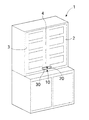
次に、図面を参照しながら本発明の実施形態について説明するが、本発明はこれに限定されるものではない。説明に用いる図面は図1ないし図10であるが、そのうち図1は本発明による扉の施錠装置を食器棚などの両開き式扉に使用した状態を示す斜視図で、図2は上記扉の施錠装置が解錠された状態を示す斜視図である。 Next, embodiments of the present invention will be described with reference to the drawings, but the present invention is not limited thereto. Drawings used for explanation are FIGS. 1 to 10. Of these, FIG. 1 is a perspective view showing a state in which the door locking device according to the present invention is used for a double door such as a cupboard, and FIG. 2 shows the locking of the door. It is a perspective view which shows the state by which the apparatus was unlocked.
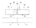
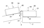
まず図1および図2を参照して、この扉の施錠装置10は、食器棚などの収納家具1に設けられている扉体2,3の各々にその戸当たり4を挟んで左右対称的に取り付けられる2つの固定ユニット20,30を備えている。なお、適用される扉は回転式であれば片開き式であってもよい。そもそも、スライド式扉は地震によっては開き難いため本発明の対象外である。
First, referring to FIG. 1 and FIG. 2, the
図2に示すように、固定ユニット20,30のうち一方の固定ユニット20は出没可能なロックレバー40を備え、他方の固定ユニット30はロックレバー40の受け具として用いられることからして、一方の固定ユニット20が能動側で他方の固定ユニット30が受動側である。一方の固定ユニット20を能動側の第1固定ユニット,他方の固定ユニットを受動側の第2固定ユニットとして、以下にその各構成を説明する。
As shown in FIG. 2, one of the
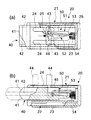
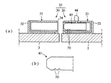
図3(a)および(b)を参照して、第1固定ユニット20は角筒状に形成された第1ユニットハウジング21を備えている。第1ユニットハウジング21は扉体2に対して両面粘着テープもしくはネジなどにより直接的に固定されてもよいが、この例において、第1ユニットハウジング21は第1ベース板22を介して扉体2に取り付けられる。
Referring to FIGS. 3A and 3B, the first fixed
すなわち、第1ユニットハウジング21と第1ベース板22は相対的にスライド可能であって、第1ベース板22を例えば両面粘着テープ23により扉体2に固定したのち、第1ベース板22に第1ユニットハウジング21をスライドさせて係合することにより第1ユニットハウジング21が第1ベース板22を介して扉体2に固定される。
That is, the
これによれば、図11に示すように、扉体2,3に対して強制的に開方向に力が加わった場合に、扉2,3の開き量に応じて、第1ベース板21に対して第1ユニットハウジング21がスライドして、ズレを吸収することにより、扉体2,3が開くのを防止することができる。
According to this, as shown in FIG. 11, when a force is forcibly applied to the
図3(b)において、第1ユニットハウジング21は左端側が開放され、右端側が閉塞されている。第1ユニットハウジング21の内部には、第2固定ユニット30に向けて出没(進入・後退)するロックレバー40と、ロックレバー40を所定位置に保持するロック制御手段50とが設けられている。
In FIG. 3B, the
第1ユニットハウジング21の上面には、内部のロックレバー40を操作するためのスライド可能な操作ノブ44が設けられている。この例において、操作ノブ44はその両端に2本の固定ピン45を備え、固定ピン45をロックレバー40に穿設されている差込孔43(図4(a)参照)に差し込むことによりロックレバー40と連結される。なお、図3(a)に示すように、第1ユニットハウジング21の上面には固定ピン45を移動可能とするためのスライド孔24が平行に2箇所設けられている。
On the upper surface of the
ロックレバー40は合成樹脂の成型品からなり、第1ユニットハウジング21内に沿ってスライド可能な角柱体状に形成されている。図4(a)にも示すように、ロックレバー40はその先端に山切り状(矢尻状)にカットされたテーパー面41、41を有し、また、ロックレバー40の両側面には進退方向に沿ってガイド溝42が形成されている。
The
テーパー面41,41は、扉体2,3にかかる回転方向の力をロックレバー40に対して直線方向の力として与えるために必要とされる傾斜面で、この例ではロックレバー40の進退方向に対して約45°の角度になるように設けられている。
The taper surfaces 41 and 41 are inclined surfaces that are required to apply a rotational force applied to the
また、両側面にガイド溝42を形成し第2固定ユニット30側のガイドレール33(図2参照)と噛み合せるようにしたことにより、ロック状態において過大な負荷が掛けられた場合であっても簡単にはロックが解除されないようにしている。
Further, by forming
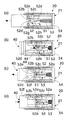
次に、図4(a)〜図4(c)を参照して、ロックレバー40の動きを制御するロック制御手段50について説明する。ロック制御手段50はプッシュラッチ式で、ロック制御手段50にはロックレバー40の後端側に一体的に取り付けられるラッチピンガイド部51と、ラッチピン53と、ロックレバー40を常時第2固定ユニット30側に向けて付勢するコイルバネ54とが含まれている。
Next, the lock control means 50 that controls the movement of the
ラッチピン53は金属棒の両端をほぼ90°に折り曲げてコ字状に形成されており、先端の鉤部がラッチピンガイド部51に形成されているラッチガイド溝52内に落とし込まれ、後端の鉤部が第1ユニットハウジング21の内壁に垂直軸線を中心として回転可能に軸支されている。
The
この例において、コイルバネ54は第1ユニットハウジング21の内壁とラッチピンガイド部51との間に配置された圧縮バネからなり、ラッチピンガイド部51を介してロックレバー40を常に押し出す方向にバネ付勢している。
In this example, the
ラッチピンガイド部51はロックレバー40と一体になって進退するのに対して、ラッチピン53は進退しないが、ラッチピン53の先端部はラッチピンガイド部51の動きにしたがってラッチガイド溝52内を相対的に移動する。
The latch
図4(b),(c)を参照して、ラッチガイド溝52には、ラッチピン53を施錠位置52aから第1解錠位置52bに向けて案内する往路側の第1ラッチガイド溝Aと、ラッチピン53を第1解錠位置52bから待機位置52cに向けて案内する中間の第2ラッチガイド溝Bと、ラッチピン53を待機位置52cから一旦第2解錠位置52dに導いてから施錠位置52aに戻す復路側の第3ラッチガイド溝Cとが含まれている。
4B and 4C, the
施錠位置52aは、ロックレバー40をコイルバネ54の付勢力にて図8(a)に示すように第2固定ユニット30内に向けて完全に押し出した位置(ロック位置)である。第1解錠位置52bは、ユーザーが操作ノブ44に指をかけて図8(b)に示すようにロックレバー40を第1固定ユニット20内に引き戻した位置(アンロック位置)で、この位置で扉を開くことができる。
The
待機位置52cは、上記第1解錠位置52bで操作ノブ44から指を離した際にコイルバネ54の付勢力にて第1解錠位置52bよりも突出し図8(c)に示すようにロックレバー40の先端にあるテーパー面41が第2固定ユニット30の端縁に当接し得るように保持される位置(セミロック位置)である。第2解錠位置52cは、待機位置52cを中心として上記第1解錠位置52bと対称的な位置に存在し、待機位置52cにあるロックレバー40が閉じられてくる扉によって第1固定ユニット20内に押し戻される位置である。
When the finger is released from the
ラッチガイド溝52のうち、往路側の第1ラッチガイド溝Aはその溝底が施錠位置52aから第1解錠位置52bに向かうにしたがって上り勾配となる傾斜面で第1解錠位置52bに至る直前にピン戻り防止用の段差面52eが形成されている。
Of the
中間の第2ラッチガイド溝Bには、第1解錠位置52bから待機位置52cを経て第2解錠位置52dに至るまでの経路が含まれ、第1解錠位置52bと待機位置52cとの間にはピン戻り防止用の段差面52fが形成されており、また、待機位置52cと第2解錠位置52dとの間にもピン戻り防止用の段差面52gが形成されている。
The intermediate second latch guide groove B includes a path from the first unlocking
復路側の第3ラッチガイド溝Cは、その溝底が第2解錠位置52dから施錠位置52aに向かうにしたがって上り勾配となる傾斜面で施錠位置52aに至る直前にピン戻り防止用の段差面52hが形成されている。これによれば、各段差面52e〜52hによってラッチピン53の先端部が各ラッチガイド溝A〜Cを逆戻りすることなく確実に一方通行させることができる。
The third latch guide groove C on the return path side is a step surface for preventing pin return immediately before reaching the
再び図3(a)を参照して、第1ユニットハウジング21の上面にはラッチピン53の先端部と後端の軸支部とを目視可能な確認窓25,26が設けられている。確認窓25,26は第1ユニットハウジング21の上部から内部の一部が見える透孔からなり、そこからプッシュピン53の端部が見え動作を確認できる。また、例えばプッシュピン53がラッチガイド溝52から外れた場合には、そこから工具などを差し込んで正常な位置に直すこともできる。
Referring to FIG. 3A again,
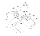
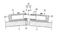
次に、受動側の第2固定ユニット30について再び図2を参照しながら説明する。第2固定ユニット30は上記第1固定ユニット20と同様に角筒状に形成された第2ユニットハウジング31を備え、第2ベース板32を介して扉体3側に取り付けられてよい。第2ベース板32は上記第1固定ユニット20側の第1ベース板22と同じ構成であってよいため、その説明は省略する。
Next, the second fixed
第2ユニットハウジング31は、第1ユニットハウジング21と対向する一端側が開放され他端側が閉塞されている。第2ユニットハウジング31の対向する内側面にはロックレバー40のガイド溝42と摺動可能に係合するガイドレール33が設けられている。
The
また、第2ユニットハウジング31は、第1固定ユニット20と対向する側の端縁が丸く削られたテーパー面34であることが好ましい。これによれば、扉体2,3の閉扉時に待機位置52cに保持されているロックレバー40の先端(テーパー面41)を容易に乗り越えることができる。
In addition, the
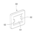
上記した第1および第2の固定ユニット20,30を扉体2,3にそれぞれ取り付ける際、第1固定ユニット20側のロックレバー40が第2固定ユニット30側の第2ユニットハウジング31内に的確に嵌合するように、その相対的な位置および距離(間隔)を位置決めする必要がある。そこで、本発明による扉の施錠装置10は、各固定ユニット20,30同士の相対的な取付位置を位置決めする図6に示すスペーサ60を備えている。
When the first and second
スペーサ60は、固定ユニット20,30の間の間隔を適正に保つ厚さ(この例では3mm)を有する好ましくは合成樹脂製の板体からなり、中央にはロックレバー40が差し込まれるガイド孔61が設けられている。
The
これによれば、図7に示すようにあらかじめスペーサ60を挟んで各固定ユニット20,30同士をつないだ状態として扉体2,3に取り付けることにより最適な位置で設置することができる。なお、ガイド孔61の両側面にはガイド溝42に合致する凸部62が設けられていることが好ましい。
According to this, as shown in FIG. 7, it can install in the optimal position by attaching each fixing
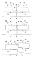
次に、図5(a)〜(d)および図8(a)〜(c)を参照して、本発明による扉の施錠装置10の一連のプッシュラッチ動作について説明する。ここで、図5(a)および図8(a)に示すように、ロックレバー40がコイルバネ54により付勢されて第2固定ユニット30内に深く進入しているロック状態、すなわちロックレバー40がラッチピン53により施錠位置52aに保持されているときを初期位置とする。
Next, a series of push latch operations of the
この初期位置のロック状態から扉を開けるには、まず、操作ノブ44に指をかけてロックレバー40をコイルバネ54の付勢力に抗して右側にスライドさせ、図5(b)に示すようにラッチピン53の先端部が第1解錠位置52bに突き当るまで移動させる。これにより、図8(b)に示すようにロックレバー40が第2固定ユニット30から外されるため、ユーザーは扉を開けることができる。
In order to open the door from the locked state at the initial position, first, a finger is put on the
扉を開けたのち操作ノブ44から指を離すと、コイルバネ54によりロックレバー40が押し出されるが、このときラッチピン53の先端部が待機位置52cの溝に引っかかるため、ロックレバー40は図5(c)に示すように図5(b)の解錠位置より若干飛び出した位置に保持される。すなわち、この待機位置52cにおいてロックレバー40は図8(c)に示すようにその先端のテーパー面41が第2固定ユニット30の端縁と当接するように保持される。
When the finger is released from the
次に、扉が閉められる方向に動かされると、図8(c)に示すようにロックレバー40のテーパー面41が第2固定ユニット30の端縁に当接し、これによりロックレバー40が図5(d)に示すようにコイルバネ54の付勢力に抗して押し戻される。このとき、ラッチピン53の先端部は待機位置52cから第2解錠位置52dに移動する。
Next, when the door is moved in the closing direction, the tapered
そして、扉が完全に閉じられ第2固定ユニット30がロックレバー40のテーパー面41を乗り越えると、ラッチピン53の先端部が第2解錠位置52dから復路側の第3ラッチガイド溝Cに入るため、ロックレバー40がコイルバネ54により押し出され図5(a)および図8(a)に示す初期位置に戻される。
When the door is completely closed and the
すなわち、ロックレバー40はラッチピン53の先端部が復路側の第3ラッチガイド溝Cを通って施錠位置52aに至ることにより第2固定ユニット30の第2ユニットハウジング31内に深く進入する。このようにして、本発明によれば扉を閉めることに伴って自動的にロックがかかる。
That is, the
図8(a)〜(c)は第1固定ユニット20側の扉体2を開閉した場合の動作を示しているが、第2固定ユニット30側の扉体3を開閉する場合にも、図9に示すように第2ユニットハウジング31の端縁がロックレバー40の先端のテーパー面41に当接してロックレバー40を一旦押し戻すため上記と同様に自動的にロックがかかる。
FIGS. 8A to 8C show the operation when the
すなわち、扉体2,3をともに開け離した状態で扉を閉める場合、いずれか一方の扉体を先に閉めてから、他方の扉体を閉めるようにすれば自動的にロックをかけることができる。
That is, when the door is closed with both the
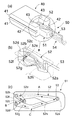
上記実施形態において、第1固定ユニット20と第2固定ユニット30は、第1固定ユニット20側に設けられたロックレバー40を第2固定ユニット30内に向けて差し込むことにより、扉体2,3の開閉を規制しているが、より強固に固定する方法の一例を図10(a),(b)に示す。なお、上記実施形態と同一もしくは同一を見なされる箇所には同じ参照符号を付し、説明は省略する。
In the above embodiment, the first fixed
この施錠装置10は、その特徴としてロックレバー40の一部に脱落防止手段としての係止溝70が設けられている。係止溝70は、ロックレバー40の上記扉体2,3に対向する側の底面に幅方向に沿って逆V字状に刻まれた切欠溝からなり、この例では、2コの係止溝70,70が第1ベース板22のスライド方向に沿って隣接して設けられている。
As a feature of the
これによれば、図11に示すように、扉体2,3に対して開方向に強制的に力が加わった場合、係止溝70が相手方の第2固定ユニット30の開口縁に引っ掛かることにより、ロックレバー40が第2固定ユニット30から抜け出て、扉体2,3が開いてしまうことを防止することができる。このような態様も本発明に含まれる。
According to this, as shown in FIG. 11, when a force is forcibly applied in the opening direction to the
なお、この例において脱落防止手段は切欠溝70からなるが、切欠溝70以外にエンボス加工などによる高摩擦化処理を施してもよい。
In this example, the drop-off prevention means includes the
また、片開き扉の場合には第1固定ユニット20と第2固定ユニット30のうち、その一方を開き戸側に設置し、他方をその戸当たり側の壁に設置すればよい。本発明の扉施錠装置は食器棚のみならず、例えば部屋の扉などにも適用できることはもちろんである。
In the case of a single door, one of the first fixed
1 収納家具
2,3 扉体
4 戸当たり
10 扉の施錠装置
20 第1固定ユニット
30 第2固定ユニット
40 ロックレバー
41 テーパー面
42 ガイド溝
44 操作ノブ
50 ロック制御手段
51 ラッチピンガイド部
52 ラッチガイド溝
53 ラッチピン
54 コイルバネ
60 スペーサ
70 切欠溝
DESCRIPTION OF
Claims (9)
上記扉体の戸当たりを挟んで左右一対として対向的に配置される第1および第2の固定ユニットを含み、上記第1固定ユニットには、上記第2固定ユニットに対して進入・後退可能なロックレバーと、上記ロックレバーを上記第2固定ユニットに向かう進入方向に常時付勢するバネ手段と、上記ロックレバーを上記第2固定ユニット内に深く進入している施錠位置から上記バネ手段の付勢力に抗して解錠位置に後退させる操作ノブと、上記ロックレバーの動きを制御するロック制御手段とが設けられ、
上記ロック制御手段は、上記ロックレバーを上記解錠位置から上記扉体が閉扉可能な状態で上記ロックレバーの先端側の一部分が上記第2固定ユニットの端縁に当接し得る待機位置に案内するとともに、上記待機位置で上記ロックレバーが上記第2固定ユニットと当接して後退させられると上記ロックレバーの上記待機位置から上記施錠位置への移動を可能とすることを特徴とする扉の施錠装置。 In a door locking device that automatically locks when a rotary door provided in a cupboard is closed,
It includes first and second fixed units that are opposed to each other as a pair of left and right across the door contact of the door body, and the first fixed unit can enter and retract with respect to the second fixed unit. A lock lever, spring means for constantly urging the lock lever in an approaching direction toward the second fixed unit, and attachment of the spring means from a locked position where the lock lever has entered deeply into the second fixed unit. An operation knob that moves back to the unlocked position against the force and a lock control means that controls the movement of the lock lever are provided,
The lock control means guides the lock lever from the unlocked position to a standby position where a part of the front end side of the lock lever can come into contact with the edge of the second fixed unit in a state where the door can be closed. In addition, when the lock lever is brought into contact with the second fixed unit and retracted at the standby position, the lock lever can be moved from the standby position to the lock position. .
Each of the fixing units has a base plate attached to a mounting surface via a predetermined fixing means, and the base plate is slidably attached to each of the fixing units. The door locking device according to any one of 1 to 8.
Priority Applications (1)
| Application Number | Priority Date | Filing Date | Title |
|---|---|---|---|
| JP2005175216A JP4603939B2 (en) | 2004-06-15 | 2005-06-15 | Door locking device |
Applications Claiming Priority (2)
| Application Number | Priority Date | Filing Date | Title |
|---|---|---|---|
| JP2004176374 | 2004-06-15 | ||
| JP2005175216A JP4603939B2 (en) | 2004-06-15 | 2005-06-15 | Door locking device |
Publications (2)
| Publication Number | Publication Date |
|---|---|
| JP2006029068A true JP2006029068A (en) | 2006-02-02 |
| JP4603939B2 JP4603939B2 (en) | 2010-12-22 |
Family
ID=35895755
Family Applications (1)
| Application Number | Title | Priority Date | Filing Date |
|---|---|---|---|
| JP2005175216A Expired - Fee Related JP4603939B2 (en) | 2004-06-15 | 2005-06-15 | Door locking device |
Country Status (1)
| Country | Link |
|---|---|
| JP (1) | JP4603939B2 (en) |
Cited By (5)
| Publication number | Priority date | Publication date | Assignee | Title |
|---|---|---|---|---|
| JP2007224544A (en) * | 2006-02-22 | 2007-09-06 | Murakoshi Mfg Corp | Installation tool of lock device and lock device unit |
| KR101179574B1 (en) | 2010-11-24 | 2012-09-07 | 김완호 | Automatic locking device for side-by-side door |
| JP2013001403A (en) * | 2011-06-13 | 2013-01-07 | Sanko Co Ltd | Folding container |
| JP2013160022A (en) * | 2012-02-08 | 2013-08-19 | Panasonic Corp | Latch lock device and door provided with the same |
| DE202009019038U1 (en) | 2008-08-13 | 2015-09-16 | Ormco Corp. | Aesthetic orthodontic bracket |
Citations (3)
| Publication number | Priority date | Publication date | Assignee | Title |
|---|---|---|---|---|
| JPH0348075U (en) * | 1989-09-14 | 1991-05-08 | ||
| JPH11166344A (en) * | 1997-12-05 | 1999-06-22 | Nifco Inc | Latch |
| JP2002317581A (en) * | 2001-04-20 | 2002-10-31 | Daiken Trade & Ind Co Ltd | Latch device and inward and outward double swing door |
-
2005
- 2005-06-15 JP JP2005175216A patent/JP4603939B2/en not_active Expired - Fee Related
Patent Citations (3)
| Publication number | Priority date | Publication date | Assignee | Title |
|---|---|---|---|---|
| JPH0348075U (en) * | 1989-09-14 | 1991-05-08 | ||
| JPH11166344A (en) * | 1997-12-05 | 1999-06-22 | Nifco Inc | Latch |
| JP2002317581A (en) * | 2001-04-20 | 2002-10-31 | Daiken Trade & Ind Co Ltd | Latch device and inward and outward double swing door |
Cited By (5)
| Publication number | Priority date | Publication date | Assignee | Title |
|---|---|---|---|---|
| JP2007224544A (en) * | 2006-02-22 | 2007-09-06 | Murakoshi Mfg Corp | Installation tool of lock device and lock device unit |
| DE202009019038U1 (en) | 2008-08-13 | 2015-09-16 | Ormco Corp. | Aesthetic orthodontic bracket |
| KR101179574B1 (en) | 2010-11-24 | 2012-09-07 | 김완호 | Automatic locking device for side-by-side door |
| JP2013001403A (en) * | 2011-06-13 | 2013-01-07 | Sanko Co Ltd | Folding container |
| JP2013160022A (en) * | 2012-02-08 | 2013-08-19 | Panasonic Corp | Latch lock device and door provided with the same |
Also Published As
| Publication number | Publication date |
|---|---|
| JP4603939B2 (en) | 2010-12-22 |
Similar Documents
| Publication | Publication Date | Title |
|---|---|---|
| JP4603939B2 (en) | Door locking device | |
| US7967402B2 (en) | Slide rail unit with retaining function | |
| KR20160105864A (en) | Sliding-door closer set | |
| US20050194797A1 (en) | Closure Latch Assembly | |
| US20130056995A1 (en) | Sliding Pin Lock Mechanism for Overhead Door | |
| JP6761018B2 (en) | Locking mechanism for objects that can move relative to each other | |
| JP5258778B2 (en) | Seismic latch structure | |
| US6634726B1 (en) | Multiple drawer cabinet allowing one drawer opened at a time | |
| JP3750937B2 (en) | Lock handle device for drawer rotation operation type door | |
| JP6527461B2 (en) | Movable trigger device and sliding door including the same | |
| CA2708700A1 (en) | Releasable tenon for locking system | |
| JP2012519243A (en) | Locking mechanism for padlocks, for example, can be latched and re-locked after baggage inspection | |
| JP2006307512A (en) | Lid opening/closing device | |
| JP2006192041A (en) | Slide rail | |
| WO2011162424A1 (en) | Device for unlocking lock recognizing punched card | |
| JP2009074319A (en) | Opening section equipment | |
| JP3181194U (en) | Fixing tool for door opening prevention tool | |
| JPWO2018155335A1 (en) | Safety switch | |
| JPS6017485Y2 (en) | Interlock device | |
| JP3699857B2 (en) | latch | |
| JP4932540B2 (en) | Button lock device | |
| JP2012052377A (en) | Locking device of drawer storage | |
| AU2017268520B2 (en) | A lock assembly | |
| JP3041307B2 (en) | Storage box with wing, auto lock device and dead bolt used for the storage box | |
| JP2024041045A (en) | security lock |
Legal Events
| Date | Code | Title | Description |
|---|---|---|---|
| A621 | Written request for application examination |
Free format text: JAPANESE INTERMEDIATE CODE: A621 Effective date: 20080521 |
|
| A977 | Report on retrieval |
Free format text: JAPANESE INTERMEDIATE CODE: A971007 Effective date: 20100621 |
|
| TRDD | Decision of grant or rejection written | ||
| A01 | Written decision to grant a patent or to grant a registration (utility model) |
Free format text: JAPANESE INTERMEDIATE CODE: A01 Effective date: 20100908 |
|
| A01 | Written decision to grant a patent or to grant a registration (utility model) |
Free format text: JAPANESE INTERMEDIATE CODE: A01 |
|
| A61 | First payment of annual fees (during grant procedure) |
Free format text: JAPANESE INTERMEDIATE CODE: A61 Effective date: 20101004 |
|
| FPAY | Renewal fee payment (event date is renewal date of database) |
Free format text: PAYMENT UNTIL: 20131008 Year of fee payment: 3 |
|
| R150 | Certificate of patent or registration of utility model |
Ref document number: 4603939 Country of ref document: JP Free format text: JAPANESE INTERMEDIATE CODE: R150 Free format text: JAPANESE INTERMEDIATE CODE: R150 |
|
| R250 | Receipt of annual fees |
Free format text: JAPANESE INTERMEDIATE CODE: R250 |
|
| R250 | Receipt of annual fees |
Free format text: JAPANESE INTERMEDIATE CODE: R250 |
|
| R250 | Receipt of annual fees |
Free format text: JAPANESE INTERMEDIATE CODE: R250 |
|
| R250 | Receipt of annual fees |
Free format text: JAPANESE INTERMEDIATE CODE: R250 |
|
| R250 | Receipt of annual fees |
Free format text: JAPANESE INTERMEDIATE CODE: R250 |
|
| S111 | Request for change of ownership or part of ownership |
Free format text: JAPANESE INTERMEDIATE CODE: R313117 |
|
| R350 | Written notification of registration of transfer |
Free format text: JAPANESE INTERMEDIATE CODE: R350 |
|
| R250 | Receipt of annual fees |
Free format text: JAPANESE INTERMEDIATE CODE: R250 |
|
| R250 | Receipt of annual fees |
Free format text: JAPANESE INTERMEDIATE CODE: R250 |
|
| R250 | Receipt of annual fees |
Free format text: JAPANESE INTERMEDIATE CODE: R250 |
|
| R250 | Receipt of annual fees |
Free format text: JAPANESE INTERMEDIATE CODE: R250 |
|
| LAPS | Cancellation because of no payment of annual fees |