JP2006026155A - Tubular prosthesis - Google Patents
Tubular prosthesis Download PDFInfo
- Publication number
- JP2006026155A JP2006026155A JP2004210322A JP2004210322A JP2006026155A JP 2006026155 A JP2006026155 A JP 2006026155A JP 2004210322 A JP2004210322 A JP 2004210322A JP 2004210322 A JP2004210322 A JP 2004210322A JP 2006026155 A JP2006026155 A JP 2006026155A
- Authority
- JP
- Japan
- Prior art keywords
- warp
- formula
- adjacent
- prosthesis
- warps
- Prior art date
- Legal status (The legal status is an assumption and is not a legal conclusion. Google has not performed a legal analysis and makes no representation as to the accuracy of the status listed.)
- Pending
Links
Images


Abstract
Description
本発明は、人工血管などの管状の人工器官に関し、取扱性及び目止め性に優れる人工器官に関するものである。 The present invention relates to a tubular prosthesis such as an artificial blood vessel, and relates to a prosthesis excellent in handleability and sealability.
ポリエステルなどを用いて平織りなど種々の織物などの管状の人工器官が、移植用の人工血管として利用されている。 Tubular prostheses such as various fabrics such as plain weave using polyester or the like are used as artificial blood vessels for transplantation.
特許文献1には、実質的にポリエステル樹脂のみから構成され、かつ37℃の水で測定した有孔度が15ml/cm2・min・120mmHg以下の人工血管が開示されている。
特許文献2には、繊維を織、編、組、絡処理のうちいずれかまたは2つ以上を用いて管状に構成してなる人工血管において、前記繊維が、部分的に融着用繊維を含むものであることを特徴とする人工血管が開示されている。
Patent Document 1 discloses an artificial blood vessel that is substantially composed only of a polyester resin and has a porosity of 15 ml / cm 2 · min · 120 mmHg or less measured with water at 37 ° C.
In Patent Document 2, in an artificial blood vessel in which a fiber is formed into a tubular shape by using any one or two of woven, knitted, braided, and entangled treatments, the fiber partially includes a fusion fiber. An artificial blood vessel characterized by this is disclosed.
編みや織りにより製造される人工血管は、柔軟性や器質化を向上させるために、編目や織り目を大きくする必要がある。しかし、編目や織り目を大きくすると、得られる人工血管は強度が低下したり、目止め性が低下したり、鉗子操作が困難になることが考えられる。 Artificial blood vessels manufactured by knitting or weaving need to have large stitches and weaves in order to improve flexibility and organization. However, if the stitches or weaves are enlarged, the strength of the resulting artificial blood vessel may be reduced, the sealing performance may be reduced, or forceps operation may be difficult.
本発明は、ポリエステルなどの合成樹脂の平織りの人工血管で、目止め性が向上し、鉗子操作性が向上し、強度低下のない人工器官の提供を目的とした。 An object of the present invention is to provide a prosthetic device which is a plain-woven artificial blood vessel made of a synthetic resin such as polyester and has improved sealing properties, improved forceps operability, and no reduction in strength.
本発明は、周方向に径の異なる経糸を、特定の条件を満たすように用いて、平織りなどの織り構造の管状の人工血管を作成することにより、織り目を大きくすることなしに、目止め性に優れ、鉗子操作性に優れている人工血管が得られることを見出した。 The present invention uses warp yarns having different diameters in the circumferential direction so as to satisfy a specific condition, and creates a tubular artificial blood vessel having a woven structure such as a plain weave without increasing the weave. And found that an artificial blood vessel excellent in forceps operability can be obtained.
本発明は、
緯糸及び経糸からなる織り構造の管状の人工器官であり、
この管状の人工器官の経糸が、
1)周方向に隣接する2本の経糸(経糸A及び経糸B)が式(1)の関係を満たす部分が少なくとも1カ所あり、
2)経糸Bから、周方向に隣接する2本の経糸が式(1)の関係を満たす部分の経糸までの周方向に配列されている経糸において、経糸とそれに隣接する経糸とが、式(2)又は式(3)の関係を満たすように配置されていることを特徴とする人工器官を提供することである。
The present invention
It is a tubular prosthesis with a woven structure consisting of wefts and warps,
The warp of this tubular prosthesis
1) There are at least one portion where two warps adjacent to the circumferential direction (warp A and warp B) satisfy the relationship of formula (1),
2) In a warp in which two warps adjacent in the circumferential direction from warp B are arranged in the circumferential direction from the portion satisfying the relationship of formula (1), the warp and the adjacent warp are expressed by the formula ( It is to provide a prosthesis characterized by being arranged so as to satisfy the relationship of 2) or formula (3).
さらに本発明は、
緯糸及び経糸からなる織り構造の管状の人工器官であり、
この管状の人工器官の経糸が、
1)周方向に隣接する2本の経糸(経糸A及び経糸B)が式(1)の関係を満たす部分が少なくとも1カ所あり、
2)経糸Bから、周方向に隣接する2本の経糸が式(1)の関係を満たす部分の経糸までの周方向に配列されている経糸において、経糸とそれに隣接する経糸とが、式(2)と式(3)の順序、又は式(3)と式(2)の順序で交互に関係を満たすように配置されていることを特徴とする人工器官を提供することである。
Furthermore, the present invention provides
It is a tubular prosthesis with a woven structure consisting of wefts and warps,
The warp of this tubular prosthesis
1) There are at least one portion where two warps adjacent to the circumferential direction (warp A and warp B) satisfy the relationship of formula (1),
2) In a warp in which two warps adjacent in the circumferential direction from warp B are arranged in the circumferential direction from the portion satisfying the relationship of formula (1), the warp and the adjacent warp are expressed by the formula ( It is to provide a prosthesis characterized by being arranged so as to satisfy the relationship alternately in the order of 2) and formula (3) or in the order of formula (3) and formula (2).
本発明の人工器官の好ましい態様をしめす。
経糸は、奇数であることが好ましい。
周方向に隣接する2本の経糸(経糸A及び経糸B)が式(1)の関係を満たす部分は、1以上の奇数カ所有することが好ましい。
織り構造は、平織りであることが好ましい。
A preferred embodiment of the prosthesis of the present invention is shown.
The warp is preferably an odd number.
It is preferable that two or more warp yarns (warp yarn A and warp yarn B) adjacent to each other in the circumferential direction have an odd number of one or more odd numbers.
The woven structure is preferably a plain weave.
本発明の人工器官は、柔軟性に優れ、取り扱い性、器質化が良好で、治癒性に優れ、コーティング剤又はプロクロッティング処理による目止め性能に優れ、鉗子による遮断が容易になる。 The prosthesis of the present invention is excellent in flexibility, easy to handle and organize, excellent in curability, excellent in sealing performance by a coating agent or pro-clotting treatment, and easily blocked by forceps.
以下に、本発明の実施の形態を図面により詳細に説明する。ただし、本発明は、これらの実施の形態に限定されるものではない。 Embodiments of the present invention will be described below in detail with reference to the drawings. However, the present invention is not limited to these embodiments.
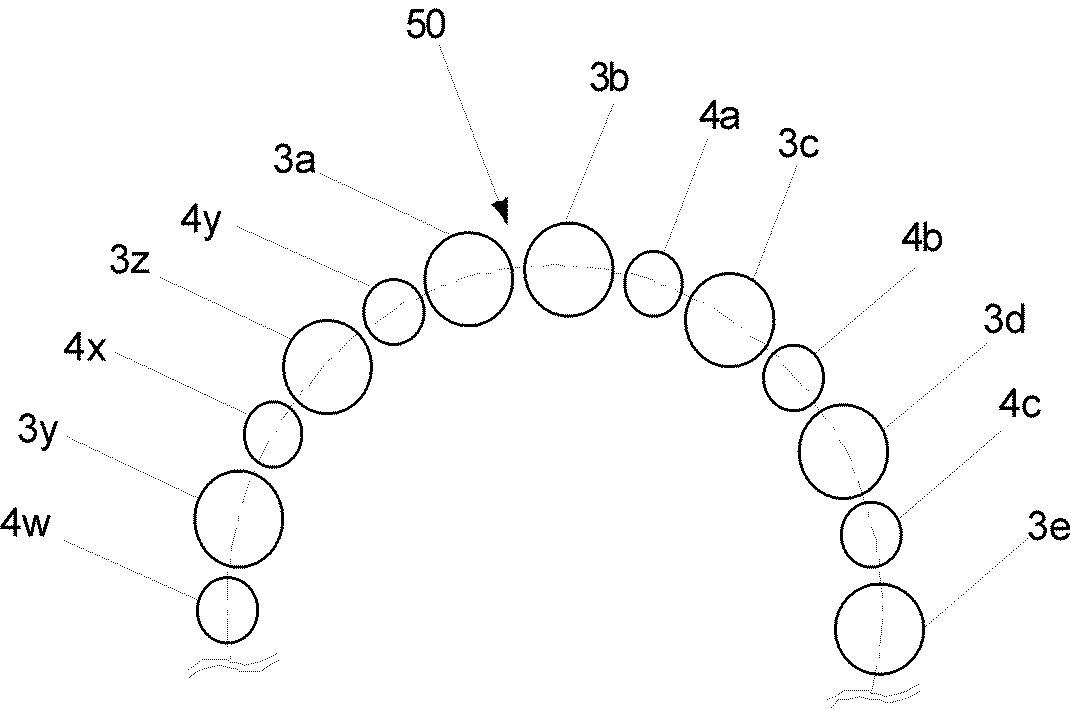
図1には、本発明の一例である平織りの管状の人工血管10の軸方向の縦断面の一部切り欠き部分における、経糸の周方向の配列を示す模式図であり、緯糸は省略されている。人工血管10の経糸の数は、奇数である。
人工血管10の経糸の周方向の配列は、経糸1aから時計回りの周方向に経糸が、経糸(1b,2a、1c、2b、1d、・・・・、1y,2x,1z,2y)の順に配置されている。
周方向に並ぶ2本の経糸(1a、1b)は、経糸1aを経糸Aとし、経糸1bを経糸Bとし、下記式(1)の条件を満たしている。経糸1bと時計回りに隣接する経糸2aとは、式(3)の関係を満たし、経糸2aと時計回りに隣接する経糸1cとは、式(2)の関係を満たしている。さらに経糸1cと経糸2bは式(3)の関係を満たし、経糸2bと時計回りに隣接する経糸1dとは、式(2)の関係を満たしている。このように式(1)の条件を満たしている経糸1bより周方向に時計回りに配置されている経糸は、それと時計方向に隣接する経糸とが、式(3)と式(2)の順序で交互に関係を満たすように配置されている。また、経糸1aとそれより半時計回りに配置されている経糸2yとの関係は、経糸2yと時計回りに隣接する経糸1aとは、式(2)の関係を満たしている。
人工血管10で使用されている経糸は、同程度の太さの経糸(1a,1b,1c,1d,・・・,1y,1z)(例えば、第一群とする)と、それらより太く同程度の太さの経糸(2a,2b,2c,・・・,2x,2y,2z)(例えば、第二群とする)との2種類である。
人口血管10では、周方向に並ぶ2本の経糸が、下記式(1)の条件を満たしている部分を複数有することができ、例えば1以上の奇数カ所有することが出来る。
FIG. 1 is a schematic diagram showing a circumferential arrangement of warp yarns in a partially cut-away portion of an axial longitudinal section of a plain weave tubular
In the circumferential arrangement of the warp of the
The two warp yarns (1a, 1b) arranged in the circumferential direction satisfy warp A as warp A and warp B as warp B, and satisfy the condition of the following formula (1). The
The warps used in the
In the
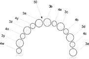
図2には、本発明の別の一例である平織りの管状の人工血管50の軸方向の縦断面の一部切り欠き部分における、経糸の周方向の配列を示す模式図であり、緯糸は省略されている。人工血管50の経糸の数は、奇数である。
人工血管50の経糸の周方向の配列は、経糸3aから時計回りの周方向に経糸が、経糸(3b,4a、3c、4b、3d、・・・・、3y,4x,3z,4y)の順に配置されている。
周方向に並ぶ2本の経糸(3a、3b)は、経糸3aを経糸Aとし、経糸3bを経糸Bとすると下記式(1)の条件を満たしている。
経糸3bと時計回りに隣接する経糸4aとは、式(2)の関係を満たし、経糸4aと時計回りに隣接する経糸3cとは、式(3)の関係を満たしている。さらに経糸3cと経糸4bは式(2)の関係を満たし、経糸4bと時計回りに隣接する経糸3dとは、式(3)の関係を満たしている。このように下記式(1)の条件を満たしている経糸3bより周方向に時計回りに配置されている経糸は、それと時計方向に隣接する経糸とが、式(2)と式(3)の順序で交互に関係を満たすように配置されている。また、経糸3aとそれより半時計回りに配置されている経糸4yとの関係は、経糸4yと時計回りに隣接する経糸3aとは、式(3)の関係を満たしている。
人工血管50で使用されている経糸は、同程度の太さの経糸(3a,3b,3c,3d,・・・,3y,3z)(例えば、第二群とする)と、それらより細く同程度の太さの経糸(4a,4b,4c,・・・,4x,4y,4z)(例えば、第一群とする)との2種類である。人口血管50では、周方向に並ぶ2本の経糸が、下記式(1)の条件を満たしている部分を複数有することができ、例えば1以上の奇数カ所有することが出来る。
FIG. 2 is a schematic view showing a circumferential arrangement of warp yarns in a partially cut-out portion of an axial longitudinal section of a plain weave tubular
The circumferential arrangement of the warps of the
The two warps (3a, 3b) arranged in the circumferential direction satisfy the condition of the following formula (1) when the warp 3a is a warp A and the
The
The warp used in the
上記式(1)、式(2)及び式(3)において、
R1は、0.9であり、好ましくは0.92であり、さらに好ましくは0.95であり、特に好ましくは0.98であり、
R2は、1.1であり、好ましくは1.2であり、さらに好ましくは1.3であり、特に好ましくは1.4であり、
R3は、0.9であり、好ましくは0.8であり、特に好ましくは0.7であり、
R4は、1.1であり、好ましくは1.2であり、さらに好ましくは1.3であり、特に好ましくは1.4である。
In the above formula (1), formula (2) and formula (3),
R 1 is 0.9, preferably 0.92, more preferably 0.95, particularly preferably 0.98,
R 2 is 1.1, preferably 1.2, more preferably 1.3, particularly preferably 1.4,
R 3 is 0.9, preferably 0.8, particularly preferably 0.7,
R 4 is 1.1, preferably 1.2, more preferably 1.3, and particularly preferably 1.4.
人工器官において、使用する経糸は、同程度の太さの経糸(第一群)と、これより太く同程度の太さの経糸(第二群)の少なくとも2種類の太さの経糸を用いることが好ましい。
人工器官に使用する経糸は、一例として、
(i)式(1)を満たす経糸が第一群の経糸であり、式(2)の経糸が第二群の経糸であり、これに隣接する経糸が第一群である組み合わせ、
(ii)式(1)を満たす経糸が第二群の経糸であり、式(2)の経糸が第一群の経糸であり、これに隣接する経糸が第二群である組み合わせ、
(iii)式(1)を満たす経糸が第一群の経糸であり、式(2)の経糸が第一群の経糸であり、これに隣接する経糸が第二群である組み合わせ、
(iv)式(1)を満たす経糸が第二群の経糸であり、式(2)の経糸が第二群の経糸であり、これに隣接する経糸が第一群である組み合わせ、などを挙げることが出来る。
In the prosthesis, the warp to be used should be at least two types of warp (first group) and thicker warp (second group). Is preferred.
As an example, the warp used in the prosthesis
(I) A combination in which the warp satisfying formula (1) is the first group of warps, the warp of formula (2) is the second group of warps, and the warp adjacent to this is the first group,
(Ii) A combination in which the warp satisfying formula (1) is the second group of warps, the warp of formula (2) is the first group of warps, and the warp adjacent to this is the second group,
(Iii) The warp satisfying formula (1) is the first group of warps, the warp of formula (2) is the first group of warps, and the warp adjacent to this is the second group,
(Iv) The warp satisfying the formula (1) is the second group of warps, the warp of the formula (2) is the second group of warps, and the combination in which the warp adjacent to the second group is the first group. I can do it.
人工器官において、使用する経糸として、主な糸の太さが2種類(例えば、第一群と第二群)からなる場合、第一群の経糸の太さは、好ましくは20〜300デニール、さらに好ましくは30〜250デニール、より好ましくは40〜200デニール、特に好ましくは45〜170デニールの範囲であり、
第二群の経糸の太さは、好ましくは80〜800デニール、さらに好ましくは85〜750デニール、より好ましくは90〜700デニール、特に好ましくは95〜650デニールの範囲が好ましい。
人工器官において、使用する経糸として、主な糸の太さが2種類(例えば、第一群と第二群)からなる場合、第一群の経糸の太さのばらつきは、好ましくは20デニール以内、さらに好ましくは15デニール以内、より好ましくは10デニール以内、特に好ましくは5デニール以内であり、
第二群の経糸の太さは、好ましくは50デニール以内、さらに好ましくは40デニール以内、より好ましくは30デニール以内、特に好ましくは20デニール以内である。
In the prosthesis, when the main yarn thickness consists of two types (for example, the first group and the second group) as the warp to be used, the thickness of the first group warp is preferably 20 to 300 denier, More preferably, it is in the range of 30 to 250 denier, more preferably 40 to 200 denier, particularly preferably 45 to 170 denier.
The thickness of the second group of warps is preferably in the range of 80 to 800 denier, more preferably 85 to 750 denier, more preferably 90 to 700 denier, and particularly preferably 95 to 650 denier.
In the prosthesis, when the main thread thickness is two types (for example, the first group and the second group), the variation in the thickness of the first group is preferably within 20 denier. More preferably within 15 denier, more preferably within 10 denier, particularly preferably within 5 denier,
The thickness of the second group of warp yarns is preferably within 50 denier, more preferably within 40 denier, more preferably within 30 denier, and particularly preferably within 20 denier.
人工器官において、使用する緯糸の径は実用上問題なければ特に制限はないが、好ましくは20〜300デニール、さらに好ましくは30〜250デニール、より好ましくは40〜200デニール、特に好ましくは45〜170デニールの範囲が好ましい。 In the prosthesis, the diameter of the weft to be used is not particularly limited as long as there is no practical problem, but is preferably 20 to 300 denier, more preferably 30 to 250 denier, more preferably 40 to 200 denier, and particularly preferably 45 to 170. A denier range is preferred.
本発明の人工器官を構成する緯糸及び経糸は、合成や天然などの樹脂やタンパク質からなる繊維である。
合成樹脂としては、熱可塑性合成樹脂を用いることが出来、ポリエチレン,ポリプロピレン,エチレン−α−オレフィン共重合体などのポリオレフィン、ポリアミド、ポリウレタン、ポリエチレンテレフタレート,ポリブチレンテレフタレート,ポリシクロヘキサンテレフタレート,ポリエチレン−2,6−ナフタレートなどのポリエステル、4フッ化エチレン(PTFEなど)やETFEなどのフッ素化ポリオレフィンなどのフッ素樹脂などを挙げることができる。さらに好ましくは、化学的に安定で耐久性が大きく、組織反応の少ない、PTFEやETFEなどのフッ素樹脂、化学的に安定で耐久性が大きく、組織反応の少ない、引張り強度等機械的物性の優れたポリエチレンテレフタレートなどのポリエステルが好ましい。特に好ましくは、体温によりポリエステル樹脂の強度が低下する場合が考えられるため、ガラス転移温度60℃以上のポリエチレンテレフタレートなどのポリエステルが好ましい。
The weft and the warp constituting the prosthesis of the present invention are fibers made of synthetic or natural resin or protein.
As the synthetic resin, a thermoplastic synthetic resin can be used. Polyolefin such as polyethylene, polypropylene, ethylene-α-olefin copolymer, polyamide, polyurethane, polyethylene terephthalate, polybutylene terephthalate, polycyclohexane terephthalate, polyethylene-2, Fluorine resins such as polyesters such as 6-naphthalate, fluorinated polyolefins such as tetrafluoroethylene (PTFE) and ETFE can be used. More preferably, fluorine resin such as PTFE and ETFE, which is chemically stable and has high durability and little tissue reaction, chemically stable and has high durability, little tissue reaction, and excellent mechanical properties such as tensile strength Polyesters such as polyethylene terephthalate are preferred. Particularly preferred is a polyester such as polyethylene terephthalate having a glass transition temperature of 60 ° C. or higher because the strength of the polyester resin may be reduced by body temperature.
天然樹脂としては、とうもろこしなどの植物より得られるポリ乳酸などを挙げることができる。 Examples of the natural resin include polylactic acid obtained from plants such as corn.
合成樹脂繊維に用いる合成樹脂は、非伸縮性であり、大きな弾性を有しない特徴の樹脂を用いることが出来る。 The synthetic resin used for the synthetic resin fiber is non-stretchable, and a resin having a characteristic that does not have great elasticity can be used.
合成樹脂繊維としては、紡糸可能な円形、楕円、U型、中空状、リボン状、断面が円形や楕円形ではない異径などの形状で、紡糸可能な太さの糸を用いることができ、好ましくは0.01〜5デニール、さらに好ましくは0.1〜3デニール、より好ましくは0.2〜2デニール、特に好ましくは0.3〜1デニールのモノフィラメントを複数本、好ましくは数〜数百本、さらに好ましくは10〜700本、特に好ましくは10〜100本を撚った糸や束ねた糸を用いることが出来る。 As the synthetic resin fiber, a spinnable, circular, elliptical, U-shaped, hollow, ribbon-like, cross-sectional shape such as a different diameter that is not circular or elliptical, and a spinnable thread can be used. Preferably 0.01 to 5 denier, more preferably 0.1 to 3 denier, more preferably 0.2 to 2 denier, particularly preferably 0.3 to 1 denier monofilaments, preferably several to several hundreds. More preferably 10 to 700 yarns, particularly preferably 10 to 100 yarns twisted or bundled yarns can be used.
本発明の人工器官、合成樹脂繊維、合成樹脂などは、ヘパリン、コラーゲン、ゼラチンなどの生体由来成分で被覆処理をされていないもの、ヘパリン、コラーゲン、アセチルサリチル酸、ゼラチンなどの抗血栓性材料で被覆処理されたものなどを用いることが出来る。 The prosthesis, synthetic resin fiber, synthetic resin, etc. of the present invention are coated with an antithrombotic material such as heparin, collagen, acetylsalicylic acid, gelatin, etc. that are not coated with a biological component such as heparin, collagen, gelatin, etc. What was processed can be used.
本発明の人工器官は、緯糸及び経糸からなる織り構造の管状の人工器官であり、クリンプ加工されていないもの、または、クリンプ加工されていない部分とクリンプ加工されていない部分間にクリンプ加工された部分を有したもの、さらに端部がクリンプ加工されていない部分であるもの(端部を除いてクリンプ加工していない部分を有していてもよい)などを好ましく用いることができる。 The prosthesis of the present invention is a tubular prosthesis having a woven structure composed of wefts and warps, and is crimped between an uncrimped part or an uncrimped part and an uncrimped part Those having a portion, and those having an end portion that is not crimped (may have a portion that is not crimped except for the end portion) can be preferably used.
クリンプ加工としては、熱可塑性樹脂繊維の平織などの織編物のチューブの表面を凹凸状に加工する方法を用いることができる。例えば、米国特許第3337673号明細書に記載の方法、すなわち、丸棒表面に、熱可塑性樹脂繊維の平織したチューブを嵌め込み、チューブの上から糸を等間隔に螺旋状に巻き付け、そのままチューブを軸方向に圧縮して縮めることにより襞を形成し、加熱して熱セットする方法。特開平1−155860号明細書に記載の方法、すなわち、熱可塑性樹脂繊維の平織したチューブを、表面を充分に研磨したネジ棒に嵌め込み、ネジ溝に沿って適宜の糸を巻き付け、そのままの状態で加熱処理して熱セットする方法などを好ましく用いることができる。 As the crimping process, a method of processing the surface of a tube of a woven or knitted fabric such as a plain weave of thermoplastic resin fibers into an uneven shape can be used. For example, the method described in U.S. Pat. No. 3,337,673, that is, a plain woven tube of thermoplastic resin fibers is fitted on the surface of a round bar, and yarns are wound spirally from above the tube at equal intervals, and the tube is directly pivoted. A method of forming a wrinkle by compressing and shrinking in the direction, heating and heat setting. The method described in Japanese Patent Application Laid-Open No. 1-155860, that is, a plain-woven tube of thermoplastic resin fibers is fitted into a screw rod whose surface is sufficiently polished, and an appropriate thread is wound around the thread groove, and the state is left as it is. For example, a method of heat-setting and heat-setting may be preferably used.
本発明の人工器官の引張り強度は、実用上問題なければ特に制限はないが、好ましくは5Kg以上、さらに好ましくは7Kg〜100Kg、特に好ましくは8Kg〜70Kgの範囲の物を用いることができる。 The tensile strength of the prosthesis of the present invention is not particularly limited as long as there is no practical problem, but preferably 5 kg or more, more preferably 7 kg to 100 kg, and particularly preferably 8 kg to 70 kg.
本発明の人工器官の外径は、実用上問題なければ特に制限はないが、4mm以上、好ましくは4.5mm以上、さらに好ましくは5mm以上、特に好ましくは6mm以上から60mm以下、好ましくは55mm以下、さらに好ましくは50mm以下、特に好ましくは45mm以下の範囲の物を用いることが出来る。 The outer diameter of the prosthesis of the present invention is not particularly limited as long as there is no practical problem, but it is 4 mm or more, preferably 4.5 mm or more, more preferably 5 mm or more, particularly preferably 6 mm or more to 60 mm or less, preferably 55 mm or less. More preferably, a material in the range of 50 mm or less, particularly preferably 45 mm or less can be used.
本発明の人工器官の長さは、実用上問題なければ特に制限はないが、2cm以上、好ましくは2.5〜50cm、さらに好ましくは3〜40cm、特に好ましくは4〜30cmの物を用いることが出来る。 The length of the prosthesis of the present invention is not particularly limited as long as there is no practical problem. However, a length of 2 cm or more, preferably 2.5 to 50 cm, more preferably 3 to 40 cm, and particularly preferably 4 to 30 cm is used. I can do it.
本発明の人工器官の厚みは、実用上問題なければ特に制限はないが、好ましくは100〜800μm、さらに好ましくは120μm〜700μm、特に好ましくは150μm〜600μmを用いることができる。 The thickness of the prosthesis of the present invention is not particularly limited as long as there is no practical problem, but it is preferably 100 to 800 μm, more preferably 120 μm to 700 μm, and particularly preferably 150 μm to 600 μm.
本発明の人工器官の有孔度は、実用上問題なければ特に制限はない。 The porosity of the prosthesis of the present invention is not particularly limited as long as there is no practical problem.
本発明の人工器官は、人工血管、人工食道、人工気管などの管状構造物などに用いることが出来る。 The artificial organ of the present invention can be used for tubular structures such as artificial blood vessels, artificial esophagus, and artificial trachea.
特性の評価方法を示す。
(1)有孔度:管状物に37℃で120mmHgの水を流し、流出した水の重量、管状物の表面積、時間から有孔度を算出する。
(2)引張強度:引張強度の測定条件は、温度23℃、引張り速度10mm/min、試料として径方向(幅)に1cm、軸方向(長さ)に2cmである。引張強度は、測定試料数5の平均値である。
The evaluation method of characteristics is shown.
(1) Porosity: 120 mmHg of water is allowed to flow through the tubular material at 37 ° C., and the porosity is calculated from the weight of the outflowed water, the surface area of the tubular material, and the time.
(2) Tensile strength: The tensile strength is measured at a temperature of 23 ° C., a tensile speed of 10 mm / min, and the sample is 1 cm in the radial direction (width) and 2 cm in the axial direction (length). The tensile strength is an average value of 5 measurement samples.
例えば、合成樹脂繊維の平織の布の場合、緯糸方向の引張強度を測定する。 For example, in the case of a plain woven fabric of synthetic resin fibers, the tensile strength in the weft direction is measured.
[実施例1〜14]
経糸及びこれに隣接する経糸は、0.7デニールのポリエチレンテレフタレート製モノフィラメントを複数本撚糸した表1に示す太さのものを用い、緯糸は0.7デニールのポリエチレンテレフタレート製モノフィラメントを複数本撚糸した100デニールの糸を用いた。
周方向に隣接する2本の経糸が式(1)の関係を満たす部分が1カ所有し、この部分の経糸として経糸αを用い、それに隣接する経糸として経糸βを用い、以降経糸αと経糸βとを交互に配置して、図1に示すようなシームのない管状で平織りの人工器官を作成した。経糸の総数は奇数である。
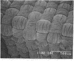
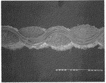
実施例12の人工器官について、表面及び断面の顕微鏡写真を図3及び図4に示す。
実施例1〜14の人工器官の経糸は、経糸α及び経糸βの2種類の太さの糸を用いた。
[Examples 1 to 14]
The warp and the warp adjacent to the warp used were those having a thickness shown in Table 1 in which a plurality of 0.7 denier polyethylene terephthalate monofilaments were twisted, and the weft was a plurality of 0.7 denier polyethylene terephthalate monofilaments. A 100 denier thread was used.
There is one portion where two warp yarns adjacent in the circumferential direction satisfy the relationship of formula (1), warp α is used as the warp of this portion, warp β is used as the adjacent warp, and warp α and warp thereafter. By alternately arranging β, a seam-free tubular plain weave prosthesis as shown in FIG. 1 was produced. The total number of warps is an odd number.
3 and 4 show micrographs of the surface and cross section of the prosthesis of Example 12.
As the warp of the prosthesis of Examples 1 to 14, two types of thicknesses of warp α and warp β were used.
[比較例1]
経糸は、0.7デニールのポリエチレンテレフタレート製モノフィラメントを複数本撚糸した150デニールの糸を用い、緯糸は0.7デニールのポリエチレンテレフタレート製モノフィラメントを複数本撚糸した100デニールの糸を用いて、シームのない管状で平織りの人工器官を作成した。
比較例1の人工器官について、表面及び断面の顕微鏡写真を図5及び図6に示す。
[Comparative Example 1]
The warp is a 150 denier yarn made by twisting a plurality of 0.7-denier polyethylene terephthalate monofilaments, and the weft is a 100-denier yarn made by twisting a plurality of 0.7-denier polyethylene terephthalate monofilaments. Created no tubular, plain weave prosthesis.
5 and 6 show micrographs of the surface and cross section of the prosthesis of Comparative Example 1.
実施例12の断面写真(図4)と比較例1の断面写真(図6)とを比較すると、比較例1の断面に比べ、実施例12の断面は、経糸が満に織られていた。実施例12を除く実施例1〜14の人工器官の断面でも、経糸は全て満に織られていた。
実施例1〜14の人工器官は、全て比較例1の人工器官よりも、柔軟性に優れ、ゼラチンのコーティング処理による目止め性能に優れていた。
実施例1〜14の人工器官及び比較例1の人工器官の人工血管内部からの光の透過を目視で観察した所、実施例1〜14の人工器官では光漏れがなく、比較例1の人工器官では少し光が漏れていた。実施例1〜14の人工器官は比較例1に比べ、目詰効果が大きい。
なお図4及び図6は、人工器官の周方向の断面であり、経糸の配置が理解できる。
Comparing the cross-sectional photograph of Example 12 (FIG. 4) and the cross-sectional photograph of Comparative Example 1 (FIG. 6), the cross-section of Example 12 was fully woven with the warp compared to the cross-section of Comparative Example 1. Even in the cross sections of the prostheses of Examples 1 to 14 except Example 12, all the warp yarns were fully woven.
The prostheses of Examples 1 to 14 were all superior to the prosthesis of Comparative Example 1 in flexibility and excellent sealing performance by the gelatin coating treatment.
The light transmission from the inside of the artificial blood vessel of the artificial organs of Examples 1 to 14 and Comparative Example 1 was visually observed. There was no light leakage in the artificial organs of Examples 1 to 14, and the artificial body of Comparative Example 1 There was a little light leaking in the organ. The prosthetic devices of Examples 1 to 14 have a greater clogging effect than Comparative Example 1.
4 and 6 are cross sections in the circumferential direction of the prosthesis, and the arrangement of the warps can be understood.
1,2,3,4:経糸、10,50:人工血管。
1, 2, 3, 4: Warp, 10, 50: Artificial blood vessel.
Claims (4)
この管状の人工器官の経糸が、
1)周方向に隣接する2本の経糸(経糸A及び経糸B)が式(1)の関係を満たす部分が少なくとも1カ所あり、
2)経糸Bから、周方向に隣接する2本の経糸が式(1)の関係を満たす部分の経糸までの周方向に配列されている経糸において、経糸とそれに隣接する経糸とが、式(2)又は式(3)の関係を満たすように配置されていることを特徴とする人工器官。
The warp of this tubular prosthesis
1) There are at least one portion where two warps adjacent to the circumferential direction (warp A and warp B) satisfy the relationship of formula (1),
2) In a warp in which two warps adjacent in the circumferential direction from warp B are arranged in the circumferential direction from the portion satisfying the relationship of formula (1), the warp and the adjacent warp are expressed by the formula ( A prosthesis characterized by being arranged so as to satisfy the relationship of 2) or formula (3).
この管状の人工器官の経糸が、
1)周方向に隣接する2本の経糸(経糸A及び経糸B)が式(1)の関係を満たす部分が少なくとも1カ所あり、
2)経糸Bから、周方向に隣接する2本の経糸が式(1)の関係を満たす部分の経糸までの周方向に配列されている経糸において、経糸とそれに隣接する経糸とが、式(2)と式(3)の順序、又は式(3)と式(2)の順序で交互に関係を満たすように配置されていることを特徴とする人工器官。
The warp of this tubular prosthesis
1) There are at least one portion where two warps adjacent to the circumferential direction (warp A and warp B) satisfy the relationship of formula (1),
2) In a warp in which two warps adjacent in the circumferential direction from warp B are arranged in the circumferential direction from the portion satisfying the relationship of formula (1), the warp and the adjacent warp are expressed by the formula ( 2. A prosthesis characterized by being arranged so as to satisfy the relationship alternately in the order of 2) and formula (3) or in the order of formula (3) and formula (2).
The part where two warp yarns (warp yarn A and warp yarn B) adjacent in the circumferential direction satisfy the relationship of the formula (1) is owned by one or more odd numbers. The described prosthesis.
Priority Applications (1)
| Application Number | Priority Date | Filing Date | Title |
|---|---|---|---|
| JP2004210322A JP2006026155A (en) | 2004-07-16 | 2004-07-16 | Tubular prosthesis |
Applications Claiming Priority (1)
| Application Number | Priority Date | Filing Date | Title |
|---|---|---|---|
| JP2004210322A JP2006026155A (en) | 2004-07-16 | 2004-07-16 | Tubular prosthesis |
Publications (1)
| Publication Number | Publication Date |
|---|---|
| JP2006026155A true JP2006026155A (en) | 2006-02-02 |
Family
ID=35893167
Family Applications (1)
| Application Number | Title | Priority Date | Filing Date |
|---|---|---|---|
| JP2004210322A Pending JP2006026155A (en) | 2004-07-16 | 2004-07-16 | Tubular prosthesis |
Country Status (1)
| Country | Link |
|---|---|
| JP (1) | JP2006026155A (en) |
Cited By (2)
| Publication number | Priority date | Publication date | Assignee | Title |
|---|---|---|---|---|
| CN102871771A (en) * | 2012-09-04 | 2013-01-16 | 清华大学 | Method for preparing fusiform complicated organ precursor by using rotary assembling die |
| WO2014175301A1 (en) * | 2013-04-26 | 2014-10-30 | 東レ株式会社 | Artificial blood vessel |
-
2004
- 2004-07-16 JP JP2004210322A patent/JP2006026155A/en active Pending
Cited By (4)
| Publication number | Priority date | Publication date | Assignee | Title |
|---|---|---|---|---|
| CN102871771A (en) * | 2012-09-04 | 2013-01-16 | 清华大学 | Method for preparing fusiform complicated organ precursor by using rotary assembling die |
| WO2014175301A1 (en) * | 2013-04-26 | 2014-10-30 | 東レ株式会社 | Artificial blood vessel |
| JPWO2014175301A1 (en) * | 2013-04-26 | 2017-02-23 | 東レ株式会社 | Artificial blood vessel |
| US9943424B2 (en) | 2013-04-26 | 2018-04-17 | Toray Industries, Inc. | Artificial blood vessel |
Similar Documents
| Publication | Publication Date | Title |
|---|---|---|
| US5282846A (en) | Ravel-resistant, self-supporting woven vascular graft | |
| US5178630A (en) | Ravel-resistant, self-supporting woven graft | |
| JP2779456B2 (en) | Self-holding woven artificial blood vessel and method for producing the same | |
| US7105021B2 (en) | Implantable textile prostheses having PTFE cold drawn yarns | |
| US9427342B2 (en) | Woven fabric with shape memory element strands | |
| JPS6037734B2 (en) | Tubular organ prosthesis material and its manufacturing method | |
| JPS59218158A (en) | Blood vessel implant piece having cross structure | |
| Khlif et al. | Contribution to the improvement of textile vascular prostheses crimping | |
| AU7205487A (en) | Vascular prostheses apparatus and method of manufacture | |
| JP2023517573A (en) | Artificial blood vessel and manufacturing method thereof | |
| JP2005261867A (en) | Tubular artificial organ | |
| JP2006026155A (en) | Tubular prosthesis | |
| US10292809B2 (en) | Thoracic graft having yarn modifications | |
| JPH01155860A (en) | Artificial blood vessel | |
| JPH11104153A (en) | Graft for stent | |
| WO2023195397A1 (en) | Artificial blood vessel | |
| US11589975B1 (en) | Small diameter vascular prosthesis | |
| JP2002017758A (en) | Branch artifical blood vessel | |
| WO2023149582A1 (en) | Artificial blood vessel and method for manufacturing artificial blood vessel | |
| WO2022209633A1 (en) | Artificial blood vessel | |
| JPH10328214A (en) | Artificial blood vessel for stent | |
| JPH02220643A (en) | Artificial blood vessel and preparation thereof | |
| JP2003339746A (en) | Woven tubular body for stent type blood vessel prosthesis material, and stent type blood vessel prosthesis material using the same |