JP2006025123A - Image processor - Google Patents
Image processor Download PDFInfo
- Publication number
- JP2006025123A JP2006025123A JP2004200753A JP2004200753A JP2006025123A JP 2006025123 A JP2006025123 A JP 2006025123A JP 2004200753 A JP2004200753 A JP 2004200753A JP 2004200753 A JP2004200753 A JP 2004200753A JP 2006025123 A JP2006025123 A JP 2006025123A
- Authority
- JP
- Japan
- Prior art keywords
- data
- bits
- bit
- pixel
- low
- Prior art date
- Legal status (The legal status is an assumption and is not a legal conclusion. Google has not performed a legal analysis and makes no representation as to the accuracy of the status listed.)
- Pending
Links
Images


Classifications
-
- H—ELECTRICITY
- H04—ELECTRIC COMMUNICATION TECHNIQUE
- H04N—PICTORIAL COMMUNICATION, e.g. TELEVISION
- H04N1/00—Scanning, transmission or reproduction of documents or the like, e.g. facsimile transmission; Details thereof
- H04N1/40—Picture signal circuits
- H04N1/409—Edge or detail enhancement; Noise or error suppression
Abstract
Description
本発明は、デジタルカメラ等の画像処理装置に係り、特には圧縮伸張変換後のS/Nを改善し良好な階調特性が得られるようにした画像処理装置に関する。 The present invention relates to an image processing apparatus such as a digital camera, and more particularly to an image processing apparatus that improves S / N after compression / expansion conversion and obtains favorable gradation characteristics.
近年、デジタルカメラ等の画像入力機器の発達により、画像データの取り込みが高精度になった。また、高精度に取り込んだ画像データを記憶装置に記憶し、パーソナルコンピュータ等でユーザは画像データを簡単にモニタ、プリンタ等の出力装置に出力できる。 In recent years, with the development of image input devices such as digital cameras, image data capture has become highly accurate. Further, the image data captured with high accuracy is stored in a storage device, and the user can easily output the image data to an output device such as a monitor or a printer using a personal computer or the like.
画像データを記憶する場合、画像データは、1画素当り12ビット〜14ビットのデジタル信号として記憶される場合がある。例えば、12ビットであれば階調数は、「4096」である。このように12ビット〜14ビットで高精度に取り込まれた画像データは、非圧縮もしくは可逆圧縮を行った後に、記憶媒体に保存される。 When storing image data, the image data may be stored as a digital signal of 12 to 14 bits per pixel. For example, if it is 12 bits, the number of gradations is “4096”. Thus, the image data captured with high precision at 12 to 14 bits is stored in a storage medium after being subjected to non-compression or lossless compression.
ここで、1画素当り12ビットの画像データをそのまま記憶したのでは、データ量が膨大となるため、画素データを圧縮処理した後、記憶媒体に記憶するようにしている。
このような、デジタルカメラ等の画像入力装置で撮影した画像を記録する方式において、画素データの下位ビットは撮像系のノイズなどであることを見越して、切捨てる方式がある。下位ビットの切捨て方法は全画素一様に切捨てる方法や、ノイズ量を考慮して切捨てる下位ビットを逐一変更する方法が存在する。
Here, if image data of 12 bits per pixel is stored as it is, the amount of data becomes enormous. Therefore, the pixel data is compressed and stored in a storage medium.
In such a method of recording an image taken by an image input device such as a digital camera, there is a method of truncating in anticipation that the lower bits of pixel data are noise of the imaging system. There are two methods for truncating the lower bits: a method of discarding all pixels uniformly, and a method of changing the lower bits to be discarded one by one in consideration of the amount of noise.
特許文献1では、有効なデータの値に対応するビット数を利用し、下位ビットで切捨て、ビット数を画素ごとに設定する方法(上位ビットとの相関を取る方法)が開示されている。
しかしながら、下位ビットの切捨てによって作成された圧縮データを、伸張した後に画像処理を行う場合、ビット切捨てによって減少した階調数で画像処理を行うため、切捨てしない場合と比較して、画像のエッジ部や階調変化部に対して不自然なレベルの変化(トーンジャンプ)が発生する。 However, when image processing is performed after decompressing compressed data created by truncating lower bits, image processing is performed with the number of gradations reduced by bit truncation. Or an unnatural level change (tone jump) occurs in the gradation changing portion.
本発明は上記のような実情に鑑みてなされたものであり、記憶時に撮像系の雑音成分等として、一様に下位ビットが切捨てられた圧縮画像データを伸張し、伸張データをビットシフトした後に、伸張した画素データを補正するための下位ビットのデータを算出し、切捨てられた成分(下位ビット)の換わりとすることで、画像のエッジや階調の不連続性を除去し、さらにS/Nを改善し良好な階調特性が得られるようにする画像処理装置を提供することを目的とする。 The present invention has been made in view of the above-described circumstances, and after decompressing compressed image data in which lower-order bits are uniformly cut off as a noise component of an imaging system at the time of storage and bit-shifting the expanded data By calculating lower bit data for correcting the expanded pixel data and substituting the truncated component (lower bit), the image edge and gradation discontinuity are removed, and S / An object of the present invention is to provide an image processing apparatus that can improve N and obtain good gradation characteristics.
請求項1記載の発明は、画像データを構成する1以上の参照画素データに基づいて注目画素データの下位ビットを予測する画像処理装置において、前記画像データを構成する1以上の前記参照画素データに基づいて前記注目画素データの下位ビットを算出して補正下位ビットとする下位ビット算出手段と、前記下位ビット算出手段より求めた前記補正下位ビットと前記注目画素データとを加算する手段と、を具備することを特徴とする。 According to the first aspect of the present invention, in the image processing apparatus that predicts the lower bits of the target pixel data based on the one or more reference pixel data constituting the image data, the one or more reference pixel data constituting the image data Low-order bit calculation means for calculating a low-order bit of the pixel-of-interest data based on the low-order bit as a corrected low-order bit; It is characterized by doing.
請求項2記載の発明は、前記参照画素データの上位ビットに基づいて、前記注目画素データの下位ビットを算出して前記補正下位ビットとすることを特徴とする。
請求項3記載の発明は、前記下位ビット算出手段により、前記参照画像データの値に対し重み付け係数を決定し、前記重み付け係数と前記注目画素データの上位ビットを乗算し前記補正下位ビットを算出することを特徴とする。
The invention according to
According to a third aspect of the present invention, the lower-order bit calculation means determines a weighting coefficient for the value of the reference image data, and calculates the corrected lower-order bit by multiplying the weighting coefficient by the higher-order bit of the target pixel data. It is characterized by that.
請求項4記載の発明は、前記下位ビット算出手段により、前記注目画素データの近傍の前記参照画素データにより画素値の相関を求め、前記相関の結果に基づいて前記補正下位ビットを算出することを特徴とする。 According to a fourth aspect of the present invention, the lower bit calculation means obtains a correlation between pixel values based on the reference pixel data in the vicinity of the target pixel data, and calculates the corrected lower bit based on the correlation result. Features.
請求項5記載の発明は、前記下位ビット算出手段により、前記注目画素の両隣の前記参照画素の上位ビットを利用し、前記両隣の前記参照画素上位ビットデータの画素値の平均を算出することにより前記相関を求めることを特徴とする。 In the fifth aspect of the present invention, the lower bit calculation means uses the upper bits of the reference pixels on both sides of the target pixel, and calculates the average of the pixel values of the reference pixel upper bit data on both sides. The correlation is obtained.
請求項6記載の発明は、前記下位ビット算出手段により、前記注目画素の周辺の前記参照画素の上位ビットを利用し、前記周辺の前記参照画素の上位ビットデータの画素値の平均を算出することにより前記相関を求めることを特徴とする。 According to a sixth aspect of the present invention, the lower bit calculation means uses an upper bit of the reference pixel around the pixel of interest to calculate an average of pixel values of upper bit data of the peripheral reference pixel. To obtain the correlation.
請求項7記載の発明は、前記注目画素の下位ビット算出手段により、前記注目画素の近傍の原色ベイヤ配列における異色成分の前記参照画素の上位ビットに基づいて第1の色成分相関を算出し、さらに前記第1の色成分相関の結果と前記参照画素の上位ビットに基づいた第2の色成分相関により前記補正下位ビットを算出することを特徴とする。 The invention according to claim 7 calculates the first color component correlation based on the upper bits of the reference pixel of the different color component in the primary color Bayer array in the vicinity of the target pixel by the lower bit calculation unit of the target pixel, Further, the corrected lower bit is calculated by a second color component correlation based on the result of the first color component correlation and the upper bit of the reference pixel.
請求項8記載の発明は、前記下位ビット算出手段により、前記画像データ全体の前記参照画素の上位ビットを利用した相関に基づく関数を算出し前記第1の色成分相関を求めることを特徴とする。 The invention according to claim 8 is characterized in that the lower-order bit calculation means calculates a function based on a correlation using higher-order bits of the reference pixels of the entire image data to obtain the first color component correlation. .
請求項9記載の発明は、前記下位ビット算出手段により、前記画像データを分割し、前記分割したブロック毎に前記参照画素の上位ビットを利用した相関に基づき関数を算出し前記第1の色成分相関を求めることを特徴とする。 According to a ninth aspect of the present invention, the image data is divided by the lower bit calculation means, a function is calculated based on a correlation using upper bits of the reference pixel for each of the divided blocks, and the first color component is calculated. The correlation is obtained.
請求項10記載の発明は、前記下位ビット算出手段により、前記第1の色成分相関により算出した値により予め用意したテーブルを利用して前記補正下位ビットを算出することにより前記第2の色成分相関を求めることを特徴とする。 According to a tenth aspect of the present invention, the second color component is calculated by calculating the corrected lower bit by using the table prepared in advance by the value calculated by the first color component correlation by the lower bit calculation means. The correlation is obtained.
請求項11記載の発明は、画像データを構成する1以上の画素データに基づいて前記画素データの下位ビットを予測する画像処理をコンピュータに実行させるプログラムであって、前記画像データを構成する1以上の前記参照画素データに基づいて前記注目画素データの下位ビットを算出して補正下位ビットとする下位ビット算出機能と、前記下位ビット算出機能より求めた前記補正下位ビットと前記注目画素の上位ビットとを加算する加算機能と、をコンピュータに実現させるためのプログラム。
The invention according to
請求項12記載の発明は、前記参照画素データの上位ビットに基づいて、前記注目画素データの下位ビットを算出して前記補正下位ビットとすることをコンピュータに実現させるためのプログラム。 The invention according to claim 12 is a program for causing a computer to calculate a lower bit of the pixel-of-interest data based on an upper bit of the reference pixel data and use it as the corrected lower bit.
上記により、下位ビットを切捨てた画像データに対し、補正した下位ビットを加算(重畳)することで階調数を増やすことができる。それにより圧縮・伸張等の画像処理を施した画像において、画像のエッジや階調の不連続性を除去し、S/Nを改善し良好な階調特性が得られるようにし、不自然なレベルの変化(トーンジャンプ)の発生を防止できる。 As described above, the number of gradations can be increased by adding (superimposing) the corrected lower bits to the image data with the lower bits cut off. As a result, in images that have been subjected to image processing such as compression / expansion, image edges and gradation discontinuities are removed, S / N is improved, and good gradation characteristics are obtained. Can be prevented from occurring (tone jump).
(実施形態1)
以下、本発明の実施の形態を図面に基づいて説明する。図1は、本発明を実施するデジタルカメラの構成を示す図である。尚、本実施例では、デジタルカメラを例とするが、デジタルカメラに限定されるものではない。
(Embodiment 1)
Hereinafter, embodiments of the present invention will be described with reference to the drawings. FIG. 1 is a diagram showing the configuration of a digital camera that implements the present invention. In this embodiment, a digital camera is taken as an example, but the present invention is not limited to a digital camera.
CPU(Central Processing Unit )−A1はこのデジタルカメラ全体の動作制御を行う中央演算装置である。EEPROM(Electrically Erasable and Programmable Read Only Memory)2は、デジタルカメラの動作制御をCPU−A1に行なわせるための制御プログラムが予め格納されており、CPU−A1はこの制御プログラムを実行することによって上述した動作制御を行うようになる。 A CPU (Central Processing Unit) -A1 is a central processing unit that controls the operation of the entire digital camera. An EEPROM (Electrically Erasable and Programmable Read Only Memory) 2 stores a control program for causing the CPU-A1 to control the operation of the digital camera in advance, and the CPU-A1 executes the control program as described above. Operation control is performed.
レンズ3は被写体像をCCD4に結像させる撮影光学系である。CCD(Charge Coupled Device )4は結像された被写体像を光電変換して画像を示す電気信号(アナログ信号)を出力する撮像素子である。撮像回路5は、CDS(Correlated Double Sampling:相関二重サンプリング回路)やAGC(Automatic Gain Control:オートゲインコントロール回路)等を含んで構成され、CPU−A1の制御の下に、CCD4から出力された電気信号(アナログ信号)に含まれ得るリセット雑音の除去や信号レベルの調節などを行う回路である。
The
A/D変換部6は、撮像回路5の出力信号(アナログ信号)をデジタルデータに変換する回路である。補正回路7は、A/D変換部6から出力されるデジタルデータで表現されている撮影画像に、ホワイトバランスやY補正等の補正処理を施す回路である。
The A / D converter 6 is a circuit that converts an output signal (analog signal) of the
補正回路7の出力は、フレームメモリ8、CPU−B9、FIFOメモリ10、及び記録媒体I/F11とバス12を介して接続されており、これらの間ではCPU−B9によるバス12の管理の下で相互にデータの授受を行うことができる。
The output of the correction circuit 7 is connected to the frame memory 8, CPU-B 9,
フレームメモリ8は、補正回路7から出力された撮影画像やCPU−B9により画像処理が施された撮影画像などを一時的に蓄えるバッファメモリとして使用される他、CPU−B9による各種処理のための作業用の記憶領域としても使用されるメモリである。 The frame memory 8 is used as a buffer memory for temporarily storing a photographed image output from the correction circuit 7 or a photographed image subjected to image processing by the CPU-B9, and for various processing by the CPU-B9. This memory is also used as a work storage area.
CPU−B9は、CPU−A1の制御の下で、自己の内部に備えられた制御プログラムに従い、フレームメモリ8の管理(フレームメモリコントロール機能)、圧縮されている画像データの伸張処理(画像伸張機能)、撮影画像に対するデータ圧縮処理(画像圧縮機能)、及びデータの書き込み及び読み出しのための記録媒体21へのアクセスの制御処理(記録媒体アクセス機能)などを行う。なお、画像データの圧縮処理及び伸張処理では、例えばJPEG(Joint Photographic Experts Group)方式による圧縮処理及び伸張処理等が行われる。
Under the control of the CPU-A1, the CPU-B9 manages the frame memory 8 (frame memory control function) and decompresses the compressed image data (image decompression function) in accordance with a control program provided therein. ), Data compression processing (image compression function) for the captured image, and control processing (recording medium access function) of access to the
FIFO(First-In First-Out)メモリ10は表示を行う画像を表現する画像データを一時的に格納するメモリであり、CPU−B9により画像処理された後の画像データなどが格納される。記録媒体I/F11は、記録媒体13との間でデータの授受を行うためのインタフェース機能を提供するものであり、記録媒体13へのデータの書き込み、或いは記録媒体13からのデータの読み出しの処理が行われる。
A first-in first-out (FIFO)
記録媒体13は記録されたデータを保持するものであり、半導体メモリが内蔵されているメモリカードなどのリムーバブル型の記録媒体がデジタルカメラには便利である。ビデオエンコード回路14は、CPU−A1の制御の下で、FIFOメモリ10から読み出されたデータで表現される画像に日付等のオンスクリーン情報を重畳させる回路である。
The
ビデオ出力回路15は、ビデオエンコード回路14から出力されたデジタル画像データをアナログ信号であるビデオ信号(画像信号)へと変換する回路である。ビデオ出力端子16は、ビデオ出力回路15から出力されたビデオ信号をこのデジタルカメラの外部へと出力する端子である。
The
TFT(Thin Film Transistor)液晶駆動回路17は、CPU−A1の制御の下で、ビデオエンコード回路14から出力された画像信号に基づいてTFTパネル18を駆動する回路である。TFTパネル(TFT液晶パネル)18はTFT液晶駆動回路17によって駆動されてビデオエンコード回路14から出力された画像信号で表現される画像を表示する液晶モニタとして用いられている。
A TFT (Thin Film Transistor) liquid
なお、このデジタルカメラでは光学ファインダ(不図示)が装備されており、CCD4に結像している被写体像を液晶モニタに表示させずに被写体像の撮影をすることが可能であるので、このデジタルカメラに液晶モニタを動作させるか否かをユーザが設定できる構成としている。ここで、液晶モニタを動作させないように設定すればこのデジタルカメラの通常動作時における消費電力を低減させることができる。
Since this digital camera is equipped with an optical viewfinder (not shown), the subject image formed on the
バックライトユニット19はTFTパネル18と一体となって液晶モニタを構成するものであり、CPU−A1の制御の下にTFTパネル18の液晶部をその背面から照射する光源が設けられているユニットである。この光源としては例えば白色LED(Light Emitting Diode )などが用いられる。
The
アクチュエータ20は、レンズ(撮影光学系)3を駆動させるためのモータ(AF用モータやズーミング用モータ等)や機械式のシャッタの駆動装置などといった作動装置であり、アクチュエータ駆動回路21で駆動される。アクチュエータ駆動回路21は、CPU−A1の制御の下でアクチュエータ20を駆動させる回路である。
The
外部データI/F22は、パーソナルコンピュータ等の外部装置とCPU−A1との間でのデータの授受を行うためのインタフェース機能を提供するものであり、例えばUSB(Universal Serial Bus)方式のI/Fである。キーマトリクス部23は、ユーザからの各種指示を受け付け、それをCPU−A1へ通知するための各種キー、スイッチ、ボタン等をマトリクス状に配線したものである。画像の撮影動作をこのデジタルカメラに行なわせるために操作されるレリーズボタンもこのキーマトリクス部23に含まれており、CPU−A1は、レリーズボタンに対する1stレリーズ(いわゆる半押し)及び2ndレリーズ(いわゆる全押し)の操作を検出することができる。
The external data I /
LCD表示回路24は、CPU−A1の制御の下でLCDパネル25を駆動する回路である。LCDパネル25は、LCD表示回路24により駆動され、その駆動信号に応じた表示、例えば、露出やシャッタースピードなどといったこのデジタルカメラについての各種の設定状態の表示や、現在において撮影及び記録が可能である画像の枚数を示す表示を行う。
The
電池26はこのデジタルカメラへ電力を供給するための電源である。電源回路27は、電池26から供給される電圧を制御してデジタルカメラの各部に電力を供給する回路である。CPU−A1は電源回路27に電力を供給している電池26の電圧の監視を行なっており、このデジタルカメラが通常の動作を行なっているとき(電源オン時)にその電圧値が一時的にでも所定値よりも小さくなったならばCPU−A1はその後このデジタルカメラでの撮影動作を禁止し、レリーズボタンに対する操作が行なわれても撮影のための制御処理を行わない。
The
ここで、CPU−A1、フレームメモリ8、CPU−B9、TFT液晶駆動回路17、TFTパネル18等は一般的なパーソナルコンピュータを利用してもかまわない。
また、後述する処理はコンピュータプログラムにより処理可能で、その処理プログラムはCD−ROM等記録媒体やハードディスク等に記録されている。必要に応じて前記パーソナルコンピュータのメモリ上に前記処理プログラムを読み出し、CPUで実行しパーソナルコンピュータに接続されている各装置を制御している。
Here, the CPU-A1, the frame memory 8, the CPU-B9, the TFT liquid
The processing described later can be processed by a computer program, and the processing program is recorded on a recording medium such as a CD-ROM, a hard disk, or the like. If necessary, the processing program is read onto the memory of the personal computer and executed by the CPU to control each device connected to the personal computer.
なお、記録媒体は通信回線を介してコンピュータと接続されている、プログラムサーバとして機能するコンピュータが備えている記憶装置であってもよい。
この場合には、制御プログラムを表現するデータ信号で搬送波を変調して得られる伝送信号を、プログラムサーバから伝送媒体である通信回線を通じてコンピュータヘ伝送するようにし、コンピュータでは受信した伝送信号を復調して処理プログラムを再生することでこの処理プログラムをCPUで実行できるようになる。
(実施例1)
次に、上記構成を説明したデジタルカメラにおける、本発明の画像処理について説明をする。本実施例では、上位ビットとの相関を利用する方法として、上位ビットa(10ビット)と下位ビットb(2ビット)より構成される12ビットの画素データの処理について説明する。
The recording medium may be a storage device provided in a computer functioning as a program server connected to the computer via a communication line.
In this case, a transmission signal obtained by modulating a carrier wave with a data signal representing a control program is transmitted from a program server to a computer through a communication line as a transmission medium, and the computer demodulates the received transmission signal. By replaying the processing program, the processing program can be executed by the CPU.
Example 1
Next, the image processing of the present invention in the digital camera having the above configuration will be described. In the present embodiment, processing of 12-bit pixel data composed of upper bits a (10 bits) and lower bits b (2 bits) will be described as a method of using correlation with upper bits.
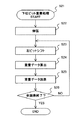
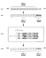
図2、図3は画像処理を行うときの概略フローで、撮像系の雑音成分として1画素の示すデータのビットのうち下位ビット分を切捨てた画素データとして記憶された画像に、算出した下位ビット(補正下位ビット)を重畳データとして、切捨てられた成分(下位ビット)の換わりに加算(重畳)することを示している。 FIG. 2 and FIG. 3 are schematic flows when performing image processing. The calculated lower bits are stored in the image stored as pixel data obtained by discarding the lower bits of the data bits indicated by one pixel as noise components of the imaging system. This indicates that (corrected lower bit) is added (superimposed) instead of the truncated component (lower bit) as superposed data.
図2のフローについて説明する。
ステップS21は、下位ビット重畳処理の開始で、S21に進む以前に下位ビット分を切捨て圧縮された画素データがS21に渡される。
The flow of FIG. 2 will be described.
In step S21, the lower-order bit superimposing process is started, and the pixel data obtained by rounding down and compressing the lower-order bits before proceeding to S21 is passed to S21.
ステップS22では、圧縮データを伸張し、ステップS23で、切捨てた下位ビット分だけ、左側にビットシフトを行う。
次に、ステップS24で、下位ビットに重畳する重畳データを算出し、ステップS25で重畳データを加算する。
In step S22, the compressed data is decompressed, and in step S23, a bit shift is performed to the left by the discarded lower bits.
Next, in step S24, superimposition data to be superimposed on the lower bits is calculated, and in step S25, the superposition data is added.
全ての画素に対してS23〜S25の処理を行い、ステップS26の判断で全ての画素に処理をしていればYESに進み終了する。NOであればS23〜S25の処理を再度行う。 The processing of S23 to S25 is performed for all the pixels, and if all the pixels are processed in the determination of step S26, the process proceeds to YES and ends. If NO, the processes of S23 to S25 are performed again.
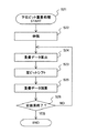
図3は図2の処理を入れかえた変形例である。図3のフローについて説明すると、ステップS21、ステップS22、ステップS26は、図2と同様の処理を行い、ステップS23〜S25の処理の順番を入れかえたフローである。 FIG. 3 shows a modification in which the process of FIG. 2 is replaced. The flow of FIG. 3 will be described. Steps S21, S22, and S26 are flows in which processing similar to that in FIG. 2 is performed and the order of processing in steps S23 to S25 is changed.
図3ではステップS24を先に処理し、下位ビットに重畳する重畳データを算出する。次にステップS23で、切捨てた下位ビット分を左側にビットシフトを行う。そして、ステップS25で重畳データを加算する。よって、図3の結果は、図2のフローの結果と同様となる。 In FIG. 3, step S24 is processed first to calculate superimposition data to be superimposed on the lower bits. Next, in step S23, the discarded lower bits are bit shifted to the left. In step S25, the superimposed data is added. Therefore, the result of FIG. 3 is the same as the result of the flow of FIG.
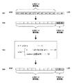
次に、図4、図5を用いてより詳細な説明をすると、図4は、上位ビットa(10ビット)と下位ビットb(2ビット)より構成される12ビットの画素データをCPU−B9に取り込み、画像圧縮機能で下位ビットbを切捨て10ビットのデータに変更する。その後、圧縮処理をし、画素データを記憶する。ここまでが上記ステップS21の処理である。 Next, in more detail with reference to FIG. 4 and FIG. 5, FIG. 4 shows that 12-bit pixel data composed of upper bits a (10 bits) and lower bits b (2 bits) is CPU-B9. And the lower-order bit b is truncated and changed to 10-bit data by the image compression function. Thereafter, compression processing is performed, and pixel data is stored. The processing up to this point is the processing in step S21.
次に、図5は画像データを出力する場合、TFTパネル18に画像データを表示するときなどに、上記S21によって圧縮処理して記憶したデータを呼び出し、CPU−B9の伸張処理により伸張し10ビットのデータに変換し、上位ビットaを2ビットシフトし、S24で算出した重畳データを下位2ビットに重畳し12ビット幅のデータを生成する。
Next, FIG. 5 shows that when outputting image data, when displaying the image data on the
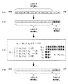
次に、S24について算出する重畳データについて説明する。本実施例1では、算出方法をランダム成分の重畳データとしたときの下位ビットに重畳する方法について図6で説明する。 Next, the superimposed data calculated for S24 will be described. In the first embodiment, a method of superimposing on lower bits when the calculation method is the superimposition data of random components will be described with reference to FIG.
S61は、圧縮時に切捨てられた10ビット幅の画素データを伸張したものを左に2ビットシフトした図である。S61でビットシフトすることで2ビットMSB側に移動する。 S61 is a diagram obtained by shifting the decompressed 10-bit pixel data truncated at the time of compression by 2 bits to the left. The bit shift is performed in S61 to move to the 2-bit MSB side.
次に、S62で下位2ビットであるb0、b1の場所に0を重畳する。ここではb0、b1をともに0としている。
S63では、S63の式1により下位ビットbを算出する。まず、上位ビットaを比較することでω(a)を算出する。S63の式2は上位ビットaが0もしくは1であれば、圧縮時に切捨てた下位ビットをともに0にする。
Next, in S62, 0 is superimposed on the lower 2 bits b0 and b1. Here, both b0 and b1 are 0.
In S63, the lower bit b is calculated by
S63の式3は上位ビットaが0以外であるとき、ランダムに重畳データを選ぶ。このとき下位ビットbが2ビットであればω(a)は、00、01、10、11の値を選び、S63の式1のb=ω(a)・aを計算し、乗算された12ビットのデータの下位2ビットをbとする。尚、bは2ビットであれば上位2ビットを選択してもいいし、12ビットのどのデータを選んでもかまわない。
S64で、S63で算出した下位ビットbを重畳データとして上位ビットaに重畳する。
図7は図6のS61〜S64を実行させるブロックを示した図である。伸張部71によって切捨てされた10ビットの画素データを伸張し、次にビットシフト部72でS61とS62の処理を行い、データ保持用メモリ73にはS62の結果を保持する。
In S64, the lower bit b calculated in S63 is superimposed on the upper bit a as superimposed data.
FIG. 7 is a diagram showing blocks for executing S61 to S64 of FIG. The 10-bit pixel data truncated by the
そして、データ比較部74ではS63の条件に従い上位ビットaに基づきω(a)を算出する。重畳データ算出部75でS63の式1を計算し下位ビットbを算出する。算出後、S64に示した動作を行う。つまり、重畳データとデータ保持用メモリに記憶した10ビットの左シフト画素データを加算し12ビットの画素データを生成する。
Then, the
次に、図8を用いて上記構成の説明をフローに基づき行う。
ステップS81では、画素データを圧縮するときに、下位ビット切捨てを行ったかを判断する。切捨てを行っていた場合はS82に進み、切捨てをしていない場合にはS83に進む。このとき、切捨てを行ったかを判断するための情報は、圧縮時に切捨てビット数などの圧縮情報の一部として記憶してありこの情報を参照して判断を行う。尚、圧縮時の切捨下位ビット数をどうするかは、ユーザが選択してもいいし、全画像の画像状態などに基づき条件を決め、その条件に基づき自動で選択されてもかまわない。
Next, the above configuration will be described based on the flow with reference to FIG.
In step S81, it is determined whether lower bit truncation has been performed when the pixel data is compressed. If truncation has been performed, the process proceeds to S82, and if truncation has not been performed, the process proceeds to S83. At this time, information for determining whether or not truncation has been performed is stored as a part of the compression information such as the number of bits to be discarded during compression, and the determination is performed with reference to this information. It should be noted that the user may select how to reduce the number of bits to be cut off at the time of compression, or the condition may be determined based on the image state of all the images and automatically selected based on the condition.
ステップS82では、圧縮時に決めた切捨てビット数を読込み、ステップS83では、切捨てをしなかったので切捨てビット数を0にしている。
ステップS84では、下位ビットbを切捨てされ圧縮されている1画像に含まれる画素データ全てを伸張し、圧縮前の切捨てされた画素データ(10ビット)に変換する。
In step S82, the number of truncation bits determined at the time of compression is read. In step S83, the truncation bit number is set to 0 because no truncation is performed.
In step S84, all the pixel data included in one image that has been compressed with the lower-order bits b rounded down are decompressed and converted into the truncated pixel data (10 bits) before compression.
ステップS85では、S84で伸張したデータを読込み、ステップS86で、上記切捨てビットが0であるかないかを判断し、YESであれば、下位ビットの重畳処理をしないでS811に進む。NOであれば、ステップS87に進み、切捨てビット分左にビットシフトする。 In step S85, the data decompressed in S84 is read. In step S86, it is determined whether or not the truncation bit is 0. If YES, the process proceeds to S811 without performing the lower bit superimposition process. If NO, the process proceeds to step S87, and a bit shift is made to the left by the cut bits.
次に、ステップS88で、S87で左ビットシフトデータの上位ビットaが0、1もしくはそれ以外であるかを判断し、0、1であればYESでS811に進む。NOであればステップS89に進み、上記S63の条件に従い、ω(a)の値として00、01、10、11を選び、S63の式1を計算し下位ビットbを算出する。そして、ステップS810で上位ビットaと下位ビットbを加算することで重畳する。
Next, in step S88, it is determined in S87 whether the upper bit a of the left bit shift data is 0, 1, or otherwise. If it is 0, the process proceeds to S811 with YES. If NO, the process proceeds to step S89, and according to the condition of S63, 00, 01, 10, and 11 are selected as the values of ω (a),
ステップS811では必要な全ての画素データの処理が終了したかを判断し、全ての処理が終了していればYESに進み終了する。終わっていなければNOに進みS85から再度処理を行う。 In step S811, it is determined whether processing of all necessary pixel data has been completed. If all processing has been completed, the process proceeds to YES and ends. If not completed, the process proceeds to NO, and the process is performed again from S85.
尚、本実施例では下位ビットbを算出する場合、ω(a)・aとしているが、ω(a)の値を直接bとして下位ビットに重畳してもかまわない。
本実施例では、画素データのビット幅を12ビットとし、上位ビット10ビット、下位ビット2ビットの構成としたが、この構成に限定されるものではなく、画像のエッジや階調の不連続性を除去し、さらにS/Nを改善し良好な階調特性が得られるようにする画像処理ができる範囲であれば変形することが可能である。
In this embodiment, when the lower bit b is calculated, ω (a) · a is used. However, the value of ω (a) may be directly set as b and superimposed on the lower bit.
In this embodiment, the bit width of the pixel data is 12 bits, the upper bit is 10 bits, and the lower bit is 2 bits. However, the present invention is not limited to this configuration. Can be modified as long as image processing can be performed so as to remove S, improve S / N, and obtain good gradation characteristics.
例えば、画像データ内において出現頻度の高い値の付近に対してのみランダムに重み付けを与え、その他の部分に対してのは0で重み付けすることも可能である。
尚、ランダム値と固定値を重み付け係数として用いて、対象の画素データ積算して、切捨てした下位ビットの幅の下位ビットを生成し、加算することで、画像のエッジや階調の不連続性を除去し、S/Nを改善することが可能になる。
(実施例2)
次に、実施例2では、隣接する色成分との相関を利用する方法として、上位ビットan(10ビット)と下位ビットcn(2ビット)より構成される12ビットの画素データの処理について説明する。
For example, it is possible to give a weight to only the vicinity of a value having a high appearance frequency in the image data, and to weight the other parts with 0.
In addition, by using the random value and fixed value as the weighting coefficient, the target pixel data is integrated, and the lower bits of the lower bit width are generated and added, thereby adding to the image edge and gradation discontinuity. And S / N can be improved.
(Example 2)
Next, in the second embodiment, as a method of using the correlation with adjacent color components, processing of 12-bit pixel data including upper bits a n (10 bits) and lower bits c n (2 bits) is performed. explain.
図9は、ベイヤ配列された隣接画素を示した図である。隣接する色成分との相関を利用しanの画素の下位ビットcnを決めるために、隣接する左隣接画素の上位ビットan-1、右隣接画素の上位ビットan+1の画素データの相関に基づき下位ビットcnを算出し決定する。 FIG. 9 is a diagram illustrating adjacent pixels arranged in a Bayer array. In order to determine the lower bit c n of the pixels using the correlation with adjacent color components a n, higher-order bits a n-1 of the left neighboring pixels adjacent, higher-order bits a n + 1 of the pixel data of the right adjacent pixels calculating a lower bit c n on the basis of the correlation to be determined.
図10を用いて、隣接する色成分との相関から下位ビットcnを算出する方法を説明する。
S101は、圧縮時に切捨てられた10ビット幅の切捨てされた画素データを伸張したものを左に2ビットシフトした図である。S101でビットシフトすることで2ビットMSB側に移動する。次に、S102で下位2ビットであるb0、b1をともに0とする。ここではb0、b1をともに0としている。
With reference to FIG. 10, illustrating a method for calculating the lower-order bits c n from the correlation between the adjacent color components.
S101 is a diagram obtained by shifting a 10-bit width truncated pixel data that was truncated at the time of compression to the left by 2 bits. The bit shift is performed in S101 to move to the 2-bit MSB side. Next, in S102, b0 and b1, which are the lower 2 bits, are both set to 0. Here, both b0 and b1 are 0.
S103では、S103の式1によりbnを算出する。まず、隣接する画素データの上位ビット(10ビットの画素データ)であるan-1とan+1を用いてbn=(an-1+an+1)/2を算出する。そして、S103の式2〜式5を参照してbnの結果より条件を満たす値を判断しcnを決定する。
In S103, b n is calculated according to
S103の式2は、bnと予め設定された閾値1(k1)と比較し、bn>k1であればcnを3(〔b0〕〔b1〕→〔1〕〔1〕)にする。
S103の式3は、bnと予め設定された閾値1(k1)、閾値2(k2)と比較し、k2<bn<k1であればcnを2(〔b0〕〔b1〕→〔1〕〔0〕)にする。
S103の式4は、bnと予め設定された閾値2(k2)、閾値3(k3)と比較し、k3<bn<k2であればcnを1(〔b0〕〔b1〕→〔0〕〔1〕)にする。
S103の式5は、bnと予め設定された閾値3(k3)と比較し、bn<k3であればcnを0(〔b0〕〔b1〕→〔0〕〔0〕)にする。
次に、S103で決定した重畳データである補正下位ビットcnを、S104で画素データの下位ビットにcnを重畳する。
ここで、予め設定された閾値k1、k2、k3は、両隣の上位ビットの平均値の最大値(上位ビット全て1)から最小値(上位ビット全て0)の範囲で設定される。利用者が好みの画像になるように設定してもかまわない。
Next, the correction lower-order bits c n is a superimposed data determined in S103, superimposing a c n lower bits of the pixel data in S104.
Here, the preset threshold values k 1 , k 2 , and k 3 are set in a range from the maximum value (all upper bits are all 1) to the minimum value (all upper bits are all 0) of the upper bits on both sides. It is possible to set the image so that the user likes it.
図11は図10のS101〜S104を実行させるブロックを示した図である。伸張部111によって圧縮の際に切捨てされた10ビットの画素データを伸張する。次にビットシフト部112でS101とS102の処理を行い、データ保持用メモリ113にはS102の結果を保持し、平均算出部114では隣接画素データ用メモリ115に記憶されているan-1とan+1を呼び出し、S103の式1に従いbnを算出する。そして重畳データ算出部116でS103の式2〜5の条件によってcnを決定する。算出後、S104に示した動作により重畳データとデータ保持用メモリに記憶した10ビットの左シフト画素データanを加算し12ビットの画素データを生成する。
FIG. 11 is a diagram showing blocks for executing S101 to S104 of FIG. The decompressing unit 111 decompresses the 10-bit pixel data that has been discarded during compression. Next, the
次に、図12を用いてフローの説明をする。
ステップS121では、画素データを圧縮するときに、下位ビットの切捨てを行ったかを判断する。このとき、切捨てを行ったかを判断するための情報は、圧縮時に切捨てビット数などの圧縮情報の一部として記憶してありこの情報を参照して判断を行う。尚、切捨てを行っていた場合はS122に進み、切捨てをしていない場合にはS123に進む。圧縮時の切捨て下位ビット数をどうするかは、ユーザが選択してもいいし、画像条件に基づき自動選択されてもかまわない。
Next, the flow will be described with reference to FIG.
In step S121, it is determined whether or not lower bits have been truncated when the pixel data is compressed. At this time, information for determining whether or not truncation has been performed is stored as a part of the compression information such as the number of bits to be discarded during compression, and the determination is performed with reference to this information. If truncation has been performed, the process proceeds to S122, and if truncation has not been performed, the process proceeds to S123. The user can select how the lower-order bits to be cut off at the time of compression are selected, or may be automatically selected based on image conditions.
ステップS122では、圧縮時に決めた切捨てビット数を読込み、ステップS123では、圧縮のときに切捨てをしなかったので切捨てビット数を0にしている。
ステップS124は、圧縮データを伸張し、切捨てされたデータに変換する。
In step S122, the number of truncation bits determined at the time of compression is read. In step S123, the truncation bit number is set to 0 because truncation was not performed at the time of compression.
In step S124, the compressed data is decompressed and converted into truncated data.
ステップS125では、切捨てされたデータを読込み、ステップS126で上記切捨てビットが0であるかないかを判断し、YESであれば、下位ビットの重畳処理をしないでS1212に進む。NOであれば、ステップS127に進み、切捨てビット分左にビットシフトする。 In step S125, the truncated data is read, and in step S126, it is determined whether or not the truncated bit is 0. If YES, the process proceeds to S1212 without performing the superimposition processing of the lower bits. If NO, the process proceeds to step S127, and a bit shift is made to the left by the cut bits.
次に、ステップS128で、S103の式1を計算し隣接画素データan-1とan+1より平均を、bn=(an-1+an+1)/2で算出する。
次に、ステップS129で上記S103の式2〜5の条件に従い、ステップS1210でcnの値(0、1、2、3)を選び、そして、ステップS1211で上位ビットanと下位ビットcnを加算することで重畳する。
Next, in step S128,
Then, in accordance with the conditions of formula 2-5 above S103 in step S129, to select the values of c n (0, 1, 2, 3) in step S1210, and the upper bits a n and a lower bit c n in step S1211 Are superimposed.
ステップS1212では必要な全ての画素データの処理が終了したかを判断し、全ての処理が終了していればYESに進み終了する。終わっていなければNOに進みS125から再度処理を行う。 In step S1212, it is determined whether processing of all necessary pixel data has been completed. If all processing has been completed, the process proceeds to YES and ends. If not completed, the process proceeds to NO, and the process is performed again from S125.
本実施例では、画素データのビット幅を12ビットとし、上位ビット10ビット、下位ビット2ビットの構成としたが、この構成に限定されるものではない。
尚、対象とする画素データの近傍の画素データとの相関を利用して下位ビットを生成できる。対象とする画素データの両隣の画素データとの相関を利用して下位ビットを生成できる。対象とする画素データの両端以外(上下の隣接または、隣接する画素にさらに隣接する画素)の画素データも含めた相関を利用して下位ビットを生成できる。これら求めた下位ビットと加算することで、画像のエッジや階調の不連続性を除去し、S/Nを改善することが可能になる。
In this embodiment, the bit width of the pixel data is 12 bits, the upper bit is 10 bits, and the lower bit is 2 bits. However, the present invention is not limited to this configuration.
Note that lower bits can be generated by utilizing the correlation with pixel data in the vicinity of the target pixel data. The lower bits can be generated by utilizing the correlation between the pixel data on both sides of the target pixel data. Lower bits can be generated using correlation including pixel data other than both ends of the target pixel data (upper and lower adjacent pixels or pixels further adjacent to adjacent pixels). By adding these low-order bits, it is possible to remove image edge and gradation discontinuity and improve S / N.
尚、画像のエッジや階調の不連続性を除去し、S/Nを改善し良好な階調特性が得られるようにする画像処理ができる範囲であれば変形することが可能である。
(実施例3)
次に、実施例3では、隣接する色成分との相関を利用する方法として、上位ビットan(10ビット)と下位ビットcn(2ビット)より構成される12ビットの画素データの処理について説明する。
It should be noted that the image processing can be modified as long as the image processing can be performed so as to remove the image edge and gradation discontinuity, improve the S / N, and obtain good gradation characteristics.
Example 3
Next, in the third embodiment, as a method of using the correlation with adjacent color components, processing of 12-bit pixel data including upper bits a n (10 bits) and lower bits c n (2 bits) is performed. explain.
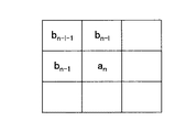
図13は、ベイヤ配列された隣接画素を示した図である。隣接する色成分との相関を利用しanの画素の下位ビットcnを決めるために、隣接しておりかつ、すでに下位ビットが補完された左隣接画素bn-1、右上隣接画素bn-l-1、上隣接画素bn-lの画素データの相関に基づき下位ビットcnを算出し決定する。 FIG. 13 is a diagram illustrating adjacent pixels arranged in a Bayer array. In order to determine the lower bit c n of the pixels using the correlation with adjacent color components a n, and are adjacent, left neighboring pixel b n-1 already lower bits complemented, upper right adjacent pixels b nl −1 , the lower bit c n is calculated and determined based on the correlation of the pixel data of the upper adjacent pixel b nl .
図14を用いて、隣接する色成分との相関から下位ビットcnを算出する方法を説明する。
S141は、圧縮時に切捨てられた10ビット幅の切捨てされた画素データを伸張したものを左に2ビットシフトした図である。S141でビットシフトすることで2ビットMSB側に移動する。次に、S142で下位2ビットであるb0、b1をともに0とする。ここではb0、b1をともに0としている。
With reference to FIG. 14, illustrating a method for calculating the lower-order bits c n from the correlation between the adjacent color components.
S141 is a diagram obtained by shifting the 10-bit-long truncated pixel data that has been truncated at the time of compression to the left by 2 bits. The bit shift is performed in S141 to move to the 2-bit MSB side. Next, in S142, both lower 0 bits b0 and b1 are set to 0. Here, both b0 and b1 are 0.
S143では、S143の式1によりbnを算出する。まず、隣接する画素データであるbn-1とbn-lとbn-l-1を用いてbn=(bn-1+bn-l-bn-l-1)算出する。そして、S143の式2〜式5を参照してbnの結果より条件を満たす値を判断しcnを決定する。
In S143, b n is calculated according to
S143の式2は、bnと予め設定された閾値4(k4)と比較し、bn>k4であればcnを3(〔b0〕〔b1〕→〔1〕〔1〕)にする。
S143の式3は、bnと予め設定された閾値4(k4)、閾値5(k5)と比較し、k5<bn<k4であればcnを2(〔b0〕〔b1〕→〔1〕〔0〕)にする。
S143の式4は、bnと予め設定された閾値5(k5)、閾値6(k6)と比較し、k6<bn<k5であればcnを1(〔b0〕〔b1〕→〔0〕〔1〕)にする。
S143の式5は、bnと予め設定された閾値6(k6)と比較し、bn<k6であればcnを0(〔b0〕〔b1〕→〔0〕〔0〕)にする。
次に、S143で決定した重畳データである補正下位ビットcnを、S144で画素データの下位ビットにcnを重畳する。
ここで、予め設定された閾値k4、k5、k6は、bnの最大値から最小値の範囲で設定される。利用者が好みの画像になるように設定してもかまわない。
Next, the correction lower-order bits c n is a superimposed data determined in S143, superimposing a c n lower bits of the pixel data in S144.
Here, the preset threshold values k 4 , k 5 , k 6 are set in the range from the maximum value of b n to the minimum value. It is possible to set the image so that the user likes it.
図15は図14のS141〜S154を実行させるブロックを示した図である。伸張部151によって圧縮の際に切捨てされた10ビットの画素データを伸張する。次にビットシフト部152でS141とS142の処理を行い、データ保持用メモリ153にはS142の結果を保持し、係数(bn)算出部154では隣接画素データ用メモリ155に記憶されているbn-1とbn-lとbn-l-1を呼び出し、S143の式1に従いbnを算出する。そして重畳データ算出部156でS143の式2〜5の条件によってcnを決定する。算出後、S144に示した動作により重畳データとデータ保持用メモリに記憶した10ビットの左シフト画素データanを加算し12ビットの画素データを生成する。
FIG. 15 is a diagram showing blocks for executing S141 to S154 in FIG. The decompressing
次に、図16を用いてフローの説明をする。
ステップS161では、画素データを圧縮するときに、下位ビットの切捨てを行ったかを判断する。このとき、切捨てを行ったかを判断するための情報は、圧縮時に切捨てビット数などの圧縮情報の一部として記憶してありこの情報を参照して判断を行う。尚、切捨てを行っていた場合はS162に進み、切捨てをしていない場合にはS163に進む。圧縮時の切捨て下位ビット数をどうするかは、ユーザが選択してもいいし、画像条件に基づき自動選択されてもかまわない。
Next, the flow will be described with reference to FIG.
In step S161, it is determined whether or not lower bits have been truncated when the pixel data is compressed. At this time, information for determining whether or not truncation has been performed is stored as a part of the compression information such as the number of bits to be discarded during compression, and the determination is performed with reference to this information. If truncation has been performed, the process proceeds to S162. If truncation has not been performed, the process proceeds to S163. The user can select how the lower-order bits to be cut off at the time of compression are selected, or may be automatically selected based on image conditions.
ステップS162では、圧縮時に決めた切捨てビット数を読込み、ステップS163では、圧縮のときに切捨てをしなかったので切捨てビット数を0にしている。
ステップS164は、圧縮データを伸張し、切捨てされたデータに変換する。
In step S162, the truncation bit number determined at the time of compression is read. In step S163, the truncation bit number is set to 0 because truncation was not performed at the time of compression.
In step S164, the compressed data is decompressed and converted into truncated data.
ステップS165では、切捨てされたデータを読込み、ステップS166で上記切捨てビットが0であるかないかを判断し、YESであれば、下位ビットの重畳処理をしないでS1612に進む。NOであれば、ステップS167に進み、切捨てビット分左にビットシフトする。 In step S165, the truncated data is read. In step S166, it is determined whether or not the truncated bit is 0. If YES, the process proceeds to S1612 without performing the superimposition processing of the lower bits. If NO, the process proceeds to step S167 to shift the bit to the left by the cut bit.
次に、ステップS168で、S143の式1を計算し隣接画素データbn-1とbn-lとbn-l-1より係数bn=(bn-1+bn-l-bn-l-1)で算出する。
次に、ステップS169で上記S143の式2〜5の条件に従い、ステップS1610でcnの値(0、1、2、3)を選び、そして、ステップS1611で上位ビットanと下位ビットcnを加算することで重畳する。
Next, in step S168,
Then, in accordance with the conditions of formula 2-5 above S143 in step S169, to select the values of c n (0, 1, 2, 3) in step S1610, and the upper bits a n and a lower bit c n in step S1611 Are superimposed.
ステップS1612では必要な全ての画素データの処理が終了したかを判断し、全ての処理が終了していればYESに進み終了する。終わっていなければNOに進みS165から再度処理を行う。 In step S1612, it is determined whether processing of all necessary pixel data has been completed. If all processing has been completed, the process proceeds to YES and ends. If not completed, the process proceeds to NO, and the process is performed again from S165.
本実施例では、画素データのビット幅を12ビットとし、上位ビット10ビット、下位ビット2ビットの構成としたが、この構成に限定されるものではない。
尚、対象とする画素データの近傍の画素データとの相関を利用して下位ビットを生成できる。対象とする画素データの両隣の画素データとの相関を利用して下位ビットを生成できる。対象とする画素データの両端以外(上下の隣接または、隣接する画素にさらに隣接する画素)の画素データも含めた相関を利用して下位ビットを生成できる。これら求めた下位ビットと加算することで、画像のエッジや階調の不連続性を除去し、S/Nを改善することが可能になる。
In this embodiment, the bit width of the pixel data is 12 bits, the upper bit is 10 bits, and the lower bit is 2 bits. However, the present invention is not limited to this configuration.
Note that lower bits can be generated by utilizing the correlation with pixel data in the vicinity of the target pixel data. The lower bits can be generated by utilizing the correlation between the pixel data on both sides of the target pixel data. Lower bits can be generated using correlation including pixel data other than both ends of the target pixel data (upper and lower adjacent pixels or pixels further adjacent to adjacent pixels). By adding these low-order bits, it is possible to remove image edge and gradation discontinuity and improve S / N.
尚、画像のエッジや階調の不連続性を除去し、S/Nを改善し良好な階調特性が得られるようにする画像処理ができる範囲であれば変形することが可能である。
(実施例4)
デジタルカメラ等の電子撮像装置の画像は、G(緑)信号の輝度成分に大きく左右されやすい。また、デジタルカメラでは、G(緑)を市松状に配置した原色ベイヤ配列が一般的であり、R(赤)およびB(青)位置のG(緑)信号の予測精度が、解像度・画質向上につながる。
It should be noted that the image processing can be modified as long as the image processing can be performed so as to remove the image edge and gradation discontinuity, improve the S / N, and obtain good gradation characteristics.
Example 4
An image of an electronic imaging device such as a digital camera is easily influenced by the luminance component of the G (green) signal. Digital cameras generally have a primary color Bayer arrangement in which G (green) is arranged in a checkered pattern, and the prediction accuracy of G (green) signals at R (red) and B (blue) positions improves resolution and image quality. Leads to.
画像信号を隣接画素ブロックに分割する場合、各ブロック情報は1本のベクトルで表示できる。各ブロックにおけるR、G、B信号成分のベクトル情報は、特に低彩度領域では高い相関があることが知られている。従来からG補正に利用されているR、B位置の周囲のG信号からの予測値と、RまたはB信号のベクトル情報により、正確なG信号予測を行う方法が知られている。 When an image signal is divided into adjacent pixel blocks, each block information can be displayed as a single vector. It is known that vector information of R, G, and B signal components in each block has a high correlation particularly in a low saturation region. Conventionally, a method for performing accurate G signal prediction based on predicted values from G signals around R and B positions used for G correction and vector information of R or B signals is known.
実施例4では、隣接する色成分との相関とを利用する方法として、上位ビットan(10ビット)と下位ビットcn(2ビット)より構成される12ビットの画素データの処理について説明する。 In the fourth embodiment, processing of 12-bit pixel data composed of upper bits a n (10 bits) and lower bits c n (2 bits) will be described as a method of using correlation with adjacent color components. .
隣接する色成分との相関を利用し画素データの下位ビットを決めるために、G(緑)に隣接する隣接画素R(赤)、隣接画素B(青)の画素データとの色成分同士の色成分相関を算出し下位ビットを決定する。 In order to determine the lower bits of the pixel data using the correlation with the adjacent color components, the colors of the color components of the adjacent pixel R (red) and adjacent pixel B (blue) pixel data adjacent to G (green) The component correlation is calculated to determine the lower bits.
ここでは、処理を簡単にするために、次のような方法について説明する。図17は原色ベイヤ配列を示した図で、R(赤)の横にあるG(緑)をGrとし、B(青)の横にあるG(緑)をGbとして示している。 Here, in order to simplify the processing, the following method will be described. FIG. 17 is a diagram showing a primary color Bayer arrangement, in which G (green) beside R (red) is Gr and G (green) beside B (blue) is Gb.
図18を用いて、隣接する色成分との相関から下位ビットを算出する方法を説明する。
R(赤)の下位ビットを決定する場合は隣接するGrとの相関より求め、Grの下位ビットを求める場合は隣接するR(赤)との相関により決定する。また、B(青)の下位ビットを決定する場合は隣接するGbとの相関より求め、Gbの下位ビットを求める場合は隣接するB(青)との相関により決定する。
A method of calculating lower bits from the correlation with adjacent color components will be described with reference to FIG.
When the lower bit of R (red) is determined, it is obtained from the correlation with the adjacent Gr, and when the lower bit of Gr is obtained, it is determined by the correlation with the adjacent R (red). Further, when the lower bit of B (blue) is determined, it is obtained from the correlation with the adjacent Gb, and when the lower bit of Gb is obtained, it is determined by the correlation with the adjacent B (blue).
例えば、R(赤)画素の下位ビットを隣接するGr画素との相関から算出する場合を考える。
S181は、R(赤)の圧縮時に切捨てられた10ビット幅の画素データを伸張したものを左に2ビットシフトした図である。S181でビットシフトすることで2ビットがMSB側に移動するため、S182で下位2ビットであるb0、b1をともに0にする。
For example, consider a case where the lower bits of the R (red) pixel are calculated from the correlation with the adjacent Gr pixel.
S181 is a diagram in which 10-bit wide pixel data that has been discarded during R (red) compression is expanded by 2 bits to the left. Since the two bits are moved to the MSB side by bit shifting in S181, both lower bits b0 and b1 are set to 0 in S182.
S183では、S183の式1によりωnと下位ビットcnを算出する。まず、隣接する画素データのR(赤)とGrの上位ビット(10ビットの画素データ)用いてωn( )=A(Gr)を算出する。ここでAは、デジタルカメラの写した画像全体から特性を算出しR(赤)、G(緑)、B(青)の相関を求めた関数である。相関を算出する関数は、テーブルを用意してもいいし、一次関数、n次関数、n次多項式、回帰分析等を算出して使用してもかまわない。尚、Aは原色ベイヤ配列されたGrと隣接するR(赤)またはGbと隣接するB(青)の相関に基づく関数であってもよい。
In S183, ω n and the lower bit c n are calculated by
そして、cnは、関数ωn( )に対象画素に隣接する画素データを代入することで決まり、この場合も、テーブルなどを用意してcnを求める。例えば、下位2ビットを決めるのであれば実施例2のように閾値を決めて0〜3を選択してもかまわない。 Then, c n is determined by substituting the pixel data adjacent to the target pixel in function omega n (), also in this case, obtaining the c n are prepared as tables. For example, if the lower 2 bits are determined, the threshold value may be determined as in the second embodiment and 0 to 3 may be selected.
そして、対象の隣接画素の上位ビットan-1をωnによって演算して下位ビットcnを算出する。そして、S183の式1の結果よりcnを決定する。
次に、S183で決定した重畳データである補正下位ビットcnを、S184で上位ビットanに重畳する。
Then, the upper bit a n−1 of the target adjacent pixel is calculated by ω n to calculate the lower bit c n . Then, to determine c n from the results of
Next, the correction lower-order bits c n is a superimposed data determined in S183, superimposed on the higher-order bits a n in S184.
図19は図18のS181〜S184を実行させるブロックを示した図である。伸張部191によって切捨てされた10ビットの画素データを伸張する。次にビットシフト部192でS181とS182の処理を行い、データ保持用メモリ193にはS182の結果を保持し、重畳係数読込部194では重畳係数用メモリ195に記憶されている全画素データの中からan-1とan+1を呼び出し、S183に従いcnを算出する。そして重畳データ算出部196でcnを決定する。算出後、S184に示した動作により重畳データとデータ保持用メモリに記憶した10ビットの左シフト画素データanを加算し12ビットの画素データを生成する。
FIG. 19 is a diagram showing blocks for executing S181 to S184 of FIG. The 10-bit pixel data truncated by the
次に、図20を用いてフローの説明をする。
ステップS201では、画素データを圧縮するときに、下位ビットの切捨てを行ったかを判断する。このとき、切捨てを行ったかを判断するための情報は、圧縮時に切捨てビット数などの圧縮情報の一部として記憶してありこの情報を参照して判断を行う。尚、切捨てを行っていた場合はS202に進み、切捨てをしていない場合にはS203に進む。圧縮時の切捨てをするかどうかは、ユーザが選択してもいいし、画像条件に基づき自動選択されてもかまわない。
Next, the flow will be described with reference to FIG.
In step S201, it is determined whether the lower bits have been truncated when the pixel data is compressed. At this time, information for determining whether or not truncation has been performed is stored as a part of the compression information such as the number of bits to be discarded during compression, and the determination is performed with reference to this information. If truncation has been performed, the process proceeds to S202, and if truncation has not been performed, the process proceeds to S203. Whether or not to cut off during compression may be selected by the user, or may be automatically selected based on image conditions.
ステップS202では、圧縮時に決めた切捨てビット数を読込み、ステップS203では、切捨てをしなかったので切捨てビット数を0にしている。
ステップS204は、圧縮データを伸張し、切捨てされたデータに変換する。
In step S202, the number of truncation bits determined at the time of compression is read. In step S203, the truncation bit number is set to 0 because no truncation is performed.
In step S204, the compressed data is decompressed and converted into truncated data.
ステップS205では、切捨てされたデータを読込み、ステップS206で上記切捨てビットが0であるかないかを判断し、YESであれば、下位ビットの重畳処理をしないでS2011に進む。NOであれば、ステップS207に進み、切捨てビット分左にビットシフトする。 In step S205, the truncated data is read, and in step S206, it is determined whether or not the truncated bit is 0. If YES, the process proceeds to S2011 without performing the superimposition processing of the lower bits. If NO, the process proceeds to step S207 to shift the bit to the left by the cut bit.
次に、ステップS208で、重畳係数を読込み、ステップS209で、S203の演算により下位ビットcnを算出する。そして、ステップS2010で、上位ビットanと下位ビットcnを加算することで重畳する。 Next, in step S208, reads the superposition coefficients, at step S209, calculates the lower-order bits c n by the operation of S203. Then, in step S2010, superimposed by adding the higher-order bits a n and a lower bit c n.
ステップS2011では必要な全ての画素データの処理が終了したかを判断し、全ての処理が終了していればYESに進み終了する。終わっていなければNOに進みS205から再度処理を行う。 In step S2011, it is determined whether processing of all necessary pixel data has been completed. If all processing has been completed, the process proceeds to YES and ends. If not completed, the process proceeds to NO, and the process is performed again from S205.
本実施例では、画素データのビット幅を12ビットとし、上位ビット10ビット、下位ビット2ビットの構成としたが、この構成に限定されるものではない。上記構成によれば、原色ベイヤ配列された画像データにおいて、対象とする画素データの異色成分の画素データとの相関を利用して、下位ビットを生成できる。 In this embodiment, the bit width of the pixel data is 12 bits, the upper bit is 10 bits, and the lower bit is 2 bits. However, the present invention is not limited to this configuration. According to the above configuration, in the image data arranged in the primary color Bayer array, the lower bits can be generated by utilizing the correlation with the pixel data of the different color component of the target pixel data.
画像データ全体から色成分相関を算出し、その色成分相関を利用して下位ビットを生成できる。また、画像データを分割して分割したブロック内画像データの色成分相関を算出し、その相関を利用して、下位ビットを生成できる。また、色成分相関により算出した値からテーブルを検索し、切捨てした下位ビットの幅の下位ビットを探し、それらの下位ビットを加算することで、画像のエッジや階調の不連続性を除去し、S/Nを改善することが可能になる。
(変形例)
階調数の少ないデータに対し、データを重畳することにより階調数を増やすことが出来る。この効果として、画像処理によって生ずる不自然な階調変化を除去することができる。
The color component correlation is calculated from the entire image data, and the lower bit can be generated using the color component correlation. Further, the color component correlation of the divided intra-block image data is calculated by dividing the image data, and the lower bits can be generated using the correlation. In addition, the table is searched from the value calculated by the color component correlation, the lower bits of the lower bit width are discarded, and the lower bits are added to remove the image edge and gradation discontinuity. S / N can be improved.
(Modification)
The number of gradations can be increased by superimposing data on data with a small number of gradations. As this effect, an unnatural gradation change caused by image processing can be removed.
例えば、エッジや階調部に対して、トーンジャンプを緩和することが出来る。
実施例においてはデジタルカメラを用いて説明したが、特許請求の範囲に記載された本発明の要旨を逸脱しない限りその他の画像処理装置にも適用可能である。
For example, tone jump can be relaxed with respect to edges and gradation portions.
Although the embodiments have been described using a digital camera, the present invention can be applied to other image processing apparatuses as long as they do not depart from the gist of the present invention described in the claims.
1 ・・・ CPU−A
2 ・・・ EEPROM
3 ・・・ レンズ
4 ・・・ CCD
5 ・・・ 撮像回路
6 ・・・ A/D変換部
7 ・・・ 補正回路
8 ・・・ フレームメモリ
9 ・・・ CPU−B
10 ・・・ FIFOメモリ
11 ・・・ 記録媒体I/F
12 ・・・ バス
13 ・・・ 記録媒体
14 ・・・ ビデオエンコード回路
15 ・・・ ビデオ出力回路
16 ・・・ ビデオ出力端子
17 ・・・ TFT液晶駆動回路
18 ・・・ TFTパネル
19 ・・・ バックライトユニット
20 ・・・ アクチュエータ
21 ・・・ アクチュエータ駆動回路
22 ・・・ 外部データI/F
23 ・・・ キーマトリクス部
24 ・・・ LCD表示回路
25 ・・・ LCDパネル
26 ・・・ 電池
27 ・・・ 電源回路
1 ... CPU-A
2 ... EEPROM
3 ...
DESCRIPTION OF
10: FIFO memory 11: Recording medium I / F
DESCRIPTION OF SYMBOLS 12 ...
23 ...
Claims (12)
前記画像データを構成する1以上の前記参照画素データに基づいて前記注目画素データの下位ビットを算出して補正下位ビットとする下位ビット算出手段と、
前記下位ビット算出手段より求めた前記補正下位ビットと前記注目画素データとを加算する手段と、
を具備することを特徴とする画像処理装置。 In an image processing apparatus that predicts lower bits of pixel-of-interest data based on one or more reference pixel data constituting image data,
Low-order bit calculation means for calculating a low-order bit of the pixel-of-interest data based on one or more of the reference pixel data constituting the image data and making it a corrected low-order bit;
Means for adding the corrected lower bit obtained by the lower bit calculating means and the target pixel data;
An image processing apparatus comprising:
前記画像データを構成する1以上の前記参照画素データに基づいて前記注目画素データの下位ビットを算出して補正下位ビットとする下位ビット算出機能と、
前記下位ビット算出機能より求めた前記補正下位ビットと前記注目画素の上位ビットとを加算する加算機能と、
をコンピュータに実現させるためのプログラム。 A program for causing a computer to execute image processing for predicting lower bits of the pixel data based on one or more pieces of pixel data constituting the image data,
A low-order bit calculation function that calculates a low-order bit of the pixel-of-interest data based on one or more reference pixel data constituting the image data and sets it as a corrected low-order bit;
An addition function for adding the corrected lower bit obtained from the lower bit calculation function and the upper bit of the target pixel;
A program to make a computer realize.
12. The computer-implemented program according to claim 11, wherein the corrected lower bits calculate lower bits of the pixel-of-interest data based on upper bits of the reference pixel data.
Priority Applications (2)
| Application Number | Priority Date | Filing Date | Title |
|---|---|---|---|
| JP2004200753A JP2006025123A (en) | 2004-07-07 | 2004-07-07 | Image processor |
| US11/158,255 US7446782B2 (en) | 2004-07-07 | 2005-06-21 | Image processing device |
Applications Claiming Priority (1)
| Application Number | Priority Date | Filing Date | Title |
|---|---|---|---|
| JP2004200753A JP2006025123A (en) | 2004-07-07 | 2004-07-07 | Image processor |
Publications (2)
| Publication Number | Publication Date |
|---|---|
| JP2006025123A true JP2006025123A (en) | 2006-01-26 |
| JP2006025123A5 JP2006025123A5 (en) | 2008-05-15 |
Family
ID=35541430
Family Applications (1)
| Application Number | Title | Priority Date | Filing Date |
|---|---|---|---|
| JP2004200753A Pending JP2006025123A (en) | 2004-07-07 | 2004-07-07 | Image processor |
Country Status (2)
| Country | Link |
|---|---|
| US (1) | US7446782B2 (en) |
| JP (1) | JP2006025123A (en) |
Cited By (2)
| Publication number | Priority date | Publication date | Assignee | Title |
|---|---|---|---|---|
| JP2009239702A (en) * | 2008-03-27 | 2009-10-15 | Mega Chips Corp | Image processor |
| JP2013035142A (en) * | 2011-08-03 | 2013-02-21 | Ricoh Co Ltd | Image data transfer device and inkjet recording apparatus |
Families Citing this family (5)
| Publication number | Priority date | Publication date | Assignee | Title |
|---|---|---|---|---|
| US9076239B2 (en) | 2009-04-30 | 2015-07-07 | Stmicroelectronics S.R.L. | Method and systems for thumbnail generation, and corresponding computer program product |
| KR101410249B1 (en) * | 2013-05-09 | 2014-06-20 | 주식회사 이노와이어리스 | data compression and decompression method between digital unit and radio unit in cloud radio access network |
| GB2567881B (en) | 2017-10-30 | 2021-02-10 | Imagination Tech Ltd | Systems and methods for processing a stream of data values |
| GB2568039B (en) * | 2017-10-30 | 2020-10-28 | Imagination Tech Ltd | Systems and methods for processing a stream of data values |
| JP7466280B2 (en) * | 2019-09-05 | 2024-04-12 | キヤノン株式会社 | Inspection device, control method thereof, and program |
Family Cites Families (12)
| Publication number | Priority date | Publication date | Assignee | Title |
|---|---|---|---|---|
| JP3313399B2 (en) * | 1991-09-20 | 2002-08-12 | 株式会社リコー | Image processing device |
| US6415065B1 (en) * | 1995-08-04 | 2002-07-02 | Canon Kabushiki Kaisha | Image processing apparatus and method therefor |
| US5699079A (en) | 1995-11-21 | 1997-12-16 | Silicon Graphics, Inc. | Restoration filter for truncated pixels |
| JPH1013673A (en) | 1996-06-18 | 1998-01-16 | Fuji Photo Film Co Ltd | Method and device for processing digital image signal |
| JPH10173488A (en) | 1996-12-13 | 1998-06-26 | Hitachi Ltd | Digital signal processing device and display using the same |
| JP2000041152A (en) * | 1998-07-22 | 2000-02-08 | Nec Ic Microcomput Syst Ltd | Color signal converting device and method |
| DE69936368T2 (en) * | 1998-09-22 | 2007-10-31 | Matsushita Electric Industrial Co., Ltd., Kadoma | Improved display method for grayscale images |
| JP4196039B2 (en) | 1998-12-21 | 2008-12-17 | 株式会社ニコン | Image data compression method |
| US6744929B1 (en) * | 1999-11-18 | 2004-06-01 | Nikon Corporation | Image data compression method image data compression apparatus and recording medium and data signal for providing image data compression program |
| US6876468B1 (en) * | 2000-09-19 | 2005-04-05 | Kabushiki Kaisha Toshiba | Image processing apparatus that performs black coloring, gamma correction and tone processing |
| US8009327B2 (en) * | 2002-07-11 | 2011-08-30 | Canon Kabushiki Kaisha | Method and apparatus for image processing |
| JP2004159384A (en) * | 2002-11-01 | 2004-06-03 | Sanyo Denki Co Ltd | Method for jointing rubber magnet to yoke |
-
2004
- 2004-07-07 JP JP2004200753A patent/JP2006025123A/en active Pending
-
2005
- 2005-06-21 US US11/158,255 patent/US7446782B2/en not_active Expired - Fee Related
Cited By (2)
| Publication number | Priority date | Publication date | Assignee | Title |
|---|---|---|---|---|
| JP2009239702A (en) * | 2008-03-27 | 2009-10-15 | Mega Chips Corp | Image processor |
| JP2013035142A (en) * | 2011-08-03 | 2013-02-21 | Ricoh Co Ltd | Image data transfer device and inkjet recording apparatus |
Also Published As
| Publication number | Publication date |
|---|---|
| US7446782B2 (en) | 2008-11-04 |
| US20060008155A1 (en) | 2006-01-12 |
Similar Documents
| Publication | Publication Date | Title |
|---|---|---|
| US7176962B2 (en) | Digital camera and digital processing system for correcting motion blur using spatial frequency | |
| US6812969B2 (en) | Digital camera | |
| JP4869149B2 (en) | Image data compression apparatus, image data compression method and program | |
| JP2008236726A (en) | Imaging apparatus, imaging system, imaging method, and image processor | |
| JP2004304712A (en) | Image processing method and apparatus | |
| JP4433883B2 (en) | White balance correction device, white balance correction method, program, and electronic camera device | |
| US7446782B2 (en) | Image processing device | |
| US20080285866A1 (en) | Apparatus and method for image data compression | |
| JP5092536B2 (en) | Image processing apparatus and program thereof | |
| JP2006345388A (en) | Imaging apparatus | |
| JP2008312193A (en) | Image data compressing device, image data compressing method, and program | |
| JP2009182599A (en) | Image processor, image processing method, image processing program, and imaging device | |
| JP4638392B2 (en) | Image recording device | |
| JP2006253970A (en) | Imaging apparatus, shading correction data generating method, and program | |
| JP2008294945A (en) | Imaging device, automatic control method therefor and automatic control program therefor | |
| JP2008219230A (en) | Imaging apparatus, and image processing method | |
| JP2006203557A (en) | Imaging apparatus and its control method | |
| JP2008067298A (en) | Photography apparatus and program | |
| JP2004005424A (en) | Signal processor for reducing noise of image signal, signal processing program and signal processing method | |
| JP3988371B2 (en) | Image data compression method, computer-readable recording medium on which image data compression program is recorded, and digital still camera | |
| JP2004147247A (en) | Imaging apparatus | |
| JP2005275454A (en) | Image processing method, image processing system, image processing device and image processing program | |
| JP2010041534A (en) | Image processing method, image processing program and imaging apparatus | |
| JP2018046467A (en) | Imaging apparatus and control method thereof | |
| JP2005191711A (en) | Imaging system and method therefor, regeneration system and program thereof, and imaging regeneration system and program thereof |
Legal Events
| Date | Code | Title | Description |
|---|---|---|---|
| A621 | Written request for application examination |
Free format text: JAPANESE INTERMEDIATE CODE: A621 Effective date: 20070306 |
|
| A521 | Written amendment |
Free format text: JAPANESE INTERMEDIATE CODE: A523 Effective date: 20080327 |
|
| A977 | Report on retrieval |
Free format text: JAPANESE INTERMEDIATE CODE: A971007 Effective date: 20080604 |
|
| A131 | Notification of reasons for refusal |
Free format text: JAPANESE INTERMEDIATE CODE: A131 Effective date: 20080624 |
|
| A02 | Decision of refusal |
Free format text: JAPANESE INTERMEDIATE CODE: A02 Effective date: 20081021 |