JP2006019302A - Hydrogen storage-based rechargeable fuel cell system and method - Google Patents
Hydrogen storage-based rechargeable fuel cell system and method Download PDFInfo
- Publication number
- JP2006019302A JP2006019302A JP2005193608A JP2005193608A JP2006019302A JP 2006019302 A JP2006019302 A JP 2006019302A JP 2005193608 A JP2005193608 A JP 2005193608A JP 2005193608 A JP2005193608 A JP 2005193608A JP 2006019302 A JP2006019302 A JP 2006019302A
- Authority
- JP
- Japan
- Prior art keywords
- hydrogen
- electrode
- electrochemical system
- mode
- membrane
- Prior art date
- Legal status (The legal status is an assumption and is not a legal conclusion. Google has not performed a legal analysis and makes no representation as to the accuracy of the status listed.)
- Pending
Links
Images


Classifications
-
- H—ELECTRICITY
- H01—ELECTRIC ELEMENTS
- H01M—PROCESSES OR MEANS, e.g. BATTERIES, FOR THE DIRECT CONVERSION OF CHEMICAL ENERGY INTO ELECTRICAL ENERGY
- H01M4/00—Electrodes
- H01M4/86—Inert electrodes with catalytic activity, e.g. for fuel cells
- H01M4/90—Selection of catalytic material
- H01M4/9016—Oxides, hydroxides or oxygenated metallic salts
-
- B—PERFORMING OPERATIONS; TRANSPORTING
- B82—NANOTECHNOLOGY
- B82Y—SPECIFIC USES OR APPLICATIONS OF NANOSTRUCTURES; MEASUREMENT OR ANALYSIS OF NANOSTRUCTURES; MANUFACTURE OR TREATMENT OF NANOSTRUCTURES
- B82Y30/00—Nanotechnology for materials or surface science, e.g. nanocomposites
-
- H—ELECTRICITY
- H01—ELECTRIC ELEMENTS
- H01M—PROCESSES OR MEANS, e.g. BATTERIES, FOR THE DIRECT CONVERSION OF CHEMICAL ENERGY INTO ELECTRICAL ENERGY
- H01M4/00—Electrodes
- H01M4/86—Inert electrodes with catalytic activity, e.g. for fuel cells
- H01M4/90—Selection of catalytic material
- H01M4/92—Metals of platinum group
-
- H—ELECTRICITY
- H01—ELECTRIC ELEMENTS
- H01M—PROCESSES OR MEANS, e.g. BATTERIES, FOR THE DIRECT CONVERSION OF CHEMICAL ENERGY INTO ELECTRICAL ENERGY
- H01M8/00—Fuel cells; Manufacture thereof
- H01M8/08—Fuel cells with aqueous electrolytes
- H01M8/083—Alkaline fuel cells
-
- H—ELECTRICITY
- H01—ELECTRIC ELEMENTS
- H01M—PROCESSES OR MEANS, e.g. BATTERIES, FOR THE DIRECT CONVERSION OF CHEMICAL ENERGY INTO ELECTRICAL ENERGY
- H01M8/00—Fuel cells; Manufacture thereof
- H01M8/18—Regenerative fuel cells, e.g. redox flow batteries or secondary fuel cells
- H01M8/184—Regeneration by electrochemical means
- H01M8/186—Regeneration by electrochemical means by electrolytic decomposition of the electrolytic solution or the formed water product
-
- H—ELECTRICITY
- H01—ELECTRIC ELEMENTS
- H01M—PROCESSES OR MEANS, e.g. BATTERIES, FOR THE DIRECT CONVERSION OF CHEMICAL ENERGY INTO ELECTRICAL ENERGY
- H01M4/00—Electrodes
- H01M4/02—Electrodes composed of, or comprising, active material
- H01M4/36—Selection of substances as active materials, active masses, active liquids
- H01M4/38—Selection of substances as active materials, active masses, active liquids of elements or alloys
- H01M4/383—Hydrogen absorbing alloys
-
- Y—GENERAL TAGGING OF NEW TECHNOLOGICAL DEVELOPMENTS; GENERAL TAGGING OF CROSS-SECTIONAL TECHNOLOGIES SPANNING OVER SEVERAL SECTIONS OF THE IPC; TECHNICAL SUBJECTS COVERED BY FORMER USPC CROSS-REFERENCE ART COLLECTIONS [XRACs] AND DIGESTS
- Y02—TECHNOLOGIES OR APPLICATIONS FOR MITIGATION OR ADAPTATION AGAINST CLIMATE CHANGE
- Y02E—REDUCTION OF GREENHOUSE GAS [GHG] EMISSIONS, RELATED TO ENERGY GENERATION, TRANSMISSION OR DISTRIBUTION
- Y02E60/00—Enabling technologies; Technologies with a potential or indirect contribution to GHG emissions mitigation
- Y02E60/10—Energy storage using batteries
-
- Y—GENERAL TAGGING OF NEW TECHNOLOGICAL DEVELOPMENTS; GENERAL TAGGING OF CROSS-SECTIONAL TECHNOLOGIES SPANNING OVER SEVERAL SECTIONS OF THE IPC; TECHNICAL SUBJECTS COVERED BY FORMER USPC CROSS-REFERENCE ART COLLECTIONS [XRACs] AND DIGESTS
- Y02—TECHNOLOGIES OR APPLICATIONS FOR MITIGATION OR ADAPTATION AGAINST CLIMATE CHANGE
- Y02E—REDUCTION OF GREENHOUSE GAS [GHG] EMISSIONS, RELATED TO ENERGY GENERATION, TRANSMISSION OR DISTRIBUTION
- Y02E60/00—Enabling technologies; Technologies with a potential or indirect contribution to GHG emissions mitigation
- Y02E60/30—Hydrogen technology
- Y02E60/50—Fuel cells
Abstract
Description
本発明は、一般に電気化学システムの分野に関する。より詳細には、本発明は、水素化物及び電気エネルギの形態で水素を発生させることができるデュアルモードの電気化学システムに関する。 The present invention relates generally to the field of electrochemical systems. More particularly, the present invention relates to a dual mode electrochemical system capable of generating hydrogen in the form of hydride and electrical energy.
燃料電池技術は、有害物質の排出を有意に減少させる可能性を有する。燃料電池は、効率的なエネルギ変換が可能であり、輸送機関用途、携帯用電源、家庭用及び業務用発電、大出力発電及びこのようなシステムを使用することにより恩恵を受けるあらゆる他の用途を含む様々な用途で使用することができる。輸送機関用途に関しては、燃料電池は、ガソリン又はディーゼルなどの化石燃料を燃焼させる従来の内燃エンジンを備えた自動車に対して有望な代替案を提示する。内燃エンジンは、有害なパティキュレートを発生し、大気に対する温室効果ガスを付加する。他方、燃料電池車は、純水素で燃料が供給され、単に水と、電力及び熱の形態でエネルギを放出する。実際、燃料電池車は、従来の車両に比べて2倍の効率となる可能性がある。 Fuel cell technology has the potential to significantly reduce emissions of hazardous substances. Fuel cells are capable of efficient energy conversion and are used in transportation applications, portable power sources, household and commercial power generation, high power generation and any other application that would benefit from using such a system. It can be used in various applications including. For transportation applications, fuel cells present a promising alternative to vehicles with conventional internal combustion engines that burn fossil fuels such as gasoline or diesel. Internal combustion engines generate harmful particulates and add greenhouse gases to the atmosphere. On the other hand, fuel cell vehicles are supplied with fuel in pure hydrogen and simply release energy in the form of water, power and heat. In fact, fuel cell vehicles can be twice as efficient as conventional vehicles.
通常、燃料電池は、水素燃料と酸素とを水に変換して、プロセス中で電気と熱と発生する化学プロセスによりエネルギを生成する。燃料電池は、反応物質が絶えず新しくなるバッテリーによく似た動作をする。バッテリーは、電気により再充電されるが、燃料電池は、水素と酸素とを使用して再充電される。燃料電池スタックは、燃料発生源によって供給された水素を使用して電気を発生し、車両を動かす1つ又はそれ以上の電動機を含む任意の装置に電力を供給する。燃料電池スタックは、数百の個別の燃料電池からなるものとすることができる。多くの場合、バッテリーは、燃料電池スタックによって、及び回生制動システムなどの車両の他のシステムによって発生した電気を貯蔵するのに使用される。また、バッテリー内に貯蔵されたエネルギを用いて、車両の電動機並びに追加の電気システに動力を供給することができる。 Typically, a fuel cell converts hydrogen fuel and oxygen into water and generates energy through a chemical process that generates electricity and heat during the process. A fuel cell operates much like a battery with constantly changing reactants. The battery is recharged by electricity, while the fuel cell is recharged using hydrogen and oxygen. The fuel cell stack uses the hydrogen supplied by the fuel generation source to generate electricity and provide power to any device including one or more electric motors that move the vehicle. A fuel cell stack may consist of hundreds of individual fuel cells. In many cases, batteries are used to store electricity generated by the fuel cell stack and by other systems in the vehicle, such as regenerative braking systems. Also, the energy stored in the battery can be used to power the vehicle motor as well as the additional electrical system.
保有する貯蔵エネルギに限定されるバッテリーとは異なり、燃料電池は、燃料が供給されている限りエネルギを発生させることができる。バッテリー式の電気自動車は、バッテリー内に貯蔵された外部発生源からの電気を使用するが、燃料電池は、自己の電気を生成する。燃料電池はまた、電気自動車用の従来のバッテリーよりも大きなエネルギ密度又は電流密度を供給することができ、より大量のエネルギを連続して生成することが可能となる。これにより、燃料電池自動車が現行のガソリン駆動の車両で見られるものよりも更に高度で強力な電気システムを装備できるようになる。例えば、車両の制御センサの数が増えると、操縦システム及び制動システムを改善することができ、自動車がより安全になる。 Unlike batteries, which are limited to the stored energy they hold, fuel cells can generate energy as long as fuel is supplied. Battery powered electric vehicles use electricity from an external source stored in the battery, while fuel cells generate their own electricity. The fuel cell can also supply a greater energy density or current density than conventional batteries for electric vehicles, allowing a greater amount of energy to be produced continuously. This allows fuel cell vehicles to be equipped with more sophisticated and powerful electrical systems than those found in current gasoline powered vehicles. For example, as the number of vehicle control sensors increases, the steering and braking systems can be improved and the vehicle becomes safer.
燃料としてセル内で使用される水素は、天然ガス、メタノールなどなどの化石燃料から改質プロセスを介して生成することができる。この改質プロセスによって発生した水素は、純粋でなく、燃料電池の効率を低下させる。炭化水素燃料を水素に変換するために改質装置を付加すると、燃料電池の全効率が約30から40パーセントに低下する。
従って、連続運転を可能とするために燃料電池内に水素を常に発生させて貯蔵する効果的で効率的な方法を見出すことに対して当該技術分野での必要性が存在する。また更に、必要とされていることは、内部発生源からエネルギを引き出してこれをシステム内に貯蔵する再充電可能な燃料電池システムである。 Accordingly, there is a need in the art for finding an effective and efficient way to constantly generate and store hydrogen in a fuel cell to enable continuous operation. Still further, what is needed is a rechargeable fuel cell system that draws energy from internal sources and stores it in the system.
1つの態様において、デュアルモード電気化学システムは、水素を貯蔵可能な第1の電極と、第2の電極と、これらの間に介在された実質的に電気絶縁し且つ実質的にイオン伝導性の膜と、電解質とを含む。第1のモードにおいて、水と電気とが導入されると、デュアルモード電気化学システムは、電解質の存在下で水を電解し、膜の両側で水素と酸素とを発生させる。水素は、第1の電極内に貯蔵される。第2のモードにおいて、第2の電極に酸化性物質が導入されると、デュアルモード電気化学システムは、貯蔵された水素と酸化性物質とが膜の両側で反応することによって水と電気とを発生させる。 In one aspect, a dual mode electrochemical system includes a first electrode capable of storing hydrogen, a second electrode, and a substantially electrically insulating and substantially ionically conductive material interposed therebetween. Including a membrane and an electrolyte. In the first mode, when water and electricity are introduced, the dual mode electrochemical system electrolyzes water in the presence of electrolyte and generates hydrogen and oxygen on both sides of the membrane. Hydrogen is stored in the first electrode. In the second mode, when an oxidant is introduced into the second electrode, the dual mode electrochemical system causes water and electricity to react with the stored hydrogen and oxidant on both sides of the membrane. generate.
更に別の態様において、デュアルモード電気化学システムは水素を貯蔵可能なアノードを含む。アノードは、導電性ポリマー、セラミック、金属、金属水素化物、有機水素化物、二元複合材料、二元−三元複合材料、ナノ複合材料料及びカーボン・ナノ構造体の少なくとも1つを含む。デュアルモード電気化学システムは更に、カソードと、アノードとカソードとの間に介在された実質的に電気絶縁し且つ実質的にイオン伝導性の膜と、電解質と、を含む。充電モードにおいては、水と電気とが導入されると、デュアルモード電気化学システムは、電解質存在下で水を電解し、膜の両側で水素と酸素とを発生させ、水素はアノード内に貯蔵される。放電モードにおいては、カソードに酸化性物質が導入されると、デュアルモード電気化学システムは、貯蔵された水素と酸化性物質とが膜の両側で反応することによって水と電気とを発生させる。 In yet another embodiment, the dual mode electrochemical system includes an anode capable of storing hydrogen. The anode includes at least one of a conductive polymer, a ceramic, a metal, a metal hydride, an organic hydride, a binary composite, a binary-ternary composite, a nanocomposite material, and a carbon nanostructure. The dual mode electrochemical system further includes a cathode, a substantially electrically insulating and substantially ion conducting membrane interposed between the anode and the cathode, and an electrolyte. In charge mode, when water and electricity are introduced, the dual mode electrochemical system electrolyzes water in the presence of electrolyte, generating hydrogen and oxygen on both sides of the membrane, and the hydrogen is stored in the anode. The In the discharge mode, when an oxidant is introduced into the cathode, the dual mode electrochemical system generates water and electricity by reacting the stored hydrogen and oxidant on both sides of the membrane.
更に別の態様においては、デュアルモード電気化学システムは、水素を貯蔵可能なアノードと、カソードと、アノードとカソードとの間に介在された実質的に電気絶縁し且つ実質的にイオン伝導性の膜を含む。デュアルモード電気化学システムは更に、膜に隣接して配置された触媒と、電解質とを含む。充電モードにおいては、水と電気とが導入されると、デュアルモード電気化学システムは、電解質存在下で水を電解し、膜の両側で水素と酸素とを発生させ、水素はアノード内に貯蔵される。放電モードにおいては、カソードに酸化性物質が導入されると、デュアルモード電気化学システムは、蓄えられた水素と酸化性物質とが膜の両側で反応することによって水と電気とを発生させる。 In yet another aspect, a dual mode electrochemical system includes an anode capable of storing hydrogen, a cathode, and a substantially electrically insulating and substantially ion conductive membrane interposed between the anode and the cathode. including. The dual mode electrochemical system further includes a catalyst disposed adjacent to the membrane and an electrolyte. In charge mode, when water and electricity are introduced, the dual mode electrochemical system electrolyzes water in the presence of electrolyte, generating hydrogen and oxygen on both sides of the membrane, and the hydrogen is stored in the anode. The In the discharge mode, when an oxidant is introduced into the cathode, the dual mode electrochemical system generates water and electricity as the stored hydrogen and oxidant react on both sides of the membrane.
更に別の態様においては、デュアルモード電気化学システムを充放電する方法は、水と電気とをデュアルモード電気化学システムに導入する段階と、第1の電極と第2の電極との間に介在された電気絶縁し且つ実質的にイオン伝導性の膜の両側で水素と酸素とを発生させる段階とを含む。この方法は更に、第1の電極に水素を貯蔵する段階と、第2の電極に酸化性物質を導入する段階とを含む。水素と酸素とは膜の両側で反応し、これにより水と電気とを発生させる。 In yet another aspect, a method for charging and discharging a dual mode electrochemical system includes introducing water and electricity into the dual mode electrochemical system and interposed between a first electrode and a second electrode. Generating hydrogen and oxygen on both sides of the electrically insulating and substantially ion conductive membrane. The method further includes storing hydrogen at the first electrode and introducing an oxidizing material into the second electrode. Hydrogen and oxygen react on both sides of the membrane, thereby generating water and electricity.
図面全体を通して同じ参照符合が同じ部品を表す添付図面を参照しながら以下の詳細な説明を読めば、本発明のこれら及び他の特徴、態様、及び利点がより良く理解されるであろう。 These and other features, aspects and advantages of the present invention will be better understood when the following detailed description is read with reference to the accompanying drawings in which like reference characters represent like parts throughout the drawings.
必要に応じて、本発明の詳細な実施形態が本明細書で開示される。しかしながら、開示される実施形態は、種々の形態及び代替形態で具現化できる本発明の例証に過ぎない点を理解されたい。本明細書に開示された特定の構造的及び機能的詳細は、限定として解釈すべきではなく、単に本発明を広く用いるために当業者に教示するための代表的な根拠として、特許請求の範囲に関する根拠と解釈すべきである。図面全体を通して同じ部品には同じ符号が付与されている。 As required, detailed embodiments of the present invention are disclosed herein. However, it should be understood that the disclosed embodiments are merely illustrative of the invention that may be embodied in various forms and alternatives. The specific structural and functional details disclosed herein are not to be construed as limitations, but merely as a representative basis for teaching those of ordinary skill in the art for broad use of the present invention. Should be interpreted as the basis for The same parts are given the same reference numerals throughout the drawings.
図1は、水素を貯蔵可能な第1の電極4と、第2の電極6とを含む例示的なデュアルモード電気化学システム2を示す。実質的に電気絶縁されたイオン伝導性の膜8は、第1の電極4と第2の電極6との間に配置されている。電気化学システム2は更に、電解質を含む。デュアルモード運転において、この電気化学システム2は、第1のモードと第2のモードとで運転する。運転中、電気化学システム2の第1のモードの間、電気化学システムに水12及び電気が加えられる。幾つかの実施形態において、電気は、外部回路10を通じて供給を受けることができる。この外部回路は、充電回路11と負荷13とを含む。デュアル電気化学システム2は、電解質の存在下で水18を電解し、膜8の両側に水素と酸素とを発生させる。電解プロセスで発生した水素は、第1の電極4に貯蔵される。デュアル電気化学システム2の第1のモードは、一般に充電モードと呼ばれ、水素が生成されて第1の電極4に貯蔵される。運転の第2のモードにおいて、デュアルモード電気化学システム2は、燃料電池として運転し、酸化剤14が導入されると、貯蔵された水素が膜8の両側で酸化剤14と反応して化学反応を生じ、水と電気とを発生する。従って、第1のモードすなわち充電モードにおいては、デュアルモード電気化学システムは、原理上電気分解装置のように機能し、この場合水は、電解質存在下で電気を印加することによって水素と酸素とに分解される。しかしながら、第2のモードすなわち放電モードにおいては、デュアルモード電気化学システムは燃料電池として機能し、この場合水素と酸素が反応して水と電気とを作る。
FIG. 1 shows an exemplary dual mode
幾つかの実施形態においては、第1の電極4はアノードであり、第2の電極6はカソードである。本明細書に開示された全ての実施形態において、理解し易いように第1の電極4をアノードと呼び、第2の電極6をカソードと呼ぶ。例示的な実施形態においては、図1に示すように、膜8は2つの側部、すなわちアノード側16とカソード側18とを含む。電解質は、この膜8内に吸収される。
In some embodiments, the
本明細書に開示されたデュアルモード電気化学システムは、一般の発電、輸送機関用途、携帯電源、家庭用及び業務用発電、大規模発電、及びこのようなシステムを使用することにより恩恵を受けるあらゆる他の用途に適用される。開示されたデュアルモード電気化学システムは、限定ではないが、ノート型コンピュータ、携帯電話及び他の類似の装置を含む小型携帯用装置に使用することができる。 The dual-mode electrochemical system disclosed herein can be used in general power generation, transportation applications, portable power sources, household and commercial power generation, large-scale power generation, and any use of such a system. Applies to other uses. The disclosed dual mode electrochemical system can be used in small portable devices including, but not limited to, notebook computers, cell phones and other similar devices.
第1の電極4は、水素貯蔵材料を含み、この第1の電極4は、(1)放電モード中は燃料電池の固体水素源及びアノード、並びに(2)充電モード中は電気分解装置の活性電極である複数の機能を果たす。
The
デュアルモード電気化学システム2においては、第1の電極4は、充電モードにおいて、通常は直流(DC)電気エネルギである電気エネルギを受入れ可能なことにより特徴付けられる貯蔵特性を有し、第1の電極の固体材料を水素リッチの形態に転化し、これによりエネルギを化学エネルギの形態で保持する。放電モードにおいては、デュアルモード電気化学システム2は、貯蔵されたエネルギを要求に応じて放出し、該デュアルモード電気化学システム2は燃料電池として運転される。水素を貯蔵する第1の電極用の材料は、再充電可能特性に基づく適正なサイクル寿命にわたって、こうした運転モードを繰り返し行う能力に基づいて選択される。電気エネルギは、外部発生源、回生制動システム、並びに電気エネルギを供給可能な他の任意の発生源から供給することができる。第1の電極4の固体材料は、外部電圧及び水を加えることにより、水素により再充電することができる。1つの実施形態においては、デュアルモード電気化学システムはまた、ガス状水素を使用して充電してもよい。この設計を利用することによって、真に再充電可能な燃料電池が個別の水素発生源を必要とすることなく実現される。
In the dual
充電モードと放電モードの1つの相違点は、充電モードにおいては特定の量の化学エネルギが貯蔵されるのに対し、放電モードでは、電気化学装置は、燃料と酸化剤とが供給される限り電力出力を発生し続けることである。このプロセスで使用できる酸化剤には、酸素を含む任意のガス流が挙げられる。幾つかの実施形態においては、酸化剤として空気が使用され、水素と反応して放電モードで水を発生する。 One difference between the charge mode and the discharge mode is that a specific amount of chemical energy is stored in the charge mode, whereas in the discharge mode, the electrochemical device is powered as long as fuel and oxidant are supplied. It keeps generating output. Oxidants that can be used in this process include any gas stream containing oxygen. In some embodiments, air is used as the oxidant and reacts with hydrogen to generate water in a discharge mode.
水及び酸素は、電気エネルギを発生させるためにデュアルモード電気化学システムによって必要とされる。水素は、どのような炭化水素燃料よりも大きな重量当たりの化学エネルギを含む。本明細書で開示された電気化学システムは、限定ではないが、導電性ポリマー、セラミック、金属水素化物、有機水素化物、二元又は他のタイプの二元/三元複合材料、ナノ複合材料、カーボン・ナノ構造体、水素化物スラリー、及び水素貯蔵能力を有する他の材料を含む水素貯蔵可能な固体材料を用いて運転される。固体水素貯蔵材料は、液体又は圧縮ガスに比べてエネルギ密度の実質的な改善を可能にし、輸送機関用途にとって理想的である。運転中、水素燃料の補給を必要とする従来の燃料電池とは異なり、本明細書で開示されたデュアルモード電気化学システムの燃料はまた、再充電によって回復可能である。水素燃料は、固体材料中に貯蔵されるので、取り扱い及び貯蔵を安全なものにする。固体燃料は、エネルギ貯蔵とエネルギ生成の2つの機能を同時に有する。この場合、出力エネルギ密度は、エネルギ貯蔵能力に依存する。換言すれば、発電はエネルギ貯蔵と連結されている。 Water and oxygen are required by the dual mode electrochemical system to generate electrical energy. Hydrogen contains more chemical energy per weight than any hydrocarbon fuel. The electrochemical systems disclosed herein include, but are not limited to, conductive polymers, ceramics, metal hydrides, organic hydrides, binary or other types of binary / ternary composites, nanocomposites, It operates with solid materials capable of storing hydrogen, including carbon nanostructures, hydride slurries, and other materials with hydrogen storage capability. Solid hydrogen storage materials allow a substantial improvement in energy density compared to liquid or compressed gas and are ideal for transportation applications. Unlike conventional fuel cells that require refueling during operation, the fuel of the dual mode electrochemical system disclosed herein can also be recovered by recharging. Hydrogen fuel is stored in solid materials, making it safe to handle and store. Solid fuel has two functions of energy storage and energy generation at the same time. In this case, the output energy density depends on the energy storage capacity. In other words, power generation is linked to energy storage.
アノードとしての使用に好適な固体材料は通常、(デュアルモード電気化学システムの目的の用途に応じて)大量の水素を吸収可能である必要があり、固体材料はまた、多くの充電/放電サイクルにわたって高度の構造的一体性を維持し且つ良好な水素吸収特性を有する必要がある。換言すれば、構造的一体性は能力に影響を与えてはならず、固体材料は、多くのサイクルの水素吸収にわたり高度な安定性を示さなければならない。 A solid material suitable for use as an anode typically needs to be able to absorb large amounts of hydrogen (depending on the intended application of the dual mode electrochemical system), and the solid material can also span many charge / discharge cycles. There is a need to maintain a high degree of structural integrity and to have good hydrogen absorption properties. In other words, structural integrity must not affect performance and the solid material must exhibit a high degree of stability over many cycles of hydrogen absorption.
1つの実施形態においては、金属水素化物は、開示されたデュアルモード電気化学システムのアノードとして使用される。この金属水素化物は通常、(1)放電モードの間の燃料電池の固体水素貯蔵源及びアノード、及び(2)充電モードの間の電気分解装置の活性電極としての複数の機能を提供する。幾つかの実施形態においては、アノード材料は、AB5合金、AB2合金、AB合金、A2B合金及びAB3合金の金属水素化物からなるグループから選択される。AB5合金には、限定ではないが、LaNi5、CaNi5、及びMAxByCzが含まれ、ここで、Mは希土類元素成分、Aは元素Ni及びCoのうちの1つ、Bは元素Cu、Fe及びMnのうちの1つ、Cは元素Al、Cr、Si、Ti、V及びSnのうちの1つであり、x、y及びzは、以下の関係を満足する。2.2≦x≦4.8、0.01≦y≦2.0、0.01≦z≦0.6、4.8≦x+y+z≦5.4である。AB2の典型的な例には、限定ではないが、Zr−V−Ni、Zr−Mn−Ni、Zr−Cr−Ni、TiMn、及びTiCrが含まれる。典型的なABタイプの合金には、限定ではないが、TiFe及びTiNiが含まれる。典型的なA2Bタイプの合金には、限定ではないが、Mg2Niが含まれる。典型的なAB3タイプの合金には、限定ではないが、LaNi3、CaNi3、及びLaMg2Ni9が含まれる。幾つかの実施形態において、アノード材料には、限定ではないが、ホウ化物、炭化物、窒化物、アルミナイド、及びケイ化物を含む触媒処理された複合水素化物を含む。触媒処理された複合体の水素化物の典型的な例は、NaAlH4、Zn(AlH4)2、LiAlH4、及びGa(AlH4)3などのアラネート、及びMg(BH4)2、Mn(BH4)2、Zn(BH4)2などのボロハイドライド(水素化ホウ素化合物)である。幾つかの他の実施形態においては、アノード材料は、カーボン・ナノチューブ及びBNナノチューブなどのナノチューブを含む。幾つかの実施形態においては、アノード材料は、ポリピロール及びポリアニリンなどの導電性ポリマーを含む。 In one embodiment, the metal hydride is used as the anode of the disclosed dual mode electrochemical system. This metal hydride typically provides multiple functions as (1) the solid hydrogen storage source and anode of the fuel cell during discharge mode, and (2) the active electrode of the electrolyzer during charge mode. In some embodiments, the anode material, AB 5 alloys, AB 2 alloy, AB alloy is selected from the group consisting of metal hydrides A 2 B alloy and AB 3 alloys. The AB 5 alloys, but are not limited to, include LaNi 5, CaNi 5, and MA x B y C z, wherein, M is one of the rare earth element component, A is an element Ni, and Co, B Is one of the elements Cu, Fe and Mn, C is one of the elements Al, Cr, Si, Ti, V and Sn, and x, y and z satisfy the following relationship. 2.2 ≦ x ≦ 4.8, 0.01 ≦ y ≦ 2.0, 0.01 ≦ z ≦ 0.6, 4.8 ≦ x + y + z ≦ 5.4. Typical examples of AB 2 include, but are not limited to, Zr—V—Ni, Zr—Mn—Ni, Zr—Cr—Ni, TiMn, and TiCr. Typical AB type alloys include, but are not limited to, TiFe and TiNi. Typical A 2 B type alloys include, but are not limited to, Mg 2 Ni. Typical AB 3 type alloys include, but are not limited to, LaNi 3 , CaNi 3 , and LaMg 2 Ni 9 . In some embodiments, anode materials include catalyzed composite hydrides including, but not limited to, borides, carbides, nitrides, aluminides, and silicides. Typical examples of catalyzed composite hydrides include alanates such as NaAlH 4 , Zn (AlH 4 ) 2 , LiAlH 4 , and Ga (AlH 4 ) 3 , and Mg (BH 4 ) 2 , Mn ( Borohydrides (borohydride compounds) such as BH 4 ) 2 and Zn (BH 4 ) 2 . In some other embodiments, the anode material comprises nanotubes such as carbon nanotubes and BN nanotubes. In some embodiments, the anode material includes conductive polymers such as polypyrrole and polyaniline.
水素化物は通常、重量で約1から約18パーセントの水素を貯蔵し、液体又はガス状水素よりも高い、高容積貯蔵密度を有する。固体貯蔵材料は、重量、水素吸収能力、水素の吸収/脱着速度、水素化/脱水素化の温度、水素化/脱水素化の圧力、及び周期的安定性に基づいて選択することができる。膜8は、第1の電極4と第2の電極6とを電気的に絶縁できる材料を含むことができる。また膜は、電解質におけるイオン通路を提供する。更に、この膜材料は、デュアルモード電気化学システム2で使用される電解質と化学的適合性がなければならない。膜8は、限定ではないが、ポリエチレン(PE)及びポリプロピレン(PP)、ポリテトラフルオロエチレン(PTFE)、改質PE、改質PP、PP誘導体、PE誘導体、ポリスチレン、ポリイミド、ポリビニリデン樹脂、及びこれらの組合せを含む材料から構成することができる。デュアルモード電気化学システムで使用できる電解質は、水、酸、水酸化ナトリウム(NaOH)、水酸化カリウム(KOH)、水酸化リチウム又はこれらの混合物を含む。Na2SO4、K2SO4、KNO3、NaNO3、NaCl、KCl、CsOH、H2SO4、HCl、CH3COOH、H3PO4、HCOOH、HClO4などの無機塩類も同様に電解質として使用できる。
Hydrides typically store about 1 to about 18 percent hydrogen by weight and have a higher volumetric storage density than liquid or gaseous hydrogen. The solid storage material can be selected based on weight, hydrogen absorption capacity, hydrogen absorption / desorption rate, hydrogenation / dehydrogenation temperature, hydrogenation / dehydrogenation pressure, and periodic stability. The
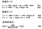
図2を参照すると、2つの電気化学反応(R)、R1及びR2は、本明細書で説明されたデュアル電気化学システムの充電モードにおいて生じる。運転中、充電モードの間は、電気は外部回路を通じて印加される。M(一般に希土類金属)は、水及び電子と反応してアノードで金属水素化物MHを生じ、水酸基イオンOH−を生じる。カソードでは、電解質中の水酸基イオンから酸素が発生する。この酸素は、カソードから大気中に排出され、もしくは、酸素は容器に収集され、その後放電モードでカソードに再循環して戻される。放電モードでデュアルモード電気化学システムによって発生した水は、再循環チャネルを通じてアノードに再循環して戻すことができ、そこで固体アノードを再充電するのに使用される。 Referring to FIG. 2, two electrochemical reactions (R), R1 and R2, occur in the charge mode of the dual electrochemical system described herein. During operation, during the charging mode, electricity is applied through an external circuit. M (generally a rare earth metal) reacts with water and electrons to produce a metal hydride MH at the anode, producing a hydroxyl ion OH − . At the cathode, oxygen is generated from hydroxyl ions in the electrolyte. This oxygen is exhausted from the cathode into the atmosphere, or the oxygen is collected in a container and then recycled back to the cathode in discharge mode. Water generated by the dual mode electrochemical system in discharge mode can be recycled back to the anode through a recirculation channel where it is used to recharge the solid anode.
図2に示されるように、放電モードでは、水素は金属水素化物から放出されて酸素と反応して電気と水を生成し、該酸素は放電プロセスの間に酸素含有発生源によって加えられる。反応R3においては、金属水素化物MHは、水酸基イオンと反応して水と電子とを生成する。水は、反応R4において酸素と反応し、電子は消費されて水酸基イオンを発生する。反応R5全体において、水収支はデュアルモード電気化学システムで保持される。これらの反応は、様々な可能性のある反応の原理の例証に過ぎない点を理解すべきである。デュアルモード電気化学装置の充放電はまた、異なる反応経路に対して実現することができる。充電モードにおいては、デュアルモード電気化学システムに電気エネルギが供給され、該システムは、電気分解装置と類似の働きをする。放電モードにおいては、デュアルモード電気化学システムにおいて電気エネルギが発生し、該システムは燃料電池として働く。 As shown in FIG. 2, in the discharge mode, hydrogen is released from the metal hydride and reacts with oxygen to produce electricity and water, which is added by an oxygen-containing source during the discharge process. In the reaction R3, the metal hydride MH reacts with hydroxyl ions to generate water and electrons. Water reacts with oxygen in reaction R4, and the electrons are consumed to generate hydroxyl ions. Throughout reaction R5, the water balance is maintained with a dual mode electrochemical system. It should be understood that these reactions are merely illustrative of the various possible reaction principles. Charge / discharge of a dual mode electrochemical device can also be realized for different reaction paths. In the charging mode, electrical energy is supplied to the dual mode electrochemical system, which acts like an electrolyzer. In the discharge mode, electrical energy is generated in a dual mode electrochemical system, which acts as a fuel cell.
水素源として上記で水が説明されているが、しかしながら、水は本技術の限定的な実施例であることを意味するものではない。他の実施例においては、水素の発生源は、とりわけ、メタノール、水酸化ホウ素ナトリウム、シクロヘキサノール及びフェニルアミンを含むことができる。アノードの寿命を延ばすためには、付加された水を濾過して全ての固体物を除去し、汚損を回避することができる。酸素を含む任意の酸化剤は、再充電プロセスで使用することができる。1つの実施形態においては、空気が酸化剤として使用される。幾つかの他の実施形態においては、純酸素が酸化剤として使用される。 Water has been described above as a hydrogen source, however, water is not meant to be a limiting example of the present technology. In other examples, the source of hydrogen can include methanol, sodium borohydride, cyclohexanol, and phenylamine, among others. To extend the life of the anode, the added water can be filtered to remove all solids and avoid fouling. Any oxidant, including oxygen, can be used in the recharging process. In one embodiment, air is used as the oxidant. In some other embodiments, pure oxygen is used as the oxidant.
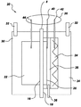
図3は、本技術による例示的なデュアルモード電気化学システム20の別の概略図である。この例示的なデュアルモード電気化学システム20は、水素を貯蔵可能なアノード22と、カソード24とを含む。実質的に電気絶縁されたイオン伝導性の膜8は、アノード22とカソード24との間に配置されている。デュアルモード電気化学システム20は更に電解質を含む。デュアルモード運転中、デュアルモード電気化学システム20は、第1のモードと第2のモードとで運転する。運転中、デュアルモード電気化学システム20の第1のモードの間、デュアルモード電気化学システム20に水及び電気が加えられる。デュアルモード電気化学システムは、電解質存在下で水を電解し、膜8の両側に水素と酸素とを発生させる。電気分解プロセスで発生した水素は、アノード22に貯蔵される。デュアル電気化学システムの第1のモードは、一般に充電モードと呼ばれ、水素が発生されてアノード22に貯蔵される。運転の第2のモードにおいては、デュアルモード電気化学システム20は燃料電池として運転し、酸化剤が導入されると、貯蔵された水素が膜8の両側で酸化剤と反応して化学反応を生じ、水と電気とを発生する。
FIG. 3 is another schematic diagram of an exemplary dual
図3に示されるように例示的なデュアルモード電気化学システム20は更に、膜8のカソード側18に隣接する触媒層28を含む。この触媒層28の機能は、酸素を触媒処理して水酸基イオンを発生させることである。この触媒層28は、限定ではないが、プラチナ、パラジウム、ルテニウム、銀、マンガン及びこれらの組み合わせを含む材料から構成することができる。幾つかの実施形態においては、触媒層は、MnO2及びLapCaqCoO3を含み、ここでp及びqは、0.2≦p≦0.8及び0.1≦q≦0.6として定義される。幾つかの他の実施形態においては、触媒層はLiMn2−rCorO4を含むみ、ここでrは、0.2≦r≦1.5として定義される。幾つかの他の実施形態においては、触媒層は、CaO、Ni(OH)2、NiO、CoO、KMnO4及びこれらの組み合わせを含む。触媒層としてプラチナが使用される実施形態においては、プラチナの表面は、最大の表面積量が酸素に露出されるようにされる。酸素分子は、触媒の存在下で還元され、外部回路から電子を受入れて、水素と反応する間水酸基イオンを発生し、その結果水を発生させる。この電気化学反応においては、2つの電極間に電位が生じる。
As shown in FIG. 3, the exemplary dual
アノード22に使用される材料は、上記セクションで説明された通りである。カソードは、導電性酸化物、ペロブスカイト、ドープLaMnO3、スズドープ酸化インジウム(In2O3)、ストロンチウムドープPrMnO3、Laフェライト、Laコバルタイト、RuO2−YSZ、及びこれらの組み合わせからなるグループから選択された材料を含むことができる。1つの実施形態においては、カソードは図3に示されるように、電流収集効率を改善するためメッシュ構造体を有するように構成される。カソード24はまた、触媒表面に酸素を分布させるよう働く、表面にエッチングされたチャネルを含むことができる。デュアルモード電気化学システム20は更に、酸素移送を強化するガス拡散層26を含むことができる。アノード22とカソード24とは、構造体30及び34によって保持されるように構成することができ、該構造体は導電性である。1つの実施形態においては、構造体30及び34は、炭素プレートで作られる。
The materials used for
運転中、アノード22及びカソード24は、複数の電流コレクタ32により充電及び放電モードの間の電流用内部経路を提供し、該電流コレクタは1つ又はそれ以上の外部負荷(図示されず)に接続されている。放電モードの間、電気化学システムによって生成された電子が利用可能であり、電流コレクタ32を介して1つ又はそれ以上の外部負荷に送られる。個々のシステム20の両端の動作電圧は、約1ボルト程度とすることができる。従って、十分な負荷電圧を得るために、複数の個々のシステム20を直列又は並列で配置することができる。
In operation,
デュアルモード電気化学装置は更に、図3の例示的な実施形態に示されたような圧力制御システム38を含むことができる。この圧力制御システム38は、圧力計測装置を含む。アノード側及びカソード側は、圧力放出システムに接続されている1つ又はそれ以上の圧力計測装置を有するように構成されている。圧力計測装置は、圧力ゲージ又はトランスデューサとすることができる。幾つかの実施形態においては、圧力計測装置は、圧力放出システムに接続されており、該システムは、弁又はラプチャディスクなどの安全解除装置を含むことができる。図3に示すように、アノード側の水素ポート44、並びに酸素及び空気ポート40は、圧力計測装置及び放出システムを含む。圧力制御システム38は、デュアルモード電気化学システム20の取り扱い及び運転を安全にするように構成されている。
The dual mode electrochemical device may further include a
図4は、放電プロセス中のデュアルモード電気化学装置の電位の変化を示す。該装置は、高い作動電圧で放電することができる。図4は、ポイント50で電位が急に変化しており、金属水素化物中に貯蔵された全ての水素が消費されたことを示している。
FIG. 4 shows the change in potential of the dual mode electrochemical device during the discharge process. The device can be discharged at a high operating voltage. FIG. 4 shows that the potential has changed abruptly at
本技術によれば、電気化学システム20は、輸送機関用途、携帯用電源、家庭用及び業務用発電、大出力発電及びこのようなシステムを使用することにより恩恵を受ける任意の他の用途で使用できる。燃料電池車は、開示されたデュアルモード電気化学システムによって給電される1つ又はそれ以上の電動機によって動力を供給することができる。
According to the present technology, the
本明細書に開示されたデュアルモード電気化学システムは、水素などの燃料を発生させ、内部に貯蔵することができる。充電運転中、水素はアノード材料中に貯蔵され、該水素は、デュアルモード電気化学システムが燃料電池として運転する放電モードの間に使用されて完全に使い尽くすことができる。開示されたデュアルモード電気化学システムは、再充電可能であり、どのような外部の水素発生源なしで運転することができる。 The dual mode electrochemical system disclosed herein can generate fuel such as hydrogen and store it internally. During the charge operation, hydrogen is stored in the anode material, which can be used up completely during the discharge mode when the dual mode electrochemical system operates as a fuel cell. The disclosed dual mode electrochemical system is rechargeable and can be operated without any external hydrogen source.
本発明が満たす様々な要求の実現の観点から本発明の種々の実施形態を説明してきた。これらの実施形態は、本発明の種々の実施形態の原理の例証に過ぎない点を理解すべきである。多くの修正及び改変は、本発明の精神及び範囲から逸脱することなく当業者には明らかであろう。なお、特許請求の範囲に記載された符号は、理解容易のためであってなんら発明の技術的範囲を実施例に限縮するものではない。 Various embodiments of the invention have been described in terms of fulfilling the various needs met by the invention. It should be understood that these embodiments are merely illustrative of the principles of various embodiments of the present invention. Many modifications and variations will be apparent to those skilled in the art without departing from the spirit and scope of the invention. In addition, the code | symbol described in the claim is for easy understanding, and does not limit the technical scope of an invention to an Example at all.
2 電気化学システム
4 第1の電極
6 第2の電極
8 膜
10 外部回路
11 充電回路
12 水
13 負荷
14 酸化剤
2
Claims (10)
水素を貯蔵可能な第1の電極(4)と、
第2の電極(6)と、
これらの間に介在された、実質的に電気絶縁し且つ実質的にイオン伝導性の膜(8)と、
電解質と、
を備え、
第1のモードにおいて、水と電気とが導入されると、前記デュアルモード電気化学システムは前記電解質存在下で前記水を電解して、前記膜(8)の両側で水素と酸素とを発生させ、前記水素は前記第1の電極(4)によって貯蔵され、第2のモードにおいて、前記第2の電極(6)に酸化性物質が導入されると、前記デュアルモード電気化学システムは、前記貯蔵された水素と前記酸化性物質とが前記膜(8)の両側で反応することによって水と電気とを発生させることを特徴とするシステム。 A dual mode electrochemical system,
A first electrode (4) capable of storing hydrogen;
A second electrode (6);
A substantially electrically insulating and substantially ion conductive membrane (8) interposed between them;
Electrolyte,
With
In the first mode, when water and electricity are introduced, the dual mode electrochemical system electrolyzes the water in the presence of the electrolyte to generate hydrogen and oxygen on both sides of the membrane (8). The hydrogen is stored by the first electrode (4), and in a second mode, when an oxidizing substance is introduced into the second electrode (6), the dual mode electrochemical system is A system characterized in that water and electricity are generated by the reaction between the generated hydrogen and the oxidizing substance on both sides of the membrane (8).
Applications Claiming Priority (1)
| Application Number | Priority Date | Filing Date | Title |
|---|---|---|---|
| US10/882,313 US7282294B2 (en) | 2004-07-02 | 2004-07-02 | Hydrogen storage-based rechargeable fuel cell system and method |
Publications (2)
| Publication Number | Publication Date |
|---|---|
| JP2006019302A true JP2006019302A (en) | 2006-01-19 |
| JP2006019302A5 JP2006019302A5 (en) | 2008-08-14 |
Family
ID=35514326
Family Applications (1)
| Application Number | Title | Priority Date | Filing Date |
|---|---|---|---|
| JP2005193608A Pending JP2006019302A (en) | 2004-07-02 | 2005-07-01 | Hydrogen storage-based rechargeable fuel cell system and method |
Country Status (4)
| Country | Link |
|---|---|
| US (1) | US7282294B2 (en) |
| JP (1) | JP2006019302A (en) |
| CN (1) | CN100530789C (en) |
| DE (1) | DE102005029563A1 (en) |
Cited By (1)
| Publication number | Priority date | Publication date | Assignee | Title |
|---|---|---|---|---|
| JP2019514190A (en) * | 2016-04-14 | 2019-05-30 | エヌイー.エム.イー.エスワイエス.エスアールエル | Rechargeable electrochemical device for electrical energy generation |
Families Citing this family (24)
| Publication number | Priority date | Publication date | Assignee | Title |
|---|---|---|---|---|
| US20040034177A1 (en) * | 2002-05-02 | 2004-02-19 | Jian Chen | Polymer and method for using the polymer for solubilizing nanotubes |
| CN1813023A (en) * | 2003-05-22 | 2006-08-02 | 塞威公司 | Nanocomposites and methods thereto |
| JP5254608B2 (en) * | 2004-04-13 | 2013-08-07 | ザイベックス パフォーマンス マテリアルズ、インク. | Method for synthesizing modular poly (phenylene ethylenin) and method for fine-tuning its electronic properties to functionalize nanomaterials |
| US7296576B2 (en) * | 2004-08-18 | 2007-11-20 | Zyvex Performance Materials, Llc | Polymers for enhanced solubility of nanomaterials, compositions and methods therefor |
| US7632582B2 (en) * | 2005-09-07 | 2009-12-15 | Ovonic Fuel Cell Company Llc | Method and apparatus for maintaining high voltage in a fuel cell |
| CN101410555A (en) | 2006-03-24 | 2009-04-15 | 通用汽车环球科技运作公司 | Apparatus and method for synthesis of alane |
| FI20060602A0 (en) * | 2006-06-19 | 2006-06-19 | Valtion Teknillinen | New thin film structures |
| US20080175781A1 (en) * | 2006-09-22 | 2008-07-24 | The Regents Of The University Of California | Bootstrap synthesis of boranes |
| US7927754B2 (en) * | 2006-10-26 | 2011-04-19 | GM Global Technology Operations LLC | Pressure relief feature for a fuel cell stack |
| US20080145721A1 (en) * | 2006-12-14 | 2008-06-19 | General Electric Company | Fuel cell apparatus and associated method |
| CN100463275C (en) * | 2007-07-13 | 2009-02-18 | 西安交通大学 | Borohydride alkaline dry cell |
| JP2009269811A (en) * | 2008-04-30 | 2009-11-19 | Hyundai Motor Co Ltd | Hydrogen generating apparatus |
| NZ598215A (en) * | 2009-08-17 | 2014-02-28 | Mioxide Mining Pty Ltd | Fuel cell |
| US9070936B2 (en) * | 2011-03-03 | 2015-06-30 | Jadavpur University | Thermal electrochemical cell |
| WO2013028911A1 (en) * | 2011-08-25 | 2013-02-28 | The Board Of Trustees Of The Leland Stanford Junior University | Catalysis controlled by interfacial electric fields |
| CN102427144B (en) * | 2011-11-29 | 2014-12-10 | 上海交通大学 | Regenerative fuel cell apparatus and system thereof |
| TW201403936A (en) * | 2012-07-13 | 2014-01-16 | shi-hang Zhou | Hydrogen-recyclable fuel cell |
| US9623204B2 (en) | 2012-08-20 | 2017-04-18 | Hydro Healer, Llc | Electrolysis system and apparatus for collecting hydrogen gas |
| EP4234484A3 (en) | 2013-06-14 | 2023-12-06 | USW Commercial Services Ltd. | Synthesis and hydrogen storage properties of manganese hydrides |
| EP4234483A3 (en) | 2014-06-13 | 2023-12-13 | USW Commercial Services Ltd. | Synthesis and hydrogen storage properties of novel metal hydrides |
| NL2014541B1 (en) * | 2015-03-27 | 2017-01-06 | W&F Beheer B V | Method for operating of a regenerative bipolar membrane fuel cell, and regenerative bipolar membrane fuel cell there for. |
| CN106784960B (en) * | 2016-12-30 | 2020-01-21 | 上海恒劲动力科技有限公司 | Integrated reversible fuel cell system |
| GB2566604B (en) * | 2017-08-04 | 2022-11-02 | Xergy Incorporated | Regenerative fuel cell |
| JP6929464B2 (en) * | 2017-12-26 | 2021-09-01 | 信越ポリマー株式会社 | Heat dissipation structure and battery with it |
Citations (5)
| Publication number | Priority date | Publication date | Assignee | Title |
|---|---|---|---|---|
| JPH06124734A (en) * | 1992-10-09 | 1994-05-06 | Hitachi Maxell Ltd | Oxygen catalytic electrode and air cell using the electrode |
| JPH06163064A (en) * | 1992-11-18 | 1994-06-10 | Kansai Electric Power Co Inc:The | Power storing device |
| JPH07289903A (en) * | 1994-04-28 | 1995-11-07 | Aisin Seiki Co Ltd | Catalyst for oxygen reducing electrode |
| JP2003526890A (en) * | 2000-03-13 | 2003-09-09 | エナージー コンバーション デバイセス インコーポレイテッド | New alkaline fuel cell |
| JP2006509163A (en) * | 2002-12-04 | 2006-03-16 | フューエルセル・テクノロジーズ・インコーポレーテッド | Hydrogen storage, delivery and recovery system |
Family Cites Families (14)
| Publication number | Priority date | Publication date | Assignee | Title |
|---|---|---|---|---|
| DE1934974C3 (en) | 1969-07-10 | 1974-06-06 | Deutsche Automobilgesellschaft Mbh, 7000 Stuttgart-Untertuerkheim | Galvanic storage unit consisting of a fuel cell device and an accumulator device with a common negative electrode that can be connected in parallel |
| JPS5948872B2 (en) * | 1978-02-20 | 1984-11-29 | クロリンエンジニアズ株式会社 | Electrolytic cathode and its manufacturing method |
| US4839247A (en) * | 1987-11-13 | 1989-06-13 | International Fuel Cells Corporation | Static regenerative fuel cell system for use in space |
| JPH05242906A (en) | 1992-02-26 | 1993-09-21 | Sanyo Electric Co Ltd | Air-metal hydride secondary battery |
| US5306577A (en) * | 1992-07-15 | 1994-04-26 | Rockwell International Corporation | Regenerative fuel cell system |
| JP3272075B2 (en) | 1993-01-25 | 2002-04-08 | 三洋電機株式会社 | Air-hydride batteries |
| US5589285A (en) * | 1993-09-09 | 1996-12-31 | Technology Management, Inc. | Electrochemical apparatus and process |
| US6569298B2 (en) * | 2000-06-05 | 2003-05-27 | Walter Roberto Merida-Donis | Apparatus for integrated water deionization, electrolytic hydrogen production, and electrochemical power generation |
| US6613215B2 (en) * | 2000-09-27 | 2003-09-02 | Proton Energy Systems, Inc. | Method for electrolysis of water using a polytetrafluoroethylene supported membrane in electrolysis cells |
| JP2002184474A (en) | 2000-12-14 | 2002-06-28 | Hitachi Maxell Ltd | Air battery |
| DE10213134A1 (en) * | 2002-03-23 | 2003-10-09 | Daimler Chrysler Ag | Fuel cell and method for cold starting such a fuel cell |
| US7011768B2 (en) * | 2002-07-10 | 2006-03-14 | Fuelsell Technologies, Inc. | Methods for hydrogen storage using doped alanate compositions |
| US7198867B2 (en) * | 2002-09-17 | 2007-04-03 | Diffusion Science, Inc. | Electrochemical generation, storage and reaction of hydrogen and oxygen |
| US20050136312A1 (en) * | 2003-12-22 | 2005-06-23 | General Electric Company | Compliant fuel cell system |
-
2004
- 2004-07-02 US US10/882,313 patent/US7282294B2/en not_active Expired - Fee Related
-
2005
- 2005-06-23 DE DE102005029563A patent/DE102005029563A1/en not_active Withdrawn
- 2005-07-01 JP JP2005193608A patent/JP2006019302A/en active Pending
- 2005-07-04 CN CNB2005100822488A patent/CN100530789C/en not_active Expired - Fee Related
Patent Citations (5)
| Publication number | Priority date | Publication date | Assignee | Title |
|---|---|---|---|---|
| JPH06124734A (en) * | 1992-10-09 | 1994-05-06 | Hitachi Maxell Ltd | Oxygen catalytic electrode and air cell using the electrode |
| JPH06163064A (en) * | 1992-11-18 | 1994-06-10 | Kansai Electric Power Co Inc:The | Power storing device |
| JPH07289903A (en) * | 1994-04-28 | 1995-11-07 | Aisin Seiki Co Ltd | Catalyst for oxygen reducing electrode |
| JP2003526890A (en) * | 2000-03-13 | 2003-09-09 | エナージー コンバーション デバイセス インコーポレイテッド | New alkaline fuel cell |
| JP2006509163A (en) * | 2002-12-04 | 2006-03-16 | フューエルセル・テクノロジーズ・インコーポレーテッド | Hydrogen storage, delivery and recovery system |
Cited By (1)
| Publication number | Priority date | Publication date | Assignee | Title |
|---|---|---|---|---|
| JP2019514190A (en) * | 2016-04-14 | 2019-05-30 | エヌイー.エム.イー.エスワイエス.エスアールエル | Rechargeable electrochemical device for electrical energy generation |
Also Published As
| Publication number | Publication date |
|---|---|
| US20060003203A1 (en) | 2006-01-05 |
| DE102005029563A1 (en) | 2006-02-16 |
| US7282294B2 (en) | 2007-10-16 |
| CN100530789C (en) | 2009-08-19 |
| CN1716668A (en) | 2006-01-04 |
Similar Documents
| Publication | Publication Date | Title |
|---|---|---|
| JP2006019302A (en) | Hydrogen storage-based rechargeable fuel cell system and method | |
| US6613471B2 (en) | Active material for fuel cell anodes incorporating an additive for precharging/activation thereof | |
| TW522602B (en) | Catalytic hydrogen storage composite material and fuel cell employing same | |
| US6447942B1 (en) | Alkaline fuel cell | |
| Raman et al. | A direct borohydride/hydrogen peroxide fuel cell with reduced alkali crossover | |
| WO2002041432A1 (en) | Fuel cell | |
| Zhang et al. | An overview of non-noble metal electrocatalysts and their associated air cathodes for Mg-air batteries | |
| EP1661199A2 (en) | Hydrogen storage-based rechargeable fuel cell system | |
| US6828057B2 (en) | Fuel cell with framed electrodes | |
| US20030203273A1 (en) | Fuel cell with overmolded electrode assemblies | |
| US6703156B2 (en) | Fuel cell cathode utilizing multiple redox couples | |
| WO2019144751A1 (en) | Liquid metal fuel cell | |
| US6777125B2 (en) | Fuel cell cathode with redox couple | |
| US7033699B2 (en) | Fuel cell cathodes and their fuel cells | |
| US6926986B2 (en) | Fuel cell with encapsulated electrodes | |
| US6933072B2 (en) | Parallel flow fuel cell | |
| Panayiotou et al. | Solar hydrogen production and storage techniques | |
| Sherazi et al. | 2D Nanomaterials in Flexible Fuel Cells | |
| Lamy | Principle of Low‐temperature Fuel Cells Using an Ionic Membrane | |
| Van den Broeck | Research, development, and demonstration of alkaline fuel cell systems | |
| Ng et al. | HYDROGEN ENERGY AND FUEL CELL POWER PACKS | |
| Khade | Fuel cell technologies and applications | |
| Heinzel | Fuel cells and hydrogen technology | |
| Eskander | Recent Developments in Fuel Cells and Hydrogen Storage Methods Using Nanotechnology | |
| Jindal et al. | Solid-State Hydrogen Storage within a Proton Battery and Its Performance Analysis with Different Catalyst Loadings |
Legal Events
| Date | Code | Title | Description |
|---|---|---|---|
| A521 | Request for written amendment filed |
Free format text: JAPANESE INTERMEDIATE CODE: A523 Effective date: 20080701 |
|
| A621 | Written request for application examination |
Free format text: JAPANESE INTERMEDIATE CODE: A621 Effective date: 20080701 |
|
| RD02 | Notification of acceptance of power of attorney |
Free format text: JAPANESE INTERMEDIATE CODE: A7422 Effective date: 20101203 |
|
| RD04 | Notification of resignation of power of attorney |
Free format text: JAPANESE INTERMEDIATE CODE: A7424 Effective date: 20101203 |
|
| A131 | Notification of reasons for refusal |
Free format text: JAPANESE INTERMEDIATE CODE: A131 Effective date: 20110809 |
|
| A601 | Written request for extension of time |
Free format text: JAPANESE INTERMEDIATE CODE: A601 Effective date: 20111109 |
|
| A602 | Written permission of extension of time |
Free format text: JAPANESE INTERMEDIATE CODE: A602 Effective date: 20111114 |
|
| A521 | Request for written amendment filed |
Free format text: JAPANESE INTERMEDIATE CODE: A523 Effective date: 20120209 |
|
| A02 | Decision of refusal |
Free format text: JAPANESE INTERMEDIATE CODE: A02 Effective date: 20121009 |
|
| A521 | Request for written amendment filed |
Free format text: JAPANESE INTERMEDIATE CODE: A523 Effective date: 20130208 |
|
| A911 | Transfer to examiner for re-examination before appeal (zenchi) |
Free format text: JAPANESE INTERMEDIATE CODE: A911 Effective date: 20130329 |
|
| A131 | Notification of reasons for refusal |
Free format text: JAPANESE INTERMEDIATE CODE: A131 Effective date: 20130507 |
|
| A601 | Written request for extension of time |
Free format text: JAPANESE INTERMEDIATE CODE: A601 Effective date: 20130807 |
|
| A602 | Written permission of extension of time |
Free format text: JAPANESE INTERMEDIATE CODE: A602 Effective date: 20130812 |
|
| A601 | Written request for extension of time |
Free format text: JAPANESE INTERMEDIATE CODE: A601 Effective date: 20130906 |
|
| A602 | Written permission of extension of time |
Free format text: JAPANESE INTERMEDIATE CODE: A602 Effective date: 20130911 |
|
| A601 | Written request for extension of time |
Free format text: JAPANESE INTERMEDIATE CODE: A601 Effective date: 20131007 |
|
| A602 | Written permission of extension of time |
Free format text: JAPANESE INTERMEDIATE CODE: A602 Effective date: 20131010 |
|
| A521 | Request for written amendment filed |
Free format text: JAPANESE INTERMEDIATE CODE: A523 Effective date: 20131107 |
|
| A912 | Re-examination (zenchi) completed and case transferred to appeal board |
Free format text: JAPANESE INTERMEDIATE CODE: A912 Effective date: 20140110 |
|
| A601 | Written request for extension of time |
Free format text: JAPANESE INTERMEDIATE CODE: A601 Effective date: 20140502 |
|
| A602 | Written permission of extension of time |
Free format text: JAPANESE INTERMEDIATE CODE: A602 Effective date: 20140509 |
|
| A601 | Written request for extension of time |
Free format text: JAPANESE INTERMEDIATE CODE: A601 Effective date: 20140602 |
|
| A602 | Written permission of extension of time |
Free format text: JAPANESE INTERMEDIATE CODE: A602 Effective date: 20140605 |
|
| A601 | Written request for extension of time |
Free format text: JAPANESE INTERMEDIATE CODE: A601 Effective date: 20140704 |
|
| A602 | Written permission of extension of time |
Free format text: JAPANESE INTERMEDIATE CODE: A602 Effective date: 20140709 |
|
| A601 | Written request for extension of time |
Free format text: JAPANESE INTERMEDIATE CODE: A601 Effective date: 20141216 |
|
| A602 | Written permission of extension of time |
Free format text: JAPANESE INTERMEDIATE CODE: A602 Effective date: 20141219 |
|
| A601 | Written request for extension of time |
Free format text: JAPANESE INTERMEDIATE CODE: A601 Effective date: 20150123 |
|
| A601 | Written request for extension of time |
Free format text: JAPANESE INTERMEDIATE CODE: A601 Effective date: 20150223 |
|
| A521 | Request for written amendment filed |
Free format text: JAPANESE INTERMEDIATE CODE: A523 Effective date: 20150324 |