JP2006016809A - Remote locking/unlocking control device for fitting group - Google Patents
Remote locking/unlocking control device for fitting group Download PDFInfo
- Publication number
- JP2006016809A JP2006016809A JP2004194116A JP2004194116A JP2006016809A JP 2006016809 A JP2006016809 A JP 2006016809A JP 2004194116 A JP2004194116 A JP 2004194116A JP 2004194116 A JP2004194116 A JP 2004194116A JP 2006016809 A JP2006016809 A JP 2006016809A
- Authority
- JP
- Japan
- Prior art keywords
- locking
- fixture
- unlocking
- shelf
- lamp
- Prior art date
- Legal status (The legal status is an assumption and is not a legal conclusion. Google has not performed a legal analysis and makes no representation as to the accuracy of the status listed.)
- Pending
Links
Images


Landscapes
- Selective Calling Equipment (AREA)
Abstract
Description
本発明は、少なくとも内部に収容部を有するとともに、該収容部へのアプローチを規制する規制部材と、該規制部材の開放を抑止又は該抑止を解除する施解錠手段と、を備えた複数の什器からなる什器群の施解錠を、遠隔操作器から送信される旋錠或いは解錠信号に基づいて作動する制御手段を介して、遠隔にて実施可能な遠隔施解錠装置に関する。 The present invention has a housing having at least an inner portion, a restriction member for restricting an approach to the housing portion, and a locking / unlocking means for inhibiting the release of the restriction member or releasing the inhibition. It is related with the remote locking / unlocking apparatus which can be remotely implemented through the control means which act | operates based on the locking or unlocking signal transmitted from a remote controller.
従来、上下複数段で左右方向に背中合わせに並設された2列の複数の什器からなる什器群の施解錠を、遠隔操作器より遠隔にて実施可能な什器群の遠隔施解錠装置が開示されおり、複数の什器からなる什器群の施解錠を遠隔操作器より操作して、各什器の全ての施解錠を行っていた(例えば、特許文献1参照)。 Conventionally, there has been disclosed a remote locking / unlocking device for a group of fixtures capable of remotely locking and unlocking a group of fixtures composed of a plurality of rows of fixtures arranged side by side in a horizontal direction in a plurality of upper and lower stages. In addition, all the fixtures have been locked / unlocked by operating the lock / unlock of the fixture group including a plurality of fixtures from the remote controller (see, for example, Patent Document 1).
このような従来の背中合わせに什器群が配列されているものは、背面側の什器の収容部内にある物品の出し入れに際し、廻り込まなければならないといった不便さがあった。そこで、後列を固定棚にし、前方列を移動棚とした棚装置が既に開発されている。この棚装置において、固定棚の什器の収容部に物品等の出し入れを行うには移動棚を左右方向いずれか一方側に移動させることで、収容部へのアプローチが可能な構成になっていた。 Such a conventional back-to-back arrangement of fixtures has the inconvenience of having to go around in and out of articles in the fixture housing on the back side. Therefore, a shelf apparatus has been developed in which the rear row is a fixed shelf and the front row is a moving shelf. In this shelf apparatus, in order to load and remove articles and the like into and from the storage portion of the fixture of the fixed shelf, the movable shelf is moved to either one of the left and right directions so that the approach to the storage portion is possible.
上記した棚装置では、前方列の移動棚を左右方向に一方側によせた時に、移動棚と重なる固定棚の什器の収容部へのアプローチが規制されるため、什器群を施錠する場合に、移動棚と重なる固定棚の什器に対しては施錠しない代わりに、移動棚を施錠しない固定棚の什器に重なるように、常に所定の位置に移動させたのち位置固定させてから、個々に所要の各什器に施錠を行っており、絶えず移動棚を所定位置に固定しなければならないという煩わしさがあった。 In the above-described shelf device, when the front row of moving shelves is placed on one side in the left-right direction, the approach to the storage unit of the fixture of the fixed shelf that overlaps the moving shelf is regulated, so when locking the fixture group, Instead of locking the fixed shelf fixture that overlaps the moving shelf, always move it to a predetermined position so that it overlaps with the fixed shelf fixture that is not locked, then fix the position and then individually Each fixture was locked, and there was annoyance that the moving shelf had to be constantly fixed at a predetermined position.
本発明は、移動棚が設けられた棚装置においても、移動棚を所定位置に移動させて固定することなく、遠隔操作器による操作により各什器すべての施解錠を一斉に行うことができる什器群の遠隔施解錠装置を提供することを目的とする。 The present invention provides a group of fixtures that can perform unlocking and unlocking of all fixtures at the same time by operation with a remote controller without moving and fixing the movable shelf to a predetermined position even in a shelf device provided with a movable shelf. An object of the present invention is to provide a remote locking / unlocking device.
上記課題を解決するために、本発明の請求項1に記載の什器群の遠隔施解錠装置は、少なくとも内部に収容部を有するとともに、該収容部へのアプローチを規制する規制部材と、該規制部材の開放を抑止又は該抑止を解除する施解錠手段と、を備えた複数の什器からなる什器群の施解錠を、遠隔操作器から送信される旋錠或いは解錠信号に基づいて作動する制御手段を介して、遠隔にて実施可能な遠隔施解錠装置であって、前記什器群は前後に整列した複数列の棚からなり、最後列の棚は固定棚として構成され、前記固定棚前方の複数列の棚は左右方向に移動可能な移動棚として構成され、前記移動棚は什器毎に区分けされ、前記遠隔操作器の操作により、各什器すべての施解錠手段が制御されることを特徴としている。
この特徴によれば、遠隔施解錠装置の固定棚および移動棚の全ての什器に規制部材と施解錠手段と制御手段とを設けたことにより、遠隔操作器の操作で移動棚の位置に関係なく各什器すべての施解錠手段が制御される。
In order to solve the above-mentioned problem, the remote locking and unlocking device for a fixture group according to
According to this feature, all the fixtures on the fixed shelf and the movable shelf of the remote locking / unlocking device are provided with the regulating member, the locking / unlocking means, and the control means, so that the operation of the remote controller can be used regardless of the position of the movable shelf. The locking / unlocking means for each fixture is controlled.
本発明の請求項2に記載の什器群の遠隔施解錠装置は、請求項1に記載の什器群の遠隔施解錠装置であって、最前列の移動棚を除く棚の什器には引戸が設けられ、該引戸に前記規制部材が備えられていることを特徴としている。
この特徴によれば、最前列の移動棚を除く各列の移動棚と最後列の固定棚との各什器の規制部材を引戸にしたことにより、引戸を開扉した状態で前方列の移動棚を移動させても、前方の移動棚が引戸に当接することはない。
The remote lock-unlocking device for the fixture group according to
According to this feature, since the regulating members of the fixtures of the moving shelves in each row except the moving shelves in the front row and the fixed shelves in the last row are used as sliding doors, the moving shelves in the front row with the sliding doors opened. Even if is moved, the moving shelf in front does not come into contact with the sliding door.
本発明の請求項3に記載の什器群の遠隔施解錠装置は、請求項1または2に記載の什器群の遠隔施解錠装置であって、前記各什器には施解錠状態を表示する表示ランプが設けられていることを特徴としている。
この特徴によれば、各什器には規制部材の施解錠状態を表示する表示ランプが設けられることで、各什器の規制部材の施解錠状態を簡単に認識できる。
The remote locking / unlocking device for a fixture group according to
According to this feature, each fixture is provided with a display lamp that displays the locking / unlocking state of the restricting member, so that the locking / unlocking state of the restricting member of each fixture can be easily recognized.
本発明の請求項4に記載の什器群の遠隔施解錠装置は、請求項1乃至3のいずれかに記載の什器群の遠隔施解錠装置であって、最前列の移動棚における什器の前面に、前記後方の各什器の施解錠状態を表示する表示ランプが設けられていることを特徴としている。
この特徴によれば、最前列の移動棚の前面には後方列の棚の各什器における施解錠状態を表示する表示ランプが設けられているため、最前列の移動棚の後方に重なる各什器の施解錠状態を表示する表示ランプが隠蔽されていても、常に後方列の棚の各什器における施解錠状態を認識できる。
The remote lock-unlocking device for the fixture group according to claim 4 of the present invention is the remote lock-unlocking device for the fixture group according to any one of
According to this feature, a display lamp for displaying the locking / unlocking state of each fixture in the rear row shelf is provided on the front face of the front row moving shelf. Even if the display lamp for displaying the locked / unlocked state is concealed, the locked / unlocked state of each fixture in the rear row of shelves can always be recognized.
本発明の請求項5に記載の什器群の遠隔施解錠装置は、請求項4に記載の什器群の遠隔施解錠装置であって、前記後方の各什器の施解錠状態を表示する表示ランプは最前列の移動棚の1つに設けられていることを特徴としている。
この特徴によれば、最前列の1つの移動棚に設けられた表示ランプを見るだけで、後方列の各什器の施解錠状態を一目で視認できる。
The remote locking / unlocking device for the fixture group according to
According to this feature, the locking / unlocking state of each fixture in the rear row can be seen at a glance by simply looking at the display lamp provided on one moving shelf in the front row.
本発明の実施例を以下に説明する。 Examples of the present invention will be described below.
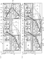
図1(a)は、本発明の実施例における什器群の遠隔施解錠装置の全体像を示す斜視図であり、図1(b)は、前方列の移動棚を図1(a)の状態から移動させた斜視図であり、図2は、遠隔操作器から表示ランプまでの配線状態を示す概略斜視図であり、図3は、制御ユニットと配線の構造を示す平面図であり、図4は、遠隔施解錠装置の平面図であり、図5(a)は、移動棚の移動時におけるパンタグラフ式支持部材の可動および配線の状態を示す平面図であり、図5(b)は、移動棚の移動終了におけるパンタグラフ式支持部材と配線の状態を示す平面図であり、図6(a)は、上下棚毎に設けられた各什器の解錠状態における各什器ランプ及び遠隔操作器における旋錠確認ランプの表示状況を示す概略図であり、図6(b)は、施解錠の一斉旋錠状態における各ランプの表示状況を示す概略図であり、図7(a)は、一部の什器の開扉状態における各什器ランプ及び遠隔操作器における旋錠確認ランプの表示状況を示す概略図であり、図7(b)は、施解錠の一斉旋錠不能状態における各ランプの表示状況を示す概略図である。 Fig.1 (a) is a perspective view which shows the whole image of the remote locking / unlocking device of the fixture group in the Example of this invention, FIG.1 (b) shows the movement shelf of a front row in the state of Fig.1 (a). 2 is a schematic perspective view showing a wiring state from the remote controller to the display lamp, and FIG. 3 is a plan view showing the structure of the control unit and the wiring. Fig. 5 (a) is a plan view of the remote locking / unlocking device, Fig. 5 (a) is a plan view showing the movable and wiring state of the pantograph-type support member when the movable shelf is moved, and Fig. 5 (b) is a moving diagram. FIG. 6A is a plan view showing the state of the pantograph-type support member and the wiring at the end of the movement of the shelf, and FIG. 6A is a diagram of each fixture lamp in the unlocked state of each fixture provided for each of the upper and lower shelves and the locking in the remote controller FIG. 6B is a schematic diagram showing the display status of the confirmation lamp, and FIG. It is the schematic which shows the display condition of each lamp | ramp in the simultaneous locked state of FIG. 7, Fig.7 (a) is a schematic which shows the display condition of the lock confirmation lamp | ramp in each fixture lamp in a door open state of some fixtures, and a remote control device. FIG. 7B is a schematic diagram showing the display status of each lamp in a state where locking and unlocking cannot be performed simultaneously.
この遠隔施解錠装置は、主に企業の各種書類の管理室や倉庫に設置されており、各棚を構成する多段の什器毎に設けられた旋解錠手段を、後述において説明する遠隔操作器により制御可能になっている。 This remote locking / unlocking device is mainly installed in a management room or warehouse of various corporate documents, and a remote control device described later will be provided for the locking / unlocking means provided for each multi-stage fixture constituting each shelf. Can be controlled.
図1(a)に示されるように、遠隔施解錠装置1は主に複数の棚装置(本実施例では5つ)と遠隔操作器15により構成されており、これらは載置台2に設置されている。載置台2の前方には左右方向に2本の移動レール3が敷設され、2つの棚装置である移動棚11、12が移動レール3に沿って移動可能に載置されており、図1(b)に示されるように移動棚11、12が左右方向に移動できるようになっている。
As shown in FIG. 1 (a), the remote locking /
載置台2の後方には、3つの棚装置である固定棚6、7、8が位置固定され、固定棚6の左側方には遠隔操作器15が位置固定されている。遠隔操作器15の正面の中間部には、施解錠確認ランプ16と施解錠釦17が設けられ、下部には電源表示ランプ18と電源キースイッチ19が設けられている。遠隔施解錠装置1の起動または終了は、電源キースイッチ19の押操作により制御を行うことができ、電源キースイッチ19のON状態の場合には電源表示ランプ18が点灯され、電源キースイッチ19のOFF状態の場合には電源表示ランプ18が消灯される。
The fixed
移動棚11、12は上下段にそれぞれ設けられた上段什器13と下段什器14から構成され、各什器毎に収容部へのアプローチが規制できる従来公知の両開き式扉や引出し(規制部材)が備えられている。同様に固定棚6、7、8も上段什器9と下段什器10から構成され、各什器毎に収容部へのアプローチが規制できる従来公知の引戸(規制部材)が備えられている。規制部材にアプローチの規制がされていない場合には、各什器9、10、13、14の扉に形成された手掛部から扉を開放して、収容部にアプローチでき書類・書籍やファイル等の格納を行えるようになっている。しかも、固定棚6、7、8の扉は引戸構造となっているので、移動棚11、12を左右方向に繰り返し移動させた場合でも当接して破損させることはない。
The
移動棚11の前端上部には表示板23が立設されており、後述において詳述する後列左方上段什器用ランプ24と後列左方下段什器用ランプ25を上下に設けており、同様に移動棚12の前端上部には表示板23が立設され、中央部の上下に後列中央上段什器用ランプ24’と後列中央下段什器用ランプ25’、右端部の上下に後列右方上段什器用ランプ24’’と後列右方下段什器用ランプ25’’がそれぞれ設けられている。固定棚6,7,8の上段什器9の上部前面には転倒防止レール4が左右方向に設けられ、移動棚11、12の上部背面に設けられた図示しない転倒防止突条が転倒防止レール4に摺動可能に係合され地震等による転倒が防止されている。
A
固定棚6、7、8および移動棚11、12の上段什器9、13には、それぞれ上段什器ランプ26と、電子錠機能を備えた上段施解錠装置(施解錠手段)27が設けられており、同様に、固定棚6、7、8および移動棚11、12の下段什器10、14には、それぞれ下段什器ランプ28と、電子錠機能を備えた下段施解錠装置(施解錠手段)29が設けられている。これら上下段施解錠装置27,29は扉の開放を抑止又は抑止の解除を行う係止部材47(図1において破線で表示)を含み、施解錠装置が施開錠信号を受けるか、マニュアルキーで施開錠操作されることにより、係止部材47を作動して扉の開放を抑止又は抑止の解除を行うことができる。
The
固定棚6の上面6aには後述において詳述する制御ユニット31’が設置され、固定棚7、8の上面7a、8aには後述において詳述する制御ユニット31、31’がそれぞれ設置されている。固定棚7の上面7aから移動棚11の上面11aに後述する配線支持部材であるパンタグラフ式支持部材37が架設されており、固定棚8の上面8aから移動棚12の上面12aにも同様のパンタグラフ式支持部材37’が架設されている。
A
上段施解錠装置27および下段施解錠装置29が旋錠されると、それぞれ対応する係止部材47が係止作用して、各々の扉の開扉が不能となり(扉の開放が抑止・・・規制部材へのアプローチが規制される)、上段施解錠装置27および下段施解錠装置29が解錠されると、それぞれ対応する係止部材47の係止作用が解除され(扉の開放の抑止の解除)、各々の扉の開扉が可能となる。扉の開扉不能状態においては、上段什器ランプ26および下段什器ランプ28が消灯され、扉の開扉可能状態においては、上段什器ランプ26および下段什器ランプ28が点灯された状態になる。
When the upper-stage locking / unlocking
上段施解錠装置27および下段施解錠装置29は、手動の鍵操作によって外部から施解錠を行うこともできるが、一斉に行う場合には、遠隔操作器15の施解錠釦17の操作による旋錠信号に基づいて、上段施解錠装置27および下段施解錠装置29の旋錠が行われ、扉の開扉を可能にするには再度、施解錠釦17の操作による解錠信号に基づいて、上段施解錠装置27および下段施解錠装置29が解錠される。
The upper locking / unlocking
上記において説明した各固定棚6、7、8および移動棚11、12に設けられた上段什器ランプ26、下段什器ランプ28、上段施解錠装置27、下段施解錠装置29、後列上段什器ランプ24、24’、24’’、後列下段什器ランプ25、25’、25’’、制御ユニット31、31’と、遠隔操作器15の施解錠確認ランプ16、施解錠釦17、電源表示ランプ18、電源キースイッチ19の配線接続について以下に説明する。
図2に示されるように、固定棚6、7、8に設けられた上段什器ランプ26、下段什器ランプ28、上段施解錠装置27、下段施解錠装置29には、旋錠信号および解錠信号等の各種信号の送受信を行う信号ケーブルと、電力を供給する給電ケーブルと、を含む通信ケーブル5が各々接続され什器内に内部配線されており、配線孔9cを介して各固定棚6、7、8の上面6a、7a、8aに設けられた制御ユニット31’に接続され、固定棚7、8の制御ユニット31’と隣接する制御ユニット31も通信ケーブル5で接続されている。
As shown in FIG. 2, an upper
同様に、移動棚11、12に設けられた上段什器ランプ26、下段什器ランプ28、上段施解錠装置27、下段施解錠装置29には、通信ケーブル5が各々接続され什器内に内部配線されており、配線孔13cを介してパンタグラフ式支持部材37、37’に配線され、固定棚7、8各上面7a、8aに設けられた制御ユニット31に接続されている。
Similarly, the
同じく、移動棚11の表示板23に設けられた後列左方上段什器用ランプ24と後列左方下段什器用ランプ25にも通信ケーブル5が各々接続されており、パンタグラフ式支持部材37を介して制御ユニット31に接続され、移動棚12の表示板23に設けられた後列上段什器ランプ24’、24’’と後列下段什器ランプ25’、25’’にも通信ケーブル5が各々接続されており、パンタグラフ式支持部材37’を介して、制御ユニット31に接続されている。
Similarly, a
固定棚8の制御ユニット31と固定棚7の制御ユニット31’は通信ケーブル5で接続され、固定棚7の制御ユニット31と固定棚6の制御ユニット31’は通信ケーブル5で接続されている。固定棚6の制御ユニット31’には別途通信ケーブル5が接続され、遠隔操作器15に設けられた後述のコントローラユニット20に接続されている。
The
遠隔操作器15の施解錠確認ランプ16、施解錠釦17、電源表示ランプ18、電源キースイッチ19には、通信ケーブル5が接続され内部配線されて、内部に設けられたコントローラユニット20に接続されている。遠隔操作器15の下部には電源供給用のACアダプター21が設置されコントローラユニット20に接続されている。つまり、施解錠確認ランプ16、施解錠釦17、電源表示ランプ18、電源キースイッチ19からの旋錠信号および解錠信号等の各種信号の制御およびACアダプター21からの給電制御がコントローラユニット20により行われる構成となっている。
A
なお、固定棚6、7、8および移動棚11、12の上部の外周には、遮蔽板22が上方に立設され取り付けられており、制御ユニット31、31’や通信ケーブル5の配線、パンタグラフ式支持部材37、37’を外部から露見させない構成になっており、外部からの見栄えが良くなるだけでなく、制御ユニット31、31’や通信ケーブル5を外部から保護できる(図1参照)。
In addition, a shielding
次いで、制御ユニット31、31’について詳細に説明すると、まず図3に示される制御ユニット31、31’は、基板32に旋錠信号および解錠信号等の各種信号の制御が行われるMPU33、各什器毎9、10、13、14に対応して固有に番号(ID)が設定される設定スイッチ34、左右に2箇所に通信ケーブル5が接続される接続コネクタ35、36が、それぞれ設けられ、図示しない透明プラスチック製の保護カバーで保護されている。
Next, the
制御ユニット31の左方の接続コネクタ35には、移動棚11、12の上段什器13に設けられた上段什器ランプ26、上段施解錠装置27、表示板23に設けられた後列上段什器用ランプ24、24’、24’’、後列下段什器等ランプ25、25’、25’’、からの通信ケーブル5がそれぞれ接続されている。右方の接続コネクタ35には、移動棚11、12の下段什器14に設けられた下段什器ランプ28、下段施解錠装置29、からの通信ケーブル5がそれぞれ接続されている。
The
制御ユニット31’の右方の接続コネクタ35には、固定棚6、7、8の各上段什器9に設けられた上段什器ランプ26、上段施解錠装置27からの通信ケーブル5、がそれぞれ接続されており、左方の接続コネクタ35には、固定棚6、7、8の下段什器10に設けられた下段什器ランプ28、下段施解錠装置29からの通信ケーブル5、がそれぞれ接続されている。
The
制御ユニット31の左方の接続コネクタ36に接続される通信ケーブル5は、制御ユニット31’の右方の接続コネクタ36に接続されおり、制御ユニット31の右方の接続コネクタ36に接続される通信ケーブル5は、隣接する制御ユニット31’の左方の接続コネクタ36に接続される。
The
したがって、固定棚7に載置した制御ユニット31によって移動棚11の上段什器ランプ26、上段施解錠装置27、下段什器ランプ28、下段施解錠装置29、後列左方上段什器用ランプ24、後列左方下段什器用ランプ25の制御が行われ、固定棚8に載置した制御ユニット31によって移動棚12の上段什器ランプ26、上段施解錠装置27、下段什器ランプ28、下段施解錠装置29、後列の中央と右方上段什器用ランプ24’、24’’、後列の中央と右方下段什器用ランプ25’、25’’の制御が行われる。そして、各固定棚6、7、8毎に設けられた制御ユニット31’によって、それぞれ対応する固定棚の什器の上段什器ランプ26、上段施解錠装置27、下段什器ランプ28、下段施解錠装置29、の制御が行われる。
Therefore, the
このように、1台の制御ユニット31で一つの移動棚の上下に重なる上段什器13と下段什器14の制御を行うことができ、1台の制御ユニット31’で一つの固定棚の上下に重なる上段什器9と下段什器10の制御を行うことができるので、固定棚の上面の省スペース化が図れる。
In this way, it is possible to control the
また、制御ユニット31、31’を固定棚6、7、8の最上部に位置する上段什器9の上面6a、7a、8aに設けたことにより、制御ユニット31、31’の着脱を固定棚6、7、8の最上部から簡便に行えるとともに、制御ユニット31、31’や、その周囲の通信ケーブル5等のメンテナンスも容易に行える。
Further, the
次に、パンタグラフ式支持部材37、37’について具体的に説明する。図4に示されるように、パンタグラフ式支持部材37、37’は、配線支持部材である2本の配線ダクト38、39から主に構成されている。配線ダクト38、39には図示しない軸孔を設けた枢着部38a、39aが形成され、軸40で互いの枢着部38a、39aが回動可能に軸支されており、軸40を中心に互いの配線ダクト38、39を屈曲させ、または伸長させることが可能な屈曲自在性を有している。配線ダクト38、39の他端内側には上下に延設された枢着部材41、42の上部がそれぞれ溶接されている。
Next, the pantograph-
配線ダクト38、39は、金属スチール材の折り曲げ加工で底板38x、39xと2つの側板38y、39yを形成させ上方に開口するように構成されているので、配線ダクト38、39の開口から通信ケーブル5を容易に設置して配線を行えるとともに、通信ケーブル5に伴うメンテナンスを容易に行える。
Since the
配線ダクト38、39の枢着部38a、39aの近傍であって、屈曲部外方の側板38y、39yは切り欠かれて空隙部38b、39bが形成されており、配線ダクトの屈曲時に、配線ダクト38、39内の枢着部38a、39a近傍に配線される通信ケーブル5を空隙部38b、39bから外方へと逃がすことができるので、配線ダクト38、39の側板との干渉による通信ケーブル5の損傷が未然に防止さる。
The
パンタグラフ式支持部材37、37’の固定棚7、8と移動棚11、12への架設について以下に説明すると、パンタグラフ式支持部材37、37’の枢着部材41の下部を上面7a、8aにそれぞれ設けた取付部材9bに回動可能に支軸させ、枢着部材42の下部を上面11a、12aにそれぞれ設けた取付部材13dに回動可能に支軸させることで、パンタグラフ式支持部材37を固定棚7と移動棚11に上面「く」字状に屈曲された状態で架設させ、パンタグラフ式支持部材37’を固定棚8と移動棚12に上面「く」字状に屈曲された状態で架設させている。
The installation of the pantograph
なお、パンタグラフ式支持部材37、37’の配線ダクト38、39は枢着部材41、42の上部に溶接されているので、上面7a、8a、11a、12aよりも上方に離間させることができ、制御ユニット31、31’との当接や、通信ケーブル5との絡みが未然に防止される。
In addition, since the
次いで、移動棚11、12の移動におけるパンタグラフ式支持部材37、37’の可動状態について説明する。図5(a)に示されるように、固定棚7の前方に位置する移動棚11を左方に移動させていくと、パンタグラフ式支持部材37の枢着部材41、42が回動されていき、パンタグラフ式支持部材37の中央の枢着部38a、39aに位置する軸40を中心に配線ダクト38と配線ダクト39の屈曲の間隔が徐々に離間されていく。さらに、移動棚11を固定棚6の前方位置に重なるように移動させると、配線ダクト38と配線ダクト39が略一本のダクトとなるように伸長された状態となる。
Next, the movable state of the pantograph-
再度、移動棚11を元の位置である固定棚7の前方位置に重なるように移動させると、配線ダクト38と配線ダクト39の互いの枢着部38a、39aの軸40を中心に回動され、パンタグラフ式支持部材37が上面「く」字状に屈曲される。同様にパンタグラフ式支持部材37’についても、図5(b)に示されるように移動棚12を固定棚8の前方位置から固定棚7の前方位置に重なるように移動させることで、配線ダクト38と配線ダクト39が上面「く」字状の屈曲状態から略一本のダクトとなるように伸長された状態となる。
When the
このように、2つの配線ダクト38、39の枢着部38a、39a同士を軸支したパンタグラフ式支持部材37、37’により、移動棚11、12を左右方向に移動させた際には、互いの配線ダクト38、39が伸長或いは中央の枢着部38a、39aで屈曲され、配線ダクト38、39の動きが常に一定となるので、配線ダクト38、39内に配設された通信ケーブル5に無理な外圧が加わりにくく長期の使用が可能となる。
As described above, when the
しかも、固定棚7、8に移動棚11、12の上段什器13および下段什器14を制御する制御ユニット31を設けることで、移動棚11、12の移動による衝撃や振動による影響を制御ユニット31に生じさせることはなく、常に安定した制御を行わせることができるとともに、制御ユニット31は制御ユニット31’の近傍に設置されるので、接続される通信ケーブル5の配線処理も複雑にならず、什器群の施解錠のすべてを遠隔操作器15の施解錠釦17より操作可能であり、且つ制御ユニット31、31’のメンテナンス等をすべて固定棚側で行うことができるので作業効率が高められる。
Moreover, by providing the fixed
したがって、通信ケーブル5をパンタグラフ式支持部材37、37’内に配線させることで、通信ケーブル5が外部から保護されるとともに、パンタグラフ式支持部材37、37’の屈曲性により移動棚11、12の左右方向への移動が繰り返し行われても、通信ケーブル5と制御手段である制御ユニット31との接続部の接触不良や破損、それらの要因により生じる通信エラーの発生等を未然に防ぐことができるので、遠隔操作器15の施解錠釦17の操作により、移動棚11、12側の什器群の施解錠も確実に行える。
Therefore, by routing the
次に、施解錠釦17の押操作に基づく、什器群の施解錠制御にともなう各種ランプの点灯・消灯の制御について、図6、7に基づき以下具体的に説明する。まず、図6(a)に示されるように、上段什器6、13の上段施解錠装置27が開錠信号を受け係止部材47(図1参照)の係止作用が解除され、扉が解錠されている場合には、その什器6、13に対応して設けられた上段表示ランプ26が点灯制御されるようになっており、下段什器10、14についても同様の構成になっているので説明を省略する。上段施解錠装置および下段施解錠装置のうち、少なくとも1つの施解錠装置が解錠されている場合には、遠隔操作器15の施解錠確認ランプ16は消灯され解錠状態にあることを知る。
Next, the lighting / extinguishing control of various lamps accompanying the locking / unlocking control of the fixture group based on the pressing operation of the locking / unlocking
そして、移動棚11の後列左方上段什器用ランプ24は、固定棚6の上段什器ランプ26に連動して点灯制御され、後列左方下段什器用ランプ25は、固定棚6の下段什器ランプ28に連動して点灯制御されている。同様に移動棚12の後列中央上段什器用ランプ24’は、固定棚7の上段什器ランプ26に連動して点灯制御され、後列中央下段什器用ランプ25’は、固定棚7の下段什器ランプ28に連動して点灯制御されている。同じく、移動棚12の後列右方上段什器用ランプ24’’は、固定棚8の上段什器ランプ26に連動して点灯制御され、後列右方下段什器用ランプ25’’は、固定棚8の下段什器ランプ28に連動して点灯制御されている。
Then, the rear row left
図6(b)に示されるように、すべての什器9、10、13、14の扉が閉扉された状態で、遠隔操作器15の施解錠釦17が押操作(ON操作)されると、すべての上段施解錠装置27および下段施解錠装置29が制御され、係止部材47(図1参照)の係止作用で一斉に旋錠されるとともに、すべての上段什器ランプ26および下段什器ランプ28が一斉に消灯される。
As shown in FIG. 6B, when the lock /
そして、移動棚11の後列左方上段什器用ランプ24は、固定棚6の上段什器ランプ26に連動して消灯制御され、後列左方下段什器用ランプ25は、固定棚6の下段什器ランプ28に連動して消灯制御される。同様に移動棚12の後列中央上段什器用ランプ24’は、固定棚7の上段什器ランプ26に連動して消灯制御され、後列中央下段什器用ランプ25’は、固定棚7の下段什器ランプ28に連動して消灯制御される。同じく、移動棚12の後列右方上段什器用ランプ24’’は、固定棚8の上段什器ランプ26に連動して消灯制御され、後列右方下段什器用ランプ25’’は、固定棚8の下段什器ランプ28に連動して消灯制御される。
Then, the rear row left
これら上段施解錠装置27および下段施解錠装置29と、上段什器ランプ26および下段什器ランプ28と、後列上段什器用ランプ24、24’、24’’と、後列下段什器用ランプ25、25’、25’’の表示ランプの制御が完了したのち、施解錠確認ランプ16が点灯され遠隔施解錠装置1の旋錠が完了となる。再度、施解錠釦17が押操作されると、各制御ユニット31、31’により上段施解錠装置27および下段施解錠装置29が制御され、各固定棚6、7、8および移動棚11、12すべての規制部材の規制が解除され、扉を開扉可能な状態にすることができるが、開錠の場合には、什器の占有者が個々にマニュアルキーを持ち、自分が占有する什器の施解錠装置を開錠するようにする利用も可能である。
These upper-stage locking / unlocking
このように、遠隔施解錠装置1の固定棚6、7、8および移動棚11、12の全ての上段什器9、13および下段什器10、14に、扉等の規制部材と、施解錠手段である上段施解錠装置27および下段施解錠装置29と、制御手段である制御ユニット31、31’と、を設けたことにより、遠隔操作器14の施解錠釦17の操作で各制御ユニット31、31’により上段施解錠装置27および下段施解錠装置29が制御され、移動棚11、12の位置に関係なく各固定棚6、7、8および移動棚11、12すべての什器群の一斉施解錠を行うことができる。
As described above, the
次いで、図7(a)に示されるように、固定棚7の上段什器9と固定棚8の下段什器10の一部の扉が開扉され、それぞれの収容部30内にアプローチ可能な状態において、遠隔操作器15の施解錠釦17が押操作(ON操作)されると、固定棚7の上段什器9および固定棚8の下段什器10以外の上段施解錠装置27および下段施解錠装置29が作動して旋錠されると共に、固定棚7の上段什器9および固定棚8の下段什器10以外の上段什器ランプ26および下段什器ランプ28が消灯される。
Next, as shown in FIG. 7A, in a state where a part of the
しかし、固定棚7の上段什器9および固定棚8の下段什器10の扉は開扉された状態なので旋錠されずに、固定棚7の上段什器ランプ26および固定棚8の下段什器ランプ28の点灯状態が維持される。したがって、移動棚12の後列中央上段什器用ランプ24’と後列右方下段什器用ランプ25’’も点灯状態が維持される。
However, since the doors of the
つまり、遠隔操作器15の施解錠釦17が押操作(ON操作)された場合であっても、少なくとも一つの什器扉の旋錠を行えない場合には一斉旋錠不能状態となり、施解錠確認ランプ16が点滅され外部に報知される。そして、固定棚7、8の前方に移動棚11、12が重なった位置に移動されていた場合であっても、移動棚12の後列中央上段什器用ランプ24’と後列右方下段什器用ランプ25’’の点灯により、容易に固定棚7の上段什器9および固定棚8の下段什器10の扉が開扉された状態であることが認識できる。
That is, even when the locking / unlocking
このように、固定棚6、7、8および移動棚11、12の什器群にはそれぞれ什器ランプが設けられることで、これらランプの点灯または消灯により、各什器9、10、13、14の解錠または旋錠状態を簡単に認識でき、さらに移動棚11の上部の表示板23に後列上段什器ランプ24、後列左方下段什器用ランプ25が設けられ、移動棚12の表示板23に後列中央什器用ランプ24’、25’および後列右方什器用ランプ24’’、25’’が設けられ、点灯および消灯制御されることにより、移動棚11、12が左右方向に移動され、後方の重なる位置の固定棚6、7、8のそれぞれに設けられた上段什器ランプ26および下段什器ランプ28が隠蔽された場合においても、常に固定棚6、7、8の上段什器9および下段什器10の旋錠あるいは解錠状態を把握できる。
In this way, the fixture groups of the fixed
以上、本発明の実施例を図面により説明してきたが、具体的な構成はこれら実施例に限られるものではなく、本発明の要旨を逸脱しない範囲における変更や追加があっても本発明に含まれ、例えば上記実施例では、後方列の固定棚6、7、8の上段什器ランプ26および下段什器ランプ28に対応して、前方列の移動棚11の表示板23に後列左方上段什器用ランプ24と後列左方下段什器用ランプ25を設け、前方列の移動棚12の表示板23に後列中央什器用ランプ24’、25’および後列右方什器用ランプ24’’、25’’を設けているが、本発明はこれに限定されるものではなく、移動棚11、12のいずれか1つの表示板23に後列上段什器用ランプ24、24’、24’’と後列下段什器用ランプ25、25’、25’’を設けるようにしても良く、このようにすれば固定棚6、7、8の上段什器9および下段什器10の施解錠状態を1つの表示板23だけで視認できる。
Although the embodiments of the present invention have been described with reference to the drawings, the specific configuration is not limited to these embodiments, and modifications and additions within the scope of the present invention are included in the present invention. For example, in the above-described embodiment, corresponding to the
また、上記実施例では、固定棚6、7、8の上段什器9および下段什器10の扉はスライドの引戸構造が適用されることで扉を開扉させた状態でも、前方に位置する移動棚11、12が左右方向に移動された際に当接することがないことから好ましいが、本発明はこれに限定されるものではなく、例えば後方列の固定棚6、7、8と前方列の移動棚11、12とがある程度の間隔を置いて配設されているならば、移動棚と当接しない限り固定棚6、7、8の什器に開き扉構造を採用しても良い。
Moreover, in the said Example, even if the door of the
1 遠隔施解錠装置
5 通信ケーブル(給電ケーブル及び信号ケーブルを含む)
6、7、8 固定棚
6a、7a、8a 上面
9 上段什器
9c 配線孔
10 下段什器
11、12 移動棚
11a、12a 上面
13 上段什器
13c 配線孔
14 下段什器
15 遠隔操作器
16 施解錠確認ランプ
17 施解錠釦
18 電源表示ランプ
19 電源キースイッチ
20 コントローラユニット
22 遮蔽板
23 表示板
24、24’、24’’ 後列上段什器用ランプ
25、25’、25’’ 後列下段什器用ランプ
26 上段什器ランプ
27 上段施解錠装置(施解錠手段)
28 下段什器ランプ
29 下段施解錠装置(施解錠手段)
30 収容部
31、31’ 制御ユニット(制御手段)
37、37’ パンタグラフ式支持部材(配線支持部材)
47 係止部材
1 Remote lock /
6, 7, 8
28
30
37, 37 'Pantograph type support member (wiring support member)
47 Locking member
Claims (5)
前記什器群は前後に整列した複数列の棚からなり、最後列の棚は固定棚として構成され、前記固定棚前方の複数列の棚は左右方向に移動可能な移動棚として構成され、前記移動棚は什器毎に区分けされ、前記遠隔操作器の操作により、各什器すべての施解錠手段が制御されることを特徴とする什器群の遠隔施解錠装置。 A fixture group comprising a plurality of fixtures having at least a storage portion therein, and a control member that controls approach to the storage portion, and locking / unlocking means that suppresses or releases the control member. Is a remote locking / unlocking device that can be remotely operated via a control means that operates based on a locking or unlocking signal transmitted from a remote controller,
The furniture group includes a plurality of rows of shelves arranged in the front-rear direction, the last row of shelves is configured as a fixed shelf, and the plurality of rows of shelves in front of the fixed shelf is configured as a movable shelf that can move in the left-right direction. The shelf is divided into fixtures, and the remote locking / unlocking device for the fixture group, wherein the locking / unlocking means of all fixtures is controlled by the operation of the remote controller.
Priority Applications (1)
| Application Number | Priority Date | Filing Date | Title |
|---|---|---|---|
| JP2004194116A JP2006016809A (en) | 2004-06-30 | 2004-06-30 | Remote locking/unlocking control device for fitting group |
Applications Claiming Priority (1)
| Application Number | Priority Date | Filing Date | Title |
|---|---|---|---|
| JP2004194116A JP2006016809A (en) | 2004-06-30 | 2004-06-30 | Remote locking/unlocking control device for fitting group |
Publications (1)
| Publication Number | Publication Date |
|---|---|
| JP2006016809A true JP2006016809A (en) | 2006-01-19 |
Family
ID=35791337
Family Applications (1)
| Application Number | Title | Priority Date | Filing Date |
|---|---|---|---|
| JP2004194116A Pending JP2006016809A (en) | 2004-06-30 | 2004-06-30 | Remote locking/unlocking control device for fitting group |
Country Status (1)
| Country | Link |
|---|---|
| JP (1) | JP2006016809A (en) |
Cited By (3)
| Publication number | Priority date | Publication date | Assignee | Title |
|---|---|---|---|---|
| CN110419871A (en) * | 2019-08-16 | 2019-11-08 | 江西金钱豹保险设备集团有限公司 | A kind of Intelligent moisture-proof cooling compact shelving |
| CN112244506A (en) * | 2020-10-21 | 2021-01-22 | 樊星宇 | Compact shelf with good closing and sealing performance |
| KR102529988B1 (en) * | 2022-10-25 | 2023-05-08 | 피아산업 주식회사 | Cabinet for storage |
Citations (4)
| Publication number | Priority date | Publication date | Assignee | Title |
|---|---|---|---|---|
| JPS5721166U (en) * | 1980-07-04 | 1982-02-03 | ||
| JPH10155565A (en) * | 1996-11-26 | 1998-06-16 | Itoki Crebio Corp | Safety device for sliding type cabinet |
| JPH1122265A (en) * | 1997-06-30 | 1999-01-26 | Okamura Corp | Locking and unlocking controller for storing container group |
| JP2004107884A (en) * | 2002-09-13 | 2004-04-08 | Okamura Corp | Appliance locking/unlocking system, and remote terminal for use in the locking/unlocking system |
-
2004
- 2004-06-30 JP JP2004194116A patent/JP2006016809A/en active Pending
Patent Citations (4)
| Publication number | Priority date | Publication date | Assignee | Title |
|---|---|---|---|---|
| JPS5721166U (en) * | 1980-07-04 | 1982-02-03 | ||
| JPH10155565A (en) * | 1996-11-26 | 1998-06-16 | Itoki Crebio Corp | Safety device for sliding type cabinet |
| JPH1122265A (en) * | 1997-06-30 | 1999-01-26 | Okamura Corp | Locking and unlocking controller for storing container group |
| JP2004107884A (en) * | 2002-09-13 | 2004-04-08 | Okamura Corp | Appliance locking/unlocking system, and remote terminal for use in the locking/unlocking system |
Cited By (4)
| Publication number | Priority date | Publication date | Assignee | Title |
|---|---|---|---|---|
| CN110419871A (en) * | 2019-08-16 | 2019-11-08 | 江西金钱豹保险设备集团有限公司 | A kind of Intelligent moisture-proof cooling compact shelving |
| CN110419871B (en) * | 2019-08-16 | 2021-03-26 | 江西金钱豹保险设备集团有限公司 | Intelligent moisture-proof cooling compact shelf |
| CN112244506A (en) * | 2020-10-21 | 2021-01-22 | 樊星宇 | Compact shelf with good closing and sealing performance |
| KR102529988B1 (en) * | 2022-10-25 | 2023-05-08 | 피아산업 주식회사 | Cabinet for storage |
Similar Documents
| Publication | Publication Date | Title |
|---|---|---|
| CA2695319A1 (en) | Wall-mounted modular accessory system | |
| US10283984B2 (en) | Charging locker | |
| JP5398946B2 (en) | Method of accessing door frame and control unit of passage door with elevator passage control mechanism | |
| JP3209876U (en) | Rack for electronic equipment | |
| JP2010040325A (en) | Handle lock device of circuit breaker unit | |
| JP2006016809A (en) | Remote locking/unlocking control device for fitting group | |
| JP2020148085A (en) | Framing structure | |
| JP2006016810A (en) | Remote locking/unlocking control device for fitting group | |
| JP4598446B2 (en) | Remote locking and unlocking device for fixtures | |
| JP2010131062A (en) | Showcase unit and showcase | |
| JP5210051B2 (en) | Indicator light | |
| JP5066838B2 (en) | Elevator car lighting equipment | |
| CN101580196B (en) | Elevator operating board | |
| ITRM20070056A1 (en) | PILLAR FOR ELECTRIC PANEL AND ELECTRIC PANEL INCLUDING SUCH PILLAR | |
| US8975538B2 (en) | Wall-mounted housing apparatus having simple structure and shallow depth dimension, and electronic apparatus | |
| JP2016198430A (en) | Storage position guide device and storage device | |
| JP6629517B2 (en) | Furniture | |
| KR101186473B1 (en) | A smart mobile rack system and a method thereof | |
| JP2004216141A (en) | Game machine | |
| JP3884937B2 (en) | Board mounting structure for ball game machines | |
| JP4441777B2 (en) | Game machine | |
| JP4813198B2 (en) | Control box mounting structure | |
| JP7478221B1 (en) | Electrical panel live wire indicator, electrical panel door lock device and electrical equipment | |
| JPH10509858A (en) | Display workstation | |
| JP4371022B2 (en) | table |
Legal Events
| Date | Code | Title | Description |
|---|---|---|---|
| A621 | Written request for application examination |
Free format text: JAPANESE INTERMEDIATE CODE: A621 Effective date: 20070530 |
|
| A977 | Report on retrieval |
Free format text: JAPANESE INTERMEDIATE CODE: A971007 Effective date: 20091028 |
|
| A131 | Notification of reasons for refusal |
Free format text: JAPANESE INTERMEDIATE CODE: A131 Effective date: 20091117 |
|
| A02 | Decision of refusal |
Free format text: JAPANESE INTERMEDIATE CODE: A02 Effective date: 20100316 |