JP2005538811A - 3D system for evaluating abdominal aortic aneurysms - Google Patents
3D system for evaluating abdominal aortic aneurysms Download PDFInfo
- Publication number
- JP2005538811A JP2005538811A JP2004538489A JP2004538489A JP2005538811A JP 2005538811 A JP2005538811 A JP 2005538811A JP 2004538489 A JP2004538489 A JP 2004538489A JP 2004538489 A JP2004538489 A JP 2004538489A JP 2005538811 A JP2005538811 A JP 2005538811A
- Authority
- JP
- Japan
- Prior art keywords
- aorta
- information
- scan
- diameter
- aneurysm
- Prior art date
- Legal status (The legal status is an assumption and is not a legal conclusion. Google has not performed a legal analysis and makes no representation as to the accuracy of the status listed.)
- Withdrawn
Links
Images


Classifications
-
- G—PHYSICS
- G06—COMPUTING; CALCULATING OR COUNTING
- G06T—IMAGE DATA PROCESSING OR GENERATION, IN GENERAL
- G06T17/00—Three dimensional [3D] modelling, e.g. data description of 3D objects
-
- A—HUMAN NECESSITIES
- A61—MEDICAL OR VETERINARY SCIENCE; HYGIENE
- A61B—DIAGNOSIS; SURGERY; IDENTIFICATION
- A61B5/00—Measuring for diagnostic purposes; Identification of persons
- A61B5/02—Detecting, measuring or recording pulse, heart rate, blood pressure or blood flow; Combined pulse/heart-rate/blood pressure determination; Evaluating a cardiovascular condition not otherwise provided for, e.g. using combinations of techniques provided for in this group with electrocardiography or electroauscultation; Heart catheters for measuring blood pressure
- A61B5/02007—Evaluating blood vessel condition, e.g. elasticity, compliance
-
- A—HUMAN NECESSITIES
- A61—MEDICAL OR VETERINARY SCIENCE; HYGIENE
- A61B—DIAGNOSIS; SURGERY; IDENTIFICATION
- A61B8/00—Diagnosis using ultrasonic, sonic or infrasonic waves
- A61B8/13—Tomography
- A61B8/14—Echo-tomography
-
- A—HUMAN NECESSITIES
- A61—MEDICAL OR VETERINARY SCIENCE; HYGIENE
- A61B—DIAGNOSIS; SURGERY; IDENTIFICATION
- A61B8/00—Diagnosis using ultrasonic, sonic or infrasonic waves
- A61B8/48—Diagnostic techniques
- A61B8/483—Diagnostic techniques involving the acquisition of a 3D volume of data
-
- G—PHYSICS
- G06—COMPUTING; CALCULATING OR COUNTING
- G06T—IMAGE DATA PROCESSING OR GENERATION, IN GENERAL
- G06T7/00—Image analysis
- G06T7/60—Analysis of geometric attributes
- G06T7/62—Analysis of geometric attributes of area, perimeter, diameter or volume
-
- G—PHYSICS
- G06—COMPUTING; CALCULATING OR COUNTING
- G06T—IMAGE DATA PROCESSING OR GENERATION, IN GENERAL
- G06T2207/00—Indexing scheme for image analysis or image enhancement
- G06T2207/30—Subject of image; Context of image processing
- G06T2207/30004—Biomedical image processing
- G06T2207/30101—Blood vessel; Artery; Vein; Vascular
-
- G—PHYSICS
- G06—COMPUTING; CALCULATING OR COUNTING
- G06T—IMAGE DATA PROCESSING OR GENERATION, IN GENERAL
- G06T2210/00—Indexing scheme for image generation or computer graphics
- G06T2210/41—Medical
-
- Y—GENERAL TAGGING OF NEW TECHNOLOGICAL DEVELOPMENTS; GENERAL TAGGING OF CROSS-SECTIONAL TECHNOLOGIES SPANNING OVER SEVERAL SECTIONS OF THE IPC; TECHNICAL SUBJECTS COVERED BY FORMER USPC CROSS-REFERENCE ART COLLECTIONS [XRACs] AND DIGESTS
- Y10—TECHNICAL SUBJECTS COVERED BY FORMER USPC
- Y10S—TECHNICAL SUBJECTS COVERED BY FORMER USPC CROSS-REFERENCE ART COLLECTIONS [XRACs] AND DIGESTS
- Y10S128/00—Surgery
- Y10S128/916—Ultrasound 3-D imaging
Abstract
腹部大動脈の一部に関する3次元超音波走査情報を取得するデータ収集装置である。複数のトランスデューサ要素(32)が、重なり合うカバレッジを提供するように配置される。このデータ収集装置は、最初、オペレータによって大動脈(47)の上に位置決めされる。血流に対して作用するドップラ音発生器を用いた1次元走査(36、37)が、装置の初期位置決めを確認するのに用いられる。次に、3次元走査情報(54)が得られ、平面座標から球座標に変換され、結果として生じる走査線平面が大動脈に対して垂直になるようにする。それぞれの走査線平面における情報は、次に、大動脈の境界を決定するのに用いられ、それから、直径情報が計算される(92)。大動脈のある与えられた領域に関する直径の測定値は、大動脈における動脈瘤を判断しモニタするのに用いることができる。It is a data acquisition device which acquires three-dimensional ultrasonic scanning information about a part of abdominal aorta. A plurality of transducer elements (32) are arranged to provide overlapping coverage. This data collection device is initially positioned over the aorta (47) by the operator. A one-dimensional scan (36, 37) using a Doppler sound generator acting on the blood flow is used to confirm the initial positioning of the device. Next, three-dimensional scanning information (54) is obtained and converted from planar coordinates to spherical coordinates so that the resulting scanning line plane is perpendicular to the aorta. The information at each scan line plane is then used to determine the aortic boundary, from which diameter information is calculated (92). Diameter measurements for a given region of the aorta can be used to determine and monitor an aneurysm in the aorta.
Description
この発明は、広くは、下行腹部大動脈の超音波画像化(イメージング)のためのシステムに関係し、特に、熟練した超音波検査技師(ソノグラファ)の助力なしで超音波データを取得して解析するそのようなシステムに関する。 The present invention relates generally to systems for ultrasound imaging of the descending abdominal aorta, and in particular, acquires and analyzes ultrasound data without the assistance of a skilled sonographer (sonographer). It relates to such a system.
腹部の大動脈は、心臓から腹部領域に血液を運ぶ。腹部大動脈の疾患の1つとして、腹部大動脈瘤として知られているものがあるが、これは、腹部大動脈の動脈壁の永久的な限局性の拡張である。動脈壁の拡張は、典型的なすなわちノミナルな直径の1.5倍以上であるときに、動脈瘤と称される。通常の腹部大動脈が図1に示されている。図1Aは、16において、典型的な大動脈瘤を示している。大動脈瘤は、通常は、腎動脈(renal arteries)18と腎臓動脈(kidney arteries)20との下であって、大動脈・腸骨分岐部22の上に存在する。大動脈・腸骨分岐部22の下部には、更なる動脈が存在する。腹部大動脈瘤は、かなり一般的な疾患であり、60歳を超えた人口のほぼ5−7%において生じる。腹部大動脈瘤は、結果的に、その大きさにより、隣接する組織構造及び臓器に圧力を生じ、これらの組織/臓器における潜在的な塞栓(embolization)及び/又は血栓(thrombosis)の原因となる。大動脈瘤の破裂は、通常、結果的に死亡につながるのであって、60歳を超える男性の死亡のほぼ2%に相当する。
The abdominal aorta carries blood from the heart to the abdominal region. One disease of the abdominal aorta, known as an abdominal aortic aneurysm, is a permanent focal dilation of the arterial wall of the abdominal aorta. Arterial wall dilation is referred to as an aneurysm when it is more than 1.5 times the typical or nominal diameter. A normal abdominal aorta is shown in FIG. FIG. 1A shows a typical aortic aneurysm at 16. An aortic aneurysm usually exists below the renal arteries 18 and the
腹部大動脈瘤の正確な診断は、動脈瘤の拡大を制御するだけでなく、破裂を防止する際にも重要である。現在は、従来型の2次元Bモード超音波走査装置を用いて、大動脈に沿った軸方向(長軸方向)と大動脈を横断する横方向(半径方向)との両方について、大動脈瘤の測定が行われている。典型的には、従来型のCT又はMRI処理を用いる場合、精度は、動脈瘤の実際の大きさの3ミリメートル以内である。しかし、このような従来型のシステムは、購入するにしてもリースするにしても、そしてその維持管理も非常に高価である。更に、走査結果を解釈するためには、訓練されたソノグラファが必要となる。したがって、多くの動脈瘤が検出されないままであったり、及び/又は、発見されたあとで定期的にモニタされないまま推移し、結局のところ、破裂が生じて患者が死亡するという結果と生じている。 Accurate diagnosis of an abdominal aortic aneurysm is important not only in controlling the expansion of the aneurysm but also in preventing rupture. At present, measurement of aortic aneurysms in both the axial direction (long axis direction) along the aorta and the transverse direction (radial direction) across the aorta is performed using a conventional two-dimensional B-mode ultrasonic scanning device. Has been done. Typically, when using conventional CT or MRI processing, the accuracy is within 3 millimeters of the actual size of the aneurysm. However, such conventional systems are very expensive to purchase and lease and maintain. In addition, a trained sonographer is required to interpret the scan results. Thus, many aneurysms remain undetected and / or remain unmonitored regularly after they are discovered, resulting in a rupture resulting in patient death .
したがって、腹部大動脈瘤を検出し測定するための低コストであって正確なシステムが望まれている。特に、走査結果を解釈するための訓練を受けた技師を必要とすることなく大動脈瘤についての正確な情報を提供する低コストの装置があれば、プライマリケア担当の医師や救急担当者にとって有用であろう。 Therefore, a low cost and accurate system for detecting and measuring an abdominal aortic aneurysm is desired. In particular, low-cost devices that provide accurate information about aortic aneurysms without the need for trained technicians to interpret the scan results are useful for primary care physicians and emergency personnel. I will.
したがって、本発明は、腹部大動脈瘤を評価しモニタするシステム及びそれに対応する方法であって、腹部大動脈の選択された部分の3次元超音波走査情報を、複数の走査線平面の形式で取得するデータ収集手段/ステップと、前記走査線平面情報を、変換された走査線平面が前記大動脈をほぼ垂直に通過するようにスライスする座標に変換するプロセッサ/ステップと、前記変換された操作情報から大動脈境界情報を決定するプロセッサ/ステップと、前記境界情報から前記大動脈の直径を計算する計算回路/ステップと、を含んでいるシステムである。前記大動脈に沿った複数の位置での前記大動脈の直径情報は、腹部大動脈における動脈瘤の存在を判断する際に有用である。 Accordingly, the present invention is a system for evaluating and monitoring an abdominal aortic aneurysm and a corresponding method for acquiring three-dimensional ultrasound scanning information of a selected portion of the abdominal aorta in the form of a plurality of scan line planes. A data collection means / step; a processor / step for converting the scan line plane information into coordinates for slicing so that the converted scan line plane passes substantially perpendicularly through the aorta; and from the converted operation information to the aorta A system including a processor / step for determining boundary information and a calculation circuit / step for calculating a diameter of the aorta from the boundary information. The diameter information of the aorta at a plurality of positions along the aorta is useful for determining the presence of an aneurysm in the abdominal aorta.
本発明の別の特徴は、腹部大動脈瘤をモニタするシステムであって、腹部大動脈の選択された部分の3次元超音波情報を取得し、前記超音波情報を処理して大動脈境界情報を決定する手段と、前記境界情報を合成して、表面レンダリングされて前記大動脈の現実的な表現を生じる前記大動脈の視覚的表現を生じるプロセッサと、を備えたシステムである。 Another feature of the present invention is a system for monitoring an abdominal aortic aneurysm, which acquires three-dimensional ultrasound information of a selected portion of the abdominal aorta and processes the ultrasound information to determine aortic boundary information And a processor that synthesizes the boundary information to produce a visual representation of the aorta that is surface rendered to produce a realistic representation of the aorta.
簡単に上述したように、腹部大動脈瘤は、腹部大動脈の壁部の拡張として定義される。平均的な大動脈の直径は、2センチである(男性の方が女性よりもいくぶん大きい)。動脈瘤の定義は平均的な大動脈の直径の1.5倍であるから、大動脈の直径が3センチを超えると、動脈瘤を示唆している。直径が3センチから5センチまでの動脈瘤は定期的にモニタされるべきであるし、直径が5センチを超える動脈瘤は、破裂とその結果おそらく生じる死亡を防ぐため、直ちに外科的な処置が必要である。 As briefly mentioned above, an abdominal aortic aneurysm is defined as an expansion of the wall of the abdominal aorta. The average aortic diameter is 2 centimeters (men are somewhat larger than women). The definition of an aneurysm is 1.5 times the average aortic diameter, so an aortic diameter of more than 3 cm suggests an aneurysm. Aneurysms with a diameter of 3 to 5 centimeters should be monitored regularly, and aneurysms with a diameter of more than 5 centimeters should be treated immediately to prevent rupture and possibly resulting death. is necessary.
本発明では、一般的に、動作すると超音波ビームを発信しそれを受信する通常の超音波トランスデューサが、オペレータによって、患者の身体の腹部大動脈のほぼ上に配置される。これについては、後で詳述する。この装置は、まず最初に、超音波信号を生じ、この信号は、動脈を流れる血流に対するドップラ技術によって処理され、血流に基づく可聴音を生じる。オペレータは、このドップラ音を用いて、装置を大動脈に対して正確に位置決めする。 In the present invention, in general, a normal ultrasound transducer that emits and receives an ultrasound beam upon operation is placed by the operator substantially over the abdominal aorta of the patient's body. This will be described in detail later. This device first produces an ultrasound signal that is processed by Doppler techniques for blood flow through the artery to produce an audible sound based on the blood flow. The operator uses this Doppler sound to accurately position the device relative to the aorta.
次に、この装置は、連続的な回転角度において複数の個別の走査線を発生させることによって、3次元走査を生じるように動作する。結果的に得られる3次元走査は、下行大動脈を包囲する。超音波トランスデューサ装置のこのような操作は、救急隊員によって容易に行うことができるものであり、訓練されたソノグラファや超音波技術者は不要である。結果的に得られるデータは、ローカルにあるいはリモートに処理して、動脈瘤の存在の示唆をと動脈瘤の範囲とを生じさせることができる。選択された場合には、動脈瘤の実際のイメージを、句連を受けたソノグラファによる評価のために表示することもできる。しかし、本発明の場合には、これは不要である、すなわち、大動脈の選択された部分の数値情報で十分である。 The apparatus then operates to produce a three-dimensional scan by generating a plurality of individual scan lines at successive rotation angles. The resulting 3D scan surrounds the descending aorta. Such operation of the ultrasonic transducer device can be easily performed by emergency personnel and does not require a trained sonographer or ultrasonic technician. The resulting data can be processed locally or remotely to give an indication of the presence of the aneurysm and the extent of the aneurysm. If selected, the actual image of the aneurysm can also be displayed for evaluation by a sonographer who has received a phrase. However, in the case of the present invention this is not necessary, i.e. the numerical information of the selected part of the aorta is sufficient.
次に、図2を参照すると、ハンドヘルド型のスキャナ装置における1つ又は複数の超音波トランスデューサによって、超音波ビームが、通常の態様で発生され送信されている。示されている実施例では、それぞれのトランスデューサは、3.7MHzの周波数で動作して、深度が約15センチメートル幅が0.04ラジアンのビーム30を生じる。それぞれのトランスデューサはモータを含んでおり、このモータが、トランスデューサをまず時計方向に60度動かし次に反時計方向に60度動かすことによって、120度の角度だけ傾斜させる。ビームの深度はrによって示されている。これにより、選択された深度の2次元の単一の扇型(平面)イメージが得られる。次に、第2のモータが実施例のトランスデューサをほぼ15度(角度θ)回転させると、第1のモータの作用により、120度の走査平面イメージがもうひとつ得られる。このプロセスは、トランスデューサが180度までの角度θ次元で回転するまで反復され、結果的に、選択された既知の深度のデータから成る12の個々の平面又は扇形で構成される3次元のイメージ・データ・セットが得られる。
Referring now to FIG. 2, an ultrasonic beam is generated and transmitted in the normal manner by one or more ultrasonic transducers in a handheld scanner device. In the illustrated embodiment, each transducer operates at a frequency of 3.7 MHz, producing a beam 30 that is approximately 15 centimeters deep and 0.04 radians wide. Each transducer includes a motor that tilts by an angle of 120 degrees by first moving the
図2Aは、半径がrで角度φが120度の単一の平面又は扇形を示し、図2Bは、それぞれの平面/扇形が15度の角度θで分離されている3次元の円錐形のカバレッジを与えるように配列されているデータから成る12の平面を示している。この構成では、走査のためのレンジr(深度)と、走査又は傾斜角度φと、回転角θとが、3次元のデータ・セットにおける各点を完全に識別している。これは、一般に平面座標と称される。 2A shows a single plane or sector with a radius r and an angle φ of 120 degrees, and FIG. 2B shows a three-dimensional conical coverage with each plane / sector separated by an angle θ of 15 degrees. Twelve planes of data arranged to give In this configuration, the range r (depth) for the scan, the scan or tilt angle φ, and the rotation angle θ completely identify each point in the three-dimensional data set. This is generally referred to as planar coordinates.
本発明の1つの重要な特徴は、腹部の診断を得るのに必要なデータの完全な捕捉に先立つスキャナの最初の位置決め、すなわち、照準である。この時点の走査信号は1次元であり、回転角θはゼロである。トランスデューサは、結果的に得られる1次元の走査線が25度の角度で身体と交差するように大動脈の上にある角度で位置決めされ、よって、大動脈を流れる血流は、トランスデューサとの関係でその速度ベクトルの進行成分を有することになる。なお、ここの25度という角度は、ある範囲での変動がありうる。これにより、ドップラ後方散乱(Doppler backscatter)は、送信された信号スペクトルの上側帯域の側にシフトされる。結果的なオーディオ・ドップラ信号は、スキャナのスピーカを介して提供される。スキャナは、オペレータによって、最大の血流を示唆する最大の音が聞こえる点まで、回転される。ここで、スキャナは、大動脈の中心位置にあると考えられる。このような構成により、スキャナの初期の位置決めすなわち照準が、訓練を受けた人間を必要としない単純で簡単になる。 One important feature of the present invention is the initial positioning or aiming of the scanner prior to the complete capture of the data necessary to obtain an abdominal diagnosis. The scanning signal at this time is one-dimensional and the rotation angle θ is zero. The transducer is positioned at an angle above the aorta so that the resulting one-dimensional scan line intersects the body at an angle of 25 degrees so that the blood flow through the aorta is its relationship with the transducer. It will have a progressive component of the velocity vector. Note that the angle of 25 degrees can vary within a certain range. This shifts Doppler backscatter to the upper band side of the transmitted signal spectrum. The resulting audio Doppler signal is provided through the scanner's speaker. The scanner is rotated to the point where the operator can hear the maximum sound suggesting maximum blood flow. Here, the scanner is considered to be at the central position of the aorta. With such a configuration, the initial positioning or aiming of the scanner is simple and easy without the need for a trained person.
このようにして、データ収集装置すなわちスキャナを、イメージを必要とせずに、患者に対して適切に位置決めすることが可能になる。これは、「ブラインド」な(見ることを必要としない)位置決めである。血流の可聴音が聞こえたら、オペレータは、装置上の走査ボタンを押下することにより、スキャナの通常の捕捉(キャプチャ)モードを開始する。すると、この装置は、大動脈の一部をカバーするBモード・イメージ・データから成る3次元走査円錐を「捕捉」する。この実施例では、走査データはアルゴリズムによって解釈され、大動脈壁に関する情報を生じ、それによって、例えば、大動脈の直径の決定が可能になる。 In this way, the data acquisition device or scanner can be properly positioned with respect to the patient without the need for an image. This is a “blind” (no need to see) positioning. When an audible sound of blood flow is heard, the operator initiates the scanner's normal capture mode by pressing a scan button on the device. The device then “captures” a three-dimensional scanning cone of B-mode image data that covers a portion of the aorta. In this embodiment, the scan data is interpreted by an algorithm to produce information about the aortic wall, thereby allowing, for example, determination of the diameter of the aorta.
円錐形の3次元の走査1つでは、腎動脈と腸骨分岐部と上腸間膜動脈とを含む腹部大動脈の全体をカバーすることはできない。複数のアプローチを用いて、視野の多くがカバーされる。 One conical three-dimensional scan cannot cover the entire abdominal aorta, including the renal artery, iliac bifurcation, and superior mesenteric artery. Many approaches are covered using multiple approaches.
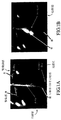
ある実施例では、図3に示されているように、5つの個別のトランスデューサ32−32が直線上に配置され、走査ヘッドの間は物理的に分離されている。この場合には、分離は5センチメートルである。ただし、これは変動が可能であるが。典型的には、この5走査ヘッド構成は、腹部領域をカバーして、大動脈の所望の部分の走査カバレッジを提供する。この実施例では、超音波信号は、同一の運動において、相互に干渉しないように並列的に発生される。複数の走査円錐の幾何学的構成は固定されているので、この実施例は、円錐間での最良の協調を与える。これは最速のシステムではあるが、同時に、最もハードウェア集約的であって高価である。結果的に得られたデータは、遠隔的な処理のためにインターネットによって送ることができる。 In one embodiment, as shown in FIG. 3, five individual transducers 32-32 are arranged in a straight line and are physically separated between the scan heads. In this case, the separation is 5 centimeters. However, this can vary. Typically, this five scan head configuration covers the abdominal region and provides scan coverage of the desired portion of the aorta. In this embodiment, ultrasonic signals are generated in parallel so as not to interfere with each other in the same motion. This embodiment provides the best coordination between the cones since the geometry of the scan cones is fixed. While this is the fastest system, it is also the most hardware intensive and expensive. The resulting data can be sent over the internet for remote processing.
しかし、トランスデューサのこれ以外の配列や数を用いることもできる。スキャナにおけるトランスデューサの幾何学的な移動は、システムの計算論的な要求を減少させるように構成することができる。例えば、個々のトランスデューサをシーケンシャルに付勢することにより、ただ1つの走査ヘッドからの情報だけを一度に処理するようにすることができる。そして、結果的に得られた情報を組み合わせて、腹部大動脈に関する総合的な走査情報を得ることができる。 However, other arrangements and numbers of transducers can be used. The geometric movement of the transducer in the scanner can be configured to reduce the computational requirements of the system. For example, the individual transducers can be energized sequentially to process only information from a single scan head at a time. Then, by combining information obtained as a result, comprehensive scanning information regarding the abdominal aorta can be obtained.
このような追加的な配列において、1つの超音波走査円錐を用いた複数走査を行うことができる。ユーザは、患者の腹部を下方向に向かう直線に沿って、装置をその都度再位置決めしながら、大動脈領域の単一円錐走査を複数回行う。すべての走査についてのデータは記憶され、遠隔処理のためにインターネットを介して送られる。 In such an additional arrangement, multiple scans using one ultrasonic scan cone can be performed. The user performs a single conical scan of the aortic region multiple times, repositioning the device each time along a straight line down the patient's abdomen. Data for all scans is stored and sent over the internet for remote processing.
更に別の実施例では、単一の走査円錐と単一の走査とを用いて、走査の後で、装置上に大動脈の直径が表示される。ユーザは、最大の直径を見つけるまで、装置を腹部全体を移動させる。この場合、直径は、完全な3次元走査円錐と単一の2次元パワー・ドップラ平面とのいずれかから計算される。 In yet another embodiment, a single scan cone and single scan are used to display the diameter of the aorta on the device after the scan. The user moves the device across the abdomen until the maximum diameter is found. In this case, the diameter is calculated from either a complete 3D scanning cone or a single 2D power Doppler plane.
単一の2次元パワー・ドップラ平面が用いられる場合には、直径情報はより速く与えられ、ユーザは、最大の大動脈直径を探し、最大値が決定されたらボタンを押下し、その結果、この装置は完全な3次元走査を行う。3次元走査では、より正確な最大直径を得ることができ、結果として得られる3次元イメージは後でのウェブ・サーバへのアップロードのために記憶される。しかし、このアプローチでは、ユーザは、2次元の平面が大動脈の真の断面を横断的に切断するように装置の向き付けをしなければならない。パワー・ドップラはこの同じ情報を含むため、ドップラ・オーディオ照準は用いられない。 If a single two-dimensional power Doppler plane is used, the diameter information is given faster and the user looks for the maximum aortic diameter and presses the button when the maximum is determined, so that the device Performs a complete three-dimensional scan. With 3D scanning, a more accurate maximum diameter can be obtained and the resulting 3D image is stored for later uploading to a web server. However, this approach requires the user to orient the device so that a two-dimensional plane cuts across the true cross section of the aorta. Since power Doppler contains this same information, Doppler audio aiming is not used.
3次元走査円錐の使用により、このような向き付けの必要性がなくなり、ユーザは、装置を任意の向きに配置することが可能になる。ユーザは、単に、患者の腹部を移動させながら、3次元のイメージ走査を複数行うことになる。完全な3次元のイメージングを行わないときには、この装置は、ドップラ・オーディオを出力して、ユーザによる装置の照準を導く。それぞれの走査の後で、その走査によってカバーされた大動脈の断面の直径が表示され、新たな走査からの直径がそれ以前の直径のいずれかよりも大きい場合には、イメージが記憶される。この実施例で得られるイメージは、パワー・ドップラ平面からのものであっても3次元走査円錐からのものであっても、遠隔的な更なる処理やレンダリングのためにインターネット経由で最適に送信することが可能である。 The use of a three-dimensional scanning cone eliminates the need for such orientation and allows the user to position the device in any orientation. The user simply performs a plurality of three-dimensional image scans while moving the patient's abdomen. When not performing full three-dimensional imaging, the device outputs Doppler audio to guide the device to the user. After each scan, the diameter of the cross section of the aorta covered by that scan is displayed, and if the diameter from the new scan is greater than any of the previous diameters, the image is stored. The image obtained in this embodiment, whether from a power Doppler plane or from a 3D scanning cone, is optimally transmitted over the Internet for further remote processing and rendering. It is possible.
次に、超音波情報は、図6のブロック図の一部に示されているように処理される。上の説明で1次元走査と称されていたものは、ブロック36に示されている。既に述べたように、これは、走査ヘッドが固定位置にある単一のビームである。トランスデューサは、単一の角度φでパルス化された超音波信号を送信し、帰ってきた信号を受信する。
The ultrasound information is then processed as shown in part of the block diagram of FIG. What was referred to as a one-dimensional scan in the above description is shown in
図4は、音を生じさせるドップラ処理システムを示している。血流からの帰還信号36は、トランスデューサ38を経由してTGCゲイン装置40に与えられる。TGCゲイン装置からの信号は、次に、42において直角対を用いて処理され、44において血流の速度が推定され、速度に対応するシヌソイド信号が発生器46において発生される。発生器46によって生じるシヌソイドは単調であるから、49において発生器48からのホワイトノイズがシヌソイド発生器46からの出力に加えられ、その結果得られる信号はマイクロコントローラ50に与えられ、マイクロコントローラ50からの出力はスピーカ52に与えられ、スピーカ52が可聴の血流音を生じる。
FIG. 4 shows a Doppler processing system that produces sound. The
再び図6を参照すると、ドップラ血流音(ブロック37)は、上述したようにオペレータによって用いられ、ブロック54に示されるように、スキャナは完全な3次元走査動作を開始するのに適するように位置決めされる。
Referring again to FIG. 6, the Doppler blood flow sound (block 37) is used by the operator as described above, as shown in
既に示したように、それぞれのトランスデューサによる3次元走査の結果は、図2A及び図2Bに示されているように、変数r(深度)とφ(走査平面角度)とθ(回転角度)とを含む平面座標での情報である。本発明によるシステムでは、大動脈の3次元での走査を得るために、平面座標で得られた情報は球座標に変換される。球座標に変換することによって、走査データは、大動脈に対してほぼ直角に配置された一連のデータ「スライス」で構成されることになる。これは、境界及び直径情報を正確に決定することを可能にするという点で望ましい。球座標でのこれらのデータの「スライス」は、レンジ又は深度r(平面座標の場合と類似する)と、特定のスライスの中でのビームの傾斜角度βと、垂直軸に対するスライス全体の傾斜角度ψと、回転角度γとを含む4つの変数で表現される。球座標における任意の点Prは、平面座標における任意の点Pから、以下の数式に従って計算することができる。 As already indicated, the results of the three-dimensional scanning with each transducer are the variables r (depth), φ (scanning plane angle) and θ (rotation angle), as shown in FIGS. 2A and 2B. It is information in plane coordinates including. In the system according to the invention, the information obtained in planar coordinates is converted into spherical coordinates in order to obtain a three-dimensional scan of the aorta. By converting to spherical coordinates, the scan data will consist of a series of data “slices” arranged approximately perpendicular to the aorta. This is desirable in that it allows the boundary and diameter information to be determined accurately. The “slice” of these data in spherical coordinates is the range or depth r (similar to that in planar coordinates), the tilt angle β of the beam within a particular slice, and the tilt angle of the entire slice relative to the vertical axis. It is expressed by four variables including ψ and the rotation angle γ. The arbitrary point Pr in the spherical coordinates can be calculated from the arbitrary point P in the plane coordinates according to the following formula.

境界検出プロセスは、図7に示されてる。このプロセスは、大動脈の断面は円か長円(オーバル)であるという事実に基づいて、楕円適合アプローチを用いる。断面スライス(ブロック64)を用い、垂直方向からの角度が0度である傾斜角ψを有するスライスから出発すると、そのスライスに対する大動脈の中心点は、正方形の「ウィンドウ」を移動させて、そのウィンドウの中のピクセル全部があるスレショルドよりも下であるかどうかを調べることによって、決定される。この中心点は、ブロック・ウィンドウ化のステップによって合格する点を平均化することによって決定される(ブロック66)。2次元のローパスフィルタが次に用いられ、不所望のノイズが除去される(ブロック68)。 The boundary detection process is shown in FIG. This process uses an ellipse fitting approach based on the fact that the cross section of the aorta is a circle or an oval. Using a cross-sectional slice (block 64) and starting from a slice with an angle of inclination ψ that is 0 degrees from the vertical direction, the center point of the aorta for that slice moves the square “window” and This is determined by checking if all the pixels in are below a certain threshold. This center point is determined by averaging the points that pass by the block windowing step (block 66). A two-dimensional low-pass filter is then used to remove unwanted noise (block 68).
第1のスライスの中心点から外向きに360度にわたって、ブロック70に示されている再サンプリングによっt、強度プロファイルが得られる。大動脈壁の内層すなわち表面は、中心点からレンジを増加させていったときに、その強度がこのプロファイルのスレショルドを超える最初の点である。ここで、楕円適合(ellipse fitting)が用いられて、ブロック72に示されているように、大動脈壁を画定する。適合された楕円のセントロイドが決定され(ブロック73)、そしてこの点は次のスライスに射影される(ブロック74)。次のスライスは、最初のスライスと同じ方法で処理されて、次のスライスの境界が決定される(ブロック75)。これが、トランスデューサ(走査ヘッド)からのすべてのスライスが処理されるまで継続される。
The intensity profile is obtained by resampling shown in
上で説明された自動境界検出システムは、連続的な超音波スライスにおいて動作する。この情報は、異なる視点から確認し訂正することができる。例えば、スライス座標における境界の点は平面座標に変換して表示することができる。平面イメージでは、境界を確認し修正することができ、平面座標におけるこれらの修正された点は、再処理及び制定のためにスライス座標にもう一度変換することができる。これは、図6のブロック77及び78に示されている。
The automatic boundary detection system described above operates on successive ultrasound slices. This information can be confirmed and corrected from different viewpoints. For example, boundary points in slice coordinates can be converted into plane coordinates and displayed. In a planar image, the boundaries can be identified and modified, and these modified points in planar coordinates can be converted back to slice coordinates for reprocessing and establishment. This is indicated by
(3次元走査からの)それぞれの3次元データ・セットの境界は、複数走査ヘッドの走査装置(DCD)によって得られる位置及び方位情報を用いてすべての境界を重畳させることによって、空間的に合成する、すなわち、相互に加算することができる。しかし、複数走査ヘッドのイメージの合成された境界は、大動脈に沿って相互に交差し重なり合う。それぞれの境界は、原点からの角度が均一に配分されている同数の点を含む。整頓されていない境界はソートされ、ローパスフィルタを用いて想定範囲外のものが除外される。次に、再サンプリングによる線形回帰を用いて、それぞれの境界における点を平面に適合させる。図8Aから図8Dは、重畳(8A)から、ソーティング(8B)、ローパスフィルタリング(8C)そして線形回帰を用いた再サンプリング(8D)までの境界合成ステップを結果を示している。図8Cのフィルタリングされた境界点は、単一の平面にはない。線形回帰を用いると、以下で詳述するように、図8Dの合成された境界は直径の測定及び表面のレンダリングが可能な状態になる。 The boundaries of each 3D data set (from a 3D scan) are spatially synthesized by superimposing all the boundaries using position and orientation information obtained by a multi-scan head scanning device (DCD). That is, they can be added to each other. However, the combined boundaries of the images of the multiple scan heads intersect and overlap each other along the aorta. Each boundary includes the same number of points that are uniformly distributed in angle from the origin. Unordered boundaries are sorted, and low-pass filters are used to exclude out of bounds. Next, a linear regression with resampling is used to fit the points at each boundary to the plane. 8A to 8D show the results of the boundary synthesis steps from superposition (8A), sorting (8B), low-pass filtering (8C), and resampling (8D) using linear regression. The filtered boundary points in FIG. 8C are not in a single plane. Using linear regression, the synthesized boundary of FIG. 8D is ready for diameter measurement and surface rendering, as described in detail below.
このシステムは、また、複数走査ヘッドのDCDの3次元走査情報から、ブロック79に示されているように、イメージ合成技術を用いる。これによると、イメージ・ウィンドウは、長軸方向の断面全体が正常な大動脈瘤と腸骨分岐部とを含むように、大動脈に沿って長軸方向に拡張される。複数の走査ヘッドを用いるイメージの合成が優れているのは、それぞれの走査ヘッドによって個別に生じる影のパターンを減少させ、ある1つのイメージでは存在しているが別のイメージには存在していないデータが合成されたイメージに現れることを可能にするからである。大動脈の長軸方向の視野の軸は、複数の境界の中心点の接続部であり、3次元データのそれぞれの頂点からこの軸を通過する走査線が収集される。1つの平面に存在しない走査線は、3次元データの5つの頂点を含む平面に射影され、画像化されて、大動脈の長軸方向の視野を形成する。図9は、合成のこの長軸方向の視野を示している。 The system also uses an image composition technique, as shown in block 79, from the three-dimensional scan information of the multi-scan head DCD. According to this, the image window is extended in the longitudinal direction along the aorta so that the entire longitudinal section includes a normal aneurysm and iliac bifurcation. The combination of images using multiple scan heads is superior because it reduces the shadow pattern produced by each scan head individually and is present in one image but not in another. This is because it allows data to appear in the synthesized image. The axis of the visual field in the major axis direction of the aorta is a connection portion between the center points of a plurality of boundaries, and a scanning line passing through this axis is collected from each vertex of three-dimensional data. Scan lines that do not exist in one plane are projected onto a plane containing five vertices of three-dimensional data and imaged to form the major field of view of the aorta. FIG. 9 shows this long axis view of the synthesis.
イメージ合成の結果は、以下で詳細に説明される表面レンダリングに用いられる。
このシステムは、また、ドップラ技術を用いた動脈中の血流解析も行うことができる(ブロック83)。大動脈壁の識別は重要であるが、大動脈の中の血流も重要である。示されている実施例では、同じ走査ヘッドから4つの連続的な超音波が送信され、その帰還信号が送信速度と同期して、つまり、送信周波数の4倍の速度でサンプリングされる。直交対であるI(同相)及びQ(直交相)は、サンプルから次の数式と図10に従って計算される。
The result of the image composition is used for surface rendering, which will be described in detail below.
The system can also perform blood flow analysis in the artery using Doppler technology (block 83). The identification of the aortic wall is important, but the blood flow in the aorta is also important. In the embodiment shown, four consecutive ultrasound waves are transmitted from the same scan head and the feedback signal is sampled synchronously with the transmission rate, i.e. at a rate four times the transmission frequency. The quadrature pair I (in-phase) and Q (quadrature) are calculated from the sample according to the following formula and FIG.
再び図6を、特にその表面レンダリングのステップを参照すると、大動脈の3次元イメージが、共に既に論じたイメージ合成情報(ブロック81)と複数の3次元合成情報(ブロック77)とから作成される。この表面レンダリング画像化(ブロック88)は、様々な周知の方法を用いて達成することができる。この表面情報は、動脈瘤の位置及びその広がり(ブロック89)と、結果的なステントの設計(ブロック90)とを決定する際に役に立つ。 Referring again to FIG. 6, and in particular to its surface rendering step, a three-dimensional image of the aorta is created from the image composition information (block 81) and a plurality of three-dimensional composition information (block 77) already discussed together. This surface rendering imaging (block 88) can be accomplished using a variety of well-known methods. This surface information is useful in determining the location of the aneurysm and its extent (block 89) and the resulting stent design (block 90).
腹部大動脈瘤の直径の測定(ブロック92)は、複数の3次元合成情報(ブロック77)から得られる。腹部大動脈の直径は、動脈瘤を検出しモニタすることを可能にする。直径の測定に関しては現時点では一般的に受け入れられている方法は存在しないが、多くの医師は、大動脈を横断する方向の断面を直径として用いている。また、直径は、大動脈の中心線の平均の長さを用い、それを360度にわたって大動脈の境界まで拡張することによって決定することもできる。 The measurement of the diameter of the abdominal aortic aneurysm (block 92) is obtained from a plurality of three-dimensional composite information (block 77). The diameter of the abdominal aorta allows an aneurysm to be detected and monitored. Although there is currently no generally accepted method for measuring diameter, many physicians use a cross section in the direction across the aorta as the diameter. The diameter can also be determined by taking the average length of the centerline of the aorta and extending it to the aortic boundary over 360 degrees.
直径(D)は、面積又は円周の計算値を用いて、次の数式を用いて計算することができる。次の数式で、「area」とは面積、「circumference」とは円周である。 The diameter (D) can be calculated using the following formula using the calculated value of the area or circumference. In the following formula, “area” is an area, and “circumference” is a circumference.
最大の断面積の測定値は、センチメートル単位で、直径と共に表示されるのが通常である。この装置は、大動脈の中心線と超音波ビームの中心線とに対するイメージの角度を知っているので、超音波の3次元的な広がりに対する訂正が可能であり、結果的に、次で説明するように、軸から独立(off-axis)な正確な直径の測定値が得られる。 The maximum cross-sectional area measurement is usually displayed with the diameter in centimeters. Since this device knows the angle of the image with respect to the centerline of the aorta and the centerline of the ultrasound beam, it can correct for the three-dimensional spread of the ultrasound and, as a result, will be described below. In addition, accurate diameter measurements are obtained that are off-axis.
超音波データのスライスを用いて断面の直径を決定する基本的な手順のステップは、最初に、既に論じたように、それぞれのスライスの中心の決定を含む。次に、長軸上の同じ間隔での中心又はセントロイド点が、再サンプリングされる。それぞれの平面における中心点に対して任意の平面を傾斜させ、それぞれの平面上の境界点が再サンプリングされ、傾斜角方向の直径が推定される。次に、最小の直径を有する傾斜角が選択され、その傾斜角における直径が計算される。そして、(大動脈の長さにわたる)拡大された直径測定値が、所望の距離にわたって直径をプロットすることによって示される。この直径の測定値は、大動脈瘤(AAA)の判断(ブロック94)に加え、そのサイズ(ブロック95)と、その動脈瘤が成長したかどうか(モニタリング機能)(ブロック96)との判断に用いられる。ブロック94から診断を行うことができ(ブロック98)、手術が示唆されるかどうかはブロック95及び96から決定される(ブロック100)。
The basic procedural steps for determining the diameter of a cross-section using slices of ultrasound data initially involve determining the center of each slice, as already discussed. Next, the center or centroid points at the same interval on the long axis are resampled. An arbitrary plane is tilted with respect to the center point in each plane, the boundary points on each plane are resampled, and the diameter in the tilt angle direction is estimated. Next, the tilt angle with the smallest diameter is selected and the diameter at that tilt angle is calculated. The expanded diameter measurement (over the length of the aorta) is then shown by plotting the diameter over the desired distance. This diameter measurement is used to determine the size of the aortic aneurysm (AAA) (block 94) and its size (block 95) and whether the aneurysm has grown (monitoring function) (block 96). It is done. A diagnosis can be made from block 94 (block 98) and whether an operation is suggested is determined from
ドップラ・フロー画像化プロセス(ブロック86)からの情報は、既存のステントが漏れているかどうか(ブロック102)、そして、ステントの修理が必要かどうか(ブロック104)を判断するのに用いることができる。ブロック90、98、100及び104においてなされた決定及び勧告は、提供されている医学的な出力情報を検討する医師によってなされる。このシステム自体は、出力情報と予め設定されたスレショルド値との比較に基づいて、勧告のために用いられる。
Information from the Doppler flow imaging process (block 86) can be used to determine whether an existing stent is leaking (block 102) and whether a stent needs repair (block 104). . The decisions and recommendations made in
従って、本発明では、腹部大動脈瘤を判断しモニタするシステムが開示され、超音波走査とその情報の処理により、選択された大動脈の長さにわたる大動脈の境界及び直径情報を得ることができ、結果的に、動脈瘤の有無の判断することができ、また、動脈瘤が存在する場合には以前の走査の時からの変化を判断することができる。本発明のこれ以外の特徴としては、血流に関するドップラ解析を用いて、先に配置されているステントが漏れているかどうかを判断することができる。 Accordingly, in the present invention, a system for determining and monitoring an abdominal aortic aneurysm is disclosed, and ultrasound scanning and processing of that information can provide aortic boundary and diameter information over the length of the selected aorta, resulting in a result. In particular, the presence or absence of an aneurysm can be determined, and if an aneurysm is present, a change from the previous scan can be determined. As another feature of the present invention, it is possible to determine whether or not a previously placed stent is leaking using Doppler analysis relating to blood flow.
また、大動脈の表面レンダリングにより、大動脈に沿った動脈瘤の位置とステントの設計とを判断するのに役立つ。この表面レンダリングは、重要である。というのは、これにより、医師が治療の選択肢を議論し、医学的な状態の範囲と意義について患者が視覚的に理解することを容易にするからである。 Aortic surface rendering also helps determine the location of the aneurysm along the aorta and the stent design. This surface rendering is important. This is because it makes it easier for physicians to discuss treatment options and to help patients visually understand the scope and significance of medical conditions.
また、ウェブ・サーバがデータベースを組み入れているため、患者の大動脈の状態に関する記録を時間経過にわたって維持管理することが可能である。状態の進行を正確にモニタすることができるし、それによって、よりよい治療上の決定が可能になる。表面レンダリング情報を用いると、この疾病の進行を時間経過にわたって、その臓器の時間経過にわたるビデオ映像のように視覚的に観察することができる。 Also, because the web server incorporates a database, it is possible to maintain records regarding the condition of the patient's aorta over time. The progress of the condition can be accurately monitored, thereby allowing better therapeutic decisions. With surface rendering information, the progression of the disease can be visually observed over time, like a video image over the time course of the organ.
以上では、本発明の好適実施例を、例示のために開示したが、冒頭の特許請求の範囲の記載によって定義される本発明の技術思想から離れることなく、この実施例に対して、様々な変更、修正、代替を行うことが可能である。 In the above, preferred embodiments of the present invention have been disclosed for the purpose of illustration, but various modifications may be made to this embodiment without departing from the spirit of the invention as defined by the following claims. Changes, corrections and substitutions can be made.
Claims (19)
腹部大動脈の選択された部分の3次元超音波走査情報を、複数の走査線平面の形式で取得するデータ収集手段と、
前記走査線平面情報を、変換された走査線平面が前記大動脈をほぼ垂直に通過するようにスライスする座標に変換するプロセッサと、
前記変換された操作情報から大動脈境界情報を決定するプロセッサと、
前記境界情報から前記大動脈の直径を計算する計算回路と、
を備えており、前記大動脈に沿った複数の位置での前記大動脈の直径情報は、腹部大動脈における動脈瘤の存在を判断する際に有用であることを特徴とするシステム。 A system for evaluating and monitoring an abdominal aortic aneurysm,
Data acquisition means for acquiring three-dimensional ultrasound scanning information of a selected portion of the abdominal aorta in the form of a plurality of scanning line planes;
A processor that converts the scan line plane information into coordinates that slice the converted scan line plane to pass substantially perpendicularly through the aorta;
A processor for determining aortic boundary information from the converted operation information;
A calculation circuit for calculating the diameter of the aorta from the boundary information;
And the diameter information of the aorta at a plurality of positions along the aorta is useful in determining the presence of an aneurysm in the abdominal aorta.
腹部大動脈の選択された部分の3次元超音波情報を取得し、前記超音波情報を処理して大動脈境界情報を決定する手段と、
前記境界情報を合成して、表面レンダリングされて前記大動脈の現実的な表現を生じる前記大動脈の視覚的表現を生じるプロセッサと、
を備えていることを特徴とするシステム。 A system for monitoring an abdominal aortic aneurysm,
Means for obtaining three-dimensional ultrasound information of a selected portion of the abdominal aorta and processing the ultrasound information to determine aortic boundary information;
A processor that synthesizes the boundary information to produce a visual representation of the aorta that is surface rendered to produce a realistic representation of the aorta;
A system characterized by comprising:
腹部大動脈の選択された部分の3次元超音波走査情報を、複数の走査線平面の形式で取得するステップと、
前記走査線平面情報を、変換された走査線平面が前記大動脈をほぼ垂直に通過するようにスライスする座標に変換するステップと、
前記変換された操作情報から大動脈境界情報を決定するステップと、
前記境界情報から前記大動脈の直径を計算するステップと、
を含み、前記大動脈に沿った複数の位置での前記大動脈の直径情報は、腹部大動脈における動脈瘤の存在を判断する際に有用であることを特徴とする方法。 A method for evaluating and monitoring an abdominal aortic aneurysm,
Obtaining three-dimensional ultrasound scan information of a selected portion of the abdominal aorta in the form of a plurality of scan line planes;
Converting the scan line plane information into coordinates that slice the converted scan line plane to pass substantially perpendicularly through the aorta;
Determining aortic boundary information from the converted operation information;
Calculating the diameter of the aorta from the boundary information;
And the diameter information of the aorta at a plurality of positions along the aorta is useful in determining the presence of an aneurysm in the abdominal aorta.
Applications Claiming Priority (2)
| Application Number | Priority Date | Filing Date | Title |
|---|---|---|---|
| US10/246,945 US6905468B2 (en) | 2002-09-18 | 2002-09-18 | Three-dimensional system for abdominal aortic aneurysm evaluation |
| PCT/US2003/030182 WO2004026119A2 (en) | 2002-09-18 | 2003-09-17 | Three-dimensional system for abdominal aortic aneurysm evaluation |
Related Child Applications (1)
| Application Number | Title | Priority Date | Filing Date |
|---|---|---|---|
| JP2010263788A Division JP5466139B2 (en) | 2002-09-18 | 2010-11-26 | 3D system for evaluating abdominal aortic aneurysms |
Publications (2)
| Publication Number | Publication Date |
|---|---|
| JP2005538811A true JP2005538811A (en) | 2005-12-22 |
| JP2005538811A5 JP2005538811A5 (en) | 2010-06-17 |
Family
ID=31992400
Family Applications (2)
| Application Number | Title | Priority Date | Filing Date |
|---|---|---|---|
| JP2004538489A Withdrawn JP2005538811A (en) | 2002-09-18 | 2003-09-17 | 3D system for evaluating abdominal aortic aneurysms |
| JP2010263788A Expired - Lifetime JP5466139B2 (en) | 2002-09-18 | 2010-11-26 | 3D system for evaluating abdominal aortic aneurysms |
Family Applications After (1)
| Application Number | Title | Priority Date | Filing Date |
|---|---|---|---|
| JP2010263788A Expired - Lifetime JP5466139B2 (en) | 2002-09-18 | 2010-11-26 | 3D system for evaluating abdominal aortic aneurysms |
Country Status (6)
| Country | Link |
|---|---|
| US (1) | US6905468B2 (en) |
| EP (1) | EP1545286B1 (en) |
| JP (2) | JP2005538811A (en) |
| AU (1) | AU2003270885A1 (en) |
| CA (1) | CA2499174A1 (en) |
| WO (1) | WO2004026119A2 (en) |
Cited By (3)
| Publication number | Priority date | Publication date | Assignee | Title |
|---|---|---|---|---|
| JP2010207531A (en) * | 2009-03-12 | 2010-09-24 | Toshiba Corp | Mri apparatus and data processor |
| JP2010227603A (en) * | 2010-06-16 | 2010-10-14 | Aloka Co Ltd | Ultrasonic diagnostic apparatus |
| JP2017506930A (en) * | 2014-01-10 | 2017-03-16 | ボルケーノ コーポレイション | Detection of endoleak associated with aneurysm repair |
Families Citing this family (34)
| Publication number | Priority date | Publication date | Assignee | Title |
|---|---|---|---|---|
| US20090062644A1 (en) * | 2002-06-07 | 2009-03-05 | Mcmorrow Gerald | System and method for ultrasound harmonic imaging |
| US20040127797A1 (en) * | 2002-06-07 | 2004-07-01 | Bill Barnard | System and method for measuring bladder wall thickness and presenting a bladder virtual image |
| US20060025689A1 (en) * | 2002-06-07 | 2006-02-02 | Vikram Chalana | System and method to measure cardiac ejection fraction |
| US8221321B2 (en) | 2002-06-07 | 2012-07-17 | Verathon Inc. | Systems and methods for quantification and classification of fluids in human cavities in ultrasound images |
| GB2391625A (en) | 2002-08-09 | 2004-02-11 | Diagnostic Ultrasound Europ B | Instantaneous ultrasonic echo measurement of bladder urine volume with a limited number of ultrasound beams |
| US20090112089A1 (en) * | 2007-10-27 | 2009-04-30 | Bill Barnard | System and method for measuring bladder wall thickness and presenting a bladder virtual image |
| US20100036252A1 (en) * | 2002-06-07 | 2010-02-11 | Vikram Chalana | Ultrasound system and method for measuring bladder wall thickness and mass |
| US7520857B2 (en) * | 2002-06-07 | 2009-04-21 | Verathon Inc. | 3D ultrasound-based instrument for non-invasive measurement of amniotic fluid volume |
| US7819806B2 (en) * | 2002-06-07 | 2010-10-26 | Verathon Inc. | System and method to identify and measure organ wall boundaries |
| US8221322B2 (en) * | 2002-06-07 | 2012-07-17 | Verathon Inc. | Systems and methods to improve clarity in ultrasound images |
| US20080262356A1 (en) * | 2002-06-07 | 2008-10-23 | Vikram Chalana | Systems and methods for ultrasound imaging using an inertial reference unit |
| US20040249281A1 (en) * | 2003-06-09 | 2004-12-09 | Bjorn Olstad | Method and apparatus for extracting wall function information relative to ultrasound-located landmarks |
| US20050049495A1 (en) * | 2003-09-03 | 2005-03-03 | Siemens Medical Solutions Usa, Inc. | Remote assistance for medical diagnostic ultrasound |
| DE102004044435A1 (en) * | 2004-09-14 | 2006-03-30 | Siemens Ag | Method and device for diagnosis and therapy of the aortic aneurysm |
| US20060078196A1 (en) * | 2004-10-13 | 2006-04-13 | Siemens Medical Solutions Usa, Inc. | Distributed apexes for 3-D ultrasound scan geometry |
| CN100581465C (en) * | 2004-12-17 | 2010-01-20 | 皇家飞利浦电子股份有限公司 | System and method for predicting physical properties of an aneurysm from a three-dimensional model thereof |
| EP1922029B1 (en) * | 2005-08-18 | 2014-11-19 | Cook Medical Technologies LLC | Assembly of stent grafts |
| US20090131791A1 (en) * | 2005-08-22 | 2009-05-21 | Koninklijke Philips Electronics N.V. | Ultrasonic Diagnostic Imaging System With Spectral and Audio Tissue Doppler |
| US7672496B2 (en) * | 2006-06-21 | 2010-03-02 | Icad, Inc. | Forming three dimensional objects using a decision rule in medical image data |
| US8167803B2 (en) * | 2007-05-16 | 2012-05-01 | Verathon Inc. | System and method for bladder detection using harmonic imaging |
| US8133181B2 (en) * | 2007-05-16 | 2012-03-13 | Verathon Inc. | Device, system and method to measure abdominal aortic aneurysm diameter |
| JP5214920B2 (en) * | 2007-07-24 | 2013-06-19 | 株式会社東芝 | Ultrasonic diagnostic apparatus and acoustic output method of ultrasonic diagnostic apparatus |
| US8225998B2 (en) * | 2008-07-11 | 2012-07-24 | Es&S Innovations Llc | Secure ballot box |
| US20110052026A1 (en) * | 2009-08-28 | 2011-03-03 | Siemens Corporation | Method and Apparatus for Determining Angulation of C-Arm Image Acquisition System for Aortic Valve Implantation |
| US8712122B2 (en) | 2011-03-31 | 2014-04-29 | International Business Machines Corporation | Shape based similarity of continuous wave doppler images |
| US8728148B2 (en) | 2011-11-09 | 2014-05-20 | Cook Medical Technologies Llc | Diameter reducing tie arrangement for endoluminal prosthesis |
| EP3435382A1 (en) | 2017-07-27 | 2019-01-30 | Koninklijke Philips N.V. | Imaging method, controller and imaging system, for monitoring a patient post evar |
| RU2689769C1 (en) * | 2018-01-31 | 2019-05-28 | Государственное Бюджетное Учреждение "Санкт-Петербургский Научно-Исследовательский Институт Скорой Помощи Им. И.И. Джанелидзе" | Method for measuring length of proximal cervical abdominal aortic aneurysm |
| CN111885960B (en) * | 2018-03-13 | 2023-10-13 | 韦拉索恩股份有限公司 | Universal interlacing of ultrasound probes |
| US11127138B2 (en) | 2018-11-20 | 2021-09-21 | Siemens Healthcare Gmbh | Automatic detection and quantification of the aorta from medical images |
| CA3126020A1 (en) * | 2019-01-17 | 2020-07-23 | Verathon Inc. | Systems and methods for quantitative abdominal aortic aneurysm analysis using 3d ultrasound imaging |
| US11911220B2 (en) | 2019-10-17 | 2024-02-27 | Verathon Inc. | Systems and methods for ultrasound scanning |
| CN114224484B (en) * | 2021-12-13 | 2023-05-30 | 杭州脉流科技有限公司 | Surface area localization method, device, computer equipment and storage medium for intracranial aneurysm |
| US11538163B1 (en) * | 2022-01-06 | 2022-12-27 | Rowan University | Training a neural network for a predictive aortic aneurysm detection system |
Citations (6)
| Publication number | Priority date | Publication date | Assignee | Title |
|---|---|---|---|---|
| JPH03277351A (en) * | 1990-03-28 | 1991-12-09 | Toshiba Corp | Ultrasonic diagnostic device |
| JPH05285125A (en) * | 1991-07-03 | 1993-11-02 | Philips Gloeilampenfab:Nv | Method and device for extracting contour in studying multi-sliced and multi-phased heart mri by transmitting seed contour between images |
| US5825908A (en) * | 1995-12-29 | 1998-10-20 | Medical Media Systems | Anatomical visualization and measurement system |
| JP2000325348A (en) * | 1999-05-25 | 2000-11-28 | Ge Yokogawa Medical Systems Ltd | Method of producing three-dimensional image and ultrasonic diagnostic apparatus |
| WO2001037219A1 (en) * | 1999-11-19 | 2001-05-25 | General Electric Company | Method and apparatus for reformatting tubular volumetric bodies |
| WO2002007586A2 (en) * | 2000-07-21 | 2002-01-31 | Diagnostic Ultrasound Corporation | System for remote programming of ultrasound devices |
Family Cites Families (16)
| Publication number | Priority date | Publication date | Assignee | Title |
|---|---|---|---|---|
| US5159931A (en) * | 1988-11-25 | 1992-11-03 | Riccardo Pini | Apparatus for obtaining a three-dimensional reconstruction of anatomic structures through the acquisition of echographic images |
| US5125410A (en) * | 1989-10-13 | 1992-06-30 | Olympus Optical Co., Ltd. | Integrated ultrasonic diagnosis device utilizing intra-blood-vessel probe |
| US5360005A (en) * | 1992-01-10 | 1994-11-01 | Wilk Peter J | Medical diagnosis device for sensing cardiac activity and blood flow |
| US5972023A (en) * | 1994-08-15 | 1999-10-26 | Eva Corporation | Implantation device for an aortic graft method of treating aortic aneurysm |
| US5487388A (en) * | 1994-11-01 | 1996-01-30 | Interspec. Inc. | Three dimensional ultrasonic scanning devices and techniques |
| US6151404A (en) * | 1995-06-01 | 2000-11-21 | Medical Media Systems | Anatomical visualization system |
| US7194117B2 (en) * | 1999-06-29 | 2007-03-20 | The Research Foundation Of State University Of New York | System and method for performing a three-dimensional virtual examination of objects, such as internal organs |
| US5871019A (en) * | 1996-09-23 | 1999-02-16 | Mayo Foundation For Medical Education And Research | Fast cardiac boundary imaging |
| US6148095A (en) * | 1997-09-08 | 2000-11-14 | University Of Iowa Research Foundation | Apparatus and method for determining three-dimensional representations of tortuous vessels |
| US6511325B1 (en) * | 1998-05-04 | 2003-01-28 | Advanced Research & Technology Institute | Aortic stent-graft calibration and training model |
| US6346124B1 (en) * | 1998-08-25 | 2002-02-12 | University Of Florida | Autonomous boundary detection system for echocardiographic images |
| US6524249B2 (en) * | 1998-11-11 | 2003-02-25 | Spentech, Inc. | Doppler ultrasound method and apparatus for monitoring blood flow and detecting emboli |
| US6196972B1 (en) * | 1998-11-11 | 2001-03-06 | Spentech, Inc. | Doppler ultrasound method and apparatus for monitoring blood flow |
| JP4768100B2 (en) * | 2000-04-25 | 2011-09-07 | 日立アロカメディカル株式会社 | Ultrasonic diagnostic equipment |
| US6643533B2 (en) * | 2000-11-28 | 2003-11-04 | Ge Medical Systems Global Technology Company, Llc | Method and apparatus for displaying images of tubular structures |
| US20040068180A1 (en) * | 2002-10-04 | 2004-04-08 | Jeffrey Collins | Rotary ultrasound scanner for soft tissue examination |
-
2002
- 2002-09-18 US US10/246,945 patent/US6905468B2/en not_active Expired - Lifetime
-
2003
- 2003-09-17 CA CA002499174A patent/CA2499174A1/en not_active Abandoned
- 2003-09-17 EP EP03752599A patent/EP1545286B1/en not_active Expired - Lifetime
- 2003-09-17 WO PCT/US2003/030182 patent/WO2004026119A2/en active Application Filing
- 2003-09-17 JP JP2004538489A patent/JP2005538811A/en not_active Withdrawn
- 2003-09-17 AU AU2003270885A patent/AU2003270885A1/en not_active Abandoned
-
2010
- 2010-11-26 JP JP2010263788A patent/JP5466139B2/en not_active Expired - Lifetime
Patent Citations (6)
| Publication number | Priority date | Publication date | Assignee | Title |
|---|---|---|---|---|
| JPH03277351A (en) * | 1990-03-28 | 1991-12-09 | Toshiba Corp | Ultrasonic diagnostic device |
| JPH05285125A (en) * | 1991-07-03 | 1993-11-02 | Philips Gloeilampenfab:Nv | Method and device for extracting contour in studying multi-sliced and multi-phased heart mri by transmitting seed contour between images |
| US5825908A (en) * | 1995-12-29 | 1998-10-20 | Medical Media Systems | Anatomical visualization and measurement system |
| JP2000325348A (en) * | 1999-05-25 | 2000-11-28 | Ge Yokogawa Medical Systems Ltd | Method of producing three-dimensional image and ultrasonic diagnostic apparatus |
| WO2001037219A1 (en) * | 1999-11-19 | 2001-05-25 | General Electric Company | Method and apparatus for reformatting tubular volumetric bodies |
| WO2002007586A2 (en) * | 2000-07-21 | 2002-01-31 | Diagnostic Ultrasound Corporation | System for remote programming of ultrasound devices |
Cited By (3)
| Publication number | Priority date | Publication date | Assignee | Title |
|---|---|---|---|---|
| JP2010207531A (en) * | 2009-03-12 | 2010-09-24 | Toshiba Corp | Mri apparatus and data processor |
| JP2010227603A (en) * | 2010-06-16 | 2010-10-14 | Aloka Co Ltd | Ultrasonic diagnostic apparatus |
| JP2017506930A (en) * | 2014-01-10 | 2017-03-16 | ボルケーノ コーポレイション | Detection of endoleak associated with aneurysm repair |
Also Published As
| Publication number | Publication date |
|---|---|
| CA2499174A1 (en) | 2004-04-01 |
| EP1545286A4 (en) | 2009-04-01 |
| EP1545286B1 (en) | 2012-08-29 |
| JP2011056291A (en) | 2011-03-24 |
| WO2004026119A2 (en) | 2004-04-01 |
| US20040054280A1 (en) | 2004-03-18 |
| AU2003270885A8 (en) | 2004-04-08 |
| US6905468B2 (en) | 2005-06-14 |
| JP5466139B2 (en) | 2014-04-09 |
| EP1545286A2 (en) | 2005-06-29 |
| AU2003270885A1 (en) | 2004-04-08 |
| WO2004026119A3 (en) | 2004-05-27 |
Similar Documents
| Publication | Publication Date | Title |
|---|---|---|
| JP5466139B2 (en) | 3D system for evaluating abdominal aortic aneurysms | |
| JP6266160B2 (en) | Ultrasound system and method for identifying blood vessels | |
| JP5284123B2 (en) | Ultrasonic diagnostic apparatus and position information acquisition program | |
| JP4068234B2 (en) | Ultrasonic diagnostic equipment | |
| JP5658151B2 (en) | Apparatus, system and method for measuring the diameter of an abdominal aortic aneurysm | |
| US20140303499A1 (en) | Ultrasound diagnostic apparatus and method for controlling the same | |
| EP3554380B1 (en) | Target probe placement for lung ultrasound | |
| JP2005538811A5 (en) | ||
| JP2009089736A (en) | Ultrasonograph | |
| JP2008515520A (en) | Method and system for maintaining a consistent anatomical view of displayed image data | |
| JP4468432B2 (en) | Ultrasonic diagnostic equipment | |
| US20230181148A1 (en) | Vascular system visualization | |
| JP2011177495A (en) | Ultrasonic diagnostic apparatus and medical image processing apparatus | |
| KR20160064442A (en) | Medical image processing apparatus and medical image registration method using the same | |
| CA3154396A1 (en) | Systems and methods for ultrasound scanning | |
| JP2008099931A (en) | Medical image diagnostic device, medical image display device, and program | |
| JP2007222533A (en) | Ultrasonic diagnostic apparatus and ultrasonic image processing method | |
| JP2939434B2 (en) | Ultrasound diagnostic equipment | |
| JP2022074392A (en) | Ultrasonic diagnostic device, control method of ultrasonic diagnostic device, and control program of ultrasonic diagnostic device | |
| JP2006000456A (en) | Ultrasonic diagnostic apparatus | |
| US20190192111A1 (en) | Ultrasonic Imaging Device and Operation Method Thereof | |
| JP2006167080A (en) | Ultrasonic diagnostic apparatus | |
| EP3655972B1 (en) | Imaging method, controller and imaging system, for monitoring a patient post evar | |
| JP2001506517A (en) | Measurement of stenosis in coronary arteries | |
| JP2013052131A (en) | Ultrasonic diagnostic system and vasoconstriction improvement display program |
Legal Events
| Date | Code | Title | Description |
|---|---|---|---|
| A621 | Written request for application examination |
Free format text: JAPANESE INTERMEDIATE CODE: A621 Effective date: 20060915 |
|
| A977 | Report on retrieval |
Free format text: JAPANESE INTERMEDIATE CODE: A971007 Effective date: 20091021 |
|
| A131 | Notification of reasons for refusal |
Free format text: JAPANESE INTERMEDIATE CODE: A131 Effective date: 20091023 |
|
| A601 | Written request for extension of time |
Free format text: JAPANESE INTERMEDIATE CODE: A601 Effective date: 20100122 |
|
| A602 | Written permission of extension of time |
Free format text: JAPANESE INTERMEDIATE CODE: A602 Effective date: 20100129 |
|
| A524 | Written submission of copy of amendment under article 19 pct |
Free format text: JAPANESE INTERMEDIATE CODE: A524 Effective date: 20100423 |
|
| A02 | Decision of refusal |
Free format text: JAPANESE INTERMEDIATE CODE: A02 Effective date: 20100728 |
|
| A521 | Request for written amendment filed |
Free format text: JAPANESE INTERMEDIATE CODE: A523 Effective date: 20101126 |
|
| A911 | Transfer to examiner for re-examination before appeal (zenchi) |
Free format text: JAPANESE INTERMEDIATE CODE: A911 Effective date: 20110124 |
|
| A912 | Re-examination (zenchi) completed and case transferred to appeal board |
Free format text: JAPANESE INTERMEDIATE CODE: A912 Effective date: 20110624 |
|
| A761 | Written withdrawal of application |
Free format text: JAPANESE INTERMEDIATE CODE: A761 Effective date: 20111003 |