JP2005537368A - Sludge and charcoal conversion - Google Patents
Sludge and charcoal conversion Download PDFInfo
- Publication number
- JP2005537368A JP2005537368A JP2004533047A JP2004533047A JP2005537368A JP 2005537368 A JP2005537368 A JP 2005537368A JP 2004533047 A JP2004533047 A JP 2004533047A JP 2004533047 A JP2004533047 A JP 2004533047A JP 2005537368 A JP2005537368 A JP 2005537368A
- Authority
- JP
- Japan
- Prior art keywords
- reactor
- sludge
- carbide
- paddles
- conveyor
- Prior art date
- Legal status (The legal status is an assumption and is not a legal conclusion. Google has not performed a legal analysis and makes no representation as to the accuracy of the status listed.)
- Pending
Links
Images


Classifications
-
- C—CHEMISTRY; METALLURGY
- C10—PETROLEUM, GAS OR COKE INDUSTRIES; TECHNICAL GASES CONTAINING CARBON MONOXIDE; FUELS; LUBRICANTS; PEAT
- C10B—DESTRUCTIVE DISTILLATION OF CARBONACEOUS MATERIALS FOR PRODUCTION OF GAS, COKE, TAR, OR SIMILAR MATERIALS
- C10B47/00—Destructive distillation of solid carbonaceous materials with indirect heating, e.g. by external combustion
- C10B47/28—Other processes
- C10B47/32—Other processes in ovens with mechanical conveying means
-
- C—CHEMISTRY; METALLURGY
- C10—PETROLEUM, GAS OR COKE INDUSTRIES; TECHNICAL GASES CONTAINING CARBON MONOXIDE; FUELS; LUBRICANTS; PEAT
- C10B—DESTRUCTIVE DISTILLATION OF CARBONACEOUS MATERIALS FOR PRODUCTION OF GAS, COKE, TAR, OR SIMILAR MATERIALS
- C10B53/00—Destructive distillation, specially adapted for particular solid raw materials or solid raw materials in special form
- C10B53/02—Destructive distillation, specially adapted for particular solid raw materials or solid raw materials in special form of cellulose-containing material
-
- C—CHEMISTRY; METALLURGY
- C10—PETROLEUM, GAS OR COKE INDUSTRIES; TECHNICAL GASES CONTAINING CARBON MONOXIDE; FUELS; LUBRICANTS; PEAT
- C10G—CRACKING HYDROCARBON OILS; PRODUCTION OF LIQUID HYDROCARBON MIXTURES, e.g. BY DESTRUCTIVE HYDROGENATION, OLIGOMERISATION, POLYMERISATION; RECOVERY OF HYDROCARBON OILS FROM OIL-SHALE, OIL-SAND, OR GASES; REFINING MIXTURES MAINLY CONSISTING OF HYDROCARBONS; REFORMING OF NAPHTHA; MINERAL WAXES
- C10G1/00—Production of liquid hydrocarbon mixtures from oil-shale, oil-sand, or non-melting solid carbonaceous or similar materials, e.g. wood, coal
- C10G1/02—Production of liquid hydrocarbon mixtures from oil-shale, oil-sand, or non-melting solid carbonaceous or similar materials, e.g. wood, coal by distillation
-
- C—CHEMISTRY; METALLURGY
- C02—TREATMENT OF WATER, WASTE WATER, SEWAGE, OR SLUDGE
- C02F—TREATMENT OF WATER, WASTE WATER, SEWAGE, OR SLUDGE
- C02F11/00—Treatment of sludge; Devices therefor
- C02F11/10—Treatment of sludge; Devices therefor by pyrolysis
-
- Y—GENERAL TAGGING OF NEW TECHNOLOGICAL DEVELOPMENTS; GENERAL TAGGING OF CROSS-SECTIONAL TECHNOLOGIES SPANNING OVER SEVERAL SECTIONS OF THE IPC; TECHNICAL SUBJECTS COVERED BY FORMER USPC CROSS-REFERENCE ART COLLECTIONS [XRACs] AND DIGESTS
- Y02—TECHNOLOGIES OR APPLICATIONS FOR MITIGATION OR ADAPTATION AGAINST CLIMATE CHANGE
- Y02E—REDUCTION OF GREENHOUSE GAS [GHG] EMISSIONS, RELATED TO ENERGY GENERATION, TRANSMISSION OR DISTRIBUTION
- Y02E50/00—Technologies for the production of fuel of non-fossil origin
- Y02E50/10—Biofuels, e.g. bio-diesel
Abstract
汚泥および炭質の変換のための方法であって、
(a)油生成蒸気の気化のために、酸素の非存在下でリアクターの加熱ゾーンで変換される物質を加熱し、それにより蒸気生成物および固体残留物または炭化物の両方を生成するステップと、
(b)気相触媒反応を促進するために、リアクターの反応ゾーンで、決定された毎時重量空間速度(「WHSV」)にて蒸気生成物および炭化物を接触させるステップと、
(c)ガス状生成物および炭化物をリアクターから除去および分離するステップと、
を特徴とする方法。
上の方法による汚泥および炭質の変換のための装置についても述べる。A method for the conversion of sludge and charcoal,
(A) heating the material to be converted in the heating zone of the reactor in the absence of oxygen for the vaporization of oil-generating steam, thereby producing both a steam product and a solid residue or carbide;
(B) contacting the vapor product and carbide at a determined hourly weight space velocity (“WHSV”) in the reaction zone of the reactor to facilitate the gas phase catalytic reaction;
(C) removing and separating gaseous products and carbides from the reactor;
A method characterized by.
An apparatus for the conversion of sludge and charcoal by the above method is also described.
Description
本発明は汚泥および炭質の変換に関する。本発明はさらに詳細には、下水、工業汚泥および他の炭質中の有機成分の変換からの改良油生成物の製造のための方法および装置に関する。 The present invention relates to sludge and charcoal conversion. The present invention more particularly relates to a method and apparatus for the production of improved oil products from the conversion of organic components in sewage, industrial sludge and other carbonaceous materials.
汚泥は、下水および他の工業廃水の処理で避けられない副生成物である。従来、そのような汚泥の廃棄は費用がかかり、廃水処理の年間総費用の半分を構成する。歴史的に主な汚泥廃棄の選択肢は、農業利用、埋立ておよび焼却を含んでいる。また歴史的に、廃水処理プラントは、汚泥生成を最小限にするよう設計されており、大半の労力は、廃棄または利用の前に汚泥の量を安定化および削減することに費やされる。 Sludge is an inevitable by-product in the treatment of sewage and other industrial wastewater. Traditionally, disposal of such sludge is expensive and constitutes half of the total annual cost of wastewater treatment. Historically the major sludge disposal options include agricultural use, landfill and incineration. Historically, wastewater treatment plants have also been designed to minimize sludge production, and most of the effort is spent on stabilizing and reducing the amount of sludge prior to disposal or use.
下水汚泥の固体成分は、ほぼ天然のままのタンパク質、脂質および炭水化物より成る有機物質の混合物を含む。これらの固体はさらに、沈泥、砂、粘度および低レベルの重金属などの無機物質を含む。例えば代表的な未処理の下水汚泥は、約50〜90%の揮発性物質および25〜40%の有機炭素を含む。一部の下水汚泥はすでに、現在の土壌施用汚染物質基準を超えており、結果として農業的に使用できないか、または主にその重金属および/または有機塩素含有量のために、危険廃棄物に分類される。 The solid component of sewage sludge comprises a mixture of organic substances consisting of nearly natural proteins, lipids and carbohydrates. These solids further include inorganic materials such as silt, sand, viscosity and low levels of heavy metals. For example, a typical untreated sewage sludge contains about 50-90% volatiles and 25-40% organic carbon. Some sewage sludge has already exceeded current soil applied pollutant standards and as a result cannot be used agriculturally or classified as hazardous waste mainly due to its heavy metal and / or organochlorine content Is done.
多くの汚泥処理の選択肢が過去に提案されている。通例、そのような選択肢は、有機物質のごく一部を利用可能なエネルギーに変換する可能性を有し、ごくわずかが、フルスケールでの実行可能な正味エネルギー生産方法として明示されている。そのような方法の一例は、利用可能な有機物質の約35%が変換されて、メタンの豊富なガスが生成される、下水汚泥の嫌気性消化を包含する。他の代案は、空気不足焼却およびガス化を含んでいた。 Many sludge treatment options have been proposed in the past. Typically, such options have the potential to convert a small portion of organic material into usable energy, and very few have been demonstrated as viable net energy production methods at full scale. An example of such a method involves anaerobic digestion of sewage sludge where about 35% of the available organic material is converted to produce a methane-rich gas. Other alternatives included air shortage incineration and gasification.
上記した従来技術の方法に関連する重大な問題は、主に使用できるエネルギー含有生成物が、一般に容易に凝縮できず、正味エネルギー含有量の低いガスであるという事実に関する。したがってそのようなガスは、貯蔵することが不可能であるか、不経済であり、一般に直ちに使用しなければならない。さらに一般に、蒸気などの比較的低級のエネルギーを生成するためにそれらを使用して、需要の低いまたは需要のない期間にそれらを燃焼して消耗させることのみが実際的である。驚くに当たらないが、使用したどの方法も、貯蔵可能で(液体または固体)、輸送可能であり、可能ならば性能向上可能なエネルギー含有生成物を産生することが好ましい。そのような生成物は、合成油を含む。結果として、方法自体の運用に使用される貯蔵できない生成物を有する、貯蔵可能なエネルギーの最適な生成があることが望ましい。 A significant problem associated with the prior art methods described above relates mainly to the fact that the energy-containing products that can be used are generally gases that cannot be easily condensed and have a low net energy content. Such gases are therefore impossible to store or uneconomical and generally must be used immediately. More generally, it is only practical to use them to produce relatively low energy, such as steam, and to burn and consume them during periods of low or no demand. Not surprisingly, it is preferred that any method used produce an energy-containing product that is storable (liquid or solid), transportable, and possibly performance-enhancing. Such products include synthetic oils. As a result, it is desirable to have an optimal production of storable energy with non-storable products that are used in the operation of the method itself.
下水汚泥の廃棄は、
a)下水汚泥の農業使用が、汚染物質の、特に重金属および最近識別された内分泌撹乱化合物および他の医薬品の含有量により制限されている、
b)海洋廃棄が禁止されている、
c)欧州連合で埋立てがまもなく禁止される、
d)下水汚泥の焼却が主に「ダイオキシン発生」の点で一般大衆によって反対されている(高温燃料ガス冷却中のダイオキシンの再形成)、
という事実により、最近さらに問題となってきた。
Disposal of sewage sludge
a) Agricultural use of sewage sludge is limited by the content of pollutants, especially heavy metals and recently identified endocrine disrupting compounds and other pharmaceuticals,
b) Marine disposal is prohibited,
c) Landfill will soon be banned in the European Union,
d) Incineration of sewage sludge is opposed by the general public mainly in terms of “dioxin generation” (reformation of dioxin during cooling of high temperature fuel gas)
Recently, it has become a further problem.
米国特許第4618735号および第4781796号において、油を含む有用な貯蔵可能生成物を汚泥から得るための、加熱および化学反応による汚泥変換用の方法および装置についてそれぞれ述べられている。方法は、乾燥汚泥を、その中の油生成有機物質を揮発させるために、無酸素ゾーン内で少なくとも250℃の温度まで加熱するステップと、加熱ゾーンにてガス状生成物および汚泥残留物を生じさせるステップと、前記ガス状生成物を加熱ゾーンから除去するステップと、その後、加熱ゾーン内で油含有生成物を含有するガス状生成物を発生させるガス/固体接触、油生成反応を引き起こすのに十分な温度での、反復した密接なガス/固体接触のために、反応ゾーンにて、酸素の非存在下で280℃〜600℃の温度にて、加熱した汚泥残留物を除去した加熱ゾーンガス状生成物と接触させるステップと、反応ゾーンガス状生成物を反応ゾーンから除去して、少なくとも凝縮可能な油生成物をそれから分離するステップとを含む。 U.S. Pat. Nos. 4,618,735 and 4,781,796 describe a method and apparatus for sludge conversion by heating and chemical reaction, respectively, for obtaining useful storable products including oil from sludge. The method heats the dried sludge to a temperature of at least 250 ° C. in an anoxic zone to volatilize the oil-producing organic material therein, and produces a gaseous product and sludge residue in the heating zone. Initiating a gas / solid contact, oil producing reaction that generates a gaseous product containing an oil-containing product within the heating zone, and then removing the gaseous product from the heating zone. Heated zone gas with removal of heated sludge residue in the reaction zone at temperatures between 280 ° C. and 600 ° C. in the absence of oxygen for repeated intimate gas / solid contact at sufficient temperature Contacting the gaseous product and removing the reaction zone gaseous product from the reaction zone and separating at least the condensable oil product therefrom.
汚泥変換用の装置も開示され、前記装置は、加熱された加熱ゾーンを確立するための筐体であって、乾燥下水汚泥のための加熱ゾーンへの入口と、加熱ゾーンガス状生成物および残留した加熱ゾーン固体生成物のための、加熱ゾーンからの独立出口とを有する筐体と、固体生成物を入口からその固体生成物出口まで運搬するための、加熱ゾーン筐体内のコンベヤ手段と、加熱された反応ゾーンを確立するための筐体であって、ガス状および固体生成物のための反応ゾーンへの独立入口と、ガス状および固体生成物のための反応ゾーンからの独立出口とを有する筐体と、固体生成物をその固体生成物入口からその固体生成物出口まで運搬するための、反応ゾーン筐体内のコンベヤ手段と、固体生成物がその間を通過するための、反応ゾーン固体生成物入口に接続されている加熱ゾーン固体生成物出口と、加熱ゾーンガス状生成物出口を反応ゾーンガス状生成物入口に接続するダクト手段とを含む。 An apparatus for sludge conversion is also disclosed, the apparatus being a housing for establishing a heated heating zone, an inlet to a heating zone for dry sewage sludge, a heated zone gaseous product and residue A housing having an independent outlet from the heating zone for the heated zone solid product, a conveyor means in the heating zone housing for transporting the solid product from the inlet to the solid product outlet, and heating And a separate inlet to the reaction zone for gaseous and solid products and an independent outlet from the reaction zone for gaseous and solid products. A housing, a conveyor means in the reaction zone housing for transporting the solid product from the solid product inlet to the solid product outlet, and a reaction zone solid for the solid product to pass between Comprising a heating zone solid products outlet being connected to Narubutsu inlet, and a duct means connecting the heating zone gaseous products outlet to the reaction zone gaseous products inlet.
この方法および装置は普通、「シングルリアクター」システムと呼ばれる。
米国特許第5847248号および第5865956号ではそれぞれ、米国特許第4618735号および第4781796号の方法および装置に基づいて、以下の改良を備えた方法および装置が開示されている。
This method and apparatus is commonly referred to as a “single reactor” system.
US Pat. Nos. 5,847,248 and 5,865,956 each disclose a method and apparatus with the following improvements based on the methods and apparatus of US Pat. Nos. 4,618,735 and 4,781,796, respectively.
加熱ゾーンからのガス状生成物は、油/水分離を用いた間接または直接コンデンサのどちらかに運搬される。得られた油および/または非凝縮性生成物は、第二のリアクターに注入される。第一のリアクターからの汚泥残留物または炭化物は、運搬ラインを通って第二のリアクターに運搬される。運搬ラインは、ガス状生成物が凝縮システムをバイパスしないようにするための、バルブシステムを装備している。 The gaseous product from the heating zone is conveyed to either an indirect or direct condenser using oil / water separation. The resulting oil and / or non-condensable product is injected into the second reactor. Sludge residue or carbide from the first reactor is transported to the second reactor through a transport line. The transport line is equipped with a valve system to prevent gaseous products from bypassing the condensation system.
加熱手段を装備した第二のリアクターでは、第一のリアクターからの加熱された汚泥残留物に、酸素の非存在下で550℃の最高温度にて、凝縮システムからの再気化油または油または非凝縮性ガス状生成物を接触させる。この接触は、清浄な生成物および高品質油生成物の産生のための、還元性で不均一性の触媒ガス/固体相反応を可能にする。コンベヤおよびモーターは、第二のリアクターを通じて固体生成物または炭化物を移動させるために装備されている。 In the second reactor equipped with heating means, the heated sludge residue from the first reactor is re-vaporized oil or oil or non-refined from the condensation system at a maximum temperature of 550 ° C. in the absence of oxygen. Contact the condensable gaseous product. This contact allows a reducible, heterogeneous catalyst gas / solid phase reaction for the production of clean products and high quality oil products. A conveyor and motor are equipped to move the solid product or carbide through the second reactor.
ガス状生成物は次に、さらなるコンデンサおよび油/水分離システムの通過のために、または直接燃焼用バーナーへのダクト輸送のために、第二のリアクターから除去される。さらなるコンデンサおよび油/水分離システムの通過の場合、ある量の非凝縮性気体生成物、ある量の反応水およびある量の精製された低粘度の油が生成される。固体生成物または炭化物は第二のリアクターから、第二のリアクターへの空気の侵入および第二のリアクターからのガス状生成物の放出のどちらもないように、その中にスクリューコンベヤが設けられたさらなる運搬ラインを介して除去される。スクリューコンベヤは、固体生成物または炭化物を大気中への放出前に100℃未満に冷却する冷却システムに接続されている。 The gaseous product is then removed from the second reactor for further condenser and oil / water separation system passage or duct transport directly to the combustion burner. For further condenser and oil / water separation system passages, an amount of non-condensable gas product, an amount of reaction water and an amount of purified low viscosity oil are produced. A screw conveyor was provided in the solid product or carbide so that neither the ingress of air into the second reactor nor the release of gaseous products from the second reactor was from the second reactor. It is removed via a further transport line. The screw conveyor is connected to a cooling system that cools the solid product or carbide to below 100 ° C. prior to release into the atmosphere.
この方法および装置は普通、中間油凝縮があっても、なくても、「デュアルリアクター」システムと呼ばれる。 This method and apparatus is commonly referred to as a “dual reactor” system with or without intermediate oil condensation.
国際特許出願PCT/AU00/00206(WO 00/56671)は、米国特許第5847248号および第5865956号の方法および装置の各種の利点をなお提供可能な、比較的より簡単で費用効率のよい方法および装置を提供することを、その1つの目的として有する、炭質の変換のための方法および装置について述べている。これは、第一のリアクターのガス状生成物を収容するための触媒コンバータの使用によって実現されると述べられている。次に触媒コンバータからのガス状生成物は凝縮されて、水および油生成物を生成する。リアクターのガス状生成物は凝縮され、それによって油生成物は、触媒コンバータへの導入前にガス状生成物から分離される。 International patent application PCT / AU00 / 00206 (WO 00/56671) is a relatively simple and cost-effective method that can still provide the various advantages of the methods and apparatus of US Pat. Nos. 5,847,248 and 5,865,956. It describes a method and apparatus for the conversion of charcoal having one of its objectives to provide an apparatus. This is stated to be achieved by the use of a catalytic converter to accommodate the gaseous product of the first reactor. The gaseous product from the catalytic converter is then condensed to produce water and oil products. The reactor gaseous product is condensed, so that the oil product is separated from the gaseous product prior to introduction into the catalytic converter.
触媒コンバータの温度は、650℃までであり、好ましくは400〜420℃の範囲であり、それによって還元性の触媒ガス/固体相反応を促進し、実質的に窒素、酸素、硫黄、およびハロゲンを含むヘテロ原子を除去する。触媒コンバータは触媒を含有し、触媒はゼオライト、活性アルミナ、γ−酸化アルミニウム、酸化ケイ素およびアルカリ、アルカリ土類および遷移金属の酸化物のいずれから選択される。 The temperature of the catalytic converter is up to 650 ° C., preferably in the range of 400-420 ° C., thereby facilitating the reducing catalytic gas / solid phase reaction and substantially removing nitrogen, oxygen, sulfur, and halogen. Remove containing heteroatoms. The catalytic converter contains a catalyst, and the catalyst is selected from any of zeolite, activated alumina, γ-aluminum oxide, silicon oxide and alkali, alkaline earth and transition metal oxides.
これは普通、「触媒コンバータ」システムと呼ばれる。 This is commonly referred to as a “catalytic converter” system.
蒸気および炭化物の流量が、汚泥供給量(「SFR」)および気化した汚泥の割合(f)の関数であるという事実への依存は、以前に述べた各システムにとって必須である。従って、
蒸気流量=SFR*f (1)
炭化物流量=SFR(1−f) (2)
である。
Reliance on the fact that steam and carbide flow rates are a function of sludge feed rate (“SFR”) and vaporized sludge fraction (f) is essential for each of the systems previously described. Therefore,
Steam flow rate = SFR * f (1)
Carbide flow rate = SFR (1-f) (2)
It is.
今日までに述べられたリアクターは全て、確実動作の汚泥/炭化物運搬システムを有するため、反応ゾーン(a reaction zone)内の炭化物の質量は純粋に、炭化物流量ならびにスクリューの速度およびピッチの関数である炭化物の固体保持時間(SRT)の関数である。従って反応ゾーン内の炭化物の質量は、
炭化物質量=SFR(1−f)*SRT (3)
である。
All of the reactors described to date have a sludge / carbide transport system that operates reliably, so the mass of carbide in the reaction zone is purely a function of the carbide flow rate and screw speed and pitch. It is a function of the solids retention time (SRT) of the carbide. The mass of carbide in the reaction zone is therefore
Amount of carbonized material = SFR (1-f) * SRT (3)
It is.
毎時重量空間速度(「WHSV」)は、一部の気相触媒コンバータシステムの設計に使用されたパラメータである。式(1)および(3)のWHSVへの代入は、

結果として従来技術の変換リアクターにおいて、WHSVは純粋に、所与のどの汚泥(fを定義する)でも炭化物SRTの関数である。 As a result, in the prior art conversion reactor, WHSV is purely a function of the carbide SRT for any given sludge (defining f).
許容されるWHSVを達成するためには、非常に高いSRT、従って1rpm未満の非常に低いコンベヤ速度が要求されるため、これは従来技術の主要な制限である。これらの低いコンベヤ速度、およびコンベヤの付随する必要な非常に低いピッチは、リアクターでの固体生成物の不十分な混合および従って不十分な熱および物質移動を与える。 This is a major limitation of the prior art because to achieve an acceptable WHSV requires a very high SRT and thus a very low conveyor speed of less than 1 rpm. These low conveyor speeds and the concomitant required very low pitch of the conveyor give inadequate mixing of the solid product in the reactor and thus inadequate heat and mass transfer.
従来技術において明らかである、対処が必要なさらなる要素は、汚泥中の遊離水の存在に関する。通例汚泥は、水分10〜5%まで商業的に乾燥される。変換リアクターにおいて、この水は著しい体積増加を伴って蒸気に気化し、これはリアクターでの油蒸気の滞留時間を短縮する。従って水分が5%を超える汚泥では、変換リアクターへの導入前に約105℃まで加熱することによって、この水を除去することは好都合である。 A further factor that needs to be addressed that is evident in the prior art relates to the presence of free water in the sludge. Typically sludge is commercially dried to a moisture content of 10-5%. In the conversion reactor, this water vaporizes into steam with a significant increase in volume, which shortens the residence time of the oil vapor in the reactor. Thus, for sludge with a moisture content above 5%, it is advantageous to remove this water by heating to about 105 ° C. prior to introduction into the conversion reactor.
本発明の1つの目的は、従来技術の方法および装置と比較した時に、固体生成物の十分な混合を可能にし、それによって許容されるWHSVを提供する汚泥および炭質の変換のための方法および装置を提供することである。 One object of the present invention is a method and apparatus for sludge and charcoal conversion that allows for thorough mixing of solid products and thereby provides an acceptable WHSV when compared to prior art methods and apparatus. Is to provide.
背景技術の上の議論は、本発明の理解を促進することのみを目的としている。言及した材料のいずれかが、出願日時点でオーストラリアでの普通の一般知識の一部であったということの承認または容認でないことが認識されるべきである。 The discussion above in the background art is only intended to facilitate an understanding of the present invention. It should be recognized that any of the materials mentioned is not an approval or acceptance that it was part of common general knowledge in Australia as of the filing date.
明細書を通して、文脈が別途供給しない限り、「comprise(含む)」という語、または「comprises(含む)」または「comprising(含んでいる)」などの変形は、示した整数または整数の群の包含を意味するが、任意の他の整数または整数の群の除外を意味しないことが理解されるであろう。 Throughout the specification, unless the context provides otherwise, the word “comprise” or variations such as “comprises” or “comprising” are intended to encompass the indicated integer or group of integers. It will be understood that it does not mean the exclusion of any other integer or group of integers.
本発明により、汚泥および炭質の変換のための方法が提供され、方法は、
(a)油生成蒸気の気化のために、酸素の非存在下でリアクターの加熱ゾーン(a heating zone)で変換される物質を加熱し、それにより蒸気生成物(a vapour product)および固体残留物(solid residue)または炭化物(char)の両方を生成するステップと、
(b)気相触媒反応を促進するために、リアクターの反応ゾーンで、決定された毎時重量空間速度(「WHSV」)にて蒸気生成物および炭化物を接触させるステップと、
(c)ガス状生成物および炭化物をリアクターから除去および分離するステップと、
を特徴とする。
According to the present invention, a method for sludge and charcoal conversion is provided, the method comprising:
(A) for the vaporization of the oil-producing steam, heating the material to be converted in the reactor's heating zone in the absence of oxygen, thereby producing a vapor product and a solid residue; Producing both (solid residue) or char;
(B) contacting the vapor product and carbide at a determined hourly weight space velocity (“WHSV”) in the reaction zone of the reactor to facilitate the gas phase catalytic reaction;
(C) removing and separating gaseous products and carbides from the reactor;
It is characterized by.
好ましくはリアクターからのガス状生成物が凝縮されて、油および水を生成する。次に油および水は分離され、油は炭化物細粒および任意の遊離水を除去するために精製される。 Preferably the gaseous product from the reactor is condensed to produce oil and water. The oil and water are then separated and the oil is purified to remove carbide fines and any free water.
なお好ましくはリアクター内の炭化物のインベントリ(inventory)は、リアクターの反応ゾーン内で必要なWHSVを提供するために調節することができる。 Still preferably, the inventory of carbides in the reactor can be adjusted to provide the required WHSV within the reaction zone of the reactor.
なおさらに好ましくは、加熱ゾーンでの加熱速度は、約5〜30℃/分である。 Even more preferably, the heating rate in the heating zone is about 5-30 ° C./min.
変換される物質は好ましくは、少なくとも約1rpmの回転速度を有するコンベヤにより、加熱および反応ゾーンを通じて運搬できる。 The material to be converted can preferably be conveyed through the heating and reaction zone by a conveyor having a rotational speed of at least about 1 rpm.
コンベヤは好ましくは、パドルを装備し、パドル先端速度が約2〜8m/分となるように回転する。 The conveyor is preferably equipped with paddles and rotates so that the paddle tip speed is about 2-8 m / min.
なお好ましくは、炭化物インベントリの約5%未満が、約40分未満でリアクター内を通過する。 More preferably, less than about 5% of the carbide inventory passes through the reactor in less than about 40 minutes.
リアクターへの空気の侵入、またはリアクターからの蒸気の放出がないようにする手段によって、乾燥汚泥がリアクターに供給され、炭化物がリアクターから除去される。 Dry sludge is supplied to the reactor and carbides are removed from the reactor by means that prevent air ingress into the reactor or vapor release from the reactor.
リアクターの温度は好ましくは、少なくとも250℃である。リアクターの温度はなお好ましくは、400〜450℃である。 The temperature of the reactor is preferably at least 250 ° C. The temperature of the reactor is still preferably 400-450 ° C.
本発明の方法はさらに、変換される物質をリアクターへの導入前に、水分量5%未満に乾燥させる追加のステップを含む。 The method of the present invention further comprises the additional step of drying the material to be converted to a moisture content of less than 5% prior to introduction into the reactor.
本発明により、汚泥および炭質の変換のための装置がさらに提供され、装置は、加熱ゾーンおよび反応ゾーンを有するリアクターと、次にリアクターの両方のゾーンを通じて物質を運搬するための手段とを含み、加熱ゾーンは物質入口を有し、反応ゾーンは物質出口およびガス状生成物出口を有し、物質の所望の毎時重量空間速度(「WHSV」)が達成されるように、物質をリアクター内に保持するための保持手段もさらに備えることを特徴とする。 According to the present invention, there is further provided an apparatus for sludge and carbonaceous conversion, the apparatus comprising a reactor having a heating zone and a reaction zone, and then means for transporting material through both zones of the reactor, The heating zone has a material inlet, the reaction zone has a material outlet and a gaseous product outlet, and the material is held in the reactor so that the desired hourly space hourly space velocity (“WHSV”) is achieved. It is further characterized by further comprising a holding means for doing this.
好ましくは物質を運搬する手段は、運搬される物質の逆混合のレベルを伝達させることができるコンベヤである。 Preferably the means for conveying the material is a conveyor capable of transmitting the level of backmixing of the material being conveyed.
本発明の1つの形式において、コンベヤは一部に細長シャフトを含み、シャフトの長さの少なくとも一部に沿って、そこから半径方向に延伸する複数のパドルが備えられ、パドルは、それを通じて運搬される物質の床と係合するように配置されている。 In one form of the invention, the conveyor includes a portion of an elongated shaft and is provided with a plurality of paddles extending radially therefrom along at least a portion of the length of the shaft, the paddles being conveyed therethrough. Arranged to engage the floor of the material to be produced.
パドルは好ましくは、細長シャフトに沿って一列のらせん状配置で装備される。パドルは好ましくは、シャフトの長さに沿って重複する。 The paddles are preferably equipped in a row of helical arrangements along the elongated shaft. The paddles preferably overlap along the length of the shaft.
パドルは好ましくは、隣接パドルから半径方向に30〜90°に隔設される。隣接パドルは、なお好ましくは、隣接パドルから約72°に隔設される。 The paddles are preferably spaced 30-90 ° radially from adjacent paddles. The adjacent paddle is still preferably spaced about 72 ° from the adjacent paddle.
なおさらに好ましくは、各第二のパドルは、物質入口に向けて背面角に固定される。背面角は好ましくは、約10°である。 Even more preferably, each second paddle is fixed at the back corner towards the substance inlet. The back angle is preferably about 10 °.
好ましくは、保持手段は堰の形で提供される。堰は好ましくはリアクター内の、固体物質出口の直前の箇所に配置される。 Preferably, the holding means is provided in the form of a weir. The weir is preferably located in the reactor just before the solid material outlet.
なお好ましくは、堰は、その中に供給される物質の床の傾斜または回転に近づけるために、コンベアのシャフトに対してリアクター内で傾斜または回転される。本発明の1つの形式において、堰は水平線に対して30°まで回転される。 Still preferably, the weir is tilted or rotated in the reactor relative to the conveyor shaft to approximate the tilt or rotation of the bed of material fed therein. In one form of the invention, the weir is rotated up to 30 ° relative to the horizon.
堰は好ましくは、高さを調節できる。 The weir is preferably adjustable in height.
本発明はここで、例示のためにのみ、その2つの実施形態および添付図面を参照して説明する。 The present invention will now be described, by way of example only, with reference to its two embodiments and the accompanying drawings.
出願者らは、上述したような従来技術の方法および装置を使用して、汚泥の熱変換に関する著しい量の運転データおよび経験を生成してきた。 Applicants have generated significant amounts of operational data and experience regarding sludge heat conversion using prior art methods and apparatus as described above.
上で述べた「シングルリアクター」システムは、スケール1および40kg/時にて運転される連続パイロットプラントを用いて試験/説明している。上で述べた「デュアルリアクター」システムは、中間凝縮(IC)および非ICモードの両方で運転して、スケール1および20kg/時にて運転される連続パイロットプラントを使用して試験/説明している。「デュアルリアクター」をベースとして設計したフルスケール商用プラントは、最高800kg/時の汚泥スループットにて運転した。上で述べた「触媒コンバータ」システムは、1kg/時までのスループットで運転される、連続パイロットプラントを使用して試験/説明している。
The “single reactor” system described above has been tested / explained using a continuous pilot plant operating at
商用プラントは、このサイズのシングルリアクター建造の機械的制約により、主にデュアルリアクターシステムとして設計および建造した。しかしながら、デュアルリアクターシステムは他の利点、特に、異なる機能を果たす、2つのリアクターで異なる固体保持時間を容易に使用できる能力を有すると考えられた。加えて、商用プラントはICを用いて運転するよう設計されたが、運転上の課題はこの運転方式およびICなしで動作するプラントを除外する。 Commercial plants were designed and built primarily as a dual reactor system due to the mechanical constraints of this size single reactor construction. However, the dual reactor system was considered to have other advantages, in particular the ability to easily use different solid retention times in the two reactors that perform different functions. In addition, although commercial plants were designed to operate with ICs, operational challenges exclude this operating system and plants that operate without ICs.
これらの施設全てからの運転データの集約的な検討および解釈の後、出願者は今や、生成された油の品質はもっぱら、第二のリアクター(またはシングルリアクターシステムの反応ゾーン)にて達成された運転温度および毎時重量空間速度(「WHSV」)の関数であったと考えている。上で示したように、WHSVは、気相触媒コンバータシステムの設計に使用されたパラメータである。 After intensive review and interpretation of operational data from all of these facilities, Applicants can now achieve the quality of the oil produced exclusively in the second reactor (or reaction zone of a single reactor system). It is believed to have been a function of operating temperature and hourly weight space velocity (“WHSV”). As indicated above, WHSV is a parameter used in the design of a gas phase catalytic converter system.
WHSVは、蒸気と接触している触媒の質量で割った、変換される蒸気の質量流量として定義される。上述の汚泥変換システムの場合、従ってWHSVは、
2つの異なる汚泥を用いて、3つの異なる変換システムからのWHSVの関数としての油粘度データを、図5に示す。図に示すように、1kg〜800kg/時のスループットで運転されるリアクターを使用すると、油粘度とWHSVの間には非常に良好な相関がある。図5のデータは、400℃の運転温度で得た。図5は、WHSVが、汚泥の種類またはリアクターの構造とは無関係に、油粘度を制御するパラメータであることを明確に確認している。 Oil viscosity data as a function of WHSV from three different conversion systems using two different sludges is shown in FIG. As shown, there is a very good correlation between oil viscosity and WHSV when using a reactor operating at a throughput of 1 kg to 800 kg / hr. The data in FIG. 5 was obtained at an operating temperature of 400 ° C. FIG. 5 clearly confirms that WHSV is a parameter that controls oil viscosity, regardless of the type of sludge or reactor structure.
本発明の方法および装置はここで、その2つの実施形態を参照して説明する。これらの実施形態は、制限的であると見なされるものではなく、むしろ単に本発明の方法および装置の両方が実装される方法の2つの例として見なされると理解されるものである。 The method and apparatus of the present invention will now be described with reference to its two embodiments. It should be understood that these embodiments are not to be considered as limiting, but rather as merely two examples of how both the method and apparatus of the present invention are implemented.
図1に、本発明の方法のブロック図を示す。変換される物質、例えば80%超の全固形分(「TS」)を有する乾燥汚泥を、リアクターへの導入前に追加の乾燥ステップに供給できる。5%を超える水分を含有する変換される物質には、追加の乾燥を受けさせることが考えられ、その後、水は、既知の種類の廃水処理プラントを通過させて除去する。 FIG. 1 shows a block diagram of the method of the present invention. The material to be converted, for example dried sludge with more than 80% total solids (“TS”), can be fed to an additional drying step prior to introduction into the reactor. Substances to be converted that contain more than 5% moisture may be subjected to additional drying, after which the water is removed by passing through a known type of wastewater treatment plant.
本発明により、変換される物質が通過するリアクターは、図2〜4または図6〜8のどちらかを参照して以下で説明する。変換される物質のリアクターでの加熱および反応によって生成される炭化物は、リアクターから炭化物クーラーに移され、その後、本発明の方法再使用できる。 The reactor through which the material to be converted passes according to the present invention is described below with reference to either FIGS. 2-4 or FIGS. Carbides produced by heating and reaction in the reactor of the material to be converted are transferred from the reactor to a carbide cooler and can then be reused in the process of the invention.
変換される物質から生成された蒸気は、燃焼に直接送られるか、代わりにコンデンサに向けられて、その後、生成された油および水は分離され、油は炭化物細粒および任意の遊離水を除去するために精製される。そのように生成された油は、再使用に送られる。コンデンサからの非凝縮ガスは、油/水分離ステップから得た反応水と同様に、再使用に送られる。 図2には、本発明の第一の実施形態による、汚泥および炭質の変換のための装置10が示されており、装置10は、リアクター12と、リアクター内で物質を運搬するための手段、例えばコンベヤ14を含む。
Steam generated from the material to be converted is sent directly to combustion or instead directed to a condenser, after which the generated oil and water are separated, and the oil removes carbide fines and any free water To be purified. The oil so produced is sent for reuse. Non-condensable gas from the condenser is sent for reuse, similar to the reaction water obtained from the oil / water separation step. FIG. 2 shows an
装置10はさらに汚泥供給ホッパー16を含み、その底部はリアクター12内へと通過する汚泥入口20に汚泥を通過させるために配置されたスクリューコンベヤ18を備えている。リアクター12はなおさらに、中にガス状生成物出口22および固体物質出口24を備えている。炭化物はリアクター12から炭化物ホッパー26へ通過し、次に炭化物ホッパー26は、スクリューコンベヤ28を備えている。
The
加えてリアクター12は、加熱手段(図示せず)および断熱コーティング30を備えている。
In addition, the
リアクター12は機能的に2つのゾーン、加熱ゾーン32および反応ゾーン34に分けられる。汚泥が入口20を通ってリアクター12内に通過すると、汚泥は入口20から加熱ゾーン32を通ってコンベヤ14によって運搬される。汚泥は、加熱ゾーン32で油生成蒸気の揮発のために、酸素の非存在下で加熱される。このことは、「炭化物」と呼ばれる、油生成蒸気および固体残留物の両方を生成する。コンベヤ14は、加熱ゾーン32から反応ゾーン34を通じて出口24に向かって炭化物を運搬し、同時に、反応ゾーン34における気相触媒反応を促進するために、蒸気と炭化物の相互作用を促進する。
The
コンベヤ14は、駆動装置36、シャフト38およびシャフト38を支持するベアリング40を含む。シャフト38は、あるレベルの逆混合を可能にするパドル42などをリアクター12内に備えている。加熱ゾーン3および反応ゾーン34内で促進された逆混合のレベルは、異なることが想定される。しかしながらリアクター内の保持時間を決定する支配要因は、所望のWHSVである。
The
リアクター内での炭化物の保持を促進して所望のWHSVを達成するために、炭化物を保持するための保持手段が堰44の形で備えられている。堰44は、炭化物出口24の直前に備えられている。反応ゾーン34における所望のWHSVを達成するために堰44の高さを変更できるように、堰44は高さを調整できる堰として提供される。
In order to facilitate the retention of carbide in the reactor to achieve the desired WHSV, retention means for retaining the carbide is provided in the form of a
コンベヤ14は、特に「確実な運搬」のスクリューコンベヤを含むと想定されていない。回転速度は少なくとも1rpmであることがさらに想定される。その上、加熱ゾーン32内の加熱速度は、約5〜30℃/分であると想定される。
要約すれば、本発明による上述の運転経験は、SRTへの炭化物インベントリの依存性をなくすためにリアクターの設計を変更することによって、利点が得られることを示している。すなわち、炭化物インベントリに対するコンベヤ速度の影響を分断することと、リアクターの物質移動設計のための唯一の基準としてWHSVを使用することである。 In summary, the operational experience described above according to the present invention shows that benefits can be gained by modifying the reactor design to eliminate the dependence of carbide inventory on SRT. That is, to decouple the effect of conveyor speed on the carbide inventory and to use WHSV as the sole reference for the mass transfer design of the reactor.
本発明によって設計された装置は、従来技術システムの制限を克服することが想定されており、シングルリアクターが、はるかに小さく、製造上の制約も消滅されるために、高揮発性固体(「VS」)汚泥の25乾燥tpdを超えるスループットを処理できるということがさらに想定される。 The device designed according to the present invention is envisaged to overcome the limitations of the prior art system, and the single reactor is much smaller and eliminates the manufacturing constraints, so highly volatile solids (“VS”). ") It is further envisioned that a throughput of more than 25 dry tpd of sludge can be processed.
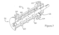
図6〜8には、本発明の第二の実施形態による、汚泥および炭質の変換のための装置50が示されている。
FIGS. 6 to 8 show an
装置50および装置10は実質的に同様であり、同じ番号は同じ部品を示す。装置50は、リアクター52およびその中で物質を運搬するためのコンベヤ手段、例えばコンベヤ54を含む。
リアクター52は同様に、汚泥入口20、ガス状生成物出口22および固体物質出口24を備えている。コンベヤ54の駆動装置36およびベアリング40、そして断熱材30が示されていないのと同様に、装置10の供給ホッパー16および炭化物ホッパー26は、装置50に関して示されていない。
The
図6で最もよく見えるように、リアクター52は再び2つのゾーン、加熱ゾーン32および反応ゾーン34に分けられる。汚泥/炭化物56のインベントリは、リアクター52内に示されている。コンベヤ54は、シャフト58およびその上に配置された複数のパドル60を含む。図7および8で最もよく見えるように、パドル60はシャフト58周囲にらせん状配置に装備され、半径方向に湾曲してそれぞれ「スコップ」を形成する。このコンベヤ配置により、少なくとも低いレベルの逆混合が誘発される。隣接パドル60は半径方向に72°で隔設される。隣接パドルは、半径方向に約30〜90°で隔設できることが想定される。
As best seen in FIG. 6,
リアクター52は、リアクター52内での炭化物56の保持を促進するために、再び堰62を備えている。堰62は再び、炭化物出口24の直前に備えられている。しかしながら堰62は、所望のWHSVが以前に決定されている場合のみ高さが固定される。堰62も、コンベヤ54の動作の結果として汚泥/炭化物床で生じる角度と実質的に一致または角度を模倣するために、コンベヤ54のシャフト58に関して、水平線に対して約30°の角度で傾斜または回転される。
The
シャフト/パドル構造、汚泥/炭化物床インベントリおよび形状、滞留時間および混合特性の調査を対象とした一連の試験のために、装置50のモデルを組立てた。
A model of the
モデルは、直径240mmのリアクターシェル、らせん状に取付けられたパドルを備えたコンベヤシャフト、およびペレットがある高さに達するまでペレットがリアクターから流出するのを防止する、リアクターの出口端の堰より成る。このモデルは、自動フィーダー下のフレームにボルト止めした。ギア式モーターを使用して、チェーンおよびスプロケット機構を介してリアクターのコンベヤシャフトを駆動させた。変速駆動装置(「VSD」)を使用してモーター速度を変更した。 The model consists of a reactor shell with a diameter of 240 mm, a conveyor shaft with helically attached paddles, and a weir at the outlet end of the reactor that prevents the pellet from flowing out of the reactor until it reaches a certain height. . This model was bolted to the frame under the automatic feeder. A geared motor was used to drive the conveyor shaft of the reactor through a chain and sprocket mechanism. The motor speed was changed using a variable speed drive ("VSD").
本試験に使用した手順は実質的に以下の通りであった。
・リアクターに既知の質量のペレットを充填する。
・VSDを調整して、所望のシャフト回転速度を与える。
・フィーダーを調整して、所望の供給量を与える。
・シャフト回転およびペレット供給を同時に開始する。
・リアクターを出る全てのペレットを収集する。
・運転30分後、リアクターを出た供給量を測定する。
・出た供給量が入った供給量と等しい場合、リアクターは定常状態に達している。リアクターが定常状態に達していない場合、定常状態に達するまで出た供給量の監視を続ける。
・定常状態に達するまでリアクターの運転を続け、次にペレット供給およびシャフト回転を同時に遮断する。
・自動フィーダーのロードセル読取値を記録する。
・リアクターから出たペレットの総質量を測定する。
The procedure used for this study was substantially as follows.
Fill the reactor with a known mass of pellets.
Adjust the VSD to give the desired shaft rotation speed.
Adjust the feeder to give the desired supply.
・ Start shaft rotation and pellet feeding at the same time.
Collect all pellets exiting the reactor.
• After 30 minutes of operation, measure the feed rate leaving the reactor.
• The reactor has reached a steady state when the amount of feed that has exited is equal to the amount of feed that has entered. If the reactor has not reached a steady state, continue to monitor the feed rate exited until it reaches a steady state.
Continue reactor operation until steady state is reached, then shut off pellet feed and shaft rotation simultaneously.
-Record the load cell reading of the automatic feeder.
• Measure the total mass of the pellets exiting the reactor.
ここで、床に蓄積した、または床から消耗されたペレットの質量を計算することができ、定常状態での最終床インベントリを見出すことができる。 Here, the mass of pellets accumulated on or consumed from the floor can be calculated, and the final floor inventory at steady state can be found.
次の段階は、滞留時間分布を見出すことであり、そのためにステップは実質的に以下の通りであった。
・既知の質量の着色ペレットをリアクター内部の、供給入口の下に置く。
・シャフト回転およびペレット供給を同時に開始する。
・5分間の画分で、リアクターを出たペレットを収集する。
・理論滞留時間の少なくとも2倍まで続ける。
・ペレット供給およびシャフト回転を同時に遮断する。
・各5分間の画分中の着色ペレットをカウントおよび秤量する。
The next step was to find the residence time distribution, so the steps were substantially as follows.
Place a known mass of colored pellets inside the reactor, below the feed inlet.
・ Start shaft rotation and pellet feeding at the same time.
Collect the pellets leaving the reactor in 5 minute fractions.
Continue to at least twice the theoretical residence time.
-Block pellet supply and shaft rotation at the same time.
Count and weigh the colored pellets in each 5 minute fraction.
この時点でリアクター内のペレットを秤量して、試験終了時の床インベントリを得た。パドルおよび堰の構造も、要件に応じて変更できる。このことは必ずしも必要でなく、そのような場合は、リアクターをスタンドに残し、運転条件(シャフト速度、ペレット供給量)を変更して、手順を最初から繰り返した。 At this point, the pellets in the reactor were weighed to obtain a floor inventory at the end of the test. The structure of the paddle and weir can also be changed according to requirements. This was not always necessary, in which case the procedure was repeated from the beginning, leaving the reactor on the stand, changing the operating conditions (shaft speed, pellet feed).
各試験に使用したリアクター構造および運転条件を以下の表1にまとめる。 The reactor structure and operating conditions used for each test are summarized in Table 1 below.
成功した試験のみを分析用に選択した−従って変なナンバリングシステムであった。 Only successful tests were selected for analysis-thus a strange numbering system.
床インベントリ
モデルリアクター用の設計床インベントリは、14Lである。すなわちインベントリは、リアクター内のペレットの、特定の体積として設計されている。そしてペレットの質量は、床の体積およびペレットのバルク密度の関数である。ペレットのバルク密度は、試験7B(500kg/m3)および試験9(426kg/m3)でのみ測定した。試験6および7Aで使用したペレットのバルク密度は、500kg/m3と仮定する必要があった。同じバッチからのペレットがリサイクルされて、大半の試験で使用され、試験終了に向けて交換されただけであるため、このことは妥当であることが予想される。
Floor inventory The design floor inventory for the model reactor is 14L. That is, the inventory is designed as a specific volume of pellets in the reactor. And the mass of the pellet is a function of the bed volume and the bulk density of the pellet. Bulk density of the pellets, only measured in the test 7B (500kg / m 3) and a test 9 (426kg / m 3). The bulk density of the pellets used in
リアクター内のペレットのバルク密度が、その測定したバルク密度と同様であったと仮定すると、各試験の床インベントリは、定常状態にある床内部のペレットの総質量から計算できる。床内のペレットの質量は、いったん定常状態に達すると(滞留時間試験の「前に」)、そして試験の終了時に(滞留時間試験の「後に」)変化した。これらの結果のどちらも、その平均と同様に、図9に示すように床インベントリを計算するのに使用された。 Assuming that the bulk density of the pellets in the reactor was similar to the measured bulk density, the floor inventory for each test can be calculated from the total mass of pellets inside the bed at steady state. The mass of pellets in the bed changed once steady state was reached (“before” the residence time test) and at the end of the test (“after” the residence time test). Both of these results, as well as the average, were used to calculate the floor inventory as shown in FIG.
これらの結果の解釈は、床インベントリの経時変化によって複雑になる。リアクターは、試験6および7Aでは空になり、試験7Bおよび9では充填されるように見える。各試験では定常状態への接近がほぼ同じだけの時間(〜1時間)を必要としたため、床インベントリの初期値は比較のために使用した。
Interpreting these results is complicated by changes in floor inventory over time. The reactor appears to be empty in
試験9と試験7Bとの初期床インベントリの相違は〜3Lである。これは非常に大きく、パドルの後方傾斜が初期床インベントリを上昇させることを示唆しているが、はるかに低いバルク密度と異なるリアクター構造の効果を分離することは困難である。床インベントリの小さい経時変化のために、試験9のリアクター構造および運転条件は、定常運転に最適であるように思われる。
The difference in initial floor inventory between
試験6と試験7Aとの間の床インベントリの増加は、約1Lである。試験7Aと7Bとの間の床インベントリの増加は、<0.3Lである。このことは、シャフト速度は初期床インベントリに対してほとんど〜全く影響を持たなかったのに対して、パドルおよび/または回転堰の数ははるかに大きな効果を有したことを意味する。試験6と試験7Aの間では、パドルのフライトの半分をリアクターから除去し、堰を傾斜させて床の角度と一致させた。これらの2つの変化はどちらもそれ自体で大きな効果を有したはずであるため、インベントリの増加をこれらの変化した変数の一方のみのせいであるとすることは、あまり妥当ではない。このことは、堰の角度が、新しいリアクターの運転のために不可欠な変数であるかどうかを、これらの結果から評価することが困難であることを意味している。しかしながら、堰を床と一列に並べることによって、堰の後ろの死角が著しく縮小されたことは明らかであった。このことは、床の大半は活動的であり、出口前に古い粉末状ペレットの蓄積はわずかであることを意味する。実際に観測から、傾斜した堰は、さらに「有用な」定常床(出口付近に)を作成する。
The increase in floor inventory between
床インベントリの経時変化は、シャフト速度およびパドル構成によって明確に影響される。床は試験7Aの間、シャフト速度が6rpmの時に消耗したのに対して、試験7B(4rpm)では、ペレットがリアクター内に蓄積した。供給量に相違があるが、試験7Bの間にリアクターに供給された全量は、試験7Aの間にリアクターに供給された全量よりも少なく、インベントリはなお増加する。これら2つの試験の唯一の相違は回転速度であり、従って速度が低下するにつれて、ペレットがリアクターから放出される速度が低下すると思われる。
Changes in floor inventory over time are clearly influenced by shaft speed and paddle configuration. The bed was consumed during
堰の目的は、30%の充填係数を与える14Lのペレット蓄積をリアクター内に提供することであった。したがって所望の充填係数は、試験7Aおよび7Bの構造によってほぼ達成され、試験9の構造によってさらに達成された。これら全ての試験で、バルク密度は、形状、従って床の体積に影響を及ぼすことによって、床インベントリの決定に大きな効果を有していた。試験9でのペレットの低いバルク密度(450−500kg/m3)は、床をリアクター内部に蓄積させ(大きな安息角)、実際に堰のレベルより上に存在させた。従ってこの構造は、これらの試験で充填係数を達成するために最良であったが、そのように大きな床インベントリを、より高いバルク密度ペレットと共に維持できない。より高いバルク密度のペレットは、16Lのインベントリを達成できないが、14Lの最低体積が達成できることが予測される。
The purpose of the weir was to provide 14 L of pellet accumulation in the reactor giving a 30% fill factor. Thus, the desired fill factor was almost achieved with the
従って充填係数を改善する方法を見つけるための、これらの実験で示された第一の目標が達成された。充填係数は、リアクター内のパドルの数を減少させることと、パドルをリアクター入口に向けて後方に傾斜させることによって上昇させることができる。特にパースペクスモデルでは、シャフト速度4rpm、パドルの半分のフライト(9)、およびパドルに対してやや(10°)背面角は、床体積を最大化する。 Therefore, the first goal shown in these experiments to find a way to improve the filling factor was achieved. The fill factor can be increased by reducing the number of paddles in the reactor and tilting the paddles back toward the reactor inlet. Particularly in the Perspex model, a shaft speed of 4 rpm, a half paddle flight (9), and a slight back angle with respect to the paddle (10 °) maximizes the floor volume.
パドルの数を減少させることにより引き起こされる床インベントリに対する影響はおそらく、リアクター内のプラスチックの減少した体積によって引き起こされないが、床に対する低下した外乱によって引き起こされる。「床外乱」と呼ばれるパラメータが提案される。これは、単位時間当たりの床の各部分における混合事象の回数のようなものである。それはパドルの数および回転速度の関数である。従ってパドルの数および回転速度を減少させることは、「床外乱」を減少させる。より大きいリアクターの最適パラメータは異なるが、法則は本質的に同じである−床外乱の減少は、床インベントリを増加させる。 The impact on floor inventory caused by reducing the number of paddles is probably not caused by the reduced volume of plastic in the reactor, but is caused by reduced disturbance to the floor. A parameter called “floor disturbance” is proposed. This is like the number of mixing events in each part of the floor per unit time. It is a function of the number of paddles and the rotational speed. Therefore, reducing the number of paddles and the rotational speed reduces the “floor disturbance”. Although the optimal parameters for larger reactors are different, the law is essentially the same-reducing floor disturbances increases bed inventory.
滞留時間−平均滞留時間
各試験の形式上および平均の滞留時間を、5%のペレットが出た時間と同様に、図10にまとめる。「形式上の」滞留時間は、瞬間曲線のピーク−すなわち大半のペレットが5分間の画分中に出た時間と見なした。「平均」滞留時間は、50%のペレットがリアクターを出た時間と見なした。
Residence time—Average residence time The format and average residence time for each test is summarized in FIG. 10 as well as the time at which 5% pellets were produced. The “formal” residence time was taken as the peak of the instantaneous curve—the time when most of the pellets were in the 5 minute fraction. The “average” residence time was taken as the time when 50% of the pellets exited the reactor.
この比較には、2つの主な誤差源−試験6の間の起こりうる短絡および試験9の平均滞留時間の過大見積りがある。
This comparison has an overestimate of the two main sources of error-possible short circuit between
試験6の間に、着色ペレットがリアクターを導入する時に、回転およびペレット供給を維持して、着色ペレットを供給入口の上部に注入した。ペレットがシャフトに当たると、ペレットはリアクターに沿って反発し、その一部は供給入口から少なくとも20cm(リアクター長の20%)離れて静止する。これは大量の短絡を引き起こし、実際の滞留時間を非常に低く見積もったはずである。
During
試験を完了させるために利用可能な時間が不十分であったために、試験9のデータは、20%までの蓄積質量しか利用できない。このことにより、平均滞留時間は、データを50%の蓄積質量に手作業で外挿して見出され、前と似た湾曲形状を取った。これは、実際の曲線がさらに理想的ならば、滞留時間を過大見積りするであろう。
Due to insufficient time available to complete the test, the
理想的な平均滞留時間を質量供給量で割った床インベントリ(kg)から計算する場合、予測された理想的な滞留時間を計算することができる。これらは以下の表2で、実験によって見出された実際の値と比較されている。 When calculating the ideal average residence time from the floor inventory (kg) divided by the mass feed rate, the predicted ideal residence time can be calculated. These are compared in Table 2 below with the actual values found by experiment.
試験6の結果を無視して、試験9の滞留時間が理想的な予測値とほぼ等しいと仮定した場合、ペレットは平均して、リアクター内に予測時間長に渡って残っていることが明らかと思われる。従って平均滞留時間は、理想的なプラグフローモデルに従うが、滞留時間分布は従わない。半分のフライトのパドルおよびシャフト速度4rpmの、試験7Bおよび9では、結果がさらに密接に理想に接近することに注目のことは興味深い。従って床インベントリの結果と同様に、所望の滞留時間は、床外乱を減少させる(すなわち回転速度および/またはパドルの数を減少させる)ことによって達成できる。
Neglecting the results of
滞留時間分布
各種の試験間で滞留時間分布を比較するために、瞬間および蓄積質量分率を平均滞留時間の関数としてプロットした。瞬間結果を得た各種の時間を、平均滞留時間のパーセンテージに変換した。このことは、図12に示すように、4つ全ての試験の結果を比較のために1セットの軸にプロットできることを意味する。非正規化結果を図11に示す。
Residence time distribution To compare the residence time distribution between the various tests, the instantaneous and accumulated mass fractions were plotted as a function of average residence time. The various times from which the instantaneous results were obtained were converted to a percentage of the average residence time. This means that the results of all four tests can be plotted on a set of axes for comparison, as shown in FIG. The denormalized result is shown in FIG.
滞留時間の関数としての蓄積質量%のグラフ、図12は、滞留時間分布が全て同様であることを明らかに示している。試験6の曲線は、値の最大の広がりを有し、最も理想的でない。試験7Bおよび試験9の結果は、最も鋭い湾曲を示し、理想に最も近い。曲線間の相違は、滞留時間の75%にて最大10質量%に達するが、特に大きくない。
A graph of accumulated mass% as a function of residence time, FIG. 12, clearly shows that the residence time distributions are all similar. The curve of
図13は、平均滞留時間の関数として瞬間質量%を与え、最後の3つの試験が完全に同様であるが、試験6の結果はさらに不安定であることを示す。試験6および試験7A〜9の間の大きな相違は、試験6にパドルのフライト全体を使用したことである。これはより乏しい滞留時間分布を引き起こしたか、または引き起こさなかった。リアクター構造または運転条件によってよりも、試験中にペレットをリアクターに滴下することによって、このことがさらに引き起こされたと考えられる。
FIG. 13 gives the instantaneous mass% as a function of the average residence time and shows that the last three tests are completely similar, but the results of
これらの結果から明らかなことは、滞留時間分布が本質的に同じであるために、シャフト回転速度およびパドル角度の変化がリアクター内での逆混合、短絡、および一般的なペレット運動の相対量に著しい影響を与えなかったことである。実際の流路が、ペレットが流路に沿って移動する速度を変えなかっただけであることが推測できる。 From these results it is clear that because the residence time distribution is essentially the same, changes in shaft rotational speed and paddle angle are related to the relative amounts of backmixing, short-circuiting, and general pellet motion in the reactor. It did not have a significant impact. It can be inferred that the actual channel only did not change the speed at which the pellets moved along the channel.
滞留時間を延長する方法を見つける、この実験で示された第二の目標が達成されている。最短および平均滞留時間は、シャフト上のパドルの数を減少させることと、パドルを入口に向けて後方に傾けることによって延長することができる。滞留時間は、床インベントリを増加することによっても改善され、これは次にシャフト速度を低下させることによって実現される。 The second goal shown in this experiment, finding a way to extend the residence time, has been achieved. The minimum and average dwell times can be extended by reducing the number of paddles on the shaft and tilting the paddles back toward the inlet. Residence time is also improved by increasing the floor inventory, which is then achieved by lowering the shaft speed.
モデルリアクターでは、計算した「理想的な」滞留時間は、6rpm未満の速度に近づけられ、半分のフライトのパドルをシャフトに取付けた。他のリアクターのサイズおよび構造について、適切な滞留時間に達した時点を判定するために実験が必要であることが理解されるものとする。 In the model reactor, the calculated “ideal” dwell time was brought close to a speed of less than 6 rpm and a half flight paddle was attached to the shaft. It should be understood that for other reactor sizes and configurations, experimentation is required to determine when the appropriate residence time has been reached.
床形状
全ての試験で、床を水平線に対して約30°の角度で(すなわち直径断面を通じて)回転させた。これは、ペレットをリアクターの片側に積み上げるパドルの押し動作によって引き起こされた。この角度は床に沿って一定であり、堰を同じ方向に回転することによって、その角度にリアクターを合わせた。
Floor shape In all tests, the floor was rotated at an angle of about 30 ° with respect to the horizon (ie through the diameter cross section). This was caused by the pushing action of the paddles that stacked the pellets on one side of the reactor. This angle was constant along the floor and the reactor was adjusted to that angle by rotating the weir in the same direction.
リアクター(入口と出口の間)に沿った床の高さは、いったん定常状態に達すると大きく変化しなかった。供給量が増加し、回転速度が低下すると、ペレットがリアクターの入口端に蓄積する傾向が多少あった。大半の場合ではこの蓄積は、端高さより5〜8cmを超えることのない、管理可能な高さに達した。高さの相違がこれを超えた場合、パドルは床の中に完全に沈むようになり、駆動システムに対して過剰なトルクを引き起こし、試験を打ち切りにさせる。このことは試験8の間に発生し、試験8ではパドルの両方のフライトがシャフトに設置されていた。多数のパドルは、高レベルの逆混合を引き起こした。システムに供給がない場合は、パドルは回転できたが、ペレットがリアクターに供給されるとすぐに、ペレットは、入口端に蓄積を開始した。この蓄積は、数回除去されたにもかかわらず、管理できなくなり、シャフトに対するトルクは、駆動システムの故障を引き起こすほど大きかった。試験8は打ち切りにした。 The bed height along the reactor (between the inlet and outlet) did not change significantly once steady state was reached. As the feed rate increased and the rotational speed decreased, there was some tendency for the pellets to accumulate at the inlet end of the reactor. In most cases, this accumulation reached a manageable height that did not exceed 5-8 cm beyond the edge height. If the height difference exceeds this, the paddle will sink completely into the floor, causing excessive torque to the drive system and aborting the test. This occurred during test 8, where both paddle flights were installed on the shaft. Many paddles caused high levels of backmixing. In the absence of feed to the system, the paddle was able to rotate, but as soon as the pellets were fed into the reactor, the pellets started to accumulate at the inlet end. This buildup was unmanageable despite being removed several times, and the torque on the shaft was so great as to cause drive system failure. Test 8 was censored.
これはより少ない供給量(4kg/時)の理由でもあった−実験に使用した低いシャフト回転速度では、より大きい供給量が十分に運搬され、過剰な床蓄積を引き起こした。 This was also the reason for the lower feed rate (4 kg / hr)-at the lower shaft speed used in the experiment, the larger feed rate was well carried and caused excessive bed buildup.
全ての実験で、床は、正弦曲線のようなわずかな「波」を生じさせた。この床の永久波形が、パドル数、そして回転速度が減少するにつれてさらに強調されるようになった。従って試験6では、ごく小さな波動があるが、試験9によっては非常に顕著であった。
In all experiments, the floor produced a slight “wave” like a sinusoid. The permanent waveform of this floor became more pronounced as the paddle number and rotational speed decreased. Therefore, in
床混合および逆混合
パドルの動作によって、ペレットはよく混合されて床に入った。逆混合の程度は、確認するのが困難であった。ペレットは前方に(すなわちリアクターの放出に向かって)迅速に移動しなかったが、上述した理由によって打ち切られたダブルフライト試験(試験8)を除いて、それらが後方に(すなわちリアクターの入口に向かって)移動した証拠はなかった。起こると思われたことは、パドルによって収集されたペレットの各ひとすくいの量のうち、50%が前方に落下し、50%が後方に落下することであった。2個のパドル間の同じ小さなゾーン内のペレットの一部を、それらが最終的に前方に移動する前に、一定期間保持する。パドルのらせん状間隔は、リアクター入口から放出に向かって移動する回転波を生じさせた。
Bed mixing and back mixing The paddle operation mixed the pellets well into the bed. The degree of backmixing was difficult to confirm. The pellets did not move rapidly forward (ie towards the discharge of the reactor), but they moved backwards (ie towards the reactor inlet) except for the double flight test (test 8) which was censored for the reasons described above. There was no evidence of movement. What seemed to happen was that 50% of the amount of each scoop of pellets collected by the paddle fell forward and 50% fell backward. Part of the pellet in the same small zone between the two paddles is held for a period of time before they finally move forward. The helical spacing of the paddles produced a rotating wave that moved from the reactor inlet towards the discharge.
逆混合は、高温ガスおよび低温ペレットの流れが逆流であるため、熱移動にとって問題となることがある。従って温かいペレットがリアクター入口端に向かって逆移動する場合には、加熱ジャケット内の燃焼排ガスとリアクター内のペレットとの温度差は減少する。しかしながら、逆混合が狭い範囲内のみで起きる場合、ペレットの温度特性は著しく影響されず、熱移動に有害な影響はない。ペレットは通例、パドルによって小さいゾーン内にのみ保持される。 Backmixing can be problematic for heat transfer because the flow of hot gas and cold pellets is backflow. Therefore, when the warm pellet moves backward toward the reactor inlet end, the temperature difference between the flue gas in the heating jacket and the pellet in the reactor decreases. However, if backmixing occurs only within a narrow range, the temperature characteristics of the pellets are not significantly affected and there is no detrimental effect on heat transfer. Pellets are typically held only in small zones by paddles.
実験の2つの目標は、床インベントリおよびペレット滞留時間を増加させることであった。これらの両方は、パドルの数を減少させることと、シャフト速度を低下させることによって改良できることが見出された。パドルを入口に向かって後方に傾斜させることも、かなりの改良を実現した。最低限のペレット突破時間を達成するのに必要なリアクター構造および運転条件も既知であるので、短絡が最小限の、最短保持時間を与えるようなリアクターを設計できる。 The two goals of the experiment were to increase bed inventory and pellet residence time. It has been found that both of these can be improved by reducing the number of paddles and reducing the shaft speed. Inclining the paddle back towards the entrance also realized a significant improvement. Since the reactor structure and operating conditions necessary to achieve the minimum pellet breakthrough time are also known, a reactor can be designed that provides the shortest hold time with minimal short circuit.
上の議論から、良好な熱移動および物質移動の両方のために乾燥汚泥の良好な混合を行うと共に、「短絡」も最小限に抑え、汚泥/炭化物床を空にするために、所定のWHSVを用いて、本発明による装置および方法を設計するのが可能であることがわかる。汚泥/炭化物インベントリの良好な制御は、達成可能であり、熱移動に関して最も重要なことに、5%未満の炭化物が40分以内に通過し、出願人はこれを、炭化物を450℃まで加熱するために必要な時間として理解している。 From the above discussion, to achieve a good mixing of dry sludge for both good heat transfer and mass transfer, while also minimizing “short circuit” and emptying the sludge / carbide bed, a given WHSV Can be used to design an apparatus and method according to the present invention. Good control of the sludge / carbide inventory is achievable, and most importantly with respect to heat transfer, less than 5% of the carbide passes within 40 minutes, and Applicants heat it to 450 ° C. Understand as necessary time.
約2〜8m/分のパドル先端速度は、直径240mmの本発明のモデル装置で十分な熱移動および物質移動を提供する。これらの調査の結果の「スケールアップ」は、供給量25tpdの直径1メートルのリアクターでは、良好な熱移動および物質移動のためには、わずか1〜2rpmのコンベヤ回転が必要なことを意味すると想定される。さらに、汚泥/炭化物床に沿って均質な混合を提供するために、パドル先端速度を一定に維持することが望ましい。 A paddle tip speed of about 2-8 m / min provides sufficient heat and mass transfer with the model device of the present invention having a diameter of 240 mm. The “scale-up” of the results of these studies assumes that a 1 meter diameter reactor with a feed rate of 25 tpd requires only 1-2 rpm conveyor rotation for good heat and mass transfer. Is done. In addition, it is desirable to keep the paddle tip speed constant in order to provide homogeneous mixing along the sludge / carbide bed.
当業者に明白であるような変更および変形は、本発明の範囲内に入ると見なされる。 Modifications and variations as will be apparent to those skilled in the art are deemed to be within the scope of the present invention.
Claims (28)
(a)油生成蒸気の気化のために、酸素の非存在下でリアクターの加熱ゾーンで変換される物質を加熱し、それにより蒸気生成物および固体残留物または炭化物の両方を生成するステップと、
(b)気相触媒反応を促進するために、リアクターの反応ゾーンで、決定された毎時重量空間速度にて蒸気生成物および炭化物を接触させるステップと、
(c)ガス状生成物および炭化物をリアクターから除去および分離するステップと
を含むことを特徴とする方法。 A method for the conversion of sludge and charcoal,
(A) heating the material to be converted in the heating zone of the reactor in the absence of oxygen for the vaporization of oil-producing steam, thereby producing both a steam product and a solid residue or carbide;
(B) contacting the vapor product and carbide at a determined hourly weight space velocity in the reaction zone of the reactor to promote a gas phase catalytic reaction;
(C) removing and separating gaseous products and carbides from the reactor.
An apparatus for the conversion of sludge and charcoal substantially as described above with reference to FIGS.
Applications Claiming Priority (2)
| Application Number | Priority Date | Filing Date | Title |
|---|---|---|---|
| AU2002951194A AU2002951194A0 (en) | 2002-09-04 | 2002-09-04 | Conversion of sludges and carbonaceous materials |
| PCT/AU2003/001099 WO2004022673A1 (en) | 2002-09-04 | 2003-08-26 | Conversion of sludges and carbonaceous materials |
Publications (2)
| Publication Number | Publication Date |
|---|---|
| JP2005537368A true JP2005537368A (en) | 2005-12-08 |
| JP2005537368A5 JP2005537368A5 (en) | 2006-10-12 |
Family
ID=28047162
Family Applications (1)
| Application Number | Title | Priority Date | Filing Date |
|---|---|---|---|
| JP2004533047A Pending JP2005537368A (en) | 2002-09-04 | 2003-08-26 | Sludge and charcoal conversion |
Country Status (5)
| Country | Link |
|---|---|
| US (1) | US20070043246A1 (en) |
| EP (1) | EP1546287A1 (en) |
| JP (1) | JP2005537368A (en) |
| AU (1) | AU2002951194A0 (en) |
| WO (1) | WO2004022673A1 (en) |
Cited By (1)
| Publication number | Priority date | Publication date | Assignee | Title |
|---|---|---|---|---|
| JP2017517384A (en) * | 2014-04-15 | 2017-06-29 | フラウンホーファー−ゲゼルシャフト ツル フェルデルング デル アンゲヴァンテン フォルシュング エー ファウFraunhofer−Gesellschaft zur Foerderung der angewandten Forschung e.V. | Apparatus and method for thermal contact treatment of material and pyrolysis oil produced thereby |
Families Citing this family (10)
| Publication number | Priority date | Publication date | Assignee | Title |
|---|---|---|---|---|
| US7909895B2 (en) | 2004-11-10 | 2011-03-22 | Enertech Environmental, Inc. | Slurry dewatering and conversion of biosolids to a renewable fuel |
| US20070012232A1 (en) * | 2005-04-27 | 2007-01-18 | Winterbrook Investment Partners, Llc | System and Methods for Organic Material Conversion and Energy Generation |
| WO2006117934A1 (en) * | 2005-04-27 | 2006-11-09 | Mitsubishi Kakoki Kaisha, Ltd. | Organic waste disposal facility and method of disposal |
| WO2007002113A1 (en) * | 2005-06-20 | 2007-01-04 | Winterbrook Investment Partners, Llc | Systems and methods for organic material conversion and energy generation |
| GB0704619D0 (en) * | 2007-03-09 | 2007-04-18 | E D C Uk Ltd | Waste management system |
| US8377155B2 (en) * | 2008-02-20 | 2013-02-19 | Robert C. Tyer | Auger gasifier with continuous feed |
| CA2638152C (en) * | 2008-07-24 | 2013-07-16 | Sunopta Bioprocess Inc. | Method and apparatus for treating a cellulosic feedstock |
| BRPI1000208A2 (en) | 2010-01-29 | 2011-01-04 | Sppt Pesquisas Tecnologicas Ltda | low temperature conversion vibrant heat exchanger equipment for organic waste treatment and organic waste treatment process by employing low temperature conversion vibrant heat exchanger equipment |
| IT1400225B1 (en) | 2010-04-15 | 2013-05-24 | Eni Spa | PROCEDURE FOR THE PRODUCTION OF BIO-OIL FROM URBAN SOLID WASTE |
| CN105874038B (en) * | 2013-12-16 | 2022-01-25 | 雷内吉公司 | Apparatus for pyrolysing carbonaceous material |
Citations (4)
| Publication number | Priority date | Publication date | Assignee | Title |
|---|---|---|---|---|
| JPS59132933A (en) * | 1983-01-21 | 1984-07-31 | Sankyo Yuki Kk | Thermally decomposing reaction apparatus using particulate ore substance |
| JPS6099399A (en) * | 1983-09-13 | 1985-06-03 | ハー・マジエステイ・イン・ライト・オブ・カナダ | Method and device for changing sludge |
| JPH10328641A (en) * | 1997-05-30 | 1998-12-15 | Nkk Corp | Process and device for treating chlorine-containing resin |
| JP2000008045A (en) * | 1998-06-23 | 2000-01-11 | Meidensha Corp | Treatment of material containing harmful component and treating apparatus |
Family Cites Families (3)
| Publication number | Priority date | Publication date | Assignee | Title |
|---|---|---|---|---|
| US5865965A (en) * | 1994-02-01 | 1999-02-02 | Kabushiki Kaisha Toshiba | Apparatus for electrochemical decontamination of radioactive metallic waste |
| AUPN910296A0 (en) * | 1996-04-03 | 1996-05-02 | Environmental Solutions International Ltd | Process and apparatus for the conversion of sludge |
| AUPP936099A0 (en) * | 1999-03-22 | 1999-04-15 | Environmental Solutions International Ltd | Process and apparatus for the conversion of carbonaceous materials |
-
2002
- 2002-09-04 AU AU2002951194A patent/AU2002951194A0/en not_active Abandoned
-
2003
- 2003-08-26 JP JP2004533047A patent/JP2005537368A/en active Pending
- 2003-08-26 WO PCT/AU2003/001099 patent/WO2004022673A1/en active Application Filing
- 2003-08-26 EP EP03793465A patent/EP1546287A1/en not_active Withdrawn
- 2003-08-26 US US10/526,714 patent/US20070043246A1/en not_active Abandoned
Patent Citations (4)
| Publication number | Priority date | Publication date | Assignee | Title |
|---|---|---|---|---|
| JPS59132933A (en) * | 1983-01-21 | 1984-07-31 | Sankyo Yuki Kk | Thermally decomposing reaction apparatus using particulate ore substance |
| JPS6099399A (en) * | 1983-09-13 | 1985-06-03 | ハー・マジエステイ・イン・ライト・オブ・カナダ | Method and device for changing sludge |
| JPH10328641A (en) * | 1997-05-30 | 1998-12-15 | Nkk Corp | Process and device for treating chlorine-containing resin |
| JP2000008045A (en) * | 1998-06-23 | 2000-01-11 | Meidensha Corp | Treatment of material containing harmful component and treating apparatus |
Cited By (2)
| Publication number | Priority date | Publication date | Assignee | Title |
|---|---|---|---|---|
| JP2017517384A (en) * | 2014-04-15 | 2017-06-29 | フラウンホーファー−ゲゼルシャフト ツル フェルデルング デル アンゲヴァンテン フォルシュング エー ファウFraunhofer−Gesellschaft zur Foerderung der angewandten Forschung e.V. | Apparatus and method for thermal contact treatment of material and pyrolysis oil produced thereby |
| US10414987B2 (en) | 2014-04-15 | 2019-09-17 | Fraunhofer-Gesellschaft zur Förderung der angewandten Forschung e.V. | System and method for thermocatalytic treatment of material and pyrolysis oil produced therewith |
Also Published As
| Publication number | Publication date |
|---|---|
| EP1546287A1 (en) | 2005-06-29 |
| WO2004022673A1 (en) | 2004-03-18 |
| US20070043246A1 (en) | 2007-02-22 |
| AU2002951194A0 (en) | 2002-10-03 |
Similar Documents
| Publication | Publication Date | Title |
|---|---|---|
| Campuzano et al. | Auger reactors for pyrolysis of biomass and wastes | |
| JP5734230B2 (en) | Waste treatment method and apparatus | |
| US6698365B2 (en) | Apparatus for thermal treatment using superheated steam | |
| JP2005537368A (en) | Sludge and charcoal conversion | |
| US9476003B2 (en) | Coal enhancement process | |
| WO2008005476A2 (en) | Method and system for accomplishing flash or fast pyrolysis with carbonaceous materials | |
| AU2007269665A1 (en) | Method and system for accomplishing flash or fast pyrolysis with carbonaceous materials | |
| JP2003504454A5 (en) | ||
| US20070012232A1 (en) | System and Methods for Organic Material Conversion and Energy Generation | |
| KR20060100022A (en) | Method for manufacturing energy from combustible waste non pollution carbonization, the system therefor, cracking catalyst and manufacturing method thereof | |
| JP5504959B2 (en) | Sludge carbonization equipment | |
| US20070007188A1 (en) | Systems and methods for organic material conversion and use | |
| JP4908874B2 (en) | Gasification apparatus, hardly decomposable organic compound processing apparatus and processing method | |
| WO1994002780A1 (en) | Apparatus for allowing thermal dimensional changes of metal parts in a retort mechanism | |
| KR20210093881A (en) | Method and apparatus for treating carbon-containing material | |
| WO2017209638A1 (en) | Method and installation for thermochemical conversion of raw material containing organic compounds | |
| JP4756556B2 (en) | Sludge carbonization equipment | |
| US5735224A (en) | Thermal dechlorinating apparatus and method for collected ash | |
| WO2007002113A1 (en) | Systems and methods for organic material conversion and energy generation | |
| JP4077811B2 (en) | Heat treatment equipment using superheated steam | |
| JP2000249317A (en) | Method for melting solid refuse | |
| AU2003254399A1 (en) | Conversion of sludges and carbonaceous materials | |
| JP2004060927A (en) | Sludge incinerating method and incinerating equipment using fluidized incinerator | |
| CA2723601A1 (en) | Method and apparatus for efficient production of activated carbon | |
| AU2015202493B2 (en) | Coal enhancement process |
Legal Events
| Date | Code | Title | Description |
|---|---|---|---|
| A521 | Request for written amendment filed |
Free format text: JAPANESE INTERMEDIATE CODE: A523 Effective date: 20060822 |
|
| A621 | Written request for application examination |
Free format text: JAPANESE INTERMEDIATE CODE: A621 Effective date: 20060822 |
|
| A977 | Report on retrieval |
Free format text: JAPANESE INTERMEDIATE CODE: A971007 Effective date: 20090428 |
|
| A131 | Notification of reasons for refusal |
Free format text: JAPANESE INTERMEDIATE CODE: A131 Effective date: 20091120 |
|
| A02 | Decision of refusal |
Free format text: JAPANESE INTERMEDIATE CODE: A02 Effective date: 20100427 |