JP2005536009A - Automatic electrical wedge connector - Google Patents

Automatic electrical wedge connector Download PDF

Info

Publication number
JP2005536009A
JP2005536009A JP2004512236A JP2004512236A JP2005536009A JP 2005536009 A JP2005536009 A JP 2005536009A JP 2004512236 A JP2004512236 A JP 2004512236A JP 2004512236 A JP2004512236 A JP 2004512236A JP 2005536009 A JP2005536009 A JP 2005536009A
Authority
JP
Japan
Prior art keywords
wedge
shell
connector
opposing
conductor
Prior art date
Legal status (The legal status is an assumption and is not a legal conclusion. Google has not performed a legal analysis and makes no representation as to the accuracy of the status listed.)
Pending
Application number
JP2004512236A
Other languages
Japanese (ja)
Other versions
JP2005536009A5 (en
Inventor
メロー、キース・エフ
ドブリンスキ、ダニエル・ディー
ステルツァー、ゴードン・エル
Original Assignee
エフシーアイ
Priority date (The priority date is an assumption and is not a legal conclusion. Google has not performed a legal analysis and makes no representation as to the accuracy of the date listed.)
Filing date
Publication date
Application filed by エフシーアイ filed Critical エフシーアイ
Publication of JP2005536009A publication Critical patent/JP2005536009A/en
Publication of JP2005536009A5 publication Critical patent/JP2005536009A5/ja
Pending legal-status Critical Current

Links

Images

Classifications

    • HELECTRICITY
    • H01ELECTRIC ELEMENTS
    • H01RELECTRICALLY-CONDUCTIVE CONNECTIONS; STRUCTURAL ASSOCIATIONS OF A PLURALITY OF MUTUALLY-INSULATED ELECTRICAL CONNECTING ELEMENTS; COUPLING DEVICES; CURRENT COLLECTORS
    • H01R4/00Electrically-conductive connections between two or more conductive members in direct contact, i.e. touching one another; Means for effecting or maintaining such contact; Electrically-conductive connections having two or more spaced connecting locations for conductors and using contact members penetrating insulation
    • H01R4/28Clamped connections, spring connections
    • H01R4/50Clamped connections, spring connections utilising a cam, wedge, cone or ball also combined with a screw
    • H01R4/5083Clamped connections, spring connections utilising a cam, wedge, cone or ball also combined with a screw using a wedge
    • YGENERAL TAGGING OF NEW TECHNOLOGICAL DEVELOPMENTS; GENERAL TAGGING OF CROSS-SECTIONAL TECHNOLOGIES SPANNING OVER SEVERAL SECTIONS OF THE IPC; TECHNICAL SUBJECTS COVERED BY FORMER USPC CROSS-REFERENCE ART COLLECTIONS [XRACs] AND DIGESTS
    • Y10TECHNICAL SUBJECTS COVERED BY FORMER USPC
    • Y10TTECHNICAL SUBJECTS COVERED BY FORMER US CLASSIFICATION
    • Y10T24/00Buckles, buttons, clasps, etc.
    • Y10T24/39Cord and rope holders
    • Y10T24/3969Sliding part or wedge

Landscapes

  • Connector Housings Or Holding Contact Members (AREA)
  • Suspension Of Electric Lines Or Cables (AREA)
  • Connections Effected By Soldering, Adhesion, Or Permanent Deformation (AREA)
  • Electric Cable Installation (AREA)
  • Multi-Conductor Connections (AREA)

Abstract

電気ウェッジコネクタ10は、シェル12及びウェッジ14、16を有する。このシェル12は、その中にウェッジ受入通路30、32を定める。このウェッジ14、16は、ウェッジ受入通路30、32に挿入されたときに、シェル23に対してくさび止めするように形づくられる。このウェッジ14、16は、ウェッジ14、16が、シェル内にくさび止めされるときに、シェル内に導体A、Bを受入れてしっかりと保持するためにその中に導体受入チャネルを有する。シェル12は、ウェッジが前記シェルの第1の部分にくさび止めされるときに、ウェッジ14、16に第1のクランプ力を生じる第1の曲げ剛性を有する第1の部分を具備する。シェル12は、ウェッジ14、16が前記シェルの第2の部分にくさび止めされるときに、ウェッジ内に第2のクランプ力を生じる第2の曲げ剛性を有する第2の部分を具備する。The electrical wedge connector 10 has a shell 12 and wedges 14 and 16. The shell 12 defines wedge receiving passages 30, 32 therein. The wedges 14 and 16 are shaped to wedge against the shell 23 when inserted into the wedge receiving passages 30 and 32. The wedges 14 and 16 have conductor receiving channels therein for receiving and firmly holding the conductors A and B in the shell when the wedges 14 and 16 are wedged into the shell. The shell 12 includes a first portion having a first bending stiffness that produces a first clamping force on the wedges 14, 16 when the wedge is wedged onto the first portion of the shell. The shell 12 includes a second portion having a second bending stiffness that produces a second clamping force in the wedge when the wedges 14, 16 are wedged to the second portion of the shell.

Description

この発明は、電気ウェッジコネクタに関し、特には改良された自動的な電気ウェッジコネクタに関する。   The present invention relates to electrical wedge connectors, and more particularly to an improved automatic electrical wedge connector.

スプライス、レジューサ、又はデッドエンドコネクタのような電力コネクタは、電気使用契約者、電気公益事業、及び地方自治体のような多様なユーザーによって、電力供給導体を接続するために使用される。装着は非常に困難なアクセスであり、気象条件であり、ことによっては頭上の活線のある屋外で完成する必要があり、この装着を容易にするために、ユーザーは、自動的な頭上コネクタを使用してきている。自動的な頭上コネクタにおいて、このコネクタの電力導体を保持するウェッジは、コネクタ内に自動的にウェッジをスプリング付勢して強制する。ウェッジと導体との間の導体の張力(導体の重量のため)及び摩擦は、それによってコネクタ内にウェッジをくさび止めする係留をなす。さらなる単純な装着のために、頭上の電力コネクタは、通常多様な寸法の多数の導体とともに使用されるように寸法採りされる。例えば、1本の頭上コネクタは、0.23インチ径から0.57インチ径超の導体を接続するために用いられる。このことは、ユーザーが選択して、作業現場でより少数の異なる寸法のコネクタを持っていくことができるものである。既知の頭上電力コネクタの構造は、コネクタとともに使用される最大の寸法の導体を接続する時、最大の接続負荷(例えば、ウェッジからコネクタシェルに対する負荷をてこであげるように)を支持することができる。したがって、コネクタの構造は、このように寸法採りされる。米国特許第60762336号は、くさび止め作用によってケーブルを握持するための対向するあごを支持する本体、及びケーブルを離脱するための開放位置にあごを保持するためのラッチプレートを有する従来のケーブルコネクタの例を開示する。従来のコネクタの他の例が、コネクタがその中に摺動可能に支持された握持あごを有する凹所を具備する本体を有する米国特許第4428100号に開示されている。このあごは、解放ピンによって開放位置に保持される。なお、さらに他の例が、米国特許5539961号に開示され、あごでスプリング負荷のウェッジデッドエンドが、フロータのタブよって開放をロックされる閉止位置スプリング閉止位置に対してスプリング付勢されている。この発明は、以下により詳細に述べるように、従来のコネクタの問題を解決することができる。   Power connectors, such as splices, reducers, or dead end connectors, are used to connect power supply conductors by a variety of users, such as electricity subscribers, utilities, and local governments. Wearing is a very difficult access, weather conditions, and sometimes needs to be completed outdoors with overhead overhead, and to facilitate this wearing, the user must install an automatic overhead connector Have been using. In an automatic overhead connector, the wedge holding the power conductor of the connector automatically springs and forces the wedge into the connector. Conductor tension between the wedge and the conductor (due to the weight of the conductor) and friction thereby mooring the wedge in the connector. For further simple wearing, overhead power connectors are usually sized for use with multiple conductors of varying dimensions. For example, one overhead connector is used to connect conductors from 0.23 inch diameter to more than 0.57 inch diameter. This allows the user to select and take a smaller number of different sized connectors at the work site. Known overhead power connector constructions can support the maximum connection load (eg, leverage the load from the wedge to the connector shell) when connecting the largest size conductors used with the connector. . The connector structure is thus dimensioned in this way. U.S. Pat. No. 6,072,336 discloses a conventional cable connector having a body that supports opposing jaws for gripping the cable by a wedge stop and a latch plate for holding the jaws in an open position for disconnecting the cable. An example of this is disclosed. Another example of a conventional connector is disclosed in U.S. Pat. No. 4,428,100 having a body with a recess having a gripping jaw in which the connector is slidably supported. The jaw is held in the open position by a release pin. Yet another example is disclosed in U.S. Pat. No. 5,539,961, in which the spring loaded wedge dead end is spring biased against a closed position, which is locked open by a floater tab. The present invention can solve the problems of conventional connectors as described in more detail below.

この発明の第1の実施例によれば、電気ウェッジコネクタが、提供される。   According to a first embodiment of the present invention, an electrical wedge connector is provided.

このコネクタは、シェル及びウェッジを有する。このシェルは、その中にウェッジ受入通路を定める。このウェッジは、前記ウェッジ受入通路内に挿入されるときに、前記シェルに対してくさび止めするように形付けられる。ウェッジは、前記シェル内にくさび止めされるときにその中にシェル内に導体を受入れてしっかりと保持するための導体受入チャネルを有する。前記シェルは、前記ウェッジがシェルの第1部分にくさび止めされるときにウェッジに第1のクランプ力を発生する第1の曲げ剛性を有する第1部分を具備する。ウェッジは、ウェッジがシェルの第2部分にくさび止めされるときにウェッジに第2のクランプ力を発生する第2の曲げ剛性を有する第2部分を具備する。 The connector has a shell and a wedge. The shell defines a wedge receiving passage therein. The wedge is shaped to wedge against the shell when inserted into the wedge receiving passage. The wedge has a conductor receiving channel for receiving and securely holding the conductor within the shell when wedged therein. The shell includes a first portion having a first bending stiffness that generates a first clamping force on the wedge when the wedge is wedged to the first portion of the shell. The wedge includes a second portion having a second bending stiffness that generates a second clamping force on the wedge when the wedge is wedged to the second portion of the shell.

この発明の第2の実施例によれば、電気ウェッジコネクタが提供される。コネクタは、フレーム及びウェッジを有する。このフレームは、その間にウェッジ受入通路を定める対向する壁を有する少なくとも1つのシェル区分を有する。   According to a second embodiment of the invention, an electrical wedge connector is provided. The connector has a frame and a wedge. The frame has at least one shell section having opposing walls defining a wedge receiving passage therebetween.

このウェッジは、前記ウェッジ受入通路内に挿入されるときに、前記シェルの対向する壁に対してくさび止めするように形付けられる。ウェッジは、前記シェル内にくさび止めされるときにその中にシェル内に導体を受入れてしっかりと保持するための導体受入チャネルを有する。前記シェルの対向する壁は、それから決まるスチフナを有する。このスチフナは、隣接するスチフナ間に等しくない空間を有する対向する壁の少なくとも1つに沿って供給される。 The wedge is shaped to wedge against the opposing walls of the shell when inserted into the wedge receiving passage. The wedge has a conductor receiving channel for receiving and securely holding the conductor within the shell when wedged therein. The opposing walls of the shell have stiffeners determined therefrom. The stiffener is fed along at least one of the opposing walls having an unequal space between adjacent stiffeners.

この発明による他の実施例によれば、電気ウェッジコネクタが、提供される。   According to another embodiment according to the present invention, an electrical wedge connector is provided.

このコネクタは、シェル及びウェッジを有する。このシェルは、その中に形成されたウェッジ受入通路を有する。このウェッジは、前記シェル内に導体を収容するための前記ウェッジ受入通路内にくさび止めされるようにされる。前記シェルは、前記シェル内に収容された導体が電線張り滑車装置を越えて引かれるときに、前記電線張り滑車装置内に前記ウェッジコネクタをガイドするための丸い外部ガイド面を有する第1端を有する。 The connector has a shell and a wedge. The shell has a wedge receiving passage formed therein. The wedge is wedged in the wedge receiving passage for receiving a conductor in the shell. The shell has a first end having a round external guide surface for guiding the wedge connector in the wire tensioning pulley device when a conductor contained in the shell is pulled over the wire tension pulley device. Have.

この発明のさらに他の実施例によれば、電気コネクタが提供される。コネクタは、フレーム及び1対の対向するウェッジ部材を有する。このフレームは、ウェッジ受入チャネルを有するシェルを有する。この1対の対向するウェッジ部材は、シェル内に導体をクランプするためのウェッジ受入チャネル内に位置される。1対の対向するウェッジ部材の少なくとも1つのウェッジ部材は、離隔絶縁器で対向するウェッジ部材と接触して保持する離隔絶縁器の突出部を有する。この隔離絶縁器の突出部は、対向するウェッジ部材と接触し、少なくとも1つのウェッジ部材からの2つの異なる離隔絶縁器で対向するウェッジ部材を保持する2つの停止表面を有する。   According to yet another embodiment of the invention, an electrical connector is provided. The connector has a frame and a pair of opposing wedge members. The frame has a shell with a wedge receiving channel. The pair of opposing wedge members are positioned in a wedge receiving channel for clamping a conductor in the shell. At least one wedge member of the pair of opposing wedge members has a spacing insulator protrusion that is held in contact with the facing wedge member by the spacing insulator. The protrusion of the isolation insulator has two stop surfaces that contact the opposing wedge member and hold the opposing wedge member with two different isolation insulators from the at least one wedge member.

この発明の前述した態様及びその他の特徴は、付属する図と関連してなされる以下の記述に置いて説明される。   The foregoing aspects and other features of the invention are described in the following description, taken in conjunction with the accompanying drawings.

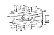
図1を参照して、この発明の特徴を具体化した電気ウェッジコネクタ10と2本の導体A、Bとの分解斜視図が示されている。この発明は図に示された単一の実施例に関連して説明されるが、この発明は、多くの他の実施例の形状に具体化されることを理解すべきである。さらに、部品又は材料のあらゆる適切な寸法、形状又はタイプでも使用することができる。   Referring to FIG. 1, an exploded perspective view of an electrical wedge connector 10 and two conductors A and B embodying features of the present invention is shown. While the invention will be described in connection with the single embodiment shown in the drawings, it should be understood that the invention is embodied in the form of many other embodiments. Furthermore, any suitable size, shape or type of part or material can be used.

コネクタ10は、図1に描かれており、2本の導体A、Bの接続端に向けたスプライスコネクタとして以下に説明される。しかしながら、この発明は、あらゆる他の適切なタイプのコネクタにも同様に適用することができる。この導体A、Bは、代表的な導体として図1に示されている。導体A、Bは、ほぼ同一である。この導体は、例えば適当な寸法の撚り線導体のような電力導体であることができる。代わりの実施例において、この導体は、あらゆる他の適切なタイプの導体でよく、さらには異なる寸法を有することができる。   The connector 10 is depicted in FIG. 1 and will be described below as a splice connector towards the connection end of the two conductors A, B. However, the invention is equally applicable to any other suitable type of connector. The conductors A and B are shown in FIG. 1 as representative conductors. The conductors A and B are almost the same. This conductor may be a power conductor, such as a suitably sized stranded conductor. In alternative embodiments, the conductor may be any other suitable type of conductor, and may have different dimensions.

コネクタ10は、通常、フレーム12、第1ウェッジ14、第2ウェッジ16、及びスプリング18を有する。代わりの実施例においては、より少ない、又は付加的な特徴が、提供される。第1及び第2ウェッジ14、16は、フレーム12内に位置される。ウェッジ14、16は、開放位置及び閉止又はくさび止め位置の間においてフレーム12内に摺動することができる。スプリング18は、フレーム12とウェッジ14、16の間に装填され、ウェッジを閉止位置に予荷重する。導体A、Bは、ウェッジが開放位置にあるときに、対応するウェッジ14、16内に配置される。導体A、Bは、以下に、より詳細に説明されるように、ウェッジ14、16が閉止位置に予荷重されたスプリングによって自動的に移動されるときに、コネクタ10内にクランプされる。コネクタ10は、全体をここに引用することによって組込まれた2001年2月27日出願された米国特許出願09/794611に開示されたとほぼ同一のコネクタ特徴を有する。   The connector 10 typically includes a frame 12, a first wedge 14, a second wedge 16, and a spring 18. In alternative embodiments, fewer or additional features are provided. The first and second wedges 14, 16 are located in the frame 12. The wedges 14, 16 can slide into the frame 12 between an open position and a closed or wedged position. The spring 18 is loaded between the frame 12 and the wedges 14, 16 and preloads the wedge into the closed position. Conductors A and B are disposed in corresponding wedges 14 and 16 when the wedges are in the open position. The conductors A, B are clamped in the connector 10 when the wedges 14, 16 are automatically moved by the spring preloaded in the closed position, as will be described in more detail below. Connector 10 has substantially the same connector features as disclosed in US patent application 09/794611 filed February 27, 2001, which is incorporated herein by reference in its entirety.

より詳細に、図2を参照して、フレーム12は、好ましくは鋳物金属部材のような一体の金属部材である。しかしながら、フレームは、1つの部材以外を有し、あらゆる適切な材料でよく、及び又はあらゆる適切な製造工程によって製造することができる。図1−2に示される実施例において、フレーム12は、通常、中間区分20と、この中間部分20によって相互に接続された2つの端部区分を22、24を有する。この2つの端部区分22、24はお互いにほぼ鏡像である。しかしながら、代わりの実施例においては、それらは異なることができる。各区分22、24は、通常のC形状を有する開放シェル区分23、25を有する。したがって、各シェル区分はスパン壁40によって接続された対向する壁26、28を有する。この壁は、以下、簡便な目的のためにのみ底部壁として参照される。図2において最もよく分かるように、各区分23、25の対向する側壁26、28は、その区分の内部から外部端に対して傾斜する相互の関係に角度づけられる。そのシェルの中において、対向する側壁26、28は、ウェッジ形状の受入区域30、32を設ける。この受入区域は、その中にそれぞれのウェッジ14、16を受入れるように寸法どりされる。各シェル区域23、25は、スチフナを有して、以下にさらに説明するように、その区域を増強することができる。各シェル区分23、25は、受入区域30、32内に延びるほぼ開放側(簡便な目的のためにのみ上部側として参照される)を有する。側壁26、28の上部は、内方に延びる保持唇38を有する。各シェル区分の外部端34、36は、受入区域30、32内への導体通路開口34A、36Aを有する。シェル区分23、25は、充分に長いので、組合うウェッジ14、16は、例えば、1つの開放位置及び数個の閉止位置のような、対応するシェル区分において数個所の位置に配置される。この実施例では、コネクタフレーム12の中央区分20は、3方側で開放している。この実施例では、中央区分20は、お互いに対向するシェル区分23、25の底壁40と接触している。図2において分かるように、底壁40は、又スプリング溝46及びガイドレール又は突出部48を有する。代わりの実施例では、スプリング溝及びガイドレールは、コネクタフレームの中間区分内に延びる。他の代わりの実施例では、フレームは、そのフレームにあらゆる適切な方法で配置されたより多くの、又はより少ない特徴を有し、及び又はそれらの特徴は、あらゆる適切な寸法又は形状を有することができる。   More particularly, referring to FIG. 2, the frame 12 is preferably an integral metal member, such as a cast metal member. However, the frame has more than one member, can be any suitable material, and / or can be manufactured by any suitable manufacturing process. In the embodiment shown in FIG. 1-2, the frame 12 typically has an intermediate section 20 and two end sections 22, 24 connected to each other by the intermediate section 20. The two end sections 22, 24 are substantially mirror images of each other. However, in alternative embodiments they can be different. Each section 22, 24 has an open shell section 23, 25 having a normal C shape. Accordingly, each shell section has opposing walls 26, 28 connected by a span wall 40. This wall is hereinafter referred to as the bottom wall only for convenient purposes. As best seen in FIG. 2, the opposing sidewalls 26, 28 of each section 23, 25 are angled relative to each other that is inclined from the interior of the section to the exterior end. In the shell, the opposite side walls 26, 28 provide wedge-shaped receiving areas 30, 32. This receiving area is dimensioned to receive a respective wedge 14, 16 therein. Each shell area 23, 25 can have a stiffener to augment that area, as will be described further below. Each shell section 23, 25 has a generally open side (referred to as the upper side for convenience purposes only) extending into the receiving area 30, 32. The upper portions of the side walls 26, 28 have retaining lips 38 that extend inwardly. The outer end 34, 36 of each shell section has a conductor passage opening 34A, 36A into the receiving area 30, 32. Since the shell sections 23, 25 are sufficiently long, the combined wedges 14, 16 are arranged at several positions in the corresponding shell section, for example, one open position and several closed positions. In this embodiment, the central section 20 of the connector frame 12 is open on three sides. In this embodiment, the central section 20 is in contact with the bottom wall 40 of the shell sections 23, 25 facing each other. As can be seen in FIG. 2, the bottom wall 40 also has a spring groove 46 and a guide rail or protrusion 48. In an alternative embodiment, the spring grooves and guide rails extend into the middle section of the connector frame. In other alternative embodiments, the frame may have more or fewer features disposed in any suitable manner on the frame, and / or those features may have any suitable size or shape. it can.

前記したように、各シェル区分23、25はスチフナ27A−27Eを有し、シェル区分の曲げ剛性を強化し、増加する。この実施例における2つのシェル区分は、ほぼ鏡像であるので、その説明は、もし他の表示がないならば、区分23の1つについて特別の参照をしてさらに以下に続く。この実施例において、スチフナ27A−27Bは、対向する側壁26、28から外方に延びるリブである。代わりの実施例において、シェルスチフナは、シェル区分に対して望ましい剛性を与えるあらゆる他の適切な形状を有することができる。スチフナ27A−27Bは、シェル区分23、25に沿って配列される。この実施例におけるコネクタ10のシェル区分23は、一例目的のためのみで5つのスチフナ27A−27Eを有するように図1に示されている。しかしながら、このシェル区分は、シェル区分に沿って配列されたあらゆる適数のスチフナを有することができる。シェル区分における隣接するスチフナ22A−27E間の空間29A−29Bは、等しくない。図1において分かるように、シェル区分の内端37に向かうスチフナ27C−27Eは、シェル区分の外端34により近く位置されたスチフナ27A−27Bよりも一緒により近く離間している。この実施例において、図2で最もよく分かるように、隣接するスチフナ27A−27E間の連続した空間29A−29Bは、シェル区分の外端34から内端37に連続してより小さい。このように、例えば、最も外側のスチフナ27Aと隣接するスチフナ27Bとの間の空間29Aは、スチフナ27Bと連続する隣接のスチフナ27との間の次の連続する空間29Bより大きい。同様に、空間29Cは、空間29Bよりも小さく、次の連続する空間29Dよりも小さい。この連続は、シェル区分が追加のスチフナを有するこれらの代わりの実施例における追加のスチフナのために続く。他の代わりの実施例において、1つ又はそれ以上の連続するスチフナ間の空間は、等しくすることができる。図1及び2から理解できるように、連続する隣接のスチフナ27A−27E間の空間29A−29Dにおける不一致は、異なる曲げ剛性を有するシェル区分23の異なる部分を有する。図1−2に示される実施例において、内部シェル端37に向かうスチフナ27C−27Eのより近い空間(すなわち、シェル区分の広い部分)は、シェル区分の対向する壁26、28の同等の部分が壁の部分より曲げに硬い。スチフナ27A−27Bがさらに離れて隔たっている外方端34に接近する。   As described above, each shell section 23, 25 has a stiffener 27A-27E to enhance and increase the bending stiffness of the shell section. Since the two shell sections in this embodiment are approximately mirror images, the description continues further below with special reference to one of the sections 23 if there is no other indication. In this embodiment, stiffeners 27A-27B are ribs extending outward from opposing side walls 26,28. In alternative embodiments, the shell stiffener can have any other suitable shape that provides the desired stiffness for the shell section. The stiffeners 27A-27B are arranged along the shell sections 23,25. The shell section 23 of the connector 10 in this embodiment is shown in FIG. 1 as having five stiffeners 27A-27E for exemplary purposes only. However, the shell section can have any suitable number of stiffeners arranged along the shell section. The spaces 29A-29B between adjacent stiffeners 22A-27E in the shell section are not equal. As can be seen in FIG. 1, the stiffeners 27C-27E toward the inner end 37 of the shell section are more closely spaced together than the stiffeners 27A-27B located closer to the outer end 34 of the shell section. In this embodiment, as best seen in FIG. 2, the continuous space 29A-29B between adjacent stiffeners 27A-27E is continuously smaller from the outer end 34 to the inner end 37 of the shell section. Thus, for example, the space 29A between the outermost stiffener 27A and the adjacent stiffener 27B is larger than the next continuous space 29B between the stiffener 27B and the adjacent stiffener 27. Similarly, the space 29C is smaller than the space 29B and smaller than the next continuous space 29D. This sequence continues for additional stiffeners in these alternative embodiments where the shell section has additional stiffeners. In other alternative embodiments, the space between one or more consecutive stiffeners can be equal. As can be seen from FIGS. 1 and 2, the discrepancy in the space 29A-29D between successive adjacent stiffeners 27A-27E has different portions of the shell section 23 having different bending stiffnesses. In the embodiment shown in FIGS. 1-2, the closer space of the stiffeners 27C-27E toward the inner shell end 37 (ie, the wide portion of the shell section) is equal to the equivalent portion of the opposing walls 26, 28 of the shell section. Harder to bend than the wall. The stiffeners 27A-27B approach the outer end 34 which is further spaced apart.

さらに、隣接するスチフナの外端34から内端37への連続する間の間隔における革新的な減少は、そのシェル区分が広くなるので、対向する壁26、28の外方の曲げ剛性はますます増加することにおいて、結果する。このことは、より詳細には以下に述べるように、コネクタが、多様の異なる寸法の導体を有利に使用できる。 In addition, the innovative reduction in spacing between adjacent stiffeners from the outer end 34 to the inner end 37 increases the bending stiffness of the opposing walls 26, 28 as the shell section becomes wider. Results in increasing. This means that the connector can advantageously use a variety of different sized conductors, as described in more detail below.

なお、図1を参照して、シェル区分23は、外方端34で輪郭部分11を有する。シェル区分25は、外方端36で部分11の鏡像である輪郭部分13を有する。代わりの実施例において、コネクタフレームの一端のみが輪郭線部を有する。シェル区分外方端における輪郭線部11は、さらに以下に後述するように図5に示されるように従来の電線張り滑車装置におけるプーリと協働するように、そしてさらに又以下に説明するようにその滑車装置を介してコネクタ10の進入及び通過を容易にするように、形作られる。今度は図5を参照して、従来の電線張り滑車装置Cは、通常、クレビス内に回転可能に保持された支持クレビスC10及びプーリC12を有する。このプーリC12は、その中に導体(導体A及びBと同一)が、このプーリを片側に寄せるときに、横たわっている曲った通路C14を有する。電線張り滑車装置Cは、図5において分かるように、プーリを覆うようにカバー又はガードC14を有して、プーリにおける導体を保持する。   Referring to FIG. 1, the shell section 23 has a contour portion 11 at the outer end 34. The shell section 25 has a contoured portion 13 that is a mirror image of the portion 11 at the outer end 36. In an alternative embodiment, only one end of the connector frame has a contoured portion. The contoured portion 11 at the outer end of the shell section cooperates with a pulley in a conventional wire pulley device as shown in FIG. 5 as further described below, and also as described below. Shaped to facilitate entry and passage of the connector 10 through the pulley device. Referring now to FIG. 5, a conventional wire tension pulley apparatus C typically includes a support clevis C10 and a pulley C12 that are rotatably held in the clevis. This pulley C12 has a curved passage C14 in which a conductor (same as conductors A and B) lies when the pulley is brought to one side. As can be seen in FIG. 5, the wire tension pulley apparatus C has a cover or guard C14 so as to cover the pulley, and holds the conductor in the pulley.

再度図1−2を参照して、輪郭線部11は、丸い外部ガイド面3を有する。輪郭線部11の内部表面54は、受入区域30内に導体通路開口を定めるものであるが、図2において分かるように、外方に傾斜、又はラッパになっている。ラッパになっている内部表面4は、対向する側壁に位置する側面部4Aと、シェル区分23の底壁40を横切る底部4Bとを有する。内部表面の部分4A、4Bは、導体通路開口内の導体が幾分曲げられるときに特別にコネクタ10を出ていく導体に対するエッジを効かせることなく円滑な移動、又は支持表面を提供するために、あらゆる望ましい角度でラッパになっていてよい。丸い外部ガイド面は、対向する側壁26、28における丸い部分又は側面3A及び内部表面の底部4B内に移動するほぼ半径方向の下方部分を有する。図1−2に示される実施例において、側壁26、68における丸い部分3Aは、導体通路開口の端縁から最も離れたスチフナ27Aに外方にふくらむ移動を提供する。代わりの実施例において、丸い外部ガイド面は、シェル区分の第1のスチフナに延びなくてよい。   Referring to FIG. 1-2 again, the contour portion 11 has a round external guide surface 3. The inner surface 54 of the contour 11 defines a conductor passage opening in the receiving area 30 but is inclined outwardly or trumpet, as can be seen in FIG. The inner surface 4 which is a trumpet has a side part 4A located on the opposite side wall and a bottom part 4B crossing the bottom wall 40 of the shell section 23. The internal surface portions 4A, 4B provide a smooth movement or support surface without effecting edges to the conductors that specifically exit the connector 10 when the conductors in the conductor passage openings are somewhat bent. It can be trumpeted at any desired angle. The round outer guide surface has round portions or side portions 3A on opposing side walls 26, 28 and a generally radial lower portion that moves into the bottom 4B of the inner surface. In the embodiment shown in FIGS. 1-2, the rounded portion 3A in the side walls 26, 68 provides outward bulging movement to the stiffener 27A furthest from the edge of the conductor passage opening. In an alternative embodiment, the round outer guide surface may not extend to the first stiffener of the shell section.

今度は、図1及び3A−3Bを参照して、2つのウェッジ14、16は、ほぼ同一であるが、お互いに反対の方向に向いている。しかしながら、代わりの実施例においては、2つ以上又はそれ以下のウェッジが設けられ、そのウェッジは異なる形状を有することができる。この実施例においては、各ウェッジは、2つのウェッジ部材50、52を有する。このウェッジ部材50、52は、以下に説明するようにシェル区分において一体に作用するように組合わされる。代わりの実施例においては、各ウェッジは、2つ以上又はそれ以下のウェッジ部材を有することができる。各ウェッジ部材50、52は、一体の鋳造金属部材であってもよい。しかしながら、代わりの実施例において、ウェッジ部材は複数部材を有し、あらゆる適切な材料で造り、及び又はあらゆる適切な製造工程によって形成することができる。図1及び3A−3Bに示されるウェッジ部材は、代表的なウェッジ部材であり、代わりの実施例においては、そのウェッジ部材は、あらゆるその他の適切な形成又は形状を有することができる。第1のウェッジ部材50は、通常、前端62及び後端64の間に位置される4つの側部54、56、58、60を有する。内側側部54は、曲がった導体接触面66を有する。内部側部54は又、底部側部58に最も近く、ウェッジ部材組合せ突出部70を有する。上部側部56は、シェル区分内にあるときにユーザーが第1のウェッジを掴んで移動することができるようにされた作動又は接触区分68を有する。しかしながら、代わりの実施例においては、接触区分は設けられなくてよく、又ウェッジ部材は、ユーザーがコネクタ内のウェッジを直接操作することができる、あらゆる他の適切なタイプの区分を有することが可能である。前記2つの横側部54、60間の第1のウェッジ部材50の太さは、前端62から後端64に増加し、通常のくさび形状を形成する。底部側部58は、スプリング係合柱又は区分74、及びシェル区分(図1参照)内にガイドレール48を収容できるように寸法どりされた溝76を有する。この実施例において、組合せ突出部70は、ウェッジ部材50の内部側部54から外方に片持ちする平坦なタブである。代わりの実施例において、組合せ突出部はあらゆる適切な形状を有することができる。タブ突出部は、図3Aにおいて分かるように平坦側部71、73を有する。タブ突出部70は、ほぼ平坦な係止装置又は衝止面75に終端する。タブ突出部の縁部73に沿う外部角部はカットされてタブ内に段77を形成する。この段77は、内部衝止面79を有する組合せ突出部70を有する。   Referring now to FIGS. 1 and 3A-3B, the two wedges 14, 16 are substantially identical but are oriented in opposite directions. However, in alternative embodiments, two or more wedges are provided and the wedges can have different shapes. In this embodiment, each wedge has two wedge members 50, 52. The wedge members 50, 52 are combined to work together in the shell section as described below. In alternative embodiments, each wedge can have two or more wedge members. Each wedge member 50, 52 may be an integral cast metal member. However, in alternative embodiments, the wedge member has multiple members and can be made of any suitable material and / or formed by any suitable manufacturing process. The wedge member shown in FIGS. 1 and 3A-3B is an exemplary wedge member, and in alternative embodiments, the wedge member may have any other suitable formation or shape. The first wedge member 50 typically has four sides 54, 56, 58, 60 located between the front end 62 and the rear end 64. The inner side portion 54 has a bent conductor contact surface 66. The inner side 54 is also closest to the bottom side 58 and has a wedge member combination protrusion 70. The upper side 56 has an actuation or contact section 68 that allows the user to grasp and move the first wedge when in the shell section. However, in alternative embodiments, the contact section may not be provided and the wedge member may have any other suitable type of section that allows the user to directly manipulate the wedge in the connector. It is. The thickness of the first wedge member 50 between the two lateral sides 54, 60 increases from the front end 62 to the rear end 64 to form a normal wedge shape. The bottom side 58 has a spring engaging post or section 74 and a groove 76 dimensioned to accommodate the guide rail 48 within the shell section (see FIG. 1). In this embodiment, the combination protrusion 70 is a flat tab that is cantilevered outwardly from the inner side 54 of the wedge member 50. In alternative embodiments, the combination protrusion can have any suitable shape. The tab protrusion has flat sides 71, 73 as can be seen in FIG. 3A. Tab projection 70 terminates in a substantially flat locking device or stop surface 75. The outer corner along the edge 73 of the tab protrusion is cut to form a step 77 in the tab. This step 77 has a combined projection 70 with an internal stop surface 79.

第2のウェッジ部材52は、又好ましくは一体の鋳造金属部材である。しかしながら、代わりの実施例において、第2のウェッジ部材は、複数部材からなり、あらゆる適切な製造工程を用いるあらゆる適切な材料で製造することができる。図3Bにおいて最もよく分かるように、第2のウェッジ部材52は通常、前端86及び後端88の間に位置される4つの側部78、80、82、84を有する。内側側部78は、曲がった導体接触面90を有する。前記2つの横側部78及び84間の第2のウェッジ部材52の太さは、前端86から後端88に増加し、通常のくさび形状を形成する。底部側部82は、スプリング係合柱又は区分96、及びシェル区分内にガイドレール48を受入れることができるように寸法どりされた溝98を有する。この実施例において、底部側部82は、ウェッジ部材52の内部側部78から突出する突出部94を有する。この突出部94は、ウェッジ部材50(図3A参照)における組合せ突出部70とすべり嵌めを形成するように位置され、寸法どりされた第1の切取り92を有する。このように切取り92はウェッジ部材50、52がシェル区分内に位置されるときに突出部70のための組合せ凹所を形成する。切取り92は、図3Bに示されるように底部接触面92Cを有する。突出部94は、追加の切取り93を有し、この実施例においてはこの切取りは切取り92の後縁と隣接する。図3において分かるように、切取り93は、突出部94の後部94R内に段95を形成する。切取り93の底縁は、対向するウェッジ部材50の内部衝止面79を係合するための衝止面93Cを形成する。   The second wedge member 52 is also preferably an integral cast metal member. However, in alternative embodiments, the second wedge member is comprised of multiple members and can be made of any suitable material using any suitable manufacturing process. As best seen in FIG. 3B, the second wedge member 52 typically has four sides 78, 80, 82, 84 located between the front end 86 and the rear end 88. The inner side 78 has a curved conductor contact surface 90. The thickness of the second wedge member 52 between the two lateral sides 78 and 84 increases from the front end 86 to the rear end 88 to form a normal wedge shape. The bottom side 82 has a spring engaging post or section 96 and a groove 98 dimensioned to receive the guide rail 48 in the shell section. In this embodiment, the bottom side 82 has a protrusion 94 that protrudes from the inner side 78 of the wedge member 52. This protrusion 94 has a first cutout 92 that is positioned and dimensioned to form a slip fit with the combined protrusion 70 in the wedge member 50 (see FIG. 3A). Thus, the cutout 92 forms a combined recess for the protrusion 70 when the wedge members 50, 52 are positioned within the shell section. The cutout 92 has a bottom contact surface 92C as shown in FIG. 3B. The protrusion 94 has an additional cut 93, which in this embodiment is adjacent to the trailing edge of the cut 92. As can be seen in FIG. 3, the cutout 93 forms a step 95 in the rear portion 94 </ b> R of the protrusion 94. The bottom edge of the cut-out 93 forms a stop surface 93 </ b> C for engaging the internal stop surface 79 of the opposing wedge member 50.

図4A−4Cは、シェル区分25内の3つの位置に配置されたウェッジ部材50、52を示すコネクタ10の部分平面図である。対向するシェル区分23内のウェッジ部材の配置は、図4A−4Cに示される配置のほぼ鏡像である。図4Aにおいて、ウェッジ部材50、52はラッチされ又は開放位置において示されている。この位置は、シェル区分25におけるウェッジ部材50、52の初期位置である。図4B−4Cにおいて、ウェッジ部材50、52は、2つの異なった係合位置にある。シェル内のウェッジ部材50、52の通常の配置は、開放及び係合された位置の両方において同一である。例えば、第1のウェッジ部材50は、シェル区分の側壁28の内部表面に対して外部側部60とともに配置される。底部側部58は、それぞれのスプリング溝46内に延びるスプリング係合区分74とともにシェル区分25の底部40に対して位置される。ガイドレール48の1つは、溝76内に延びる。側壁28の保持縁38は、第1のウェッジ部材の上部側部56の一部を覆って延びている。第2のウェッジ部材52は、シェル区分25の対向する側部26の内部表面に対して位置される。底部側部82はウェッジ部材50と同一のスプリング溝46内に延びるスプリング係合区分40に対して配置される。それぞれのガイドレール48は、ウェッジ部材52の溝98内に延びる。側壁26の保持縁38は、上部側部80の一部分を覆って延びる。このように、両ウェッジ部材50、52は、シェル区分25に安定して保持され、ガイドレール48に沿ってシェル区分内に前後に摺動できるようにする。レール48は、ウェッジ部材50、52の外部側部60、84がシェル区分における全位置におけるそれぞれの側壁26、28の内部表面と接触するようにウェッジ部材50、52を位置する。   4A-4C are partial plan views of the connector 10 showing wedge members 50, 52 located at three locations within the shell section 25. FIG. The arrangement of the wedge members in the opposing shell sections 23 is approximately a mirror image of the arrangement shown in FIGS. 4A-4C. In FIG. 4A, the wedge members 50, 52 are shown in a latched or open position. This position is the initial position of the wedge members 50, 52 in the shell section 25. 4B-4C, the wedge members 50, 52 are in two different engaged positions. The normal placement of the wedge members 50, 52 within the shell is the same in both the open and engaged positions. For example, the first wedge member 50 is disposed with the outer side 60 with respect to the inner surface of the shell section sidewall 28. The bottom side 58 is positioned relative to the bottom 40 of the shell section 25 with a spring engaging section 74 extending into the respective spring groove 46. One of the guide rails 48 extends into the groove 76. The retaining edge 38 of the side wall 28 extends over a portion of the upper side portion 56 of the first wedge member. The second wedge member 52 is positioned relative to the inner surface of the opposing side 26 of the shell section 25. The bottom side 82 is disposed relative to a spring engagement section 40 that extends into the same spring groove 46 as the wedge member 50. Each guide rail 48 extends into a groove 98 in the wedge member 52. The retaining edge 38 of the side wall 26 extends over a portion of the upper side 80. In this way, both wedge members 50, 52 are stably held in the shell section 25 and can slide back and forth in the shell section along the guide rail 48. The rail 48 positions the wedge members 50, 52 such that the outer sides 60, 84 of the wedge members 50, 52 contact the inner surface of the respective side walls 26, 28 at all positions in the shell section.

図1に示される実施例において、スプリング18はコイルスプリングであるが、あらゆる適切なスプリングが設けられる。この実施例において、スプリング18は、各ウェッジ部材50、52のために設けられる。しかしながら、代わりの実施例において、コネクタにおける各対のウェッジ部材50、52のための各スプリングのように、より多い、又はより少ないスプリングが設けられる。この実施例におけるスプリング18は、圧縮スプリングのつもりである。代わりの実施例は、伸張スプリングを用いて、シェル内にウェッジ部材を予荷重することができる。スプリング18は、スプリング溝46の各1つに配置される。各スプリング18の一端は、それぞれの溝46の内方に閉止した端47に対して配置される。各スプリングの反対側の端は、スプリング係合区分7496の一方に対して配置される。圧縮スプリング18は、ウェッジ部材50、52に対して力を及ぼして、フレーム12の外方端34、36に向かってガイドレール48に沿ってウェッジ14、16を偏倚する。ウェッジスプリング機構は、そのウェッジが、挿入の間にウェッジ部材間に配置された導体に初期の力を与えるようにする特徴である。この力は、導体が挿入の間に引かれて、導体がウェッジを介して摺動することなくウェッジがセットできるように、ウェッジと導体との間に充分な摩擦を維持できるようにするものである。ウェッジ部材50、52の組合せ性能は、一方のウェッジ部材が他方とは異なった割合で進むことを防止する。この実施例においては、スプリング用の溝は、コネクタの本体の側部に対向するコネクタの本体の基部内にある。このことは、ウェッジが、コネクタの本体の側部と最大の面積接触を可能にする。このことは、コネクタ内の導体とコネクタのフレームとの間の電気的接続を改善するとともにウェッジとシェル区分との間に生じる摩擦力を最大化する。   In the embodiment shown in FIG. 1, the spring 18 is a coil spring, but any suitable spring is provided. In this embodiment, a spring 18 is provided for each wedge member 50, 52. However, in alternative embodiments, more or fewer springs are provided, such as each spring for each pair of wedge members 50, 52 in the connector. The spring 18 in this embodiment is intended as a compression spring. An alternative embodiment may use a tension spring to preload the wedge member within the shell. The spring 18 is disposed in each one of the spring grooves 46. One end of each spring 18 is arranged with respect to the end 47 closed inward of the respective groove 46. The opposite end of each spring is disposed against one of the spring engagement sections 7496. The compression spring 18 exerts a force on the wedge members 50, 52 to bias the wedges 14, 16 along the guide rail 48 toward the outer ends 34, 36 of the frame 12. The wedge spring mechanism is a feature that allows the wedge to apply an initial force to a conductor disposed between the wedge members during insertion. This force is sufficient to maintain sufficient friction between the wedge and the conductor so that the conductor can be pulled during insertion and the wedge can be set without the conductor sliding through the wedge. is there. The combined performance of the wedge members 50, 52 prevents one wedge member from proceeding at a different rate than the other. In this embodiment, the spring groove is in the base of the connector body opposite the side of the connector body. This allows the wedge to have maximum area contact with the sides of the connector body. This improves the electrical connection between the conductors in the connector and the frame of the connector and maximizes the frictional forces that occur between the wedge and the shell section.

図4において分かるように、開放位置において、ウェッジ部材50、52は、区分の内部端37に最も近い傾斜シェル区分25の最大幅区分にある。ウェッジ部材50の組合せ突出部70は、対向するウェッジ部材52における切取り92内に部分的に位置される。ウェッジ部材50、52は、お互いに関して縦方向に充分にずれており、突出部94における組合う段95と突出部における段77を整列できる。ウェッジ部材50の内部停止面79は、ウェッジ部材52の外部停止面93Cに対して設置される。ガイドレールに48に沿い、シェル区分内へのウェッジ部材におけるスプリング18の偏倚は、お互いに対して対向する停止面79、93Cを強制し、それによってウェッジ部材50、52を一体にロックする。開放位置にウェッジ部材を配置するために、ウェッジ部材50、52がフレーム12内に装填されると、ユーザーは、単にアクチェータ区分68に対して押圧して、シェル区分の内部端37に対してウェッジを移動する。ウェッジ部材は、レール48に沿って後ろに移動するので、両部材はその間の組合せによって一体に移動し、突出部70は、過去の停止面93Cに引かれる。この時点で、ウェッジ部材52を偏倚するスプリングは、自動的に停止面93Cを段74内に、そして停止面79に対して強制してウェッジ部材をラッチする。ウェッジ部材は、ラッチが解かれるまで開放位置に安定して保持される。ウェッジ部材を解放するために、ユーザーは、ウェッジ部材50が停止面79、93Cが解放されるまで、ウェッジ部材50がウェッジ52に関して移動できる外部端36に向かって、アクチェータ68に対して押圧する。一旦端解除されると、ユーザーはアクチェータを解除して、ウェッジ部材50、52のスプリング偏倚が、図4B、4Cに示される位置にシェル区分内にウェッジを自動的に移動させることができる。導体Aは、図4Aに示されるようにウェッジ部材が開放位置にあるときに、コネクタ10内のウェッジ部材50、52間に位置される。前記したように、開放位置から解除した後は、ウェッジ部材は、自動的に導体Aを掴むように移動する。装填の間に導体Aを引くことは、ウェッジをシェル区分25内にセットする。   As can be seen in FIG. 4, in the open position, the wedge members 50, 52 are in the maximum width section of the inclined shell section 25 closest to the inner end 37 of the section. The combined protrusion 70 of the wedge member 50 is partially located within the cutout 92 in the opposing wedge member 52. The wedge members 50, 52 are sufficiently offset in the longitudinal direction with respect to each other so that the mating step 95 in the protrusion 94 and the step 77 in the protrusion can be aligned. The internal stop surface 79 of the wedge member 50 is installed with respect to the external stop surface 93 </ b> C of the wedge member 52. The bias of the spring 18 in the wedge member along the guide rail 48 into the shell section forces the opposing stop surfaces 79, 93C against each other, thereby locking the wedge members 50, 52 together. To place the wedge member in the open position, once the wedge members 50, 52 are loaded into the frame 12, the user simply presses against the actuator section 68 to wedge against the inner end 37 of the shell section. To move. Since the wedge member moves rearward along the rail 48, the two members move together according to the combination therebetween, and the protruding portion 70 is pulled by the past stop surface 93C. At this point, the spring biasing the wedge member 52 automatically forces the stop surface 93C into the step 74 and against the stop surface 79 to latch the wedge member. The wedge member is stably held in the open position until the latch is released. To release the wedge member, the user presses against the actuator 68 toward the outer end 36 where the wedge member 50 can move relative to the wedge 52 until the wedge member 50 is released from the stop surfaces 79, 93C. Once the end is released, the user can release the actuator and the spring bias of the wedge members 50, 52 can automatically move the wedge into the shell section to the position shown in FIGS. 4B, 4C. Conductor A is positioned between wedge members 50 and 52 in connector 10 when the wedge member is in the open position as shown in FIG. 4A. As described above, after the release from the open position, the wedge member automatically moves so as to grasp the conductor A. Pulling conductor A during loading sets the wedge in shell section 25.

前記したように、ウェッジ14、16は、そのウェッジ内に保持された導体A、Bの太さにしたがうシェル区分内における多数の係合された、またはセットされた位置にセットされる。図4B−4Cは、対応するシェル区分25における2つのセット位置P1、P2にそれぞれセットされたウェッジ16を有するコネクタ10の2つの部分的な平面図を示す。図4Cにおいて、ウェッジ16は導体Aを保持し、図4Bにおいてウェッジ16は、図4Cにおける導体より太いけれども他では同一の導体A´を保持する。したがって、ウェッジ16は、シェル区分25の外方端34により近い位置P1にセットされるように、図4Cに示される。図2Bにおいて、ウェッジ16は、図4Cにおける位置P1関連してシェル区分25の内方端37により近く内方にセットされる位置P2にセットされる。位置P1において、ウェッジ16は、シェル区分の側壁26、28の区分26A、28Aに対して外方に押圧する。位置P2において、ウェッジは、シェル区分側壁の区分26B、28Bに対して押圧する。図4B−4Cから分かるように、この実施例において、スチフナ27A、28Bは、さらに区分26B、28Bに沿ってスチフナ27C、27Eよりも側壁の区分26A、28Aを超えて離れて隔たっている。ここに区分26A、28Aは、より少ないスチフナ及びそれに応じて低い曲げ剛性及び強度を有する。しかしながら、区分26A、28A及び区分26B、28Bの曲げ剛性及び強度は、それぞれそれに対応する位置P1、P2にセットされると、ウェッジ16によって与えられたくさび止め負荷に耐えるようにされる。区分26A、28A、26B、28Bに対してウェッジ16によって与えられたくさび止め負荷は、それぞれの位置におけるウェッジによって保持された導体A、A´の太さに依存する。一例のつもりで、導体A´は、導体Aよりも太く、単位長さ当り、より重い。したがって、一例による重量によって導体A´の引張負荷は又、導体Aにおける対応する引張負荷より大きい。このように、導体A´がコネクタ内に保持されると(ウェッジは、図4Bに示されるように位置P2に位置される)、より高い引張負荷は、導体Aがコネクタ内に保持されるときよりも高いくさび止め負荷をウェッジ16が与えるようにされる。しかしながら、前記したように、導体A´から生じるより高いくさび止め負荷は、より高いくさび止め負荷を支持するようにしたより高い曲げ剛性及び強度を有する側壁の区分26B、28Bに対して与えられる。導体Aで生じるより小さいくさび止め負荷は、ウェッジ16によって(図4Cに示される位置P1において)、より小さいくさび止め負荷を支持するようにされた剛性及び強度を有する側壁の区分26B、28Bに対して与えられる。   As described above, the wedges 14, 16 are set in a number of engaged or set positions within the shell section according to the thickness of the conductors A, B held within the wedge. 4B-4C show two partial plan views of the connector 10 with the wedges 16 set in two set positions P1, P2 in the corresponding shell section 25, respectively. In FIG. 4C, the wedge 16 holds the conductor A, and in FIG. 4B, the wedge 16 holds the same conductor A ′ that is thicker but otherwise identical to the conductor in FIG. 4C. Thus, the wedge 16 is shown in FIG. 4C as being set at a position P1 that is closer to the outer end 34 of the shell section 25. In FIG. 2B, the wedge 16 is set to a position P2 that is set closer and inward by the inner end 37 of the shell section 25 in relation to position P1 in FIG. 4C. In position P1, the wedge 16 presses outward against the sections 26A, 28A of the side walls 26, 28 of the shell section. In position P2, the wedge presses against the shell section side wall sections 26B, 28B. As can be seen from FIGS. 4B-4C, in this embodiment, the stiffeners 27A, 28B are further spaced apart along the sections 26B, 28B beyond the side wall sections 26A, 28A than the stiffeners 27C, 27E. Here sections 26A, 28A have less stiffeners and correspondingly lower bending stiffness and strength. However, the bending stiffness and strength of the sections 26A, 28A and sections 26B, 28B are made to withstand the wedge-proof load provided by the wedge 16 when set to the corresponding positions P1, P2, respectively. The wedge load imparted by the wedge 16 on the sections 26A, 28A, 26B, 28B depends on the thickness of the conductors A, A ′ held by the wedge at the respective positions. As an example, conductor A 'is thicker than conductor A and heavier per unit length. Thus, by weight according to an example, the tensile load on conductor A ′ is also greater than the corresponding tensile load on conductor A. Thus, when conductor A ′ is held in the connector (the wedge is positioned at position P2 as shown in FIG. 4B), a higher tensile load is applied when conductor A is held in the connector. The wedge 16 is made to provide a higher wedge load. However, as noted above, the higher wedge load resulting from conductor A 'is provided for sidewall sections 26B, 28B having higher bending stiffness and strength that are intended to support higher wedge loads. The smaller wedge load produced by conductor A is due to wedge 16 (at position P1 shown in FIG. 4C) relative to rigid and strong side wall sections 26B, 28B adapted to support the smaller wedge load. Given.

再度図1−2及び5を参照して、導体(例えば図1における導体A、Bのような)が、コネクタ10内に位置されてくさび止めされた後、スプライス接続された導体は、装填の間は、電線張り滑車装置(図5における電線張り滑車装置Cのような)を介して引張られる。例えば電線張り滑車装置Cと同一の電線張り滑車装置は、ポールに対する導体装着のために使用され得る。その他のガイドブロックは、大径導管又は地中管における導体装着の間にも使用され得る。図5から分かるように、電線張り滑車装置C内のプーリC12導体(図1の導体A、Bと同一)を支持し、導体が、ポールに張られるときに、プーリを越えてすでに引かれている。導体が引かれて、プーリC12を越えて電線張り滑車装置Cをつきぬけているので、導体は、溝C14内に置かれている。導体はより大きな導体寸法であっても幾分曲げ性を有している。ここに、導体はプーリを通過しているので、プーリに置かれている導体の一部分はプーリホイールの曲がりに沿って幾分曲がっている。コネクタが電線張り滑車装置に到達すると、コネクタの外部端34は、プーリの上部のほとんどの領域C18の幾分下側のプーリC12の周囲と接触する。図1−2において最もよく分かるように、丸い外部ガイド表面3が、プーリにおける溝C14の側壁C15と接触する。継続する引張は、コネクタの外部端の丸い下方部3Bが、プーリにおいて捉える、又は掴むことなしに、プーリにカムし、又は乗り上げるようにされる。コネクタはプーリに乗り始めるので、外方の丸い部分は、プーリ溝14Cの側壁15C(図5参照)と協働して、コネクタ10を溝C14内にガイドする。コネクタの外方端34におけるラッパの、又は傾斜した内部表面4Bは、プーリに置かれている部分とコネクタ10における部分との間のコネクタAのための円滑な移動を提供する。内部4B及び外部3B表面(図5A参照)の間のコネクタの外方端34の傾斜した底部は、あらゆる形状の縁も、コネクタ端がプーリC12を越えて引張られているので導体A内に押しつけられるようにはされない。プーリC12とコネクタ10との間のいかなる初期の横方向の不整列も内部側面4A(図1参照)によって収容される。横方向の不整列は、導体Aをコネクタの外方端34で横方向に曲げてしまう。ラッパをなす内部側面4Aは、導体が湾曲部におけるいかなる鋭いエッジにも置かれることなく、横方向に曲げられる。ラッパをなす内部面4Aは、湾曲部における導体のために円滑な支持表面を提供する。導体は、このように電線張り滑車装置におけるコネクタをぴったり合わせることなく電線張り滑車装置Cを介して引張られることができる。   Referring again to FIGS. 1-2 and 5, after conductors (such as conductors A and B in FIG. 1) are positioned and wedged within connector 10, the spliced conductors are loaded. The gap is pulled through a wire tension pulley device (like the wire tension pulley device C in FIG. 5). For example, the same wire pulley device as the wire pulley device C can be used for mounting the conductor on the pole. Other guide blocks can also be used during conductor installation in large diameter conduits or underground pipes. As can be seen from FIG. 5, the pulley C12 conductor (same as conductors A and B in FIG. 1) in the wire tension pulley device C is supported and is already pulled over the pulley when the conductor is stretched on the pole. Yes. Since the conductor is drawn and passes over the pulley C12 and the wire tension pulley device C, the conductor is placed in the groove C14. The conductor is somewhat bendable even with larger conductor dimensions. Here, since the conductor passes through the pulley, a portion of the conductor placed on the pulley is somewhat bent along the bend of the pulley wheel. When the connector reaches the wire pulley system, the outer end 34 of the connector contacts the circumference of the pulley C12 somewhat below the uppermost region C18 of the pulley. As best seen in FIGS. 1-2, the round outer guide surface 3 contacts the side wall C15 of the groove C14 in the pulley. The continuing tension is such that the round lower part 3B at the outer end of the connector cams or rides on the pulley without being caught or gripped by the pulley. As the connector begins to ride on the pulley, the outer rounded portion cooperates with the side wall 15C (see FIG. 5) of the pulley groove 14C to guide the connector 10 into the groove C14. The wrapper or inclined inner surface 4B at the outer end 34 of the connector provides a smooth movement for the connector A between the part resting on the pulley and the part in the connector 10. The beveled bottom of the outer end 34 of the connector between the inner 4B and outer 3B surfaces (see FIG. 5A) forces any edge of the shape into the conductor A because the connector end is pulled beyond the pulley C12. It will not be done. Any initial lateral misalignment between the pulley C12 and the connector 10 is accommodated by the inner side 4A (see FIG. 1). Lateral misalignment causes the conductor A to bend laterally at the outer end 34 of the connector. The inner side surface 4A forming the wrapper is bent laterally without the conductor being placed on any sharp edges in the curved portion. The inner surface 4A forming the wrapper provides a smooth support surface for the conductor in the curved portion. The conductor can thus be pulled through the wire tensioning device C without fitting the connectors in the wire tensioning device.

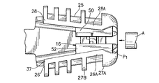
図6を参照して、この発明の他の実施例及びコネクタに装着された導体にしたがって終端コネクタ110の平面図が示される。この実施例において、終端コネクタ110は、ウェッジ端区分124及びそれによる細長い操作部材122を有する。操作部材は、ユーザーが終端コネクタを操作し、及び又は構造物又は操作装置に終端コネクタを取付けられるようにするものである。代わりの実施例において、ウェッジ区分から延びる操作部材が、あらゆる適切な形状を有することができる。操作部材122は、例えば、部材の端132における少なくとも1つの取付け穴123を有する細長いバー又は取付け柱であるような図6に示される。ウェッジ部材124は、前述し、図1−4に示されたコネクタ10のウェッジ区分22、24とほぼ同一である。同一の特徴は、同一の符号を有する。ウェッジ区分124は、その中にウェッジ116を保持する。ウェッジ116は、ウェッジ部材50、52(図3A−3B参照)について説明したのと同一の方法で組合される2つのウェッジ部材150、152を有する。ウェッジ部材150、152は、自動的に、ウェッジ区分124内に保持されるスプリング18と同一のスプリング(図示せず)によってセットされる。ウェッジ区分の外方端134は、丸い外部表面103及びラッパをなす内部表面104を有する。側壁126、128は、連続した隣接するスチフナ間の連続して比較的に小間隔によって分離されたスチフナ127A−127Eを有する。したがって、ウェッジ区分124は、異なる位置、又はウェッジ区分のウェッジ16に対応する異なる強度及び剛性を有する部分を具備する。   Referring to FIG. 6, a plan view of termination connector 110 is shown according to another embodiment of the present invention and conductors attached to the connector. In this embodiment, end connector 110 has a wedge end section 124 and an elongated operating member 122 thereby. The operating member allows the user to operate the end connector and / or attach the end connector to a structure or operating device. In alternative embodiments, the operating member extending from the wedge section can have any suitable shape. The operating member 122 is shown in FIG. 6 as being, for example, an elongated bar or mounting post having at least one mounting hole 123 at the end 132 of the member. The wedge member 124 is substantially the same as the wedge sections 22, 24 of the connector 10 described above and shown in FIGS. 1-4. The same features have the same reference numbers. The wedge section 124 holds the wedge 116 therein. The wedge 116 has two wedge members 150, 152 that are combined in the same manner as described for the wedge members 50, 52 (see FIGS. 3A-3B). The wedge members 150, 152 are automatically set by the same spring (not shown) as the spring 18 held in the wedge section 124. The outer end 134 of the wedge section has a rounded outer surface 103 and a trumpeted inner surface 104. Sidewalls 126, 128 have stiffeners 127A-127E separated by successive relatively small spaces between successive adjacent stiffeners. Thus, the wedge section 124 includes portions having different strengths and stiffnesses corresponding to the wedges 16 at different locations or wedge sections.

前記したように、既知の頭上の電力コネクタの構造は、コネクタとともに使用される最大の寸法の導体を接続するときには、最大の接続負荷(例えばコネクタシェルに対してウェッジから押し開ける負荷のような)を支持することができる。したがって、コネクタの構造はこのように寸法どりされる。しかしながら、従来の頭上コネクタにおいて、コネクタ構造、特にはコネクタシェルは、ほぼ一定であり、又は一般的であり、コネクタの特別な部分に与えられる接続負荷の大きさに無頓着なコネクタの長さのためにユニット長さ当りのほぼ同一の強度及び剛性を有する。このことは、従来のコネクタの対応する重量及び又コストの増大とともに、従来の頭上コネクタに使用される過剰な材料に結果する。従来の頭上電力コネクタの過剰な重量の影響はそれらの名前で表示されるように、頭上電力コネクタは通常頭上で装着されるか、又は導体とともに頭上に引き上げられることにおいて、複雑である。ここに、従来のコネクタの過剰な重量は、装着のためにユーザーから過剰な努力を要求している。コネクタ10、110は、コネクタフレームが、それが望まれる領域において特別仕立てで、適切な剛性及び強度を提供することにおいて、従来のコネクタの問題を克服する。これは、より軽い、かつ電力線のための装着コストを減少する自動コネクタを使用することをより容易にする結果をもたらす。   As noted above, known overhead power connector constructions have a maximum connection load (such as a load that pushes away from the wedge against the connector shell) when connecting the largest dimension conductors used with the connector. Can be supported. The connector structure is thus dimensioned in this way. However, in conventional overhead connectors, the connector structure, and in particular the connector shell, is generally constant or common, due to the length of the connector that is inconsequential to the magnitude of the connection load applied to a particular part of the connector. Have almost the same strength and rigidity per unit length. This results in excess material used in conventional overhead connectors, along with the corresponding weight and / or cost increase of conventional connectors. As the effects of the excessive weight of conventional overhead power connectors are indicated by their names, overhead power connectors are usually complex in that they are worn overhead or lifted overhead with conductors. Here, the excessive weight of conventional connectors requires excessive effort from the user for installation. Connectors 10, 110 overcome the problems of conventional connectors in that the connector frame is tailored in the area where it is desired and provides adequate rigidity and strength. This results in making it easier to use an automatic connector that is lighter and reduces the mounting costs for the power line.

さらに、通常は頭上実用線を支持して、又は地中導管において使用される、ポールに対する導体の装着は、それが装着位置に引張られるので、導体を支持しガイドするために使用される電線張り滑車装置(図5に示されるように)を使用することができる。コネクタの装着の間、例えば終端コネクタのようなコネクタは、引張りの間、導体の端部を掴むために使用することができる。従来の頭上コネクタは、普通、導体が引張られたときに電線張り滑車装置に対してジャムする傾向を有する、尖っていない、又は平坦な端部を有する。多大な努力が、従来のコネクタを除去し、それと電線張り滑車装置を介して導体とをひっぱるのに用いられる。従来のコネクタに対する鋭い対比において、自動コネクタ10、110は、前述したように電線張り滑車装置を介してコネクタの導入及び通過を容易にする、丸く、かつ輪郭線の外部及び内部表面を有する。   In addition, the mounting of the conductor to the pole, usually used to support overhead overhead lines or in underground conduits, is the wire tension used to support and guide the conductor as it is pulled to the mounting position. A pulley device (as shown in FIG. 5) can be used. During connector mounting, a connector, such as a terminal connector, can be used to grip the end of the conductor during pulling. Conventional overhead connectors usually have a non-pointed or flat end that tends to jam with respect to the wire pulley device when the conductor is pulled. A great deal of effort is used to remove the conventional connector and pull the conductor through it and the wire tensioning pulley device. In sharp contrast to conventional connectors, the automatic connectors 10, 110 have rounded and contoured outer and inner surfaces that facilitate the introduction and passage of the connectors through the wire pulley system as described above.

さらになお、自動頭上電力コネクタはコネクタ内にウェッジを自動的に係合するという自動性能の故に、望ましい。しかしながら、自動的頭上コネクタは、ラッチ又はロックを提供して、導体がコネクタ内に配置されるようにスプリング偏倚に対して開放又は解除位置にウェッジを保持する。従来の頭上コネクタは、ウェッジ及びコネクタシェルの両方においてキャッチファセットの機械加工、又はシェルにおけるウェッジをラッチするために使用される分離したラッチ部分を製造することを必要とする多数のラッチング装置を使用する。従来のコネクタのシェルにおけるラッチングファセット、又はエッジを機械加工することは、シェルの複雑な幾何学(例えば、シェルは、固定して位置し、保持するためにより困難である)の故に、時間の浪費である。シェルにおける位置にウェッジを保持するだけのことに専用の分離したラッチ部分を製造すること は、又費用がかかり、非効率である。この発明のコネクタ10、110においては、ラッチ性能は、ウェッジ部材に含まれている。このことは、従来のコネクタと対比してラッチの製造を単純化する。さらに、コネクタ10、110のラッチ性能は、ユーザーによって単に押すだけ(1タブを)でラッチを係合し、それから押してラッチを解放することで難なく容易に操作される。   Still further, an automatic overhead power connector is desirable because of the automatic performance of automatically engaging a wedge within the connector. However, the automatic overhead connector provides a latch or lock to hold the wedge in the open or released position against the spring bias so that the conductor is placed in the connector. Conventional overhead connectors use a number of latching devices that require machining of the catch facets in both the wedge and the connector shell, or manufacturing a separate latch portion that is used to latch the wedge in the shell. . Machining latching facets, or edges, in conventional connector shells is time consuming due to the complex geometry of the shell (eg, the shell is more difficult to position and hold in place) It is. It is also expensive and inefficient to produce a separate latch portion that is dedicated solely to holding the wedge in position in the shell. In the connectors 10 and 110 of the present invention, the latching performance is included in the wedge member. This simplifies the manufacture of the latch compared to conventional connectors. Further, the latching performance of the connectors 10, 110 is easily manipulated without difficulty by engaging the latch by simply pushing (one tab) by the user and then pushing to release the latch.

これまでの説明は、単にこの発明の例証であるに過ぎないことを理解すべきである。多様な変更と修正が、この発明から逸脱しないで当業者によって案出され得る。したがって、この発明は、あらゆる選択、修正及び付属の請求項の範囲内における変更を包含することを意図している。   It should be understood that the foregoing description is merely illustrative of the invention. Various changes and modifications can be devised by those skilled in the art without departing from the invention. Accordingly, the present invention is intended to embrace all such selections, modifications and variations that fall within the scope of the appended claims.

一実施例によるこの発明の特徴を具体化した電気ウェッジコネクタと2本の導体との分解斜視図。1 is an exploded perspective view of an electrical wedge connector and two conductors embodying features of the present invention according to one embodiment. FIG. 図1におけるウェッジコネクタのフレームの平面図。The top view of the frame of the wedge connector in FIG. 図1におけるウェッジコネクタの対向するウェッジ部材の底部斜視図。The bottom part perspective view of the wedge member which the wedge connector in FIG. 同じく、図1におけるウェッジコネクタの対向するウェッジ部材の底部斜視図。Similarly, the bottom part perspective view of the wedge member which the wedge connector in FIG. 図1におけるウェッジコネクタにおける1つの位置における対向するウェッジ部材を示す部分平面図。The fragmentary top view which shows the wedge member which opposes in one position in the wedge connector in FIG. 同じく、図1におけるウェッジコネクタにおける他の位置における対向するウェッジ部材を示す部分平面図。Similarly, the fragmentary top view which shows the wedge member which opposes in the other position in the wedge connector in FIG. 同じく、図1におけるウェッジコネクタにおけるさらに他の位置における対向するウェッジ部材を示す部分平面図。Similarly, the fragmentary top view which shows the wedge member which opposes in the other position in the wedge connector in FIG. 図1におけるウェッジコネクタとともに使用される従来の電線張り滑車装置の斜視図。The perspective view of the conventional electric wire tension pulley apparatus used with the wedge connector in FIG. 前記電線張り滑車装置に設置された図1におけるウェッジコネクタの部分正面図。The partial front view of the wedge connector in FIG. 1 installed in the said electric wire tension pulley apparatus. この発明の他の実施例によるウェッジコネクタの斜視図。The perspective view of the wedge connector by the other Example of this invention.

Claims (30)

その中にウェッジ受入通路を定めるシェルと、前記ウェッジ受入通路に挿入されたときにこのシェルに対してくさび止めする形状にされたウェッジであって、このウェッジは、それが前記シェル内にくさび止めされるときにシェル内に導体を受入れてしっかりと保持するための導体受入チャネルをその中に有するウェッジとを有してなり、前記シェルは、前記ウェッジが前記シェルの第1部分にくさび止めされるときにそのウェッジに第1のクランプ力を生じる第1の弾性剛性を有する第1の部分を有し、さらに前記ウェッジが前記シェルの第2部分にくさび止めされるときにそのウェッジに第2のクランプ力を生じる第2の弾性剛性を有する第2の部分を有する電気ウェッジコネクタ。 A shell defining a wedge receiving passage therein and a wedge shaped to wedge against the shell when inserted into the wedge receiving passage, wherein the wedge is wedged within the shell And a wedge having a conductor receiving channel therein for receiving and securely holding the conductor within the shell, the shell being wedged to the first portion of the shell. A first portion having a first elastic stiffness that produces a first clamping force on the wedge when the wedge is wedged to the second portion of the shell. An electrical wedge connector having a second portion having a second elastic stiffness that produces a clamping force of. 前記シェルは、スプライスコネクタシェルであり、デッドエンドコネクタシェルであり、又はリダクションコネクタシェルである前記請求項1記載のコネクタ。 The connector according to claim 1, wherein the shell is a splice connector shell, a dead-end connector shell, or a reduction connector shell. 前記ウェッジは、前記対向するウェッジ部材間に前記導体を保持するための導体受入チャネルを定める1対の対向するウェッジ部材を有する前記請求項1記載のコネクタ。 The connector of claim 1, wherein the wedge includes a pair of opposing wedge members defining a conductor receiving channel for holding the conductor between the opposing wedge members. 前記対向するウェッジ部材は、スプリング負荷して、前記シェル内に前記ウェッジ部材を偏倚する前記請求項3記載のコネクタ。 4. The connector of claim 3, wherein the opposing wedge members are spring loaded to bias the wedge member within the shell. 前記ウェッジは、前記導体が前記ウェッジ内に第1の断面部を保持させたときに前記シェルの前記第1の部分に位置され、さらに前記ウェッジは、前記導体が前記ウェッジ内に第2の断面部を保持させたときに前記シェルの前記第2の部分に位置される前記請求項1記載のコネクタ。 The wedge is positioned in the first portion of the shell when the conductor holds a first cross section in the wedge, and the wedge is further in a second cross section where the conductor is in the wedge. The connector according to claim 1, wherein the connector is positioned in the second portion of the shell when the portion is held. 前記第2の断面部は、前記第1の断面部よりも大きく、前記第2の弾性剛性は前記第1の弾性剛性よりも高い前記請求項5記載のコネクタ。 The connector according to claim 5, wherein the second cross-sectional portion is larger than the first cross-sectional portion, and the second elastic rigidity is higher than the first elastic rigidity. 前記シェルには、対向壁から外方にデプするスチフナを有し、前記シェルの第2区分は、前記第1の部分より前記対向する壁に沿って整列されたより大きなスチフナを有する前記請求項1記載のコネクタ。 The shell includes a stiffener that is recessed outwardly from an opposing wall, and the second section of the shell includes a larger stiffener aligned along the opposing wall than the first portion. The connector described. 前記スチフナは、隣接するスチフナが、連続したシェルの一端からシェルの他端に減少するように、前記対向する壁に沿って広がっている前記請求項7記載のコネクタ。 8. The connector of claim 7, wherein the stiffener extends along the opposing walls such that adjacent stiffeners decrease from one end of the continuous shell to the other end of the shell. 前記シェルは、前記シェルの一端に向かって狭い傾斜形状を有する前記請求項8記載のコネクタ。 The connector according to claim 8, wherein the shell has a narrow inclined shape toward one end of the shell. 前記シェルは、前記ウェッジによってコネクタ内に保持された導体が電線張り滑車装置を越えて引かれたときにその電線張り滑車装置内にコネクタをガイドするために丸い外部ガイド面を有する一端を具備する前記請求項1記載のコネクタ。 The shell includes one end having a round external guide surface to guide the connector into the wire tensioning pulley device when a conductor held in the connector by the wedge is pulled over the wire tension pulley device. The connector according to claim 1. 前記ウェッジは、中間に前記導体を保持するためにされた1対の対向するウェッジ部材と、前記ウェッジがシェル内にくさび止めするときに、離隔絶縁器でウェッジ部材の対向する一方を保持するために離隔絶縁器タブを有する対向するウェッジ部材の少なくとも1つとを有する前記請求項1記載のコネクタ。 The wedge holds a pair of opposing wedge members arranged to hold the conductor in the middle, and a opposing insulator with a separate insulator when the wedge wedges into the shell. The connector of claim 1, further comprising: at least one opposing wedge member having a separate insulator tab. 前記離隔絶縁器のタブが、前記ウェッジが前記シェル内にくさび止めされるときに2つの異なる離隔絶縁器の距離に前記対向するウェッジ部材を保持するように配置された2つの支持表面を有する前記請求項11記載のコネクタ。 The tab of the isolation insulator has two support surfaces arranged to hold the opposing wedge members at a distance of two different isolation insulators when the wedge is wedged into the shell. The connector according to claim 11. 中間にウェッジ受入通路を定める対向する壁を有する少なくとも1つのシェル区分を有するフレームと、前記ウェッジが前記ウェッジ受入通路に挿入されるときに前記シェルの対向する壁に対してくさび止めする形状にされたウェッジであって、このウェッジは、ウェッジが前記シェル内にくさび止めされるときに前記シェル内に導体を受入れてしっかりと保持するためにその中に導体受入チャネルを有するウェッジとを具備してなり、前記対向する壁は、それからそれによって定まるスチフナは、隣接するそのスチフナ間に異なる空間を有する対向壁の少なくとも一方に沿って供給される電気ウェッジコネクタ。 A frame having at least one shell section having opposing walls defining a wedge receiving passage in the middle, and shaped to wedge against the opposing walls of the shell when the wedge is inserted into the wedge receiving passage. A wedge having a conductor receiving channel therein for receiving and securely holding the conductor in the shell when the wedge is wedged in the shell. An electrical wedge connector, wherein the opposing walls, then the stiffeners defined thereby are fed along at least one of the opposing walls having a different space between the adjacent stiffeners. 前記スチフナは、対向する壁に配置されて、前記ウェッジが前記ウェッジ受入通路にくさび止めされるときに、前記対向する壁に対してウェッジによって供給されたくさび止め力を抑制する前記請求項13記載のコネクタ。 14. The stiffener is disposed on an opposing wall and suppresses the wedge stopping force supplied by the wedge to the opposing wall when the wedge is wedged in the wedge receiving passage. Connector. 前記フレームは、少なくとも1つのシェル区分からのフレームの対向端に他のシェル区分を有する前記請求項13記載のコネクタ。 14. The connector of claim 13, wherein the frame has another shell section at the opposite end of the frame from at least one shell section. 両方の対向壁の前記スチフナは、隣接するスチフナ間の異なる空間を有する両方の対向壁に沿って分配される前記請求項13記載のコネクタ。 14. The connector of claim 13, wherein the stiffeners on both opposing walls are distributed along both opposing walls having different spaces between adjacent stiffeners. 連続する隣接するスチフナ間の空間は、前記シェル区分の第1端から第2端に順次減少する前記請求項13記載のコネクタ。 14. A connector according to claim 13, wherein the space between successive adjacent stiffeners decreases sequentially from a first end to a second end of the shell section. 前記ウェッジは、第2端から第1端に前記シェル区分に挿入される前記請求項17記載のコネクタ。 The connector of claim 17, wherein the wedge is inserted into the shell section from a second end to a first end. 前記シェル区分の第1端における隣接するスチフナは、第1の内部スチフナ空間を有し、前記シェルの第2端における隣接するスチフナは前記第1の内部スチフナよりも第2の内部スチフナ空間を有する異なる空間を有する前記請求項13記載のコネクタ。 The adjacent stiffener at the first end of the shell section has a first internal stiffener space, and the adjacent stiffener at the second end of the shell has a second internal stiffener space rather than the first internal stiffener. The connector according to claim 13, wherein the connector has different spaces. その中にウェッジ受入通路を有するシェルと、このシェル内に導体を収容するための前記ウェッジ受入通路内にくさび止めするようにされたウェッジとを有してなり、前記シェルは、そのシェル内に収容された導体が前記電線張り滑車装置を越えて引かれるときに、この電線張り滑車装置内にウェッジコネクタをガイドするための丸い外部ガイド面を有する第1端を具備する電気ウェッジコネクタ。 A shell having a wedge receiving passage therein, and a wedge wedged in the wedge receiving passage for receiving a conductor in the shell, the shell being in the shell An electrical wedge connector comprising a first end having a rounded outer guide surface for guiding a wedge connector within the wire tensioning pulley device when the contained conductor is pulled over the wire tension pulley device. 前記丸いガイド面は、前記導体が前記電線張り滑車装置を越えて引かれ、前記丸い外部ガイド面が、前記電線張り滑車装置が、前記電線張り滑車装置における溝と接触するときに、丸い外部ガイド面及び溝は協働して前記電線張り滑車装置内に前記シェルの第1端の導入を実質的に妨げないことができる前記請求項20記載のコネクタ。 The round guide surface is drawn when the conductor is drawn beyond the wire tension pulley device, and the round outer guide surface is rounded when the wire tension pulley device contacts a groove in the wire tension pulley device. 21. The connector of claim 20, wherein the face and groove cooperate to substantially not impede introduction of the first end of the shell into the wire tensioning pulley apparatus. ウェッジ受入チャネルを有するシェルを具備するフレームと、シェル内に導体をクランプするためのウェッジ受入チャンネル内に位置された1対の対向するウェッジ部材であって、前記1対の対向ウェッジ部材の少なくとも1つのウェッジ部材が離隔絶縁器で前記1対の対向するウェッジ部材と接触して保持する離隔絶縁器の突出部を有するウェッジ部材を有してなり、前記離隔絶縁器突出部は、前記対向するウェッジ部材と接触し少なくとも1つのウェッジ部材からの2つの異なる離隔絶縁器における前記対向するウェッジ部材を保持するための2つの停止表面を有する電気コネクタ。 A frame comprising a shell having a wedge receiving channel; and a pair of opposing wedge members positioned in the wedge receiving channel for clamping a conductor in the shell, wherein at least one of the pair of opposing wedge members One wedge member comprises a wedge member having a protrusion of a separation insulator that is held in contact with the pair of opposed wedge members by a separation insulator, and the separation insulator protrusion is formed of the opposite wedge. An electrical connector having two stop surfaces for contacting said member and holding said opposing wedge members in two different spaced insulators from at least one wedge member. 前記2つの停止表面の第1がその対向するウェッジ部材と接触するときに、前記対向するウェッジ部材は、第1の離隔絶縁器において保持され、さらに前記2つの停止表面の第2がその対向するウェッジ部材と接触するときに、前記対向するウェッジ部材は、第2の離隔絶縁器において保持される前記請求項22記載のコネクタ。 When the first of the two stop surfaces contacts the opposing wedge member, the opposing wedge member is retained in a first isolation insulator, and the second of the two stop surfaces is opposite. 23. The connector of claim 22, wherein when facing a wedge member, the opposing wedge member is retained in a second isolation insulator. 前記対向するウェッジ部材は、少なくとも1つのウェッジ部材の離隔絶縁器の突出部に対向して延びる他の離隔絶縁器の突出部を有しており、前記他の離隔絶縁器の突出部は少なくとも1つのウェッジ部材と接触する他の停止表面を有する前記請求項22記載のコネクタ。 The opposing wedge member has a protrusion of another isolation insulator extending opposite the protrusion of the isolation insulator of at least one wedge member, and the protrusion of the other isolation insulator is at least 1 24. The connector of claim 22, having another stop surface that contacts one wedge member. 前記離隔絶縁器の突出部は、前記対向するウェッジ部材に向かって少なくとも1つのウェッジ部材から横方向に延びるタブである前記請求項22記載のコネクタ。 23. The connector of claim 22, wherein the protrusion of the isolation insulator is a tab that extends laterally from at least one wedge member toward the opposing wedge member. 前記タブは、その中に形成された段部であり、その段部の横方向エッジは、離隔絶縁器の突出部の前記2つの停止表面を形成する前記請求項25記載のコネクタ。 26. The connector of claim 25, wherein the tab is a step formed therein, and a lateral edge of the step forms the two stop surfaces of the protrusion of the isolation insulator. 前記対向するウェッジ部材は、前記少なくとも1つのウェッジ部材のタブに対向して延びる他のタブを有し、さらに前記他のタブは、前記タブにおける段部に対して相補的に他の段部を有する前記請求項26記載のコネクタ。 The opposing wedge members have other tabs extending opposite the tabs of the at least one wedge member, and the other tabs have other steps complementary to the steps in the tabs. 27. The connector of claim 26, comprising: 前記対向するウェッジ部材は、前記シェル内にウェッジ部材を偏位するように負荷されたスプリングであり、さらに離隔絶縁器の突出部は、スプリング負荷偏倚に対して2つの異なる離隔絶縁器において、対向するウェッジ部材を保持する前記請求項22記載のコネクタ。 The opposing wedge member is a spring loaded to deflect the wedge member within the shell, and the protrusion of the isolation insulator is opposed to the spring load bias in two different isolation insulators. The connector according to claim 22, wherein the connector holds a wedge member. 前記2つの停止表面は、対向するウェッジ部材における段部と係合し、初期の離隔絶縁器における対向するウェッジ部材を保持し、前記対向するウェッジ部材間の前記初期の離隔絶縁器におけるシェルに対してくさび止めできる前記請求項28記載のコネクタ。 The two stop surfaces engage the step in the opposing wedge member, hold the opposing wedge member in the initial isolation insulator, and against the shell in the initial isolation insulator between the opposing wedge members 29. The connector of claim 28, wherein the connector can be wedge-proofed. 前記第1停止表面が前記段部から離脱されるときに前記スプリング負荷は2つの停止表面の第2の停止表面が対向するウェッジ部材と接触するまで前記シェル内に対向するウェッジ部材を移動する前記請求項29記載のコネクタ。 When the first stop surface is detached from the step, the spring load moves the opposing wedge member in the shell until the second stop surface of the two stop surfaces contacts the opposing wedge member. 30. The connector according to claim 29.
JP2004512236A 2002-06-06 2003-06-05 Automatic electrical wedge connector Pending JP2005536009A (en)

Applications Claiming Priority (2)

Application Number Priority Date Filing Date Title
US10/165,107 US6796854B2 (en) 2002-06-06 2002-06-06 Automatic electrical wedge connector
PCT/US2003/018022 WO2003105280A1 (en) 2002-06-06 2003-06-05 Automatic electrical wedge connector

Related Child Applications (1)

Application Number Title Priority Date Filing Date
JP2006156365A Division JP4129026B2 (en) 2002-06-06 2006-06-05 Automatic electrical wedge connector

Publications (2)

Publication Number Publication Date
JP2005536009A true JP2005536009A (en) 2005-11-24
JP2005536009A5 JP2005536009A5 (en) 2006-07-20

Family

ID=29710363

Family Applications (2)

Application Number Title Priority Date Filing Date
JP2004512236A Pending JP2005536009A (en) 2002-06-06 2003-06-05 Automatic electrical wedge connector
JP2006156365A Expired - Fee Related JP4129026B2 (en) 2002-06-06 2006-06-05 Automatic electrical wedge connector

Family Applications After (1)

Application Number Title Priority Date Filing Date
JP2006156365A Expired - Fee Related JP4129026B2 (en) 2002-06-06 2006-06-05 Automatic electrical wedge connector

Country Status (8)

Country Link
US (2) US6796854B2 (en)
JP (2) JP2005536009A (en)
CN (2) CN100341200C (en)
AU (1) AU2003238949A1 (en)
BR (1) BR0311532A (en)
CA (1) CA2485345A1 (en)
MX (1) MXPA04011305A (en)
WO (1) WO2003105280A1 (en)

Families Citing this family (23)

* Cited by examiner, † Cited by third party
Publication number Priority date Publication date Assignee Title
JP4094529B2 (en) * 2003-11-10 2008-06-04 本田技研工業株式会社 Ignition device
US7070462B2 (en) * 2003-12-02 2006-07-04 Fci Americas Technology, Inc. Electrical connector with expandable tubular clamping sections
GB2419916A (en) * 2004-11-04 2006-05-10 Clamcleats Ltd Cleat assembly including a V-shaped groove having ridged grip walls wherein entry of an elongate member to the grip walls is controlled by a gate member(s)
JP4950635B2 (en) 2006-11-24 2012-06-13 株式会社ニフコ Retraction mechanism
US7799996B2 (en) * 2008-05-30 2010-09-21 Hubbell Incorporated Corrosion resistant automatic splice
US8984722B2 (en) 2011-02-23 2015-03-24 Hubbell Incorporated Wedge dead end clamp assembly
CN102515038B (en) * 2012-01-12 2014-06-18 巨力索具股份有限公司 Manufacturing method of prestress steel wire rope row
US9059522B2 (en) * 2012-12-13 2015-06-16 Tyco Electronics Corporation Wedge connector assemblies and methods for connecting electrical conductors using same
US9054445B2 (en) 2013-03-14 2015-06-09 Tyco Electronics Corporation Electrical connectors and methods for using same
DE102013110477B4 (en) * 2013-09-23 2021-11-04 Phoenix Contact Gmbh & Co. Kg Feed-through terminal and electrical construction equipment
CN105932443A (en) * 2016-04-22 2016-09-07 国家电网公司 Lead connector
US10862289B2 (en) 2016-11-03 2020-12-08 Hubbell Incorporated Flexible cable splice
US10680353B2 (en) * 2017-05-09 2020-06-09 TE Connectivity Services Gmbh Wedge connector assemblies and methods and connections including same
US10594054B2 (en) 2017-05-09 2020-03-17 Tyco Electronics Canada Ulc Wedge connector assemblies and methods and connections including same
US10957994B2 (en) 2017-05-26 2021-03-23 Tyco Electronics Canada Ulc Wedge connector assemblies and methods and connections including same
CN108808606B (en) * 2018-06-06 2021-07-16 昆明理工大学 Automatic fastener device of fastening
CN109038436B (en) * 2018-08-17 2020-09-29 国网安徽省电力有限公司电力科学研究院 Backup protection system for circuit broken card
US10700449B2 (en) * 2018-09-28 2020-06-30 Abb Schweiz Ag Split wedge connector
US11287595B2 (en) 2018-12-04 2022-03-29 Hubbell Incorporated Fiber optic dead-end cable clamp with central actuator
US11329401B2 (en) 2019-02-20 2022-05-10 Tyco Electronics Canada Ulc Electrical connection bails and stirrup systems and methods including same
US11967805B2 (en) 2019-09-24 2024-04-23 Hubbell Incorporated Formed wire inlay tool
CN113054452B (en) * 2020-12-29 2023-04-11 贵州电网有限责任公司 Coaxial round rod conductor wedge self-locking device and construction method thereof
US11591048B1 (en) * 2021-02-11 2023-02-28 Hotwire Development, Llc Block and tackle assembly for bladder anchor

Family Cites Families (14)

* Cited by examiner, † Cited by third party
Publication number Priority date Publication date Assignee Title
US1801277A (en) * 1926-05-22 1931-04-21 Will G Kelley Means for connecting electrical conductors
US2078051A (en) * 1935-04-11 1937-04-20 Electroline Corp Connecter for stranded cable
US2799721A (en) * 1953-01-09 1957-07-16 Amp Inc Connector
US4407471A (en) 1980-12-17 1983-10-04 Dr. Franz & Rutenbeck Clamping device for self-supporting electric cables
US4415222A (en) * 1981-01-19 1983-11-15 Mario Polidori Electrical connector
US4428100A (en) 1982-04-16 1984-01-31 Square D Company Flip top automatic deadend
FR2606560B1 (en) 1986-11-06 1989-03-03 Lienart Jean Pierre ANCHORING CLIP FOR INSULATED ELECTRICAL CONDUCTOR EQUIPPED WITH AN ALSO INSULATED CARRIER CABLE
US4845814A (en) * 1987-04-13 1989-07-11 Crosby Group, Inc. Wedge socket
US5240441A (en) * 1992-09-04 1993-08-31 The Whitaker Corporation Electrical wire connector
FR2718300B1 (en) 1994-03-29 1996-12-13 Malico Sa Anchoring clamp for a cable.
US5539961A (en) 1994-10-18 1996-07-30 Fargo Mfg. Company Inc. Spring-loaded wedge dead end
US6076236A (en) 1999-04-02 2000-06-20 Maclean-Fogg Company Top opening cable connector
US6146216A (en) * 1999-04-12 2000-11-14 Timsit; Roland Sion Electrical wire connector
US6547481B2 (en) * 2001-02-08 2003-04-15 Hubbell Incorporated Spring-loaded wedge dead end connector having elements for coupling together and preventing removal of conductor-gripping jaws

Also Published As

Publication number Publication date
US6796854B2 (en) 2004-09-28
US20040203294A1 (en) 2004-10-14
WO2003105280A1 (en) 2003-12-18
JP2006304597A (en) 2006-11-02
CA2485345A1 (en) 2003-12-18
AU2003238949A1 (en) 2003-12-22
CN1659744A (en) 2005-08-24
MXPA04011305A (en) 2005-02-14
CN100492767C (en) 2009-05-27
US20030228807A1 (en) 2003-12-11
JP4129026B2 (en) 2008-07-30
BR0311532A (en) 2005-04-12
CN100341200C (en) 2007-10-03
CN101047284A (en) 2007-10-03

Similar Documents

Publication Publication Date Title
JP4129026B2 (en) Automatic electrical wedge connector
US5692930A (en) Electrical distribution system connector
US4416503A (en) Gripping or locating devices
JP3182086B2 (en) Wire guide device
KR101928460B1 (en) Wedge dead end clamp assembly
US5539961A (en) Spring-loaded wedge dead end
US20100279540A1 (en) Wire etc, connectors
JPH01154471A (en) Electrical connector
US4130330A (en) Electrical connector strain relief and cover retention system
JPS648901B2 (en)
US7234669B2 (en) Clamp
US2196383A (en) Wire connector
US20020119710A1 (en) Electrical connector having frame and slidable members
US20020106239A1 (en) Spring-loaded wedge dead end connector having elements for coupling together and preventing removal of conductor-gripping jaws
KR100760811B1 (en) Connection assembly of cable conductor using wedge and the connection method
US20210257764A1 (en) Electrical Connector
JPS61191223A (en) Lead-in clamp
KR101098156B1 (en) Wire retention connector system
US6283804B1 (en) Cable connector for electrical connections
US11063416B2 (en) Clamp for a wire of an overhead line and method for tightening a wire of an overhead line
WO2000001035A2 (en) Electrical cable connector and insert therefor
US5928039A (en) Electrical wire connector
KR100550958B1 (en) Scrolled jaws and the power cable maintained device with those
US20060246767A1 (en) Wire-terminal element
US5752861A (en) Electrical wire connector with improved wedge

Legal Events

Date Code Title Description
A521 Written amendment

Free format text: JAPANESE INTERMEDIATE CODE: A523

Effective date: 20060605

A621 Written request for application examination

Free format text: JAPANESE INTERMEDIATE CODE: A621

Effective date: 20060605

A131 Notification of reasons for refusal

Free format text: JAPANESE INTERMEDIATE CODE: A131

Effective date: 20080715

A02 Decision of refusal

Free format text: JAPANESE INTERMEDIATE CODE: A02

Effective date: 20081209