JP2005535913A - Electrophoretic display device having liquid crystal suspension medium and method for manufacturing the same - Google Patents
Electrophoretic display device having liquid crystal suspension medium and method for manufacturing the same Download PDFInfo
- Publication number
- JP2005535913A JP2005535913A JP2004527061A JP2004527061A JP2005535913A JP 2005535913 A JP2005535913 A JP 2005535913A JP 2004527061 A JP2004527061 A JP 2004527061A JP 2004527061 A JP2004527061 A JP 2004527061A JP 2005535913 A JP2005535913 A JP 2005535913A
- Authority
- JP
- Japan
- Prior art keywords
- liquid crystal
- solvent
- display
- cell
- particles
- Prior art date
- Legal status (The legal status is an assumption and is not a legal conclusion. Google has not performed a legal analysis and makes no representation as to the accuracy of the status listed.)
- Ceased
Links
Images


Classifications
-
- B—PERFORMING OPERATIONS; TRANSPORTING
- B01—PHYSICAL OR CHEMICAL PROCESSES OR APPARATUS IN GENERAL
- B01J—CHEMICAL OR PHYSICAL PROCESSES, e.g. CATALYSIS OR COLLOID CHEMISTRY; THEIR RELEVANT APPARATUS
- B01J13/00—Colloid chemistry, e.g. the production of colloidal materials or their solutions, not otherwise provided for; Making microcapsules or microballoons
- B01J13/02—Making microcapsules or microballoons
- B01J13/20—After-treatment of capsule walls, e.g. hardening
- B01J13/22—Coating
-
- B—PERFORMING OPERATIONS; TRANSPORTING
- B01—PHYSICAL OR CHEMICAL PROCESSES OR APPARATUS IN GENERAL
- B01J—CHEMICAL OR PHYSICAL PROCESSES, e.g. CATALYSIS OR COLLOID CHEMISTRY; THEIR RELEVANT APPARATUS
- B01J13/00—Colloid chemistry, e.g. the production of colloidal materials or their solutions, not otherwise provided for; Making microcapsules or microballoons
- B01J13/02—Making microcapsules or microballoons
- B01J13/06—Making microcapsules or microballoons by phase separation
- B01J13/10—Complex coacervation, i.e. interaction of oppositely charged particles
-
- G—PHYSICS
- G02—OPTICS
- G02F—OPTICAL DEVICES OR ARRANGEMENTS FOR THE CONTROL OF LIGHT BY MODIFICATION OF THE OPTICAL PROPERTIES OF THE MEDIA OF THE ELEMENTS INVOLVED THEREIN; NON-LINEAR OPTICS; FREQUENCY-CHANGING OF LIGHT; OPTICAL LOGIC ELEMENTS; OPTICAL ANALOGUE/DIGITAL CONVERTERS
- G02F1/00—Devices or arrangements for the control of the intensity, colour, phase, polarisation or direction of light arriving from an independent light source, e.g. switching, gating or modulating; Non-linear optics
- G02F1/01—Devices or arrangements for the control of the intensity, colour, phase, polarisation or direction of light arriving from an independent light source, e.g. switching, gating or modulating; Non-linear optics for the control of the intensity, phase, polarisation or colour
- G02F1/165—Devices or arrangements for the control of the intensity, colour, phase, polarisation or direction of light arriving from an independent light source, e.g. switching, gating or modulating; Non-linear optics for the control of the intensity, phase, polarisation or colour based on translational movement of particles in a fluid under the influence of an applied field
- G02F1/166—Devices or arrangements for the control of the intensity, colour, phase, polarisation or direction of light arriving from an independent light source, e.g. switching, gating or modulating; Non-linear optics for the control of the intensity, phase, polarisation or colour based on translational movement of particles in a fluid under the influence of an applied field characterised by the electro-optical or magneto-optical effect
- G02F1/167—Devices or arrangements for the control of the intensity, colour, phase, polarisation or direction of light arriving from an independent light source, e.g. switching, gating or modulating; Non-linear optics for the control of the intensity, phase, polarisation or colour based on translational movement of particles in a fluid under the influence of an applied field characterised by the electro-optical or magneto-optical effect by electrophoresis
-
- G—PHYSICS
- G02—OPTICS
- G02F—OPTICAL DEVICES OR ARRANGEMENTS FOR THE CONTROL OF LIGHT BY MODIFICATION OF THE OPTICAL PROPERTIES OF THE MEDIA OF THE ELEMENTS INVOLVED THEREIN; NON-LINEAR OPTICS; FREQUENCY-CHANGING OF LIGHT; OPTICAL LOGIC ELEMENTS; OPTICAL ANALOGUE/DIGITAL CONVERTERS
- G02F1/00—Devices or arrangements for the control of the intensity, colour, phase, polarisation or direction of light arriving from an independent light source, e.g. switching, gating or modulating; Non-linear optics
- G02F1/01—Devices or arrangements for the control of the intensity, colour, phase, polarisation or direction of light arriving from an independent light source, e.g. switching, gating or modulating; Non-linear optics for the control of the intensity, phase, polarisation or colour
- G02F1/13—Devices or arrangements for the control of the intensity, colour, phase, polarisation or direction of light arriving from an independent light source, e.g. switching, gating or modulating; Non-linear optics for the control of the intensity, phase, polarisation or colour based on liquid crystals, e.g. single liquid crystal display cells
- G02F1/133—Constructional arrangements; Operation of liquid crystal cells; Circuit arrangements
- G02F1/1333—Constructional arrangements; Manufacturing methods
- G02F1/1334—Constructional arrangements; Manufacturing methods based on polymer dispersed liquid crystals, e.g. microencapsulated liquid crystals
-
- G—PHYSICS
- G02—OPTICS
- G02F—OPTICAL DEVICES OR ARRANGEMENTS FOR THE CONTROL OF LIGHT BY MODIFICATION OF THE OPTICAL PROPERTIES OF THE MEDIA OF THE ELEMENTS INVOLVED THEREIN; NON-LINEAR OPTICS; FREQUENCY-CHANGING OF LIGHT; OPTICAL LOGIC ELEMENTS; OPTICAL ANALOGUE/DIGITAL CONVERTERS
- G02F1/00—Devices or arrangements for the control of the intensity, colour, phase, polarisation or direction of light arriving from an independent light source, e.g. switching, gating or modulating; Non-linear optics
- G02F1/01—Devices or arrangements for the control of the intensity, colour, phase, polarisation or direction of light arriving from an independent light source, e.g. switching, gating or modulating; Non-linear optics for the control of the intensity, phase, polarisation or colour
- G02F1/13—Devices or arrangements for the control of the intensity, colour, phase, polarisation or direction of light arriving from an independent light source, e.g. switching, gating or modulating; Non-linear optics for the control of the intensity, phase, polarisation or colour based on liquid crystals, e.g. single liquid crystal display cells
- G02F1/133—Constructional arrangements; Operation of liquid crystal cells; Circuit arrangements
- G02F1/1333—Constructional arrangements; Manufacturing methods
- G02F1/1337—Surface-induced orientation of the liquid crystal molecules, e.g. by alignment layers
- G02F1/133738—Surface-induced orientation of the liquid crystal molecules, e.g. by alignment layers for homogeneous alignment
-
- G—PHYSICS
- G02—OPTICS
- G02F—OPTICAL DEVICES OR ARRANGEMENTS FOR THE CONTROL OF LIGHT BY MODIFICATION OF THE OPTICAL PROPERTIES OF THE MEDIA OF THE ELEMENTS INVOLVED THEREIN; NON-LINEAR OPTICS; FREQUENCY-CHANGING OF LIGHT; OPTICAL LOGIC ELEMENTS; OPTICAL ANALOGUE/DIGITAL CONVERTERS
- G02F1/00—Devices or arrangements for the control of the intensity, colour, phase, polarisation or direction of light arriving from an independent light source, e.g. switching, gating or modulating; Non-linear optics
- G02F1/01—Devices or arrangements for the control of the intensity, colour, phase, polarisation or direction of light arriving from an independent light source, e.g. switching, gating or modulating; Non-linear optics for the control of the intensity, phase, polarisation or colour
- G02F1/13—Devices or arrangements for the control of the intensity, colour, phase, polarisation or direction of light arriving from an independent light source, e.g. switching, gating or modulating; Non-linear optics for the control of the intensity, phase, polarisation or colour based on liquid crystals, e.g. single liquid crystal display cells
- G02F1/133—Constructional arrangements; Operation of liquid crystal cells; Circuit arrangements
- G02F1/1333—Constructional arrangements; Manufacturing methods
- G02F1/1337—Surface-induced orientation of the liquid crystal molecules, e.g. by alignment layers
- G02F1/133776—Surface-induced orientation of the liquid crystal molecules, e.g. by alignment layers having structures locally influencing the alignment, e.g. unevenness
Landscapes
- Chemical & Material Sciences (AREA)
- Organic Chemistry (AREA)
- Physics & Mathematics (AREA)
- Chemical Kinetics & Catalysis (AREA)
- Dispersion Chemistry (AREA)
- Nonlinear Science (AREA)
- General Physics & Mathematics (AREA)
- Molecular Biology (AREA)
- Health & Medical Sciences (AREA)
- Optics & Photonics (AREA)
- Electrochemistry (AREA)
- Life Sciences & Earth Sciences (AREA)
- Electrochromic Elements, Electrophoresis, Or Variable Reflection Or Absorption Elements (AREA)
- Liquid Crystal (AREA)
- Vehicle Body Suspensions (AREA)
- Devices For Indicating Variable Information By Combining Individual Elements (AREA)
- Road Signs Or Road Markings (AREA)
- Physical Or Chemical Processes And Apparatus (AREA)
Abstract
Description
本発明は、泳動表示装置、及び、特に非線形電気光学的及び磁気光学的挙動をそれぞれ示す電気泳動及び磁気泳動表示装置に関する。また、本発明は、非線形電気光学的挙動を有する電気泳動ディスプレイを作製する方法に関する。 The present invention relates to electrophoretic display devices, and in particular to electrophoretic and magnetophoretic display devices that exhibit non-linear electro-optical and magneto-optical behavior, respectively. The invention also relates to a method of making an electrophoretic display having non-linear electro-optic behavior.
泳動ディスプレイは、一般的に、液体懸濁媒質内に分散された泳動細粒を含有する懸濁層を含む。懸濁層内の泳動粒子の空間分布は、装置に磁界又は磁界を印加することによって変えることができる。粒子は、印加された場の影響を受けて装置内で移動する。
従来の電気泳動ディスプレイは、液体懸濁媒質内に分散された電気泳動細粒を含む懸濁層を含む。このような電気泳動ディスプレイは、懸濁層内の電気泳動粒子の空間分布が装置に印加された電位を通じて変えることができるという原理で作動する。電位は、通常、ディスプレイのそれぞれ前面又は後面又はその近くに堆積された電極を使用して懸濁層に印加される。この構成を用いて、電気泳動粒子が印加された電位に応答してディスプレイの前面と後面の間に移動するように働き掛けることができる。ディスプレイ前面又は後面近くの電気泳動粒子の蓄積により、その領域の懸濁層の光学的な反射特性が変えられ、このようにして画像をディスプレイ上に形成することができる。
An electrophoretic display generally includes a suspension layer containing electrophoretic granules dispersed in a liquid suspension medium. The spatial distribution of the migrating particles in the suspension layer can be changed by applying a magnetic field or magnetic field to the device. The particles move within the device under the influence of the applied field.
Conventional electrophoretic displays include a suspension layer containing electrophoretic granules dispersed in a liquid suspending medium. Such electrophoretic displays operate on the principle that the spatial distribution of electrophoretic particles in the suspension layer can be changed through the potential applied to the device. A potential is usually applied to the suspension layer using electrodes deposited on or near the front or back of the display, respectively. With this configuration, the electrophoretic particles can be urged to move between the front and back surfaces of the display in response to the applied potential. Accumulation of electrophoretic particles near the front or back of the display changes the optical reflective properties of the suspension layer in that area, and thus an image can be formed on the display.
このような電気泳動ディスプレイの一般的な利点は、ディスプレイ作製において偏光フィルタを使用しなくても高コントラスト画像を生成することができる点である。
このような電気泳動ディスプレイの構造及び作動原理は、米国特許第3,668,106号で詳細に説明されている。電気泳動ディスプレイパネルは、それぞれに透明電極が形成された2つの対向する透明絶縁基板によって形成されたセルと、着色懸濁媒質内に懸濁された着色電気泳動材料の微粒子から成るこのセル内の電気泳動懸濁部とを含む。直流電圧がセルに印加された時、微粒子は移動し、電気泳動材料の極性に応じて1つの電極上に沈殿する。電気泳動材料の蓄積によって形成された画像は、反射光で観察される。
A general advantage of such electrophoretic displays is that high contrast images can be generated without the use of polarizing filters in display fabrication.
The structure and operating principle of such an electrophoretic display is described in detail in US Pat. No. 3,668,106. The electrophoretic display panel comprises a cell formed by two opposing transparent insulating substrates each having a transparent electrode formed therein, and a microscopic electrophoretic material particle suspended in a colored suspending medium. Electrophoresis suspension part. When a DC voltage is applied to the cell, the microparticles move and settle on one electrode depending on the polarity of the electrophoretic material. The image formed by the accumulation of the electrophoretic material is observed with reflected light.
米国特許第3,668,106号で説明されているディスプレイは、沈殿した電気泳動材料が印加電界が除去された後でさえも電極上に留まるという点である程度の一時的な安定性を示す。しかし、このようなディスプレイの長期的な永続性は、電気泳動材料が単にファンデルワールス引力及び静電力のために電極に付着しているだけであることから疑わしい。
米国特許第3,668,106号で説明されている形式の従来の電気泳動ディスプレイに関連する主な制限事項は、ファンデルワールス力によって懸濁部内の電気泳動材料の粒子が互いに付着し合うことによって懸濁部の安定性が損なわれる可能性があるという点である。長期的には、これは、懸濁部からの沈降によるディスプレイ故障に至る可能性がある。
The display described in US Pat. No. 3,668,106 exhibits some degree of temporary stability in that the precipitated electrophoretic material remains on the electrodes even after the applied electric field is removed. However, the long-term persistence of such displays is questionable because the electrophoretic material is simply attached to the electrodes due to van der Waals attraction and electrostatic forces.
A major limitation associated with conventional electrophoretic displays of the type described in U.S. Pat. No. 3,668,106 is that the particles of electrophoretic material in the suspension adhere to each other due to van der Waals forces. It is a point that stability of a suspension part may be impaired by. In the long term, this can lead to display failure due to sedimentation from the suspension.
ファンデルワールス付着がないように表示装置が作られた場合、ディスプレイの電気光学特性によってディスプレイ内のセルのマトリックス多重化が妨げられる。マトリックス多重化では、一般的に、複数の電極がディスプレイ内の対向する内面上にそれぞれ行及び列を成して配置され、行及び列の電極は重複し、各セルは、適切な行及び列電極を通じて電位を印加することによってアドレス指定される。 When the display device is made without van der Waals adhesion, the electro-optic properties of the display prevent matrix multiplexing of the cells in the display. In matrix multiplexing, generally, a plurality of electrodes are arranged in rows and columns, respectively, on opposite inner surfaces in the display, the row and column electrodes overlap, and each cell has the appropriate row and column. Addressed by applying a potential through the electrodes.
上述の制限事項は、光学的状態の変化が時間と電圧の積に依存する従来の電気泳動セルの特性によって引き起こされるものである。すなわち、セル全体に亘るほとんど任意の小さな電圧によってもセル特性によって最終的に光学的状態が変更される。印加電圧の大きさは、単に光学的状態の変化が発生するのに掛かる時間に影響を与えるだけである。更に、小さな電位の印加の繰返しの影響は、累積的なものであり、十分な累積的電圧−秒が印加されると、ディスプレイ内の所定の画像要素(ピクセル)は、光学的状態が変わることになる。これによって、受動的マトリックス多重化が妨げられる。 The above limitations are caused by the properties of conventional electrophoretic cells where the change in optical state depends on the product of time and voltage. That is, the optical state is ultimately changed by the cell characteristics even with almost any small voltage across the cell. The magnitude of the applied voltage only affects the time it takes for the change in optical state to occur. Furthermore, the effects of repeated application of small potentials are cumulative, and given sufficient cumulative voltage-seconds, a given image element (pixel) in the display may change its optical state. become. This prevents passive matrix multiplexing.
受動的マトリックスアドレス指定的に利用する時のディスプレイセルの1つの基本的要件は、非常に非線形な電気光学的挙動である、明確な閾値を示すことである。閾値よりも小さい電圧がセルに繰返し印加された時、セルの光学的状態は変わってはならない。しかし、閾値を超える(例えば、閾値の2倍)電圧が印加された時、セルは、迅速にその光学的状態が変わることが必要である。この条件を満たさなかった場合、ディスプレイには、激しいクロストークが発生する。すなわち、画像を生成することが必要とされない要素がオンになり始め、画像の必要部分である要素がオフになり始める可能性がある。 One basic requirement of display cells when used passively in matrix addressing is to exhibit a clear threshold, which is a highly nonlinear electro-optic behavior. When a voltage less than the threshold is repeatedly applied to the cell, the optical state of the cell should not change. However, when a voltage is applied that exceeds a threshold (eg, twice the threshold), the cell needs to change its optical state quickly. If this condition is not met, intense crosstalk occurs on the display. That is, elements that are not required to generate an image may begin to turn on and elements that are a necessary part of the image may begin to turn off.
電気泳動セルの上述の制限事項にも関わらず、セル内に閾値効果を組み込むためのいくつかの方法が既に開発されている。
最初に、ファンデルワールス力は、本質的にセル内に閾値効果を導入することができる。しかし、これまでの説明で、ファンデルワールス力が装置の寿命を損なうことを既に示した。従って、ファンデルワールス力は、電気泳動セル内に閾値効果を組み込むための実際的なソリューションにはならない。
Despite the aforementioned limitations of electrophoresis cells, several methods have already been developed to incorporate threshold effects within the cell.
First, van der Waals forces can essentially introduce a threshold effect in the cell. However, the previous explanation has already shown that van der Waals forces impair the life of the device. Therefore, van der Waals forces are not a practical solution for incorporating threshold effects in electrophoresis cells.
別の例として、非線形の電気特性を示す別の素子を電気泳動セルと直列に接続することによって非線形の電気光学的挙動をもたらすことが可能である。一般的に、このような非線形素子としては、ダイオード、ツェナーダイオード、バリスタを含むことができる。
残念ながら、非線形素子をディスプレイ内で使用すると、ディスプレイ全体の複雑さ及び従ってコストが増大する。また、付加的な構成要素のためにディスプレイの信頼性が下がる可能性がある。
As another example, a non-linear electro-optical behavior can be provided by connecting another element exhibiting non-linear electrical characteristics in series with the electrophoresis cell. In general, such non-linear elements can include diodes, Zener diodes, and varistors.
Unfortunately, the use of non-linear elements in the display increases the overall display complexity and hence cost. In addition, the reliability of the display may be reduced due to the additional components.
代替的に、マトリックスディスプレイ内の個々のセルを切り換えるために薄膜トランジスタの活性マトリックスを使用することができる。ディスプレイの活性マトリックスによるアドレス指定に使用される薄膜トランジスタの場合、トランジスタの物理的サイズのために、ディスプレイ内のピクセルの配置に制限が課せされ、ディスプレイの解像度が制限される。
従って、本質的に非線形の電気光学的挙動を示す電気泳動ディスプレイが好ましい。
Alternatively, an active matrix of thin film transistors can be used to switch individual cells within the matrix display. In the case of thin film transistors used for addressing by the display's active matrix, the physical size of the transistors imposes restrictions on the placement of pixels in the display and limits the resolution of the display.
Accordingly, electrophoretic displays that exhibit essentially non-linear electro-optic behavior are preferred.
この問題を解決することを目指す発明は、米国特許第4,305,807号で説明されている。
米国特許第4,305,807号で説明されているディスプレイは、電気泳動セル内の懸濁媒質として液晶材料を利用するものである。セルは、セル内の液晶分子の向きを印加された電位に応じて変えることができるように構成される。しかし、印加される電位は、液晶分子がその向きを変えるために臨界閾値レベルを超えなければならない。従って、液晶分子を向きし直すために必要とされる明確な閾値電位は、ディスプレイ内のセルのX−Yマトリックスによる選択を可能にする。
An invention that aims to solve this problem is described in US Pat. No. 4,305,807.
The display described in US Pat. No. 4,305,807 utilizes a liquid crystal material as a suspending medium in an electrophoresis cell. The cell is configured such that the orientation of the liquid crystal molecules in the cell can be changed according to the applied potential. However, the applied potential must exceed a critical threshold level for the liquid crystal molecules to change their orientation. Thus, the clear threshold potential required to redirect the liquid crystal molecules allows selection of cells in the display by an XY matrix.
ディスプレイは、電気泳動粒子が遭遇する液晶懸濁媒質の粘性がその異方性特質のためにセル内の液晶分子の向きの関数として変動するという原理で作動する。
従って、懸濁媒質の見掛け粘性は、ディスプレイへの電位印加時に液晶分子の再向きにあわせて空間的に調節することができる。
懸濁媒質の見掛け粘性が高い時、ディスプレイのその領域での電気泳動粒子の動きは、液晶分子の向きによって妨げられる。従って、懸濁媒質内の粒子の移動性は小さくなる。逆に、懸濁媒質の見掛け粘性が低い時、ディスプレイ内のその領域内の電気泳動粒子の動きは、液晶分子の向きには妨げられない。後者の場合は、粒子の移動性は増大し、粒子は、印加された電位の影響を受けて懸濁媒質内を動くことができる。
液晶懸濁媒質の異方性粘性は、ディスプレイ内の電気泳動粒子の動きを制御するための機構となる。
The display operates on the principle that the viscosity of the liquid crystal suspension medium encountered by the electrophoretic particles varies as a function of the orientation of the liquid crystal molecules in the cell due to its anisotropic nature.
Accordingly, the apparent viscosity of the suspension medium can be spatially adjusted in accordance with the reorientation of the liquid crystal molecules when a potential is applied to the display.
When the apparent viscosity of the suspending medium is high, the movement of the electrophoretic particles in that area of the display is hindered by the orientation of the liquid crystal molecules. Therefore, the mobility of particles in the suspension medium is reduced. Conversely, when the apparent viscosity of the suspending medium is low, the movement of the electrophoretic particles in that region of the display is not hindered by the orientation of the liquid crystal molecules. In the latter case, the mobility of the particles is increased and the particles can move in the suspending medium under the influence of the applied potential.
The anisotropic viscosity of the liquid crystal suspension medium provides a mechanism for controlling the movement of the electrophoretic particles in the display.
米国特許第4,305,807号は、電気泳動ディスプレイ内のセルのX−Yマトリックスの選択を可能にするが、ディスプレイの性能は、使用される構成によって制限される可能性がある。例えば、ディスプレイ内の液晶懸濁媒質の見掛け粘性は、単に、印加された電界に応じてディスプレイ内の電気泳動粒子の移動を妨げるだけであり、つまり、電気泳動粒子の動きを妨げるものではない。従って、ディスプレイは、尚もある程度のクロストークを示す可能性がある。 US Pat. No. 4,305,807 allows for the selection of an XY matrix of cells in an electrophoretic display, but the performance of the display may be limited by the configuration used. For example, the apparent viscosity of the liquid crystal suspension medium in the display merely prevents the movement of the electrophoretic particles in the display in response to the applied electric field, that is, does not prevent the movement of the electrophoretic particles. Thus, the display may still show some degree of crosstalk.
欧州特許第1,154,312号では、米国特許第4,305,807号で使用されるのと類似の構成を有する光スイッチング装置が説明されている。欧州特許第1,154,312号で説明されている光スイッチング装置は、液晶材料内で分散された不溶性光制御媒質を含む。米国特許第4,305,807号と同じく、素子への電界が印加されると、液晶材料内の液晶分子の向きが変わり、その結果、素子内での光制御媒質の移動が可能になる。これによって、液晶材料層内の光制御媒質の分布密度の変化が引き起こされる。
米国特許第4,305,807号とは対照的に、光制御媒質の移動の主な原因は、素子に印加された電界によって誘発される液晶材料の流れである。一般的に、このような流れは、液晶材料の長期的劣化をもたらすものとして公知の液晶へのイオン注入によって引き起こされる。
EP 1,154,312 describes an optical switching device having a configuration similar to that used in US Pat. No. 4,305,807. The optical switching device described in EP 1,154,312 includes an insoluble light control medium dispersed in a liquid crystal material. Similar to US Pat. No. 4,305,807, when an electric field is applied to the device, the orientation of the liquid crystal molecules in the liquid crystal material changes, and as a result, the light control medium can move within the device. This causes a change in the distribution density of the light control medium in the liquid crystal material layer.
In contrast to US Pat. No. 4,305,807, the main cause of the movement of the light control medium is the flow of liquid crystal material induced by the electric field applied to the device. In general, such a flow is caused by ion implantation into the liquid crystal, which is known to cause long-term degradation of the liquid crystal material.
本発明の目的は、上述のディスプレイの欠点のうちの少なくとも一部を改善し、改良型電気泳動ディスプレイを提供することである。本発明の別の目的は、非線形の電気光学的挙動を示し、素子内のセルのX−Yマトリックス選択を用いて対処することができる電気泳動ディスプレイを提供することである。本発明の更に別の目的は、非線形の電気光学的挙動を有する電気泳動ディスプレイを作製する方法を提供することである。 The object of the present invention is to remedy at least some of the drawbacks of the above-mentioned displays and to provide an improved electrophoretic display. Another object of the present invention is to provide an electrophoretic display that exhibits non-linear electro-optic behavior and can be addressed using XY matrix selection of cells in the device. Yet another object of the present invention is to provide a method of making an electrophoretic display having non-linear electro-optic behavior.
本発明の第1の態様によれば、泳動セルは、液晶材料と泳動粒子とを有する液晶セルを含み、泳動粒子は、場の印加時に液晶セルの第1の側面の第1の好ましい位置から液晶セルの第2の側面に移動可能であり、液晶セルは、泳動粒子が第1の好ましい位置に位置しない時、第1の好ましい位置に関連する欠陥があり、欠陥の液晶欠陥エネルギは、泳動粒子が液晶セル内の実質的に第1の好ましい位置に位置している時の方が、泳動粒子がそのように位置していない時よりも低いようになっている。 According to the first aspect of the present invention, the migrating cell includes a liquid crystal cell having a liquid crystal material and migrating particles, the migrating particles from a first preferred position on the first side of the liquid crystal cell upon application of a field. The liquid crystal cell is movable to the second side of the liquid crystal cell, and the liquid crystal cell has a defect associated with the first preferred position when the migrating particles are not located at the first preferred position, and the liquid crystal defect energy of the defect is When the particles are located at a substantially first preferred position within the liquid crystal cell, they are lower than when the migrating particles are not so located.
好ましい実施形態では、泳動粒子を液晶セルの第1の好ましい位置から第2の側面に移動させるために閾値レベルを超えなければならない。
時に回位と呼ばれる欠陥は、液晶ダイレクタによって説明されるような液晶材料の向きにおける不連続部と考えることができる。欠陥を直接取り囲む領域においては、液晶アラインメントは、液晶ダイレクタがいずれの場所でも平行である最低エネルギ状態からは非常に歪んだものである。従って、欠陥に関連する多量の弾性エネルギがある。本特許の明細書の目的では、この弾性エネルギを欠陥エネルギということにする。
In a preferred embodiment, a threshold level must be exceeded to move the migrating particles from the first preferred position of the liquid crystal cell to the second side.
Defects sometimes referred to as dislocations can be considered as discontinuities in the orientation of the liquid crystal material as explained by the liquid crystal director. In the area directly surrounding the defect, the liquid crystal alignment is very distorted from the lowest energy state where the liquid crystal directors are parallel everywhere. Thus, there is a large amount of elastic energy associated with defects. For purposes of this patent specification, this elastic energy is referred to as defect energy.
欠陥は、欠陥を取り囲む液晶の歪の形態によって異なる形態を取る可能性がある。一般的に、欠陥は、液晶ダイレクタの向きが、欠陥を封入する経路の回りに回転する量及び方向によって類別される。このようにして、正及び負の符号の欠陥を定義することができ、液晶ダイレクタは、反対に回転したり、回転の度合がそのマグニチュードを支配する。この値は、欠陥強度として公知であり、正又は負になることができる。反対の符号を有する2つの欠陥は、互いに引き合い、中心を移動させることによって弾性エネルギを小さくするものである。この引力は、欠陥の中心部が結合して元の2つの欠陥の強度の合計に等しい強度を有する欠陥を残す時点まで続くことができ、その後、負と正の強度が相殺する。2つの欠陥が強度が等しくて反対である場合、それらの欠陥は、実質的に互いを消滅させ、残留する欠陥は残らない。 The defect may take different forms depending on the form of distortion of the liquid crystal surrounding the defect. In general, defects are categorized by the amount and direction in which the orientation of the liquid crystal director rotates around the path enclosing the defects. In this way, positive and negative sign defects can be defined, and the liquid crystal director rotates in the opposite direction, and the degree of rotation dominates its magnitude. This value is known as the defect strength and can be positive or negative. Two defects with opposite signs are those that attract each other and reduce the elastic energy by moving the center. This attractive force can continue until the point where the defect centers combine to leave a defect having an intensity equal to the sum of the original two defect intensities, after which the negative and positive intensities cancel. If two defects are equal and opposite in intensity, they will substantially disappear from each other, leaving no remaining defects.
液晶材料内の欠陥は、その中に分散された泳動粒子を引き付け、各欠陥は、影響のある関連領域を液晶材料内に発生させるように構成される。泳動粒子は、影響を与える特定の領域内にあると影響を与えるその領域に関連する欠陥に向けて引き付けられる。泳動粒子は、妨害がなかった場合は、欠陥による弾性エネルギが最小限に抑えられる好ましい位置をとるために、影響を与えるその領域内で移動する。 Defects in the liquid crystal material attract the migrating particles dispersed therein, and each defect is configured to generate an affected relevant area in the liquid crystal material. The migrating particles are attracted towards the defects associated with the affected area when they are within the affected area. If there are no disturbances, the migrating particles move in that area of influence to take a favorable position where the elastic energy due to the defect is minimized.
「関連の」という用語は、欠陥、セル内で欠陥が作用する影響のある領域、及びこの欠陥によって生じたセル内の好ましい位置(例えば、第1の好ましい位置)との間の関係を説明するために使用されている。この表現は、一部の状況においては、粒子がセル壁部によって妨げられる可能性があることから、欠陥中心部の位置に到達することが不可能である可能性があるということを伝えるために使用されている。しかし、それでも、システムの弾性エネルギを最小限に抑える粒子の位置はあると考えられる。 The term “related” describes the relationship between the defect, the affected area within the cell where the defect will affect, and the preferred location (eg, the first preferred location) within the cell caused by this defect. Has been used for. This representation is intended to convey that in some situations it may not be possible to reach the position of the defect center because the particles may be blocked by the cell walls. in use. However, it is still believed that there are particle locations that minimize the elastic energy of the system.
限定的ではないが、一部の場合では、セル壁部による上述の妨害は、「仮想の」ものである欠陥によると考えられる。仮想欠陥は、欠陥中心部が実際に液晶の外側にある場所であるが、これは、それでも液晶の挙動に影響を与える。この影響は、仮想欠陥が隠されている表面での液晶の向きによってもたらされる。一般的に、仮想欠陥は、表面固定エネルギが弱いか又は表面が非ゼロ予備傾斜を有する場合に発生する可能性がある。
明瞭さを期すために、本特許明細書で欠陥を参照する場合は、このような欠陥は、表面に隠れた仮想欠陥又は液晶材料内の従来の欠陥であるとすることができる。
In some cases, but not exclusively, the above mentioned disturbances by the cell walls may be due to defects that are “virtual”. A virtual defect is a location where the defect center is actually outside the liquid crystal, but this still affects the behavior of the liquid crystal. This effect is caused by the orientation of the liquid crystal at the surface where the virtual defects are hidden. In general, virtual defects can occur when the surface anchoring energy is weak or the surface has a non-zero pre-tilt.
For the sake of clarity, when reference is made to defects in this patent specification, such defects may be virtual defects hidden behind the surface or conventional defects in the liquid crystal material.
これより以降、システム内の各欠陥は、このような欠陥によって生じるセル内の好ましい位置に関連するものとして同様に説明するものとする。
本発明においては、泳動粒子の存在は、その周囲にある液晶材料のアラインメントを歪ませるものであり、従って、泳動粒子は、システム内の移動する欠陥又は欠陥の集合として作用する。
本液晶セルの場合、第1の好ましい位置に関連する欠陥及び泳動粒子に関連する欠陥は、相反する符号を有するように配置される。従って、欠陥は、互いに引き合い、泳動粒子の動きにより、互いにそれらの弾性エネルギを低減することになる。
From now on, each defect in the system will be similarly described as being associated with a preferred location in the cell caused by such a defect.
In the present invention, the presence of migrating particles distorts the alignment of the surrounding liquid crystal material, and thus migrating particles act as moving defects or collections of defects in the system.
In the case of the present liquid crystal cell, the defect associated with the first preferred position and the defect associated with the migrating particles are arranged to have opposite signs. Thus, the defects attract each other and the movement of the migrating particles reduces their elastic energy to each other.
泳動粒子は、液晶材料の塊にある時は、印加された場の影響を受けて比較的自由に移動する。しかし、粒子が液晶材料の別の欠陥の影響領域内にある時は、欠陥間で相互作用が発生することにより、これらの欠陥に関連する液晶欠陥エネルギが小さくなる。
従って、第1の好ましい位置に関連する欠陥の液晶欠陥エネルギは、泳動粒子に関連する欠陥及び第1の好ましい位置に関連する欠陥が重なり合った時に最小限に抑えられる。システムの幾何学形状が許す場合は、欠陥は、実質的に消滅するということができる程度まで相互作用する。この状況においては、用語「欠陥」は、第1の好ましい位置に関連する欠陥が最初に生じたコアをいうものとする。
When the migrating particles are in a lump of liquid crystal material, they move relatively freely under the influence of the applied field. However, when the particles are in the area of influence of another defect in the liquid crystal material, the interaction between the defects causes the liquid crystal defect energy associated with these defects to be reduced.
Thus, the liquid crystal defect energy of the defect associated with the first preferred location is minimized when the defect associated with the migrating particle and the defect associated with the first preferred location overlap. If the geometry of the system allows, the defects interact to the extent that they can be substantially extinguished. In this context, the term “defect” shall refer to the core in which the defect associated with the first preferred location first occurred.
従って、第1の好ましい位置は、それに関連する欠陥又は欠陥の集合が、泳動粒子に関連する欠陥と重なり合う場所であるとすることができる。しかし、液晶セルの幾何学形状及び泳動粒子の幾何学形状は、このような重複を可能にしない。この場合、液晶欠陥エネルギが最小限に抑えられる泳動粒子の位置(これは、第1の好ましい位置である)は、欠陥周辺部に位置することになり、セルの幾何学形状によって決められることになる。 Thus, the first preferred location may be where a defect or collection of defects associated therewith overlaps with defects associated with migrating particles. However, the geometry of the liquid crystal cell and the geometry of the migrating particles do not allow such overlap. In this case, the position of the migrating particles where the liquid crystal defect energy is minimized (this is the first preferred position) will be located at the periphery of the defect and will be determined by the cell geometry. Become.
本発明は、泳動粒子に関連する欠陥が第1の好ましい位置に関連する欠陥と相互作用する時に、泳動粒子が第1の好ましい位置に引き付けられて付着する傾向があるという利点を提供する。更に、印加された場は、第1の好ましい位置から液晶セルの第2の側面に泳動粒子を移動させるために、十分な時間に亘って閾値レベルを超えるべきである。これによって、液晶セル内の第1の好ましい位置から液晶セルの第2の側面に泳動粒子を移動させるための非線形の特性が得られる。 The present invention provides the advantage that when a defect associated with a migrating particle interacts with a defect associated with a first preferred location, the migrating particle tends to be attracted and attached to the first preferred location. Furthermore, the applied field should exceed a threshold level for a sufficient amount of time to move the migrating particles from the first preferred location to the second side of the liquid crystal cell. This provides a non-linear characteristic for moving the migrating particles from the first preferred position in the liquid crystal cell to the second side of the liquid crystal cell.
泳動粒子は、場の印加時に、逆に液晶セルの第2の側面の第2の好ましい位置から液晶セルの第1の側面の第1の好ましい位置に移動可能であることが好ましく、液晶セルは、泳動粒子が第2の好ましい位置に位置していない時、第2の好ましい位置に関連する欠陥があり、欠陥の液晶欠陥エネルギは、泳動粒子が第2の好ましい位置に位置していない時よりも、泳動粒子が実質的に液晶セル内の第2の好ましい位置に位置する時の方が低いようになっている。 The migrating particles are preferably capable of moving from the second preferred position on the second side of the liquid crystal cell to the first preferred position on the first side of the liquid crystal cell when the field is applied. When the migrating particle is not located at the second preferred position, there is a defect associated with the second preferred position, and the liquid crystal defect energy of the defect is greater than when the migrating particle is not located at the second preferred position. However, when the migrating particles are substantially located at the second preferred position in the liquid crystal cell, it is lower.
好ましい実施形態では、印加された場は、液晶セル内の第2の好ましい位置から第1の好ましい位置に泳動粒子を移動させるために閾値レベルを超えなければならない。
従って、上述の方法と類似の方法で、第2の好ましい位置に関連する液晶欠陥エネルギは、泳動粒子に関連する欠陥と第2の好ましい位置に関連する欠陥とが重ね合わされた時に最小限に抑えることができる。システムの幾何学形状が許す場合は、欠陥は、実質的に消滅するということができる程度まで相互作用する。この状況においては、用語「欠陥」は、第2の好ましい位置に関連する欠陥が最初に生じたコアをいうものとする。
In a preferred embodiment, the applied field must exceed a threshold level to move the migrating particles from a second preferred location within the liquid crystal cell to a first preferred location.
Thus, in a manner similar to that described above, the liquid crystal defect energy associated with the second preferred location is minimized when the defects associated with the migrating particles and the defects associated with the second preferred location are superimposed. be able to. If the geometry of the system allows, the defects interact to the extent that they can be substantially extinguished. In this context, the term “defect” shall refer to the core in which the defect associated with the second preferred location first occurred.
印加された場の極性を逆にすることにより、泳動粒子は、第1の好ましい位置から第2の好ましい位置、及び第2の好ましい位置から第1の好ましい位置に移動可能である。
本発明のこの実施形態は、泳動粒子に関連する欠陥が第2の好ましい位置に関連する欠陥と相互作用した時、泳動粒子は、第2の好ましい位置に引き付けられて付着する傾向があるという利点を提供する。従って、本発明のこの実施形態では、泳動粒子は、2つの安定した位置、すなわち、液晶セル内の第1及び第2の好ましい位置の間で移動可能である。
By reversing the polarity of the applied field, the migrating particles can move from the first preferred position to the second preferred position and from the second preferred position to the first preferred position.
This embodiment of the present invention has the advantage that when a defect associated with a migrating particle interacts with a defect associated with a second preferred location, the migrating particle tends to be attracted and attached to the second preferred location. I will provide a. Thus, in this embodiment of the invention, the migrating particles are movable between two stable positions, i.e. first and second preferred positions within the liquid crystal cell.
更に、印加された場は、液晶セル内の第2の好ましい位置から第1の好ましい位置に泳動粒子を移動させるために十分な時間に亘って閾値レベルを超えなければならない。これによって、液晶セル内の第2の好ましい位置から液晶セル内の第1の好ましい位置に泳動粒子を移動させるための非線形の特性が得られる。また、この構成は、印加された場の極性を逆にすることにより、泳動粒子が液晶セル内の第1及び第2の好ましい位置の間で逆に移動可能であるという利点をもたらす。 Furthermore, the applied field must exceed a threshold level for a time sufficient to move the migrating particles from a second preferred location within the liquid crystal cell to the first preferred location. This provides a non-linear characteristic for moving the migrating particles from the second preferred position in the liquid crystal cell to the first preferred position in the liquid crystal cell. This configuration also provides the advantage that the migrating particles can be moved back and forth between the first and second preferred positions in the liquid crystal cell by reversing the polarity of the applied field.
有利な態様においては、液晶セル内の第1の好ましい位置から第2の好ましい位置への泳動粒子の移動に関連する閾値レベルの大きさは、液晶セル内の第2の好ましい位置から第1の好ましい位置への泳動粒子の移動に関連する閾値レベルの大きさと異なる。
閾値レベルの大きさの上述の差異は、その結果、液晶セルの全体に亘って印加された場の極性により、非対称のスイッチング閾値となる。例えば、多重セルディスプレイにおいて複数のこのような泳動セルを制御する要件がある場合、このような非対称性は、多重化マトリックスアドレス指定を容易にするものであり、セルをアドレス指定するのに使用されるライン前方ブランキングとして公知の技術を可能にする。
In an advantageous aspect, the magnitude of the threshold level associated with the migration of the migrating particles from the first preferred position in the liquid crystal cell to the second preferred position is from the second preferred position in the liquid crystal cell to the first. Different from the magnitude of the threshold level associated with the migration of the migrating particles to the preferred location.
The aforementioned difference in the magnitude of the threshold level results in an asymmetric switching threshold due to the field polarity applied across the liquid crystal cell. For example, if there is a requirement to control multiple such run cells in a multi-cell display, such asymmetry facilitates multiplexed matrix addressing and is used to address the cells. This enables a technique known as line forward blanking.
好ましい実施形態では、泳動セルは、液晶セルの第1の側面に複数の第1の好ましい位置を有し、各第1の好ましい位置は、それに関連する欠陥と液晶セル内に分散された複数の泳動粒子とを有する。泳動セルは、液晶セルの第2の側面で複数の第2の好ましい位置を有し、各第2の好ましい位置は、それに関連する欠陥を有する。液晶セルの少なくとも1つ内面は、これらの欠陥を誘発するようなプロフィールを有することができる。 In a preferred embodiment, the migration cell has a plurality of first preferred locations on the first side of the liquid crystal cell, each first preferred location comprising a plurality of defects associated therewith and a plurality of dispersed in the liquid crystal cell. Electrophoretic particles. The migration cell has a plurality of second preferred locations on the second side of the liquid crystal cell, each second preferred location having a defect associated therewith. At least one inner surface of the liquid crystal cell can have a profile that induces these defects.
泳動セル内の各泳動粒子は、上述のように構成された時、それに関連する第1及び第2の好ましい位置の間で移動可能であり、このようにして、セルを空間的に調節することができる。従って、上述の泳動セルは、多重セル泳動ディスプレイとして使用することができる。
本発明のこの実施形態は、欠陥が液晶セルの少なくとも1つの内面の輪郭を描くことによって欠陥制御可能な方法で誘発されるという点で有用である。また、液晶材料の好ましい向きをもたらすために、表面アラインメント処理を液晶セルの少なくとも1つの内面に適用することができる。例えば、本質的に非ホメオトロピック固定条件を与える表面アラインメント処理を使用することができる。適切な表面処理は、液晶ダイレクタの接線成分が励起され、傾斜又は平面アラインメントが得られるものである。また、表面アラインメント処理を液晶セル内の泳動粒子に適用することができる。ここでもまた、本質的に非ホメオトロピック固定条件を与える表面アラインメント処理を泳動粒子に使用することができる。
Each migrating particle in the electrophoresis cell is movable between the first and second preferred positions associated with it when configured as described above, thus spatially adjusting the cell. Can do. Therefore, the migration cell described above can be used as a multi-cell migration display.
This embodiment of the invention is useful in that defects are induced in a defect-controllable manner by delineating at least one inner surface of the liquid crystal cell. Also, surface alignment treatment can be applied to at least one inner surface of the liquid crystal cell to provide a preferred orientation of the liquid crystal material. For example, a surface alignment process that provides essentially non-homeotropic fixation conditions can be used. A suitable surface treatment is one in which the tangential component of the liquid crystal director is excited and a tilt or planar alignment is obtained. In addition, surface alignment treatment can be applied to the migrating particles in the liquid crystal cell. Again, a surface alignment treatment that provides essentially non-homeotropic fixation conditions can be used for the migrating particles.
有利な態様においては、プロフィールは、アレイに配置された複数の凹部を含む。
好都合な態様においては、凹部は、規則正しいアレイに配置される。
好都合な態様においては、アレイは、二次元アレイを含み、凹部は、密集した構成で配置される。凹部は、アレイ内に六角形の密集した構成で配置することができる。明瞭さを期すために、アレイ内の凹部の配置を説明するための密集及び六角形の密集という用語の本明細書での使用は、結晶格子構造を説明する際の従来の使用と類似のものである。
In an advantageous embodiment, the profile comprises a plurality of recesses arranged in the array.
In an advantageous embodiment, the recesses are arranged in a regular array.
In an advantageous embodiment, the array comprises a two-dimensional array and the recesses are arranged in a dense configuration. The recesses can be arranged in a hexagonal dense configuration within the array. For clarity, the use herein of the terms dense and hexagonal dense to describe the placement of the recesses in the array is similar to conventional use in describing crystal lattice structures. It is.
凹部は、実質的に半楕円形凹部を含むことが好ましい。
凹部は、実質的に半回転楕円体凹部を含むことが更に好ましい。
有利な態様においては、凹部は、実質的に半球形凹部を含むことが好ましい。
更に有利な態様においては、凹部は、実質的に半球形凹部を含む。
本明細書の関連で使用される時の接頭辞「半」は、その部分が半分であることに限定することなく、この接頭辞が適用される幾何学形状の一部又は一部分を形成すると解釈するものとする。例えば、半回転楕円体は、回転楕円体の一部分を形成するものとする(その部分は、半分に限定されない)。幾何学形状の一部分がその形状の実質的に半分を含む場合、より一般的な接頭辞「半」に優先して本明細書では「ヘミ」という接頭辞を使用する。例えば、「ヘミ球形」という用語は、球の実質的に半分を形成するものとする。
Preferably, the recess includes a substantially semi-elliptical recess.
More preferably, the recess includes a substantially semi-spheroid recess.
In an advantageous embodiment, the recess preferably comprises a substantially hemispherical recess.
In a further advantageous embodiment, the recess comprises a substantially hemispherical recess.
The prefix “half” as used in the context of this specification is not to be construed as limiting that part to be half, but to be interpreted as forming part or part of the geometry to which this prefix applies. It shall be. For example, a semi-spheroid shall form part of a spheroid (the part is not limited to half). Where a portion of a geometric shape includes substantially half of the shape, the prefix “hemi” is used herein in preference to the more general prefix “half”. For example, the term “hemisphere” shall form substantially half of a sphere.
凹部は、アレイ内にピッチpで配置され、各凹部は、深さdを有することが好ましい。明瞭さを期すために、これ以降で使用される用語ピッチは、規則的なアレイ内の連続的な凹部間の距離をいうものとする。
凹部のピッチpに対する凹部の深さdの比率は、少なくとも1/4であることが更に好ましい。
好ましい実施形態では、凹部のピッチpは、2μmから50μmの範囲内である。
凹部のピッチpは、3μmから30μmの範囲内であることが好ましい。
凹部のピッチpは、4μmから15μmの範囲内であることが更に好ましい。
好ましい実施形態では、泳動粒子の径は、凹部のピッチpの径の0.5倍から0.9倍の範囲内である。
泳動粒子の径は、凹部のピッチpの径の0.7倍から0.8倍の範囲内であることが好ましい。
The recesses are preferably arranged at a pitch p in the array, and each recess has a depth d. For the sake of clarity, the term pitch used hereinafter refers to the distance between successive depressions in a regular array.
The ratio of the depth d of the recess to the pitch p of the recess is more preferably at least 1/4.
In a preferred embodiment, the pitch p of the recesses is in the range of 2 μm to 50 μm.
The pitch p of the recesses is preferably in the range of 3 μm to 30 μm.
The pitch p of the recesses is more preferably in the range of 4 μm to 15 μm.
In a preferred embodiment, the diameter of the migrating particles is in the range of 0.5 to 0.9 times the diameter of the recess pitch p.
The diameter of the migrating particles is preferably in the range of 0.7 to 0.8 times the diameter of the pitch p of the recesses.
泳動セルが単一の泳動粒子を含む場合、液晶セルは、液晶液滴を含むことができる。有利な態様においては、泳動セルは、複数の液晶セルを含み、各液晶セルは液晶液滴を含む。
液晶液滴又は複数の液晶液滴という形態での液晶セルの配置は、液晶セルの生成を容易にするものである。
液晶液滴は、実質的に球形とすることができ、各液晶液滴は、液晶液滴径Dに等しい長さLを有する。
If the migration cell contains a single migrating particle, the liquid crystal cell can contain liquid crystal droplets. In an advantageous embodiment, the migration cell comprises a plurality of liquid crystal cells, each liquid crystal cell comprising a liquid crystal droplet.
The arrangement of the liquid crystal cell in the form of a liquid crystal droplet or a plurality of liquid crystal droplets facilitates the generation of the liquid crystal cell.
The liquid crystal droplets can be substantially spherical and each liquid crystal droplet has a length L equal to the liquid crystal droplet diameter D.
好都合な態様においては、液晶液滴は、実質的に幅広の回転楕円体であり、各液晶液滴は、長軸に沿って測定された長さLと液晶液滴の短軸に沿って測定された径Dとを有し、第1及び第2の好ましい位置は、各液晶液滴の長軸に沿って実質的に反対に配置される。
好ましい実施形態では、液晶液滴の長さLは、1μmから30μmの範囲内である。
液晶液滴の長さLは、5μmから20μmの範囲内であることが好ましい。
液晶液滴の長さLは、10μmから15μmの範囲内であることが更に好ましい。
好ましい実施形態では、泳動粒子の径は、液晶液滴の径の0.2倍から0.8倍の範囲内である。
泳動粒子の径は、液晶液滴の径の0.3倍から0.7倍の範囲内であることが好ましい。
泳動粒子の径は、液晶液滴の径の0.4倍から0.6倍の範囲内であることが更に好ましい。
In an advantageous embodiment, the liquid crystal droplets are substantially wide spheroids, and each liquid crystal droplet is measured along the length L measured along the major axis and along the minor axis of the liquid crystal droplet. The first and second preferred positions are arranged substantially opposite along the long axis of each liquid crystal droplet.
In a preferred embodiment, the liquid crystal droplet length L is in the range of 1 μm to 30 μm.
The length L of the liquid crystal droplets is preferably in the range of 5 μm to 20 μm.
The length L of the liquid crystal droplet is more preferably in the range of 10 μm to 15 μm.
In a preferred embodiment, the diameter of the migrating particles is in the range of 0.2 to 0.8 times the diameter of the liquid crystal droplets.
The diameter of the migrating particles is preferably in the range of 0.3 to 0.7 times the diameter of the liquid crystal droplet.
More preferably, the diameter of the migrating particles is in the range of 0.4 to 0.6 times the diameter of the liquid crystal droplet.
有利な態様においては、液晶セル又は各液晶セルは、染料を含む。好都合な態様においては、液晶セル又は各液晶セルは、油溶性染料を含む。染料は、二色染料、アゾ染料、アントラキノン染料、薬剤用染料、化粧品用染料、食品用染料、1−ヒドロオキシ−4[(4−メチルフェニル)アミノ]−9、10−アントラセンジオン、2−(2−キノリル−1、3−インダンジオン、1,4−ビス[(4−メチルフェニル)アミノ]−9、10−アントラセンジオン、1−[[4−(フェニルアゾ)フェニル]アゾ]−2ナフタルエノール、ソルベントブラック3、ソルベントブラック5、ソルベントブラック7、ソルベントブラック12、ソルベントブラック28、ソルベントブルー4、ソルベントブルー14、ソルベントブルー19、ソルベントブルー29、ソルベントブルー35、ソルベントブルー36、ソルベントブルー37、ソルベントブルー38、ソルベントブルー43、ソルベントブルー59、ソルベントブルー78、ソルベントブルー97、ソルベントブルー104、ソルベントブラウン1、ソルベントブラウン53、ソルベントグリーン1、ソルベントグリーン3、ソルベントグリーン4、ソルベントグリーン5、ソルベントグリーン7、ソルベントグリーン11、ソルベントグリーン28、ソルベントオレンジ1、ソルベントオレンジ2、ソルベントオレンジ7、ソルベントオレンジ15、ソルベントオレンジ20、ソルベントオレンジ23、ソルベントオレンジ60、ソルベントオレンジ63、ソルベントオレンジ105、ソルベントレッド3、ソルベントレッド19、ソルベントレッド23、ソルベントレッド24、ソルベントレッド26、ソルベントレッド27、ソルベントレッド41、ソルベントレッド43、ソルベントレッド44、ソルベントレッド45、ソルベントレッド49、ソルベントレッド72、ソルベントレッド111、ソルベントレッド135、ソルベントレッド140、ソルベントレッド179、ソルベントレッド195、ソルベントレッド207、ソルベントバイオレット8、ソルベントバイオレット13、ソルベントバイオレット37、ソルベントバイオレット59、ソルベントイエロー1、ソルベントイエロー2、ソルベントイエロー3、ソルベントイエロー7、ソルベントイエロー14、ソルベントイエロー33、ソルベントイエロー72、ソルベントイエロー93、ソルベントイエロー94、ソルベントイエロー98、ソルベントイエロー114、ソルベントイエロー141、ソルベントイエロー160、及びソルベントイエロー163のうちの少なくとも1つを含む。 In an advantageous embodiment, the liquid crystal cell or each liquid crystal cell contains a dye. In an advantageous embodiment, the liquid crystal cell or each liquid crystal cell contains an oil-soluble dye. Dyes are dichroic dyes, azo dyes, anthraquinone dyes, pharmaceutical dyes, cosmetic dyes, food dyes, 1-hydroxy-4 [(4-methylphenyl) amino] -9, 10-anthracenedione, 2- ( 2-quinolyl-1,3-indandione, 1,4-bis [(4-methylphenyl) amino] -9,10-anthracenedione, 1-[[4- (phenylazo) phenyl] azo] -2naphthal Enol, solvent black 3, solvent black 5, solvent black 7, solvent black 12, solvent black 28, solvent blue 4, solvent blue 14, solvent blue 19, solvent blue 29, solvent blue 35, solvent blue 36, solvent blue 37, Solvent Blue 38, Solvent Blue 43, Levent Blue 59, Solvent Blue 78, Solvent Blue 97, Solvent Blue 104, Solvent Brown 1, Solvent Brown 53, Solvent Green 1, Solvent Green 3, Solvent Green 4, Solvent Green 5, Solvent Green 7, Solvent Green 11, Solvent Green 28, solvent orange 1, solvent orange 2, solvent orange 7, solvent orange 15, solvent orange 20, solvent orange 23, solvent orange 60, solvent orange 63, solvent orange 105, solvent red 3, solvent red 19, solvent red 23 Solvent Red 24, Solvent Red 26, Solvent Red 27, Solvent Red 41, Solvent Red 43, solvent red 44, solvent red 45, solvent red 49, solvent red 72, solvent red 111, solvent red 135, solvent red 140, solvent red 179, solvent red 195, solvent red 207, solvent violet 8, solvent violet 13 Solvent Violet 37, Solvent Violet 59, Solvent Yellow 1, Solvent Yellow 2, Solvent Yellow 3, Solvent Yellow 7, Solvent Yellow 14, Solvent Yellow 33, Solvent Yellow 72, Solvent Yellow 93, Solvent Yellow 94, Solvent Yellow 98, Solvent Yellow 114, solvent yellow 141, solvent yellow 160, and And at least one of Solvent Yellow 163.
好ましい実施形態では、泳動粒子又は各泳動粒子は、入射する電磁放射線を反射するようになっている。
有利な態様においては、泳動粒子又は各泳動粒子は、金属コーティング及び誘電コーティングのうちの少なくとも一方を含む反射コーティングを有する。
別の好ましい実施形態では、泳動粒子又は各泳動粒子は、担体内に分散された、入射する電磁放射線を散乱させるようになった複数の散乱粒子を有する複合粒子を含む。担体は、ポリマー、例えば、ポリメチルメタクリレート(PMMA)を含むことができる。散乱粒子は、二酸化チタン(TiO2)を含むことができる。代替的に又はそれに加えて、散乱粒子は、ポリマー球を含むことができ、各ポリマー球は、気孔及び粉砕ダイヤモンドのうちの少なくとも一方を組み込む。
複合泳動粒子は、光の散乱を最大にすることにより、良好な反射率をもたらす。これは、泳動セルが表示装置に使用された時の特に望ましい特性である。
印加された場は、電界及び磁界のうちの少なくとも一方とすることができる。
In a preferred embodiment, the migrating particles or each migrating particle is adapted to reflect incident electromagnetic radiation.
In an advantageous embodiment, the migrating particles or each migrating particle has a reflective coating comprising at least one of a metal coating and a dielectric coating.
In another preferred embodiment, the migrating particles or each migrating particle comprises a composite particle having a plurality of scattering particles adapted to scatter incident electromagnetic radiation dispersed within a carrier. The carrier can include a polymer, such as polymethyl methacrylate (PMMA). The scattering particles can include titanium dioxide (TiO 2 ). Alternatively or additionally, the scattering particles can include polymer spheres, each polymer sphere incorporating at least one of pores and ground diamond.
Composite electrophoretic particles provide good reflectivity by maximizing light scattering. This is a particularly desirable characteristic when the electrophoresis cell is used in a display device.
The applied field can be at least one of an electric field and a magnetic field.
本発明の第2の態様によれば、液晶セルの第1の側面の複数の第1の好ましい位置と液晶懸濁媒質内に懸濁された複数の泳動粒子とを有する泳動セルを作製する方法は、(i)泳動セル内で液晶ダイレクタの好ましいアラインメントを行うために液晶懸濁媒質と相互作用するようになった第1のレリーフ構造アラインメント層を有する第1の基板を準備する段階と、(ii)各々がレリーフ構造アラインメント層のレリーフ構造表面から延びる内面を有する複数の凹部をレリーフ構造アラインメント層内に形成する段階と、(iii)泳動粒子を第1のレリーフ構造表面上に配置する段階と、(iv)液晶懸濁媒質をセル内に組み込む段階とを含む。 According to the second aspect of the present invention, a method for producing an electrophoretic cell having a plurality of first preferred positions on the first side surface of the liquid crystal cell and a plurality of electrophoretic particles suspended in a liquid crystal suspension medium. (I) providing a first substrate having a first relief structure alignment layer adapted to interact with a liquid crystal suspension medium to effect a preferred alignment of the liquid crystal director in the migration cell; ii) forming a plurality of recesses in the relief structure alignment layer each having an inner surface extending from the relief structure surface of the relief structure alignment layer; and (iii) disposing migrating particles on the first relief structure surface; (Iv) incorporating a liquid crystal suspension medium in the cell.
有利な態様においては、泳動セルがセルの第2の側面に第2の好ましい位置を有する時に、本方法は、(v)泳動セル内で液晶ダイレクタの好ましいアラインメントを行うために液晶懸濁媒質と相互作用するようになった第2のレリーフ構造アラインメント層を有する第2の基板を準備する段階と、(vi)各々が第2のレリーフ構造アラインメント層のレリーフ構造表面から延びる内面を有する複数の凹部を第2のレリーフ構造アラインメント層内に形成する段階と、(vii)泳動ディスプレイ内で液晶ダイレクタの好ましいアラインメントを行うためにレリーフ構造アラインメント層が液晶懸濁媒質と相互作用するように第2の基板を第1の基板に対して遠隔に配置する段階と更に含む。 In an advantageous embodiment, when the migration cell has a second preferred position on the second side of the cell, the method comprises (v) a liquid crystal suspension medium to effect a preferred alignment of the liquid crystal director in the migration cell. Providing a second substrate having a second relief structure alignment layer adapted to interact; and (vi) a plurality of recesses each having an inner surface extending from the relief structure surface of the second relief structure alignment layer. Forming in the second relief structure alignment layer; and (vii) the second substrate such that the relief structure alignment layer interacts with the liquid crystal suspension medium for preferred alignment of the liquid crystal director in the electrophoretic display. And remotely disposing at a distance relative to the first substrate.
好ましくは、本方法は、第2のレリーフ構造アラインメント層のレリーフ構造表面内の対応する凹部と実質的に反対側の第1のレリーフ構造アラインメント層のレリーフ構造表面内に各凹部を配置する段階を含み、この凹部は、凹部の対向する対を形成する。
本方法は、泳動粒子を凹部の対向する各対内に配置する段階を含むことが更に好ましい。
好都合な態様においては、第1及び第2の基板のうちの少なくとも一方は、ポリマー及びプレポリマーのうちの少なくとも一方を含み、レリーフ構造表面内に複数の凹部を形成する段階は、エンボス加工処理を含む。
代替的に、第1及び第2の基板のうちの少なくとも一方は、フォトポリマーを含み、レリーフ構造表面内に複数の凹部を形成する段階は、フォトリソグラフィ処理を含む。
Preferably, the method comprises the step of placing each recess in the relief structure surface of the first relief structure alignment layer substantially opposite the corresponding recess in the relief structure surface of the second relief structure alignment layer. Including, this recess forms an opposing pair of recesses.
More preferably, the method includes the step of placing migrating particles in each opposing pair of recesses.
In an advantageous embodiment, at least one of the first and second substrates comprises at least one of a polymer and a prepolymer, and the step of forming a plurality of recesses in the relief structure surface comprises the embossing process. Including.
Alternatively, at least one of the first and second substrates includes a photopolymer, and forming the plurality of recesses in the relief structure surface includes a photolithography process.
本発明の第3の態様によれば、ここで、本発明の第1の態様による泳動セルを含む、画像を表示するための第1の表示面を有するディスプレイが提案され、泳動セルは、液晶セル内の各第1の好ましい位置が実質的に第1の表示面に位置するようにディスプレイ内に配置され、ディスプレイは、ディスプレイ全体に亘る場の印加によって作動可能である。
ディスプレイ内の泳動セルのこの配置は、各泳動粒子が液晶セル内の各第1の好ましい位置に位置した時に第1の表示面に入射する光を反射するという利点をもたらす。
According to a third aspect of the present invention there is now proposed a display having a first display surface for displaying an image, comprising a migration cell according to the first aspect of the invention, the migration cell comprising a liquid crystal Each first preferred position within the cell is disposed within the display such that it is substantially located on the first display surface, the display being operable by application of a field across the display.
This arrangement of the migrating cells in the display provides the advantage of reflecting light incident on the first display surface when each migrating particle is located at each first preferred position in the liquid crystal cell.
ディスプレイ内に含まれた泳動セルは、本発明の第1の態様と同じように作動する。使用時には、ディスプレイに印加された場は、第1の好ましい位置から液晶セルの第2の側面又は液晶セル内の第2の好ましい位置に泳動粒子を移動させるために十分な時間に亘って閾値レベルを超えなければならない。
第1及び第2の好ましい位置を有する泳動セルの場合、好ましい位置間の粒子の移動に影響を与えるためには、第1の好ましい位置に関連する影響領域から第2の好ましい位置に関連する影響領域に好ましい位置を移動させるだけで十分である。上述のように、これは、泳動セルは、それが特定の影響領域内にある状態で、影響を与えるその領域を生じる欠陥に向けて引き付けられるということによるものである。好ましい位置は、妨害されない場合は、欠陥による弾性エネルギが最小限に抑えられる好ましい位置を取るために影響領域内で移動することになる。
これによって、液晶セル内の第1の好ましい位置から液晶セルの第2の側面/液晶セル内の第2の好ましい位置に好ましい位置を移動させるための非線形の特性が得られる。
The electrophoresis cell contained within the display operates in the same manner as in the first aspect of the present invention. In use, the field applied to the display is at a threshold level for a time sufficient to move the migrating particles from the first preferred location to the second side of the liquid crystal cell or to the second preferred location within the liquid crystal cell. Must be exceeded.
In the case of a migration cell having a first and a second preferred position, in order to influence the movement of particles between the preferred positions, the influence associated with the second preferred position from the influence region associated with the first preferred position. It is sufficient to move the preferred position to the area. As mentioned above, this is due to the fact that the migration cell is attracted towards the defect that produces that affected area while it is in a particular affected area. The preferred position, if not disturbed, will move within the affected area to take a preferred position where the elastic energy due to the defect is minimized.
This provides a non-linear characteristic for moving the preferred position from the first preferred position in the liquid crystal cell to the second side of the liquid crystal cell / second preferred position in the liquid crystal cell.
好ましい実施形態では、ディスプレイは、第1の表示面に対して遠隔に配置された第2の表示面を有し、液晶セルの第2の側面に第2の好ましい位置を有する少なくとも1つの泳動セルを含み、泳動セルは、液晶セル内の各第2の好ましい位置が実質的に第2の表示面に位置するようにディスプレイ内に配置され、第1及び第2の好ましい位置は、各泳動粒子が一方の好ましい位置に位置する時に表示面で目に見え、他方の好ましい位置に位置する時は表示面では目に見えないようなものである。 In a preferred embodiment, the display has at least one electrophoretic cell having a second display surface located remotely from the first display surface and having a second preferred position on the second side of the liquid crystal cell. The electrophoretic cell is disposed in the display such that each second preferred position in the liquid crystal cell is substantially located on the second display surface, and the first and second preferred positions are each electrophoretic particle Is visible on the display surface when positioned at one preferred position and invisible on the display surface when positioned at the other preferred position.
ディスプレイ内の泳動セルのこの構成は、各泳動粒子が一方の好ましい位置に位置した時に特定の表示面に入射する光を反射するが、他方の好ましい位置に位置した時にその特定の表示面に入射する光を反射しないという利点をもたらす。従って、泳動セルは、任意の表示面で目に見えるようにすることができるか、又は各粒子をその表示面では目に見えないように配置することができる。
以上のように、ディスプレイ内に含まれた泳動セルは、本発明の第1の態様と同じように作動する。使用時には、ディスプレイに印加された場は、液晶セル内の第2の好ましい位置から第1の好ましい位置に泳動セルを移動させるために閾値レベルを超えなければならない。これによって、液晶セル内の第2の好ましい位置から液晶セル内の第1の好ましい位置に好ましい位置を移動させるための非線形の特性が得られる。
This configuration of electrophoretic cells in the display reflects light incident on a specific display surface when each electrophoretic particle is located in one preferred position, but is incident on that specific display surface when located in the other preferred position. The advantage is that it does not reflect light. Thus, the migration cell can be visible on any display surface, or each particle can be placed invisible on that display surface.
As described above, the electrophoresis cell included in the display operates in the same manner as in the first aspect of the present invention. In use, the field applied to the display must exceed a threshold level in order to move the migration cell from the second preferred position in the liquid crystal cell to the first preferred position. This provides a non-linear characteristic for moving the preferred position from the second preferred position in the liquid crystal cell to the first preferred position in the liquid crystal cell.
別の好ましい実施形態では、ディスプレイは、各々が液晶液滴を含む複数の液晶セルを有する泳動セルを含み、液晶液滴は、カプセル材内に配置される。
本発明のこの実施形態では、ディスプレイは、マイクロカプセル封入式ディスプレイを含むことができる。例えば、ディスプレイは、ポリマー分散式液晶ディスプレイを含むことができる。
カプセル材は、熱硬化性ポリマーと、電磁放射線硬化可能ポリマーと、シリコーンエラストマーのうちの少なくとも1つを含むことができる。例えば、カプセル材は、「Dow Corning(登録商標)Sylgard(登録商標)182」を含むことができる。
In another preferred embodiment, the display includes an electrophoretic cell having a plurality of liquid crystal cells each containing a liquid crystal droplet, the liquid crystal droplet being disposed within an encapsulant.
In this embodiment of the invention, the display can include a microencapsulated display. For example, the display can include a polymer dispersed liquid crystal display.
The encapsulant can include at least one of a thermosetting polymer, an electromagnetic radiation curable polymer, and a silicone elastomer. For example, the encapsulant can include “Dow Corning® Sylgard® 182”.
有利な態様においては、ディスプレイは、複数の液晶液滴を有する泳動セルを含み、液晶液滴は、実質的に幅広の回転楕円体であり、液晶液滴の長軸は、第1の表示面に平行な面と実質的に直交するように配置される。
ディスプレイは、ディスプレイ全体に亘って電界及び磁界のうちの少なくとも一方を印加するための手段を含むことが好ましい。例えば、場を印加するための手段は、電極を含む。
In an advantageous aspect, the display includes a migration cell having a plurality of liquid crystal droplets, the liquid crystal droplets being substantially wide spheroids, wherein the major axis of the liquid crystal droplets is the first display surface. Is disposed so as to be substantially orthogonal to a plane parallel to the surface.
The display preferably includes means for applying at least one of an electric field and a magnetic field across the display. For example, the means for applying the field includes an electrode.
ディスプレイは、第1の表示面近くの行、かつ第2の表示面近くの列に配置された複数の電極を含み、各行及び列の電極の交差部は、ディスプレイ内のピクセルのマトリックスアドレス指定を可能にするために、ディスプレイ内のピクセルを形成することが好ましい。
電極又は各電極は、金属、インジウムスズ酸化物(ITO)、及び導電性ポリマーのうちの少なくとも1つを含むことができる。
The display includes a plurality of electrodes arranged in a row near the first display surface and in a column near the second display surface, and the intersection of the electrodes in each row and column provides a matrix addressing of the pixels in the display. In order to be possible, it is preferable to form pixels in the display.
The electrode or each electrode can include at least one of a metal, indium tin oxide (ITO), and a conductive polymer.
本発明の第4の態様によれば、本発明の第2の態様によるディスプレイを作製する方法は、(i)各々が上述のような液晶液滴を含む複数の液晶セルを硬化可能カプセル材内に分散する段階と、(ii)液晶セルを好ましいアラインメントに整列させる段階と、(iii)液晶セルを保持するためにカプセル材を硬化させる段階とを含む。
有利な態様においては、本方法は、基板上に液晶セル及び硬化可能カプセル材の分散を適用する段階を更に含む。
According to a fourth aspect of the present invention, there is provided a method for producing a display according to the second aspect of the present invention, comprising: And (ii) aligning the liquid crystal cell in a preferred alignment, and (iii) curing the encapsulant to retain the liquid crystal cell.
In an advantageous embodiment, the method further comprises applying a dispersion of liquid crystal cell and curable encapsulant on the substrate.
液晶セルを好ましいアラインメントに整列させる段階は、カプセル材が硬化した後に実行され、基板にほぼ垂直な方向に硬化したカプセル材を広げることにより、基板にほぼ垂直な方向に分散された液晶セルを引き伸ばす段階を含むことが好ましい。硬化したカプセル材を広げる段階は、硬化したカプセル材を膨らませるために材料を硬化したカプセル材に導入する段階を含むことができる。カプセル材が広がると、液晶セルの各々は、強制的に実質的に幅広の回転楕円体構成を取らされる。更に、セルの長軸は、基板と平行な面に実質的に直交するように配置される。 The step of aligning the liquid crystal cells in a preferred alignment is performed after the encapsulant is cured and stretches the dispersed liquid crystal cells in a direction substantially perpendicular to the substrate by spreading the encapsulated material in a direction substantially perpendicular to the substrate. It is preferable to include a step. Spreading the hardened capsule material can include introducing a material into the hardened capsule material to expand the hardened capsule material. As the encapsulant spreads, each liquid crystal cell is forced to assume a substantially wide spheroid configuration. Furthermore, the major axis of the cell is arranged so as to be substantially orthogonal to a plane parallel to the substrate.
代替的に、本方法は、カプセル材を硬化させる前に基板の平面で基板を逆に変形させる段階と、硬化したカプセル材及びその中に分散された液晶セルが基板の平面と平行な面で圧縮されるように液晶セルを整列させる段階を実行するために、次に、カプセル材を硬化させた後で基板を変形されていない状態に戻す段階との中間段階を含む。
基板の平面と平行な面で液晶セルを圧縮すると、セルの各々は、実質的に幅広の回転楕円体構成を取る。更に、セルの長軸は、基板と平行な面に実質的に直交するように配置される。
好都合な態様においては、基板を逆に変形させる段階は、基板を加熱する段階及び基板を伸ばす段階のうちの少なくとも一方を含む。
ここで、添付図面を参照して本発明を例示的に以下に説明する。
Alternatively, the method comprises the steps of reversely deforming the substrate in the plane of the substrate before the encapsulant is cured, and the cured encapsulant and the liquid crystal cells dispersed therein are in a plane parallel to the plane of the substrate. In order to perform the step of aligning the liquid crystal cells so as to be compressed, an intermediate step is then included between returning the substrate to an undeformed state after the encapsulant is cured.
When the liquid crystal cells are compressed in a plane parallel to the plane of the substrate, each of the cells takes a substantially wide spheroid configuration. Furthermore, the major axis of the cell is arranged so as to be substantially orthogonal to a plane parallel to the substrate.
In an advantageous embodiment, the step of reversely deforming the substrate includes at least one of heating the substrate and stretching the substrate.
The present invention will now be described by way of example with reference to the accompanying drawings.
図1を参照すると、従来の電気泳動ディスプレイ(1)は、それぞれ、透明な電極(4a,4b)を有する2つの対向する透明絶縁基板(3a,3b)によって形成されたセル(2)と、懸濁媒質(7)内に懸濁した電気泳動材料(6)の微粒子から成るセル内の電気泳動懸濁層(5)とを含む。一般的に、電気泳動材料(6)の粒子は、懸濁媒質(7)の色に対して対比色となるように配置される。電位(8)がセル(2)に印加された時、電気泳動材料(6)は移動し、電気泳動材料(6)の極性に従って電極(4a,4b)上に沈殿し、従って、形成された画像(9)は、反射光(10)によって観察される。懸濁層(5)の厚みは、いずれの場所でも数マイクロメートル(μm)から数十マイクロメートル(μm)とすることができ、ディスプレイは、通常、直流電圧によって作動する。 Referring to FIG. 1, a conventional electrophoretic display (1) includes a cell (2) formed by two opposing transparent insulating substrates (3a, 3b) each having a transparent electrode (4a, 4b); An electrophoretic suspension layer (5) in the cell comprising fine particles of electrophoretic material (6) suspended in a suspending medium (7). In general, the particles of the electrophoretic material (6) are arranged to be in contrast to the color of the suspension medium (7). When the potential (8) is applied to the cell (2), the electrophoretic material (6) moves and precipitates on the electrodes (4a, 4b) according to the polarity of the electrophoretic material (6) and thus formed. The image (9) is observed by the reflected light (10). The thickness of the suspension layer (5) can be anywhere from a few micrometers (μm) to a few tens of micrometers (μm), and the display is usually operated with a DC voltage.
実際には、セル内の透明絶縁基板(3a,3b)は、約50μmの離間によって分離され、縁部回りに封入された2つのガラス板から成るものとすることができる。ガラス板の内側の電極(4a,4b)は、透明な酸化インジウム(ITO)層によって形成することができる。
電気泳動材料(6)は、マイクロメートルの大きさかつ液体懸濁媒質(7)の密度に比する密度を有する場合は、沈殿することなく長い期間に亘って懸濁状態のままとなる。上述のディスプレイ用途においては、液体懸濁媒質(7)は、ある程度暗色に、例えば、黒に着色することができる。一般的に、電気泳動材料(6)は、液体懸濁媒質(7)の色に対して対比色となる。例えば、散乱力が強いために、電気泳動材料に二酸化チタンを使用して良好な反射を得ることができる。
In practice, the transparent insulating substrate (3a, 3b) in the cell may consist of two glass plates separated by a spacing of about 50 μm and enclosed around the edges. The electrodes (4a, 4b) inside the glass plate can be formed by a transparent indium oxide (ITO) layer.
If the electrophoretic material (6) has a micrometer size and a density comparable to the density of the liquid suspending medium (7), it remains suspended for a long period of time without settling. In the display applications described above, the liquid suspending medium (7) can be colored to some extent dark, for example black. In general, the electrophoretic material (6) is in contrast to the color of the liquid suspension medium (7). For example, since the scattering power is strong, good reflection can be obtained by using titanium dioxide as the electrophoretic material.
非通電状態においては、セルは黒く、すなわち、液体懸濁媒質(7)の色に見える。電位(8)が対向する電極(4a,4b)に印加された時、電気泳動材料(6)は、一方の基板壁部(3a,3b)に移動することにより、基板壁部(3a,3b)の外見が白色に変わる。ここで電位(8)が除去された場合、粒子は、ファンデルワールス引力及び静電力のために基板壁部(3a,3b)上に停留し続ける。印加された電位(8)の極性の逆転により、電気泳動材料(6)は、基板壁部(3a,3b)から出て反対の基板壁部に移動する。 In the non-energized state, the cell is black, i.e. it looks like the color of the liquid suspension medium (7). When the potential (8) is applied to the opposing electrodes (4a, 4b), the electrophoretic material (6) moves to one of the substrate walls (3a, 3b), thereby causing the substrate walls (3a, 3b) to move. ) Turns white. If the potential (8) is removed here, the particles will remain on the substrate walls (3a, 3b) due to van der Waals attraction and electrostatic forces. Due to the reversal of the polarity of the applied potential (8), the electrophoretic material (6) moves out of the substrate wall (3a, 3b) and moves to the opposite substrate wall.
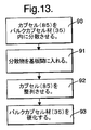
図2を参照すると、一方の基板壁部(3a,3b)上の電極(4a,4b)は、数字(11)の形になっており、その後、その数字(11)は、印加された電位(8)の上述のシーケンスと交互に表示させることができる。いくつかの英数字(11)/ディスプレイを有する単純なディスプレイを既に研究所レベルの実証に作製している。各場合には、全ての数字(11)の全てのセグメントは、別々の駆動回路(13)によって個別に駆動される。 Referring to FIG. 2, the electrodes (4a, 4b) on one substrate wall (3a, 3b) are in the form of a number (11), after which the number (11) represents the applied potential. (8) The above-mentioned sequence can be displayed alternately. A simple display with several alphanumeric (11) / displays has already been made for laboratory level demonstration. In each case, all segments of all numbers (11) are individually driven by separate drive circuits (13).
このようなディスプレイ(1)の通常の電気光学的挙動は、セルのマトリックス多重化を可能にするものではない。これは、光学的状態の変化が時間と電圧の積に依存する電気泳動セル(2)の特性によって引き起こされる。すなわち、セル全体に亘るほとんど任意の小さな電圧により、セルは、最終的に光学的状態を変えてしまう。
しかし、素子は、ある程度の閾値挙動をもたらすために粒子を基板に及び/又は互いに付着させるかなりのファンデルワールス力を用いて設計することができる。ところが、この付着力は、汚れに非常に敏感であり、一般的に、粒子の懸濁が最終的に失われ、粒子の綿状沈殿及び素子全体の故障に至る。
The normal electro-optical behavior of such a display (1) does not allow matrix multiplexing of cells. This is caused by the properties of the electrophoretic cell (2), where the change in optical state depends on the product of time and voltage. That is, almost any small voltage across the cell will eventually change the optical state of the cell.
However, the device can be designed with significant van der Waals forces that cause the particles to adhere to the substrate and / or to each other to provide some threshold behavior. However, this adhesion is very sensitive to soiling and generally results in a final loss of particle suspension leading to particle fluffing and failure of the entire device.
図3を参照すると、本発明による電気泳動ディスプレイの実施形態は、電気泳動材料(6)の粒子が液晶材料(20)を含む懸濁媒質(7)内で懸濁し、かつ、システムの幾何学形状が液晶材料(20)内で欠陥(21)を促進させるように配置された電気泳動システムを含む。欠陥(21)は、液晶材料(20)の配向対称の局所的破壊、例えば、液晶ダイレクタの配向順序の局所的破壊と考えることができる。このような欠陥(21)は、液晶材料(20)内の回位ということがある。 Referring to FIG. 3, an embodiment of an electrophoretic display according to the present invention comprises an electrophoretic material (6) particle suspended in a suspending medium (7) comprising a liquid crystal material (20) and the geometry of the system. It includes an electrophoresis system whose shape is arranged to promote defects (21) in the liquid crystal material (20). The defect (21) can be considered as a local destruction of the alignment symmetry of the liquid crystal material (20), for example, a local destruction of the alignment order of the liquid crystal director. Such a defect (21) may be referred to as a disclination in the liquid crystal material (20).
液晶材料(20)内の欠陥(21)は、電気泳動粒子を引き付けるように構成される。各欠陥(21)は、液晶材料(20)内で影響を有する関連領域を生じる。
この構成においては、電気泳動材料(6)の粒子の存在は、粒子(6)周辺部における液晶材料(20)のアラインメントを歪ませるものであり、従って、粒子(6)は、システム内で移動性の欠陥(21)又は欠陥の集合として作用する。電気泳動材料の粒子は、それが懸濁媒質(7)の塊の中にある時、印加された電位の影響を受けて比較的自由に移動する。しかし、粒子が液晶材料(20)内で欠陥(21)の影響がある領域内にある時、欠陥(21)と粒子(6)の間で相互作用が発生することにより、粒子(6)は、影響領域に関連する欠陥に向けて引き付けられる。妨害されなかった場合は、粒子(6)は、欠陥(21)によるシステム内の弾性エネルギが最小限に抑えられる好ましい位置を取るために影響領域内を移動する。
The defect (21) in the liquid crystal material (20) is configured to attract electrophoretic particles. Each defect (21) results in an associated region having an effect in the liquid crystal material (20).
In this configuration, the presence of particles of the electrophoretic material (6) distorts the alignment of the liquid crystal material (20) in the periphery of the particles (6), so that the particles (6) move within the system. Acts as a sex defect (21) or a collection of defects. When the particles of electrophoretic material are in the mass of the suspending medium (7), they move relatively freely under the influence of the applied potential. However, when the particle is in the region of the liquid crystal material (20) that is affected by the defect (21), the interaction between the defect (21) and the particle (6) occurs, so that the particle (6) Attracted towards defects related to the affected area. If not disturbed, the particles (6) move in the affected area to take a preferred position where the elastic energy in the system due to the defect (21) is minimized.
システム内の総液晶欠陥エネルギは、粒子(6)と欠陥(21)ができるだけ接近した状態であり、場合によっては重なり合っている時に最小限に抑えられ、その場合、欠陥つまり回位は実質的に消滅する。欠陥(21)同士が相互作用つまり消滅した時、粒子(6)は、欠陥(21)が最初に発生するか又は発生させられたディスプレイ内の地点(以下、欠陥コアという)に付着する傾向がある。
印加された電位がない場合、電気泳動材料(6)の粒子は、欠陥コアに関連する好ましい位置に留まる傾向がある。これは、材料のエネルギが、粒子(6)が塊状の液晶材料(20)内にある時よりもこの構成(粒子が欠陥コア近傍又はその上にある状態)の方が低いからである。これによって、電気泳動材料がファンデルワールス引力及び静電力のためにディスプレイの表面に単に付着する従来の電気泳動ディスプレイよりも、装置によって表示される画像の長期的な耐久性が改善されるという利点が得られる。また、電気泳動粒子の綿状沈殿が低減されることにより、装置の寿命が長くなる。
The total liquid crystal defect energy in the system is minimized when the particles (6) and the defects (21) are as close as possible and in some cases overlap, in which case the defects or dislocations are substantially reduced. Disappear. When the defects (21) interact or disappear, the particles (6) tend to adhere to the point in the display where the defects (21) are first generated or generated (hereinafter referred to as a defective core). is there.
In the absence of an applied potential, the particles of electrophoretic material (6) tend to remain in a preferred position relative to the defective core. This is because the energy of the material is lower in this configuration (in the vicinity of or above the defect core) than when the particles (6) are in the bulk liquid crystal material (20). This has the advantage that the long-term durability of the image displayed by the device is improved over conventional electrophoretic displays where the electrophoretic material simply adheres to the surface of the display due to van der Waals attraction and electrostatic forces Is obtained. In addition, the life of the apparatus is extended by reducing the flocculent precipitation of the electrophoretic particles.
電気泳動材料(6)の粒子を欠陥コアに関連する好ましい位置から移動させるには、欠陥(21)の分離に関連する潜在的エネルギバリアを克服するのに十分な電位をディスプレイに印加すべきであり、すなわち、欠陥がなくなった場合は、印加された電位は、欠陥コア及び電気泳動材料(6)の粒子における欠陥を再形成することができるべきである。
上述のように、欠陥は、液晶の弾性エネルギを低減させるために互いに相互作用する。従って、粒子(6)に関連する欠陥は、液晶セル内の好ましい位置に関連する欠陥の影響を受ける。一般的に、液晶セルの特定の領域においては、1つの特定の欠陥が優勢である。このようにして、システム弾性エネルギは、粒子(6)を粒子(6)に関連する欠陥と反対の強さを有する欠陥に向けて粒子を移動させることによって低減される。逆に、粒子(6)を引き付けられている欠陥から分離させるために印加電位によって仕事を行なわなければならない。理論的には、印加された電位によって十分な仕事が行われた状態であれば、液晶セル内の好ましい位置に関連する欠陥から粒子に与える影響が無視することができるほどである液晶セル領域に粒子(6)を移動させることができる。印加された場の大きさが不十分だった場合、又は粒子が影響のある特定領域に留まるような短時間に亘って場が印加されたに過ぎない場合、粒子は、弛緩して最初の位置に戻る。この閾値挙動は、非線形の電気光学特性をディスプレイに与えるものであり、装置の受動的マトリックスアドレス指定を可能にするものである。
To move the particles of electrophoretic material (6) from the preferred location associated with the defect core, a potential sufficient to overcome the potential energy barrier associated with the separation of the defect (21) should be applied to the display. Yes, that is, if the defect is gone, the applied potential should be able to recreate the defect in the defect core and particles of the electrophoretic material (6).
As mentioned above, the defects interact with each other to reduce the elastic energy of the liquid crystal. Thus, the defects associated with the particles (6) are affected by the defects associated with the preferred location in the liquid crystal cell. In general, one specific defect is dominant in a specific region of the liquid crystal cell. In this way, the system elastic energy is reduced by moving the particles towards a defect having a strength opposite to that associated with the particle (6). Conversely, work must be done with the applied potential to separate the particles (6) from the attracted defects. Theoretically, if sufficient work is performed by the applied potential, the effect on the particles from the defects associated with the preferred position in the liquid crystal cell is negligible. The particles (6) can be moved. If the applied field is not large enough, or if the field is only applied for a short time such that the particle remains in the specific area of influence, the particle will relax to its initial position. Return to. This threshold behavior imparts non-linear electro-optic properties to the display and allows for passive matrix addressing of the device.
図4は、欠陥からの距離の関数としての本発明による電気泳動セル内の弾性エネルギのグラフを示す。図4のグラフは、単一の欠陥を含み、単一の泳動粒子を有する電気泳動セルを表す。この場合、欠陥からセル内に延びる影響の単一領域がある。実際には、影響のこの領域は、欠陥(21)から50μmを超えて延びてもよい。
電気泳動材料(6)の粒子は、欠陥(21)の影響領域内にある時に力に遭遇することになる。粒子に関連する欠陥が欠陥コアの欠陥と反対の符号を有する場合、その力は、粒子(6)を欠陥コア(21)に引き付ける。妨害されなかった場合、電気泳動材料(6)は、欠陥(21)によるシステム内の弾性エネルギが最小限に抑えられる好ましい位置(第1の好ましい位置)を取るために影響領域内を移動する。
FIG. 4 shows a graph of elastic energy in an electrophoresis cell according to the present invention as a function of distance from a defect. The graph of FIG. 4 represents an electrophoretic cell containing a single defect and having a single electrophoretic particle. In this case, there is a single region of influence extending from the defect into the cell. In practice, this area of influence may extend more than 50 μm from the defect (21).
The particles of electrophoretic material (6) will encounter a force when in the affected area of the defect (21). If the defect associated with the particle has the opposite sign as the defect in the defective core, the force attracts the particle (6) to the defective core (21). If not disturbed, the electrophoretic material (6) moves in the affected area to take a preferred position (first preferred position) where the elastic energy in the system due to the defect (21) is minimized.
図4に表されている電気泳動セルについては、粒子(6)が欠陥コア(21)から移動ことができる最も長い距離を制限することによって単安定構成を達成することができる。このように影響領域内の粒子(6)の動きを制限することにより、印加された電位がない場合は、粒子(6)は、確実に第1の好ましい位置に戻る。
明瞭さを期すために、本発明は、非線形の電気光学的挙動をもたらすために懸濁媒質(7)内の液晶材料(20)の見掛け粘性を感知することができるほどの任意の程度まで変更していないことに注意すべきである(米国特許第4,305,807号とは対照的)。実際には、本発明においては、液晶ダイレクタは、懸濁媒質(7)内の液晶材料(20)が常に最低の粘性を示すように整列される。更に、本発明による電気泳動セルへの電位の印加が液晶ダイレクタの向きの変更に関して与える影響は、無視することができるほどのものである。同様に、本発明の電気泳動セル内の欠陥つまり回位は、それらがシステムの幾何学形状によって生成されるものであり、従って、電気泳動セル内で実質的に固定されるので、印加された電位による影響を受けないままである。
For the electrophoresis cell represented in FIG. 4, a monostable configuration can be achieved by limiting the longest distance that the particles (6) can move from the defective core (21). Limiting the movement of the particles (6) in the affected area in this way ensures that the particles (6) return to the first preferred position in the absence of an applied potential.
For the sake of clarity, the invention has been modified to any degree that allows the apparent viscosity of the liquid crystal material (20) in the suspending medium (7) to be sensed in order to provide non-linear electro-optic behavior. Note that this is not done (as opposed to US Pat. No. 4,305,807). In practice, in the present invention, the liquid crystal directors are aligned so that the liquid crystal material (20) in the suspension medium (7) always exhibits the lowest viscosity. Furthermore, the influence of the application of a potential to the electrophoresis cell according to the present invention with respect to the change in the orientation of the liquid crystal director is negligible. Similarly, defects or disclinations in the electrophoresis cell of the present invention are applied because they are created by the geometry of the system and are therefore substantially fixed in the electrophoresis cell. It remains unaffected by the potential.
ここで図5を参照すると、双安定ディスプレイは、液晶材料(20)内の欠陥(21)を電気泳動ディスプレイ内の対向する平面上に配置することによって作製することができる。例えば、第1の組の欠陥(21)は、ディスプレイの第1の(前部)表面(24)に配置され、第2の組の欠陥(21)は、ディスプレイ第2の(後部)表面(26)に配置される。この実施形態では、電気泳動材料(6)の粒子は、閾値レベルを超える電位の印加によってディスプレイの第1の表面(24)から第2の表面(26)(及び、その逆)に移動するように働き掛けることができる。 Referring now to FIG. 5, a bistable display can be made by placing defects (21) in the liquid crystal material (20) on opposing planes in the electrophoretic display. For example, a first set of defects (21) is located on the first (front) surface (24) of the display, and a second set of defects (21) is present on the display second (rear) surface ( 26). In this embodiment, the particles of electrophoretic material (6) are moved from the first surface (24) of the display to the second surface (26) (and vice versa) by the application of a potential that exceeds a threshold level. Can work on.
図3と共通するが、粒子(6)が引き付けられている欠陥から粒子を離すために印加される電位によって仕事を行わなければならない。印加された電位によって十分な仕事が行われた状態で、粒子(6)を別の欠陥が優勢である液晶セルの領域に移動させることができる。そこで、粒子は、この新しい欠陥に関連する好ましい位置であるセル内の新しい位置に弛緩されて移動する。この第2の欠陥の影響が最も大きい領域に到達した状態で、セルに電位を印加されるということが不要である。従って、粒子(6)が弛緩されてセル内の新しい位置に移動するように、最初の位置から十分に離れた位置に粒子(6)を移動させるために印加された電位内の閾値が必要である。上述の場合のように、印加された場が不十分であった場合、粒子(6)は最初の位置に戻る。 In common with FIG. 3, the work must be done by the potential applied to separate the particles from the defects to which the particles (6) are attracted. With sufficient work done by the applied potential, the particles (6) can be moved to the region of the liquid crystal cell where another defect predominates. The particles then move relaxed to a new location within the cell, which is the preferred location associated with this new defect. It is not necessary to apply a potential to the cell in a state where the region having the greatest influence of the second defect has been reached. Therefore, a threshold within the applied potential is required to move the particle (6) to a position sufficiently away from the initial position so that the particle (6) is relaxed and moved to a new position in the cell. is there. If the applied field is insufficient, as in the case described above, the particle (6) returns to the initial position.
図6は、2つの対向する欠陥間の距離の関数としての本発明による双安定電気泳動セル又は多重安定電気泳動セル内の弾性エネルギのグラフを示す。
図6のグラフは、2つの対向する欠陥(21)を有し、かつその間に配置された単一の泳動材料(6)を有する電気泳動セルを表す。この場合、第1の欠陥コア(21)からセル内に延びる第1の影響領域と、第2の欠陥コア(21)からセル内に延びる第2の影響領域(21)とがある。
FIG. 6 shows a graph of elastic energy in a bistable or multistable electrophoresis cell according to the present invention as a function of the distance between two opposing defects.
The graph of FIG. 6 represents an electrophoretic cell having two opposing defects (21) and having a single electrophoretic material (6) disposed therebetween. In this case, there is a first affected area extending from the first defective core (21) into the cell and a second affected area (21) extending from the second defective core (21) into the cell.
上述のように、電気泳動材料(6)の粒子は、欠陥(21)に関連する特定の影響領域内にある時に力に遭遇する。粒子(6)に関連する欠陥が欠陥コア(21)の欠陥と反対の符号を有する場合、その力は、粒子(6)を欠陥コア(21)に引き付ける。妨害されなかった場合、欠陥によるシステム内の弾性エネルギが最小限に抑えられる好ましい位置(この場合は、第1又は第2の好ましい位置)を取るために影響領域内で移動する。 As mentioned above, particles of electrophoretic material (6) encounter a force when they are within a specific affected area associated with defect (21). If the defect associated with the particle (6) has a sign opposite to that of the defect core (21), the force attracts the particle (6) to the defect core (21). If not disturbed, it moves within the affected area to take a preferred position (in this case the first or second preferred position) where the elastic energy in the system due to the defect is minimized.
一般的に、液晶セルの特定の領域においては、1つの特定の欠陥が優勢である。従って、粒子(6)が第1の影響領域内にある時は、第1の欠陥コア(21)に向けて引き付けられる。同様に、粒子(6)が第2の影響領域内にある時は、第2の影響領域(21)に引き付けられる。
システムの総弾性エネルギは、粒子(6)が2つの欠陥の均衡点にある状態で最も高いことが判明しているので、粒子(6)が欠陥のいずれかに向けて移動する時に小さくなる。
In general, one specific defect is dominant in a specific region of the liquid crystal cell. Therefore, when the particles (6) are in the first affected area, they are attracted towards the first defective core (21). Similarly, when the particle (6) is in the second influence area, it is attracted to the second influence area (21).
Since the total elastic energy of the system has been found to be highest when the particle (6) is at the equilibrium point of the two defects, it becomes smaller when the particle (6) moves towards one of the defects.
図6に表されている構成においては、好ましい位置間で粒子の移動に影響を与えるためには、第1の欠陥コアに関連する影響領域から第2の欠陥コアに関連する影響領域に粒子を移動させるだけで十分である。上述のように、これは、泳動粒子が特定の影響領域内にある状態では、欠陥に向けて引き付けられてその影響領域を生じるということによるものである。
セルに印加された電位は、電気泳動セル内のエネルギバリアを超えなければならず、また、粒子(6)を一方の影響領域から他方の影響領域に移動させるのに十分な時間に亘って印加されるべきである。
このようにして、電気泳動セルによって示された非線形の電気光学的挙動は、セル(E)に印加された電位の大きさと電位が印加される時間(t)との関数である。従って、電気泳動セルは、印加電位のマグニチュードに関係する静的閾値と、電位×印加電位マグニチュード(時間電圧積)に対する期間に関係する動的閾値とを示す。
In the configuration depicted in FIG. 6, in order to affect the movement of particles between preferred locations, particles are moved from the affected area associated with the first defective core to the affected area associated with the second defective core. It is enough to move it. As described above, this is due to the fact that when the migrating particles are in a particular affected area, they are attracted towards the defect to produce that affected area.
The potential applied to the cell must exceed the energy barrier in the electrophoresis cell and is applied for a time sufficient to move the particles (6) from one affected area to the other affected area. It should be.
Thus, the non-linear electro-optic behavior exhibited by the electrophoresis cell is a function of the magnitude of the potential applied to the cell (E) and the time (t) during which the potential is applied. Thus, the electrophoretic cell exhibits a static threshold related to the magnitude of the applied potential and a dynamic threshold related to the period of potential x applied potential magnitude (time voltage product).
動的閾値は、いくつかの従来の非電気泳動液晶素子、例えば、表面安定化強誘電ディスプレイ、ゼニス双安定素子(ZBD)、「Nemoptic BiNem(登録商標)」双安定液晶ディスプレイにおいて遭遇するものと類似のものである。
双安定ディスプレイは、電気泳動材料(6)の粒子が装置に印加された電位がない時には欠陥コアに縛られたままであるという利点をもたらす。更に、電気泳動材料(6)の粒子は、低レベル電位(装置の閾値レベル未満)がある場合でさえも欠陥コアに実質的に縛られたままである。これは、このような電位が多重化アドレス指定法では固有のものであることから有利なことである。従って、画像品質及び従って大面積アドレス指定機能は、装置内での電気泳動材料(6)の粒子の不要な移動を低減することによって保証される。
Dynamic thresholds may be encountered in some conventional non-electrophoretic liquid crystal devices, such as surface stabilized ferroelectric displays, Zenith bistable devices (ZBD), and “Nemoptic BiNem®” bistable liquid crystal displays. It is similar.
Bistable displays offer the advantage that the particles of electrophoretic material (6) remain bound to the defective core when there is no potential applied to the device. Furthermore, the particles of electrophoretic material (6) remain substantially bound to the defective core even when there is a low level potential (below the threshold level of the device). This is advantageous because such potentials are inherent in multiplexed addressing. Thus, image quality and thus large area addressing capability is ensured by reducing unwanted movement of particles of electrophoretic material (6) within the device.
液晶材料(20)における欠陥(21)又は回位は、このような欠陥を促進する任意の従来の幾何学形状によって導入することができる。例えば、従来の液晶ディスプレイの内面に対して好ましいアラインメント(平面又はホメオトロピック)を取るように液晶ダイレクタに働き掛けること、及び、回位を導入するために周期的な特徴をこれらの内面に適用することができることは当業技術で公知である。 Defects (21) or dislocations in the liquid crystal material (20) can be introduced by any conventional geometry that promotes such defects. For example, working liquid crystal directors to achieve a preferred alignment (planar or homeotropic) with respect to the inner surfaces of conventional liquid crystal displays, and applying periodic features to these inner surfaces to introduce dislocations Is known in the art.
図3及び図5に示す電気泳動ディスプレイの実施形態では、液晶材料(20)内の欠陥(21)は、深い二次元アレイによって導入される。一般的に、幾何学形状は、凹部のアレイを含むことができ、深さdを有する各凹部は、アレイ内でピッチpで配置される。凹部は、液晶材料内で欠陥(21)を生成するのに十分な深さである必要があり、この目的に沿うと、ピッチpに対する凹部の深さdの比率は、通常、少なくとも1/4になる。一般的に、深い凹部は、液晶材料内の欠陥の形成を助ける。
凹部深さ(d)/凹部ピッチ(p)≧1/4 [1]
In the embodiment of the electrophoretic display shown in FIGS. 3 and 5, the defects (21) in the liquid crystal material (20) are introduced by a deep two-dimensional array. In general, the geometry can include an array of recesses, with each recess having a depth d being arranged at a pitch p in the array. The recesses must be deep enough to create defects (21) in the liquid crystal material, and to this end, the ratio of the recess depth d to the pitch p is usually at least 1/4. become. In general, deep recesses help to form defects in the liquid crystal material.
Recess depth (d) / recess pitch (p) ≧ 1/4 [1]
一例として、電気泳動ディスプレイで使用された幾何学形状は、二次元アレイに配置された実質的に半楕円形、半回転楕円体、半球形又は「ヘミ」球形の凹部を含むことができる。凹部がディスプレイ内面で実質的に楕円形の断面を示す場合、半径は、その内面の楕円の主半軸の長さであるように取るものとする(半軸とは、軸の長さの半分を示す)。ディスプレイで使用される幾何学形状は、任意の従来の方法、例えば、フォトリソグラフィ及びエンボス加工などによってもたらすことができる。 As an example, the geometry used in the electrophoretic display can include substantially semi-elliptical, semi-spheroid, hemispherical or “hemi” spherical recesses arranged in a two-dimensional array. If the recess shows a substantially elliptical cross section on the inner surface of the display, the radius shall be taken to be the length of the major half axis of the ellipse on the inner surface (a half axis is half the length of the shaft) Showing). The geometry used in the display can be provided by any conventional method, such as photolithography and embossing.
電気泳動ディスプレイの内面は、ディスプレイ内で液晶材料(20)の好ましい向きをもたらすために、表面アラインメント処理を必要とするものとすることができる。図3及び図5に示す電気泳動ディスプレイの実施形態では、液晶材料(20)の平面アラインメントが利用されている。また、ディスプレイ内の電気泳動材料(6)の粒子に対して平面アラインメント処理を必要とする場合もある。
液晶材料(20)内の欠陥(21)の強度及び潜在的なエネルギバリアの対応するマグニチュードは、液晶材料(20)内の欠陥(21)を促進するために使用される幾何学形状のプロフィールに依存する。従って、潜在的なエネルギバリア及び従って電気泳動材料(6)の粒子を欠陥コアから移動させるために克服すべき閾値は、ディスプレイ内の幾何学形状のプロフィールを変えることにより、又は欠陥を促進するために使用される幾何学形状の表面での自然液晶予備傾斜又は固定エネルギを変えることにより調節することができる。
The inner surface of the electrophoretic display may require a surface alignment process to provide a preferred orientation of the liquid crystal material (20) within the display. The embodiment of the electrophoretic display shown in FIGS. 3 and 5 utilizes a planar alignment of the liquid crystal material (20). Further, there may be a case where a planar alignment process is required for the particles of the electrophoretic material (6) in the display.
The strength of the defect (21) in the liquid crystal material (20) and the corresponding magnitude of the potential energy barrier are in the profile of the geometry used to promote the defect (21) in the liquid crystal material (20). Dependent. Thus, the potential energy barrier and thus the threshold to be overcome in order to move the particles of electrophoretic material (6) out of the defect core is to change the geometry profile in the display or to promote defects Can be adjusted by changing the natural liquid crystal pre-tilt or fixed energy at the surface of the geometry used in the.
ディスプレイのアドレス指定要件に注意すると、電気泳動材料(6)の粒子をディスプレイの第1の表面(24)から移動させるために克服すべき閾値は、電気泳動材料(6)の粒子をディスプレイの第2の表面(26)から移動させるために克服すべき閾値と異なるように構成することができる。その結果、非対称の度合は、ディスプレイの第1及び第2の平面(24,26)の間で電気泳動材料(6)の粒子を移動させために必要とされる電位に組み込むことができ、正及び負の極性の電位に対する非対称のスイッチング閾値をもたらす。ディスプレイ が複数のセル又はピクセルを含む場合(多重セルディスプレイ)、このような非対称性は、多重化マトリックスアドレス指定を容易にするものであり、かつ、ディスプレイのアドレス指定を行うために使用されるライン前方ブランキングとして公知の技術を可能にするものである。ライン前方ブランキングは、ディスプレイを単一時間スロットでアドレス指定することを可能にする(すなわち、ライン前方ブランキングを使用しなかった場合に掛かる時間の半分でディスプレイをアドレス指定することができる)。
当業技術で公知の標準的な多重化手法の例については、PWH Surgy他著「Joers/Alvey強誘電性多重化手法」、強誘電、122巻、63頁から79頁、1991年を参照することができる。
With attention to the addressing requirements of the display, the threshold to be overcome in order to move the particles of electrophoretic material (6) from the first surface (24) of the display is that the particles of electrophoretic material (6) are not It can be configured to be different from the threshold to be overcome to move from the second surface (26). As a result, the degree of asymmetry can be incorporated into the potential required to move the particles of electrophoretic material (6) between the first and second planes (24, 26) of the display and are positive. And an asymmetric switching threshold for negative polarity potentials. If the display contains multiple cells or pixels (multi-cell display), this asymmetry facilitates multiplexed matrix addressing and the lines used to perform display addressing. A technique known as forward blanking is made possible. Line forward blanking allows the display to be addressed in a single time slot (ie, the display can be addressed in half the time it would take if line forward blanking was not used).
For examples of standard multiplexing techniques known in the art, see PWH Surgy et al., “Joers / Alvey Ferroelectric Multiplexing Technique”, Ferroelectric, Vol. 122, 63-79, 1991. be able to.
上述の特定の実施形態で説明するような電気泳動セルを作製するための本発明による方法は、以下の段階を含む。
電極パターンを有する基板を準備する。共形層を形成するためにフォトレジストを基板表面上で引き伸ばす。例えば、「Shipley Megaposit SPR220−7」を基板に付加し、2000rpmで基板を30秒間回転させる。
製造業者の指示書に従ってフォトレジストを処理する。一般的に、レジスト溶剤を除去するために基板を加熱する。
The method according to the present invention for making an electrophoretic cell as described in the specific embodiment above comprises the following steps.
A substrate having an electrode pattern is prepared. The photoresist is stretched over the substrate surface to form a conformal layer. For example, “Shipley Megaposition SPR220-7” is added to the substrate, and the substrate is rotated at 2000 rpm for 30 seconds.
Process the photoresist according to the manufacturer's instructions. Generally, the substrate is heated to remove the resist solvent.
次に、従来の光リソグラフ手法を用いてフォトレジストに凹部の二次元アレイを形成する。上述のように、凹部は、実質的に半楕円形、半回転楕円体、半球形又は「ヘミ」球形とすることができる。一般的に、フォトレジストにパターンを形成するためにマスクとUV光源を使用する。例えば、フォトレジストの各部を優先的に露光させるために高エネルギビーム感受性(HEBS)グレースケールフォトマスク(キャニオン・マテリアルズ・インコーポレーテッド製)を使用することができる。その後、フォトレジストが作成され、例えば、処理済み基板を洗浄することによってレジストの不要な部分を除去する。その後、これによって、図3及び図5に示す表面レリーフ形状が得られる。 Next, a two-dimensional array of recesses is formed in the photoresist using conventional optical lithography techniques. As described above, the recesses can be substantially semi-elliptical, semi-spheroid, hemispherical or “hemi” spherical. In general, a mask and a UV light source are used to form a pattern in a photoresist. For example, a high energy beam sensitive (HEBS) gray scale photomask (made by Canyon Materials, Inc.) can be used to preferentially expose portions of the photoresist. Thereafter, a photoresist is created, and unnecessary portions of the resist are removed, for example, by washing the processed substrate. Thereafter, the surface relief shape shown in FIGS. 3 and 5 is obtained.
フォトレジストを架橋させることによって溶剤に対する抵抗を向上させるために基板を処理する。任意的に、フォトレジストを深UV放射線に露光させ、その後、フォトレジストを硬化させるために2時間120℃で強く焼きつけをする。
最後に、フォトレジスト基板を電気泳動セルに直接に組み込むか又は成形及びエンボス加工処理を用いて複製する(後者の場合、電極パターンを基板から省略することができる)。
The substrate is treated to improve resistance to solvents by crosslinking the photoresist. Optionally, the photoresist is exposed to deep UV radiation, followed by strong baking at 120 ° C. for 2 hours to cure the photoresist.
Finally, the photoresist substrate is incorporated directly into the electrophoresis cell or replicated using molding and embossing (in the latter case, the electrode pattern can be omitted from the substrate).
例えば、準備した基板を液晶懸濁媒質及び複数の電気泳動粒子を組み込んだ電気泳動セルに組み込むことができる。電気泳動粒子は、通常、液晶懸濁媒質をセルに添加する前に組み付け処理の一部としてセル基板の1つの上に堆積される。
毛細菅法を用いて組み付けた電気泳動セルに液晶懸濁媒質を組み込む。代替的に、従来の真空充填を用いることにより、電気泳動セル内に溜まった空気が除去される。セル内の電気泳動粒子の擾乱を最小限に抑えるために、液晶をセルにゆっくりと添加する。
For example, the prepared substrate can be incorporated into an electrophoresis cell incorporating a liquid crystal suspension medium and a plurality of electrophoretic particles. Electrophoretic particles are typically deposited on one of the cell substrates as part of the assembly process prior to adding the liquid crystal suspension medium to the cell.
A liquid crystal suspension medium is incorporated into an electrophoresis cell assembled using the capillary wrinkle method. Alternatively, air accumulated in the electrophoresis cell is removed by using conventional vacuum filling. In order to minimize the disturbance of the electrophoretic particles in the cell, liquid crystal is slowly added to the cell.
液晶材料は、一般的に等方相でセルに添加され、その後、急激に室温に冷却させる。公知のシュリーレンテクスチャが形成されるが、セル内の表面レリーフは、ほとんどの欠陥が凹部の基部近くに形成されるのを促す。装置のその後のスイッチングにより、セル内の正しい液晶アラインメントが補強される。
電気泳動セルは、レリーフ構造を有する単一の基板を含むことができる。代替的に、準備した2つの基板を組み付けて電気泳動セルにし、かつ第1の基板上のレリーフ構造表面の各凹部が、第2の基板上のレリーフ構造表面の対向する凹部と実質的に反対となるように配置され、この凹部は、一対の凹部を形成する。一般的に、泳動粒子は、凹部の各対向する対内に配置される。
The liquid crystal material is generally added to the cell in an isotropic phase and then rapidly cooled to room temperature. Although known schlieren textures are formed, the surface relief in the cell encourages most defects to form near the base of the recess. Subsequent switching of the device reinforces the correct liquid crystal alignment within the cell.
The electrophoresis cell can include a single substrate having a relief structure. Alternatively, the two prepared substrates are assembled into an electrophoretic cell, and each recess in the relief structure surface on the first substrate is substantially opposite to the opposite recess in the relief structure surface on the second substrate. These recesses form a pair of recesses. Generally, migrating particles are placed in each opposing pair of recesses.
準備した基板を直接使用しない場合、金型を用いて凹部のアレイを複製することができる。例えば、ポリジメチルシロキサン(PDMS)を使用することができる。
「Dow Corning Sylgard 182」のようなポリジメチルシロキサン(PDMS)エラストマーシステムが選択される。これは、二瓶システムであり、2つの成分を混合させることによって準備する。
凹部のアレイを有する準備した基板をマスターとして使用してPDMS調剤で覆う。基板を真空室に入れて、溜まった気泡を除去するために空気抜きをする。PMDSが硬化するまでシステムを放置する。任意的に、硬化処理を速めるために基板を加熱する。
If the prepared substrate is not used directly, the array of recesses can be replicated using a mold. For example, polydimethylsiloxane (PDMS) can be used.
A polydimethylsiloxane (PDMS) elastomer system such as “Dow Corning Sylgard 182” is selected. This is a two-bottle system, prepared by mixing the two components.
A prepared substrate with an array of recesses is used as a master and covered with a PDMS formulation. The substrate is placed in a vacuum chamber and air is vented to remove the accumulated bubbles. Leave the system until the PMDS is cured. Optionally, the substrate is heated to speed up the curing process.
硬化した状態で、PMDS型は、マスターから取り外されて洗浄される。一般的に、本方法でマスターからいくつかのPDMS複製を作ることができる。その後、付加的な成形法又はエンボス加工処理を通じて凹部の元となる二次元アレイを複製するためにPDMS型を使用する。
最終的な成形処理に幅広い材料を使用することができる。1つのこのような材料は、UV硬化接着剤である「Norland 81」である。
適切な基板を選んで、成形される材料の薄い層でコーティングする。一般的には、基板は、成形される材料の5μm厚の層でコーティングされる。
In the cured state, the PMDS mold is removed from the master and cleaned. In general, several PDMS replicas can be made from a master with this method. The PDMS mold is then used to replicate the two-dimensional array that forms the recesses through additional molding or embossing processes.
A wide range of materials can be used for the final molding process. One such material is “Norland 81” which is a UV curable adhesive.
An appropriate substrate is selected and coated with a thin layer of the material to be molded. In general, the substrate is coated with a 5 μm thick layer of the material to be molded.
その後、コーティングした基板をPMDS型と共に真空室に入れ、システムの空気抜きをすることにより、PMDS型が薄い層に接触する。
任意的に、その後、型と基板を真空室から取り出すことができる。その後、成形可能な材料を硬化させる。「Norland 81」の場合、材料をUV光に露光させて硬化させる。最後に、PDMS型を基板から取り外す。
UV硬化可能な材料の代わりとして熱硬化式の成形可能な材料を使用することができる。熱硬化では、基板と成形された材料を加熱する必要がある。
The coated substrate is then placed in a vacuum chamber with the PMDS mold, and the PMDS mold contacts the thin layer by venting the system.
Optionally, the mold and substrate can then be removed from the vacuum chamber. Thereafter, the moldable material is cured. In the case of “Norland 81”, the material is exposed to UV light and cured. Finally, the PDMS mold is removed from the substrate.
Thermoset moldable materials can be used as an alternative to UV curable materials. In thermosetting, it is necessary to heat the substrate and the molded material.
更に別の実施形態では、成形可能な材料は、熱可塑性材料を含むことができる。この場合、型を熱可塑性材料に接触させる前に熱可塑性材料を真空室で加熱する。型を熱可塑性材料に接触させたら、自然冷却させることができる。熱可塑性材料が冷却したら型を基板から取り外す。
型はまた、公知の手法を用いてPMDS以外の材料から作ることができ、例えば、ニッケルを型に使用することができることに注意すべきである。
In yet another embodiment, the moldable material can comprise a thermoplastic material. In this case, the thermoplastic material is heated in a vacuum chamber before contacting the mold with the thermoplastic material. Once the mold is in contact with the thermoplastic material, it can be allowed to cool naturally. When the thermoplastic material has cooled, the mold is removed from the substrate.
It should be noted that the mold can also be made from materials other than PMDS using known techniques, for example, nickel can be used for the mold.
図7を参照すると、本発明による電気泳動ディスプレイの更に別の実施形態は、マイクロカプセル化電気泳動システムを含む。マイクロカプセル化電気泳動システムは、一般的に、液晶材料(20)を含む液滴(30)のアレイを含む。各液滴(30)は、電気泳動材料の粒子(6)を取り囲む。
先の実施形態の場合と同様に、電気泳動材料(6)の粒子は、液晶材料(20)を含む懸濁媒質(7)内で懸濁状態である。しかし、この実施形態では、懸濁媒質(7)は、カプセル材(35)内に配置された複数の離散的液晶材料(20)液滴(30)を含み、各液滴(30)は、その中に電気泳動粒子が分散されている(6)。
Referring to FIG. 7, yet another embodiment of the electrophoretic display according to the present invention includes a microencapsulated electrophoretic system. A microencapsulated electrophoresis system generally includes an array of droplets (30) comprising liquid crystal material (20). Each droplet (30) surrounds a particle (6) of electrophoretic material.
As in the previous embodiment, the particles of the electrophoretic material (6) are in a suspended state in the suspension medium (7) containing the liquid crystal material (20). However, in this embodiment, the suspending medium (7) comprises a plurality of discrete liquid crystal material (20) droplets (30) arranged in an encapsulant (35), each droplet (30) being Electrophoretic particles are dispersed therein (6).
例えば、カプセル材(35)は、任意の適切な結合剤を含むことができ、液晶材料の液滴(30)を結合剤に分散させることによってマイクロカプセル化電気泳動ディスプレイを形成する。
特定の例においては、マイクロカプセル化電気泳動システムは、ポリマーマトリックス内に分散された液晶材料(20)の液滴(30)を有するポリマー分散液晶(PDLC)ディスプレイを含むことができる。
For example, the encapsulant (35) can include any suitable binder and forms a microencapsulated electrophoretic display by dispersing liquid crystal material droplets (30) in the binder.
In a particular example, the microencapsulated electrophoresis system can include a polymer dispersed liquid crystal (PDLC) display having droplets (30) of liquid crystal material (20) dispersed within a polymer matrix.
図7を参照すると、液晶材料(20)の液滴(30)内の電気泳動材料(6)の位置は、液晶材料(20)及び内部液滴(30)表面間のインタフェース、及び液晶材料(20)及び電気泳動材料(6)表面間のインタフェースでの液晶固定条件の慎重な選択によって制御される。本質的に非ホメオトロピック固定条件が液滴(30)の内面及び電気泳動粒子(6)の表面の両方にある状態で、図示のトポロジーによってこれらの表面で欠陥が強制的に生成される。 Referring to FIG. 7, the position of the electrophoretic material (6) within the droplet (30) of the liquid crystal material (20) depends on the interface between the surface of the liquid crystal material (20) and the internal droplet (30), and the liquid crystal material ( 20) and electrophoretic material (6) controlled by careful selection of liquid crystal fixation conditions at the interface between the surfaces. With essentially non-homeotropic fixation conditions on both the inner surface of the droplet (30) and the surface of the electrophoretic particle (6), the illustrated topology forces defects to be generated on these surfaces.
表面アラインメント処理を用いて、各液滴(30)内に有利な固定条件(従って、液晶ダイレクタの有利なアラインメント)を作り出すことができる。適切な表面処理は、液晶ダイレクタの接線成分が助長されて傾斜又は平面アラインメントが得られる表面処理である。
表面アラインメント処理は、液滴内の第1(31)及び第2(32)の欠陥の形成を助ける。各液滴(30)内での欠陥(31,32)の位置決めは、液滴形状によって支配される。従って、液滴(30)の幾何学形状は、液滴内の欠陥(31,32)の位置を制御するように、かつ確実に欠陥(31,32)が液滴内で実質的に反対位置に配置されるようにカスタマイズすることができる。例えば、液滴(30)は、球又は回転楕円体(完全に球ではなく)となるように配置することができる。特に、欠陥(31,32)が幅広の回転楕円体液滴(30)の主(長)軸に沿って実質的に反対位置に配置された状態の幅広の回転楕円体構成を示すように液滴(30)をカスタマイズすることができる。
A surface alignment process can be used to create an advantageous fixing condition within each droplet (30) (and thus an advantageous alignment of the liquid crystal director). A suitable surface treatment is a surface treatment in which the tangential component of the liquid crystal director is promoted to obtain a tilted or planar alignment.
The surface alignment process helps to form first (31) and second (32) defects within the droplet. The positioning of the defect (31, 32) within each droplet (30) is governed by the droplet shape. Thus, the geometry of the droplet (30) controls the position of the defect (31, 32) within the droplet and ensures that the defect (31, 32) is in a substantially opposite position within the droplet. Can be customized to be placed in. For example, the droplet (30) can be arranged to be a sphere or spheroid (not completely a sphere). In particular, the droplets so as to show a wide spheroid configuration with the defects (31, 32) disposed substantially opposite positions along the main (long) axis of the wide spheroid droplet (30). (30) can be customized.
各液滴(30)内での欠陥(31,32)の作成により、画像メモリを有するディスプレイを採用し、従ってそれを容易にするための電気泳動材料(6)の粒子に対する2つの可能な位置が得られる。
表面アラインメント処理は、各液滴(30)内で懸濁状態である電気泳動材料の粒子に適用することができる。電気泳動材料(6)の粒子に適用された表面処理は、液晶ダイレクタの接線成分を励起し、ここでもまた、粒子(6)の表面で傾斜又は平面アラインメントが得られるものであるべきである。電気泳動材料(6)の粒子の表面での2つの対向する欠陥(33,34)を促進するために表面アラインメント処理が用いられる。
The creation of defects (31, 32) within each droplet (30) employs a display with an image memory and thus two possible positions relative to the particles of electrophoretic material (6) to facilitate it. Is obtained.
The surface alignment process can be applied to particles of electrophoretic material that are suspended within each droplet (30). The surface treatment applied to the particles of electrophoretic material (6) should excite the tangential component of the liquid crystal director and again provide a tilt or planar alignment at the surface of the particles (6). A surface alignment process is used to promote two opposing defects (33, 34) at the surface of the particles of electrophoretic material (6).
図7に示すように、電気泳動材料(6)が液晶材料(20)の塊内、すなわち、液滴(30)内の欠陥(31,32)から離れた位置に配置された時、システムは、液滴(30)内の欠陥(31,32)及び粒子(6)表面の欠陥のために特定の液晶欠陥エネルギを示す。システム内の総欠陥エネルギは、システム内の欠陥(31,32,33,34)の強度と位置の関数である。
電気泳動材料(6)の粒子は、液滴(30)への電位の印加によって液滴(30)内で移動するように働き掛けることができる。
粒子(6)の表面上の欠陥(33,34)が液滴(30)内の欠陥(31,32)の周辺部にある時は、欠陥間で相互作用が発生する。粒子(6)が液滴(30)内の欠陥(31,32)の周辺部にある時は、システム内の総液晶欠陥エネルギは、電気泳動粒子(6)が液晶材料(20)の塊内、つまり、液滴(30)内の欠陥(31,32)から離れた位置にある時よりも低い。実際に、システム内の総液晶欠陥エネルギのこの低減は、粒子(6)表面上の欠陥(33,34)が互いに近づいた時に液滴内の欠陥(31,32)に引き付けられる傾向を生じる機構である。
As shown in FIG. 7, when the electrophoretic material (6) is placed in the mass of liquid crystal material (20), ie, away from the defects (31, 32) in the droplet (30), the system Specific liquid crystal defect energy is indicated due to defects (31, 32) in the droplet (30) and defects on the surface of the particle (6). The total defect energy in the system is a function of the intensity and position of the defects (31, 32, 33, 34) in the system.
The particles of electrophoretic material (6) can be driven to move within the droplet (30) by the application of a potential to the droplet (30).
When the defect (33, 34) on the surface of the particle (6) is in the periphery of the defect (31, 32) in the droplet (30), an interaction occurs between the defects. When the particles (6) are in the periphery of the defects (31, 32) in the droplet (30), the total liquid crystal defect energy in the system is such that the electrophoretic particles (6) are in the mass of the liquid crystal material (20). That is, it is lower than when it is at a position away from the defect (31, 32) in the droplet (30). In fact, this reduction in total liquid crystal defect energy in the system is a mechanism that causes the defects (33, 34) on the particle (6) surface to tend to be attracted to defects (31, 32) in the droplets as they approach each other. It is.
従って、システム内の総液晶欠陥エネルギは、粒子(6)表面上の欠陥(33,34)と液滴内の欠陥(31,32)とが重ね合わされた時に最小限に抑えられる。この場合、液滴(30)の幾何学形状及び粒子(6)が許す場合、欠陥によって占められる容積はゼロであるべきである。液滴(30)の幾何学形状及び粒子(6)がより低い程度まで協働した場合、欠陥は、液滴内の小さいが明確な容積を占めるべきである。上述の配置のいずれにおいても、総液晶欠陥エネルギは最小限に抑えられ、また、欠陥は実質的に消滅する。これによって、電気泳動材料(6)の粒子は、液滴(30)の内面に付着するように働きかけられるので、この地点から粒子(6)を移動させるように仕事を行わなければならない。
システムの総弾性エネルギは、粒子(6)が液滴(30)の釣り合い点にある状態で最も高いことが判明しているので、粒子(6)が液滴(30)のいずれかの端部に移動した時に小さくなる。
Thus, the total liquid crystal defect energy in the system is minimized when the defects (33, 34) on the surface of the particle (6) and the defects (31, 32) in the droplet are superimposed. In this case, if the geometry of the droplet (30) and the particles (6) allow, the volume occupied by the defect should be zero. If the droplet (30) geometry and particles (6) cooperate to a lesser extent, the defect should occupy a small but well-defined volume within the droplet. In any of the above arrangements, the total liquid crystal defect energy is minimized and the defects are substantially extinguished. As a result, the particles of the electrophoretic material (6) are urged to adhere to the inner surface of the droplet (30), so work must be done to move the particles (6) from this point.
Since the total elastic energy of the system has been found to be highest with the particle (6) at the equilibrium point of the droplet (30), the particle (6) is at either end of the droplet (30). Smaller when moved to.
ディスプレイの作動を図8aから図8dに示す。
特に図8aを参照すると、印加された電位がない場合、システムは安定した状態を取り、電気泳動材料(6)の粒子は、一端、例えば液滴(30)の上部に留まる。上方から見ると、電気泳動材料(6)の粒子は、下にある懸濁媒質(7)を曖昧にし、従って、液滴は、実質的に電気泳動材料(6)の粒子の色であるように見える。
The operation of the display is shown in FIGS. 8a to 8d.
With particular reference to FIG. 8a, in the absence of an applied potential, the system will remain stable and the particles of electrophoretic material (6) will remain at one end, eg, on top of the droplet (30). When viewed from above, the particles of electrophoretic material (6) obscure the underlying suspending medium (7) so that the droplets are substantially the color of the particles of electrophoretic material (6). Looks like.
特に図8bを参照すると、正しい極性を有した十分な大きさの電位(40)の印加により、電気泳動材料(6)の粒子が液滴の上部から移動し、同時に、2つの欠陥ができて、1つの欠陥(31)はその粒子が発生した位置に、別の欠陥(32)は電気泳動材料(6)の粒子の表面上にある。粒子(6)は、印加された電位(40)の影響を受けて液滴(30)の底部に向けて移動する。電気泳動材料(6)の粒子が液滴(30)の底部に到達すると、粒子表面上の欠陥(34)と液滴(30)の底部の欠陥(32)とが重なり合う。この時、システム内の総液晶欠陥エネルギは、電気泳動粒子(6)が液晶材料(20)の塊内、すなわち、液滴(30)内の欠陥(31,32)から離れた位置に配置された時よりも低い。重なり合った欠陥は、実質的に消滅する。電位(40)が除去された時でさえも、粒子(6)は、液滴(30)の底部に保持されている。上から見た時、懸濁媒質(7)は、電気泳動材料(6)の粒子を曖昧にし、従って、液滴は、実質的に懸濁媒質(7)の色であるように見える。 With particular reference to FIG. 8b, application of a sufficiently large potential (40) with the correct polarity causes the particles of electrophoretic material (6) to move from the top of the droplet, while simultaneously creating two defects. One defect (31) is at the location where the particle was generated and another defect (32) is on the surface of the particle of electrophoretic material (6). The particles (6) move toward the bottom of the droplet (30) under the influence of the applied potential (40). When the particles of the electrophoretic material (6) reach the bottom of the droplet (30), the defect (34) on the particle surface and the defect (32) at the bottom of the droplet (30) overlap. At this time, the total liquid crystal defect energy in the system is arranged such that the electrophoretic particles (6) are located in the mass of the liquid crystal material (20), that is, away from the defects (31, 32) in the droplet (30). Lower than when. Overlapping defects are virtually eliminated. Even when the potential (40) is removed, the particles (6) are retained at the bottom of the droplet (30). When viewed from above, the suspending medium (7) obscures the particles of the electrophoretic material (6), and thus the droplets appear to be substantially the color of the suspending medium (7).
特に図8cを参照すると、マグニチュードの低い逆電位(41)の印加は、粒子(6)を欠陥(32)から離れた位置に置くには不十分であり、従って、粒子(6)は、欠陥(32)の影響がある領域から除去されない。従って、電気泳動材料(6)の粒子は、場が除去された後に弛緩されて液滴(30)の底部の位置に戻る。
特に図8dを参照すると、マグニチュードが大きい逆電位(42)の印加により、電気泳動材料(6)の粒子が移動し、同時に、粒子(6)表面に欠陥(34)と液滴(30)の底部に欠陥(32)とができて、粒子(6)は、引っ張られて欠陥(32)の影響のある領域から出る。粒子(6)は、印加された電位(42)の影響を受けて液滴(30)上部の元の位置に戻る。粒子(6)が液滴(30)上部に到達すると、2つの欠陥(31,32)は重なり合う。システム内の総液晶欠陥エネルギは、ここでもまた、電気泳動粒子(6)が液晶材料(20)の塊内、つまり、液滴(30)内の欠陥(31,32)から離れた位置に配置されている時よりも低い。重なり合った欠陥は、実質的に消滅し、粒子(6)は、その位置に保持される。
With particular reference to FIG. 8c, the application of a low magnitude reverse potential (41) is insufficient to place the particle (6) away from the defect (32), so the particle (6) It is not removed from the area affected by (32). Thus, the particles of electrophoretic material (6) are relaxed after the field is removed and return to the bottom position of the droplet (30).
With particular reference to FIG. 8d, application of the reverse potential (42) having a large magnitude causes the particles of the electrophoretic material (6) to move, and at the same time, defects (34) and droplets (30) on the surface of the particle (6) A defect (32) is created at the bottom, and the particle (6) is pulled out of the area affected by the defect (32). The particles (6) return to their original position above the droplet (30) under the influence of the applied potential (42). When the particle (6) reaches the top of the droplet (30), the two defects (31, 32) overlap. Again, the total liquid crystal defect energy in the system is located where the electrophoretic particles (6) are located within the mass of liquid crystal material (20), i.e. away from the defects (31, 32) in the droplet (30). Lower than when it has been. Overlapped defects are substantially extinguished and the particles (6) are held in place.
図7及び図8に示す実施形態では、電気泳動粒子(6)への表面アラインメント処理の適用により、粒子(6)の大きさに関係なく、欠陥(33,34)が粒子(6)の表面上の液晶材料に生成されることが保証される。従って、電気泳動材料(6)の粒子は、光学的散乱を最大にして高コントラストディスプレイをもたらすように最適サイズになるように配置することができる。
実際は、電気泳動材料(6)の粒子は、液滴(30)の上部に位置する時に高程度の光学的散乱をもたらすのに十分な大きさであるように選択される。更に、粒子(6)は、液滴(30)の上部に位置する時に下にある懸濁媒質を実質的に隠すのに十分な大きさであるべきであり、図8a及び図8dを参照することができる。しかし、電気泳動材料(6)の粒子が液滴底部に位置する時(図8b及び図8cを参照することができる)、懸濁媒質(7)は、電気泳動粒子(6)を曖昧にすることができなければならず、これは、ディスプレイに選択された電気泳動材料(6)の粒子の大きさに影響を与える可能性がある。
In the embodiment shown in FIG. 7 and FIG. 8, by applying the surface alignment process to the electrophoretic particles (6), the defects (33, 34) are removed from the surface of the particles (6) regardless of the size of the particles (6). It is guaranteed to be produced in the above liquid crystal material. Thus, the particles of electrophoretic material (6) can be arranged to be optimally sized to maximize optical scattering and provide a high contrast display.
In practice, the particles of electrophoretic material (6) are selected to be large enough to provide a high degree of optical scattering when located on top of the droplet (30). Furthermore, the particles (6) should be large enough to substantially hide the underlying suspending medium when located on top of the droplet (30), see FIGS. 8a and 8d. be able to. However, when the particles of electrophoretic material (6) are located at the bottom of the droplet (see FIGS. 8b and 8c), the suspending medium (7) obscures the electrophoretic particles (6). This must be able to affect the particle size of the electrophoretic material (6) selected for the display.
一般的に、電気泳動粒子(6)の半径は、懸濁媒質(7)を適切に隠すことができるように、液滴(30)の半径の少なくとも30%であるように配置することができる。一般的に、電気泳動粒子(6)は、液滴(30)の半径の約50%の半径を呈する。液滴(30)が回転楕円体である場合、半径は、欠陥(31,32)が配置される軸に垂直に測定するものとする。例えば、液滴(30)が幅広の回転楕円体であり、かつ欠陥(31,32)が幅広の回転楕円体液滴(30)の主(長)軸に沿って実質的に反対位置に配置された場合、液滴(30)の半径は、液滴(30)の小(短)軸に沿って測定するものとする。 Generally, the radius of the electrophoretic particles (6) can be arranged to be at least 30% of the radius of the droplet (30) so that the suspension medium (7) can be properly hidden. . Generally, electrophoretic particles (6) exhibit a radius of about 50% of the radius of droplet (30). If the droplet (30) is a spheroid, the radius shall be measured perpendicular to the axis where the defect (31, 32) is located. For example, the droplet (30) is a wide spheroid and the defects (31, 32) are disposed substantially at opposite positions along the main (long) axis of the wide spheroid droplet (30). In this case, the radius of the droplet (30) is measured along the small (short) axis of the droplet (30).
電気泳動材料(6)の粒子の寸法は、ディスプレイ内の液晶(20)における欠陥の形成に関連するエネルギバリアに影響を与える可能性がある。従って、電気泳動粒子(6)の大きさは、潜在的なエネルギバリア及びその結果ディスプレイ内の電位閾値に影響を与える場合がある。以上のことに注意して、ディスプレイ内の電位閾値を調節するように粒子サイズを選択することができる。
実際には、電気泳動材料(6)の粒子の半径は、自然発生する分布内にある可能性があり、これによって、本発明によるマイクロカプセル化表示装置は、ある一定範囲のグレーレベル(グレースケール)表示することができる。例えば、ディスプレイ内の各ピクセルは、複数の液滴(30)を含むことができる。以上から、液滴(30)内の電気泳動粒子(6)の分布により、液滴(30)に関連する電位閾値での対応する分布が得られることになる。従って、ディスプレイ内の各ピクセルに適用される電位のマグニチュードは、そのピクセル内の光学的状態を変える液滴(30)数を支配することになる。この例においては、各ピクセルの反射率は、ピクセル内の液滴数及び各ピクセルの光学的状態と関係がある。従って、ピクセルの反射率は、ピクセルに適用された電位のマグニチュードに比例し(光学的状態を変える液滴数を支配する)、その結果、各ピクセルは、ある一定範囲のグレースケールを表示することができる。
The size of the particles of electrophoretic material (6) can affect the energy barrier associated with the formation of defects in the liquid crystal (20) in the display. Thus, the size of the electrophoretic particles (6) may affect the potential energy barrier and consequently the potential threshold in the display. With the above in mind, the particle size can be selected to adjust the potential threshold in the display.
In practice, the particle radius of the electrophoretic material (6) may be within a naturally occurring distribution, which allows the microencapsulated display device according to the present invention to have a range of gray levels (grayscale). ) Can be displayed. For example, each pixel in the display can include a plurality of droplets (30). From the above, the distribution of the electrophoretic particles (6) in the droplet (30) results in a corresponding distribution at the potential threshold associated with the droplet (30). Thus, the magnitude of the potential applied to each pixel in the display will dominate the number of droplets (30) that change the optical state in that pixel. In this example, the reflectance of each pixel is related to the number of droplets in the pixel and the optical state of each pixel. Thus, the reflectance of a pixel is proportional to the magnitude of the potential applied to the pixel (dominates the number of droplets that change the optical state), so that each pixel displays a range of gray scales. Can do.
図7及び図8に示す本発明の実施形態は、非線形の電気光学的挙動を有する画像メモリを伴うディスプレイをもたらすが、液滴(30)内の電気泳動材料(6)の粒子を移動させるのに必要な電位のある程度の非対称性を組み込み、正及び負極性の電位に対する非対称スイッチング閾値をもたらすアドレス指定を目的として有用であろう。上述のように、このような非対称性は、多重セルディスプレイの多重化マトリックスアドレス指定を容易にし、かつ、ディスプレイをアドレス指定するのに使用されるライン前方ブランキングとして公知の技術を可能にするものである。 The embodiment of the invention shown in FIGS. 7 and 8 provides a display with an image memory having non-linear electro-optic behavior, but moves the particles of electrophoretic material (6) within the droplet (30). May be useful for addressing purposes that incorporate some degree of asymmetry in the potential required to provide an asymmetric switching threshold for positive and negative potentials. As mentioned above, this asymmetry facilitates the multiplexing matrix addressing of a multi-cell display and allows a technique known as line forward blanking used to address the display. It is.
明瞭さを期すために、本発明の実施形態の上述の説明では、ディスプレイに使用される特定の材料の言及を割愛している。
従来の液晶ディスプレイで使用される液晶材料及び関連の染料の多くは、本明細書で説明する本発明の実施形態で問題なく作動する。また、広範囲の油溶性染料のいずれも使用することができる。
適切な液晶材料の範囲には、ネマチック液晶が含まれる。例えば、表1.0に記載の「Merck(登録商標)」液晶混合物のいずれも本発明で使用することができる。
For the sake of clarity, the above description of embodiments of the present invention omits reference to specific materials used in the display.
Many of the liquid crystal materials and related dyes used in conventional liquid crystal displays work without problems in the embodiments of the invention described herein. Any of a wide range of oil-soluble dyes can be used.
A range of suitable liquid crystal materials includes nematic liquid crystals. For example, any of the “Merck®” liquid crystal mixtures listed in Table 1.0 can be used in the present invention.
(表1.0)

液晶材料は、ディスプレイに必要とされる性能特性に従って選択することができる。例えば、ディスプレイのスイッチング速度は、懸濁媒質(7)の粘性と関係があり、従って、高速のスイッチング速度を必要とする用途については、低粘性液晶材料が好ましいとすることができる。
懸濁媒質(7)に組み込まれる染料としては、ゲスト−ホストディスプレイシステムでの使用に適し、かつ、ディスプレイで使用される液晶材料(20)に適合する任意の従来の染料を含むことができる(A.V.Ivashchenko及びV.G.Rumyantsev著「液晶における染料」、分子結晶及び液晶、150A巻を参照)。
The liquid crystal material can be selected according to the performance characteristics required for the display. For example, the switching speed of the display is related to the viscosity of the suspending medium (7), and therefore low viscosity liquid crystal materials may be preferred for applications requiring a high switching speed.
The dye incorporated in the suspending medium (7) can include any conventional dye suitable for use in a guest-host display system and compatible with the liquid crystal material (20) used in the display ( A. V. Ivashchenko and V. G. Rumyantsev, “Dyes in Liquid Crystals”, Molecular Crystals and Liquid Crystals, Volume 150A).
適切な染料としては、アゾ染料及びアントラキノン染料がある。油溶性食品染料、医薬染料、化粧品染料も適用可能である。
同様に、従来の電気泳動ディスプレイで使用される材料の多くは、本明細書で説明する本発明の実施形態で問題なく機能する。
例えば、二酸化チタンTIO2は、従来の電気泳動ディスプレイの電気泳動材料粒子に一般的に使用されており、本発明の実施形態の電気泳動粒子(6)として使用することができる。二酸化チタンが電気泳動材料(6)粒子に一般的に使用されている理由の1つは、良好な光学的反射及び散乱特性を示すということである。代替的に、ディスプレイの性能仕様、例えば着色材料により、他の材料を電気泳動材料(6)の粒子に使用してもよい。特に、電気泳動材料の粒子は、反射面、例えば、反射性金属又は誘電表面コーティングが付加された小さなポリマー球面を有する球面を含むことができる。誘電コーティングの場合、コーティングは、反射性多層誘電スタックを含むことができる。
Suitable dyes include azo dyes and anthraquinone dyes. Oil-soluble food dyes, pharmaceutical dyes and cosmetic dyes are also applicable.
Similarly, many of the materials used in conventional electrophoretic displays function without problems in the embodiments of the invention described herein.
For example, titanium dioxide TIO 2 is commonly used for electrophoretic material particles in conventional electrophoretic displays and can be used as electrophoretic particles (6) in embodiments of the present invention. One reason that titanium dioxide is commonly used in electrophoretic material (6) particles is that it exhibits good optical reflection and scattering properties. Alternatively, other materials may be used for the particles of electrophoretic material (6), depending on the performance specifications of the display, e.g. colored materials. In particular, the particles of electrophoretic material may include a spherical surface having a reflective surface, eg, a small polymer sphere with a reflective metal or dielectric surface coating added thereto. In the case of a dielectric coating, the coating can include a reflective multilayer dielectric stack.
上述のように、粒子(6)の表面での液晶材料(20)の好ましいアラインメントを助けるために、また、粒子電荷を制御するために表面処理を電気泳動材料(6)の粒子に適用することができる。特定の効果を達成するために当業者に公知である従来の表面処理を電気泳動材料(6)の粒子に適用してもよい。一般的に、電気泳動材料(6)の粒子は、綿状沈殿を低減し、かつ表面アラインメント特性を与えるために、二酸化珪素SiO2のコーティング及び有機コーティングを有することができる。更に別の例として、電荷及びアラインメントを制御するための適切な末端基による公知の手法を用いて、金属銀コーティングを有する粒子をチオールでコーティングすることができる。同様に、酸化物層を有する粒子をシランでコーティングすることもできる。 Applying a surface treatment to the particles of the electrophoretic material (6) to assist the preferred alignment of the liquid crystal material (20) at the surface of the particles (6) and to control the particle charge as described above Can do. Conventional surface treatments known to those skilled in the art may be applied to the particles of electrophoretic material (6) to achieve a particular effect. Generally, the particles of electrophoretic material (6) is to reduce the flocculation and to impart surface alignment properties can have coatings and organic coatings of silicon dioxide SiO 2. As yet another example, particles with a metallic silver coating can be coated with thiols using known techniques with appropriate end groups to control charge and alignment. Similarly, particles having an oxide layer can be coated with silane.
図9を参照すると、電気泳動材料(6)の粒子は、光の散乱を最大にすることによって良好な反射率を実現するための複合粒子を含むことができる。図9に示す構成においては、電気泳動材料(6)の粒子は、結合剤(46)内に配置された散乱粒子(45)を含む。この配置の高度な反射特性は、複合粒子内の隣接粒子と下にある散乱粒子との間の多重散乱に帰することができる。従って、粒子(47)に入射する光の大部分は、散乱して粒子(48)から出る前に複合粒子内で散乱する。 Referring to FIG. 9, the particles of electrophoretic material (6) can include composite particles to achieve good reflectivity by maximizing light scattering. In the configuration shown in FIG. 9, the particles of electrophoretic material (6) include scattering particles (45) disposed within a binder (46). The high reflective properties of this arrangement can be attributed to multiple scattering between adjacent particles in the composite particle and the underlying scattering particles. Thus, most of the light incident on the particle (47) is scattered within the composite particle before it scatters out of the particle (48).
散乱粒子(45)は、任意の従来の電気泳動材料、例えば、二酸化チタンTiO2を含むことができる。代替的に、散乱粒子(45)は、漂白剤を組み込んだ小さなポリマー球面を含むことができる。適切な漂白剤としては、気孔(例えば、空気ポケット)及び粉砕ダイヤモンドがある。結合剤(46)は、一般的に、散乱粒子(45)と異なる屈折率を有する任意の実質的に透明な材料である。結合剤(46)は、架橋ポリマー、例えば、ポリメチルメタクリレート(PMMA)としてもよい。 Scattering particles (45) may be any conventional electrophoretic material, for example, may include a titanium dioxide TiO 2. Alternatively, the scattering particles (45) can include small polymer spheres that incorporate bleach. Suitable bleaching agents include pores (eg, air pockets) and ground diamond. The binder (46) is generally any substantially transparent material having a different refractive index than the scattering particles (45). The binder (46) may be a cross-linked polymer, such as polymethyl methacrylate (PMMA).
上記で言及した複合電気泳動粒子(6)は、二酸化チタン粒子を単量体システムに分散させることによって作製することができる。その後、単量体液滴が形成され、表面張力の作用により、単量体液滴と混合された適切な界面活性剤を有する水における乳化によって球形になる。その後、単量体液滴を硬化させる。単量体及び界面活性剤の慎重な選択により、複合電気泳動粒子(6)の表面での液晶固定条件を制御することができる。一般的に、界面活性剤は、硬化後及び全ての更なる処理の前に、完全に粒子(6)から取り除かなければならない。最終的な複合電気泳動粒子(6)は、本質的に疎水性とすることができ、又は、その後に疎水性の表面を達成するように処理することができ、これは、本明細書で説明する電気泳動ディスプレイ内への複合粒子(6)の組込みに有用である。 The composite electrophoretic particles (6) mentioned above can be made by dispersing titanium dioxide particles in a monomer system. Thereafter, monomer droplets are formed and, due to the action of surface tension, become spherical by emulsification in water with a suitable surfactant mixed with the monomer droplets. Thereafter, the monomer droplets are cured. By careful selection of the monomer and surfactant, the liquid crystal fixing conditions on the surface of the composite electrophoretic particle (6) can be controlled. Generally, the surfactant must be completely removed from the particles (6) after curing and before any further processing. The final composite electrophoretic particle (6) can be hydrophobic in nature, or can be subsequently treated to achieve a hydrophobic surface, which is described herein. It is useful for incorporating the composite particles (6) into an electrophoretic display.
複合電気泳動粒子(6)からの界面活性剤除去の代案として、ポリビニルアルコール(PVA)のようなヒドロキシル官能基(OH)を組み込んだポリマー界面活性剤を使用する場合に、一般的には粒子表面から洗浄することができない残留ポリマー層を複合電気泳動粒子(6)の付加的なコーティングの基盤として使用することができる。OH官能基は、その数を問わず、異なるシラン複合物をポリマー粒子に付着させるために使用することができる。複合粒子の処理性は、シランの適切な選択によって変えることができる。同様に、粒子表面上の液晶固定条件及び電気泳動電荷をシラン複合物の適切な選択によって調節することができる。 As an alternative to removing the surfactant from the composite electrophoretic particle (6), when using a polymer surfactant incorporating a hydroxyl functional group (OH) such as polyvinyl alcohol (PVA), the particle surface generally The residual polymer layer that cannot be washed out can be used as the basis for an additional coating of the composite electrophoretic particles (6). Any number of OH functional groups can be used to attach different silane composites to the polymer particles. The processability of the composite particles can be varied by appropriate selection of silane. Similarly, liquid crystal fixation conditions and electrophoretic charge on the particle surface can be adjusted by appropriate selection of the silane composite.
電気泳動材料(6)の粒子の寸法は、ディスプレイの作製に使用される材料及びディスプレイの性能仕様に関係するものとなる。従来の電気泳動ディスプレイにおいては、電気泳動材料(6)の粒子は、最大の光学的散乱を達成するために、ディスプレイに入射する光の波長とほぼ同じ大きさである。
複合電気泳動粒子の場合、散乱粒子(45)は、最大の光学的散乱を達成するために、ディスプレイに入射する光の波長とほぼ同じ大きさであるべきである。更に、散乱粒子(45)は、各複合電気泳動粒子内に良好に分散されるべきであり、散乱粒子(45)の屈折率と結合剤(46)の屈折率との間では大きな差異があるべきである。
The size of the particles of the electrophoretic material (6) will be related to the materials used to make the display and the performance specifications of the display. In conventional electrophoretic displays, the particles of electrophoretic material (6) are approximately the same size as the wavelength of light incident on the display in order to achieve maximum optical scattering.
In the case of composite electrophoretic particles, the scattering particles (45) should be approximately the same size as the wavelength of light incident on the display in order to achieve maximum optical scattering. Furthermore, the scattering particles (45) should be well dispersed within each composite electrophoretic particle, with a large difference between the refractive index of the scattering particles (45) and the refractive index of the binder (46). Should.
反射コーティングを有する粒子の場合、粒子の大きさは、一般的に、ディスプレイに入射する光の波長の少なくとも10倍である。
実際には、電気泳動材料(6)の粒子の大きさ、又は複合電気泳動粒子の場合では散乱粒子(45)の大きさは、後方散乱が保証されている限り、装置の光学的性能に極めて重要というものではない。
同様に、本発明のマイクロカプセル化電気泳動ディスプレイ内の液滴(30)の寸法はまた、ディスプレイ作製で使用される材料及びディスプレイの性能仕様に関係することになる。
For particles with a reflective coating, the particle size is generally at least 10 times the wavelength of light incident on the display.
In practice, the size of the particles of electrophoretic material (6), or in the case of composite electrophoretic particles, the size of the scattering particles (45) is extremely dependent on the optical performance of the device as long as backscattering is guaranteed. It's not important.
Similarly, the size of the droplets (30) in the microencapsulated electrophoretic display of the present invention will also be related to the materials used in display fabrication and the performance specifications of the display.
図7及び図8に示す本発明のマイクロカプセル化電気泳動ディスプレイについては、液滴(30)は、長さが1μmから30μmとすることができ、一般的に5μmから20μmの範囲の長さを示すものである。特定の用途については、液滴(30)は、10μmから15μmの範囲の長さを有するように選択することができる。液滴(30)が回転楕円体である場合、液滴長は、欠陥(31,32)が配置される軸と平行に測定するものとする。例えば、液滴(30)が幅広の回転楕円体であり、かつ欠陥(31,32)が幅広の回転楕円体液滴(30)の主(長)軸に沿って実質的に反対側に配置される場合、液滴(30)の長さは、液滴(30)の主(長)軸に沿って測定するものとする。 For the microencapsulated electrophoretic display of the present invention shown in FIGS. 7 and 8, the droplet (30) can have a length of 1 μm to 30 μm, and generally has a length in the range of 5 μm to 20 μm. It is shown. For certain applications, the droplet (30) can be selected to have a length in the range of 10 μm to 15 μm. When the droplet (30) is a spheroid, the droplet length shall be measured parallel to the axis where the defect (31, 32) is located. For example, the droplet (30) is a wide spheroid and the defect (31, 32) is disposed substantially opposite the main (long) axis of the wide spheroid droplet (30). In this case, the length of the droplet (30) is measured along the main (long) axis of the droplet (30).
同様に、液滴(30)内で懸濁状態である電気泳動材料(6)の粒子は、液滴径の0.2倍から0.8倍の範囲の直径を有することができる。一般的に、電気泳動材料(6)の粒子の径は、液滴径の0.3倍から0.7倍となる。特定の用途については、電気泳動材料(6)は、液滴(30)の直径の0.4倍から0.6倍の範囲の直径を有することになる。液滴(30)が回転楕円体である場合、液滴(30)の直径は、欠陥(31,32)が配置される軸に垂直に測定するものとする。例えば、液滴(30)が幅広の回転楕円体であり、かつ欠陥(31,32)が幅広の回転楕円体液滴(30)の主(長)軸に沿って実質的に反対側に配置される場合、液滴(30)の直径は、液滴(30)の小(短)軸の直径となるように取るものとする。 Similarly, particles of electrophoretic material (6) that are suspended in droplet (30) can have a diameter in the range of 0.2 to 0.8 times the droplet diameter. Generally, the particle diameter of the electrophoretic material (6) is 0.3 to 0.7 times the droplet diameter. For certain applications, the electrophoretic material (6) will have a diameter in the range of 0.4 to 0.6 times the diameter of the droplet (30). If the droplet (30) is a spheroid, the diameter of the droplet (30) shall be measured perpendicular to the axis where the defect (31, 32) is located. For example, the droplet (30) is a wide spheroid and the defect (31, 32) is disposed substantially opposite the main (long) axis of the wide spheroid droplet (30). In this case, the diameter of the droplet (30) is assumed to be the diameter of the small (short) axis of the droplet (30).
本発明によるディスプレイの実施形態は、懸濁媒質(7)と従来技術で従来的であるような透明絶縁基板(3a,3b)間に挟まれた電気泳動材料(6)の粒子とを含むことができる(図1を参照)。基板は、剛性とすることができ、又は可撓性、例えばポリマー膜とすることができる。マイクロカプセル化電気泳動システム(図7及び図8を参照)の場合、カプセル材(35)は、懸濁媒質及びその中に懸濁した電気泳動材料(6)の粒子の機械的支持部となることができる。この場合は、基板(3a,3b)の一方又は両方を省くことができる。
例えば、本発明によるマイクロカプセル化電気泳動ディスプレイにおいては、カプセル材(35)は、液晶材料(20)及び電気泳動材料(6)の粒子を含む液滴(30)の機械的支持部の実質的に全てとなるように配置することができる。
An embodiment of a display according to the invention comprises a suspension medium (7) and particles of electrophoretic material (6) sandwiched between transparent insulating substrates (3a, 3b) as is conventional in the prior art. (See FIG. 1). The substrate can be rigid or can be flexible, eg, a polymer film. In the case of a microencapsulated electrophoresis system (see FIGS. 7 and 8), the encapsulant (35) provides a mechanical support for the suspension medium and particles of the electrophoretic material (6) suspended therein. be able to. In this case, one or both of the substrates (3a, 3b) can be omitted.
For example, in a microencapsulated electrophoretic display according to the present invention, the encapsulant (35) is substantially a mechanical support for a droplet (30) comprising particles of liquid crystal material (20) and electrophoretic material (6). It can be arranged to be all.
本明細書で説明する本発明の実施形態では、電気泳動材料(6)の粒子は、印加された電位によってディスプレイ内を移動するように働きかけられる。電位を印加するための手段は、表示を見ることができるように装置の1つの表面上に位置する少なくとも1つの実質的に透明な電極(4a,4b)を含む従来の電極とすることができる。従って、本発明の実施形態では、従来のインジウムスズ酸化物(ITO)電極を使用することができる。
代替的に、電位を装置に印加するために導電性ポリマー電極を使用することができる。導電性ポリマー電極は、ITO電極よりも丈夫であり、ディスプレイが機械的曲げ力を受ける可能性がある用途において、又は、可撓性ディスプレイを考案する場合にも好ましいものである。
In the embodiments of the invention described herein, particles of electrophoretic material (6) are urged to move through the display by an applied potential. The means for applying the potential can be a conventional electrode comprising at least one substantially transparent electrode (4a, 4b) located on one surface of the device so that the display can be viewed. . Accordingly, conventional indium tin oxide (ITO) electrodes can be used in embodiments of the present invention.
Alternatively, a conductive polymer electrode can be used to apply a potential to the device. Conductive polymer electrodes are stronger than ITO electrodes and are also preferred in applications where the display may be subjected to mechanical bending forces or when devising flexible displays.
本発明の更に別の実施形態では、装置の外部にある電極を通じてディスプレイに電位を印加することができる。装置を作動するのに必要とされる電界強度は、一般的に1〜10ボルト/ミクロンの範囲に該当すべきである。更に、電位は、取外し可能な電極を通じて装置に外部的に印加される電界を含むことができる。この特定の構成においては、ディスプレイは、実質的に永久的な画像を記録するための表示装置として作動することができる。 In yet another embodiment of the invention, the potential can be applied to the display through an electrode external to the device. The field strength required to operate the device should generally fall in the range of 1-10 volts / micron. In addition, the potential can include an electric field that is externally applied to the device through a removable electrode. In this particular configuration, the display can operate as a display device for recording substantially permanent images.
図7及び図8に示す本発明の実施形態に関しては、以下の処理を用いてマイクロカプセル化電気泳動ディスプレイを作製することができる。
マイクロカプセル化電気泳動ディスプレイ作製の第1の段階は、液滴(30)に組み込むための電気泳動材料(6)の粒子を準備することである。マイクロカプセル化電気泳動ディスプレイは、上述のように(図9を参照)、電気泳動材料(6)を含むことができ、このような粒子は、以下のように準備することができる。
With respect to the embodiment of the present invention shown in FIGS. 7 and 8, a microencapsulated electrophoretic display can be fabricated using the following process.
The first step in making a microencapsulated electrophoretic display is to prepare particles of electrophoretic material (6) for incorporation into droplets (30). The microencapsulated electrophoretic display can include electrophoretic material (6), as described above (see FIG. 9), and such particles can be prepared as follows.
図10aを参照すると、良好な光散乱特性をもたらす粒子サイズ及び好ましくは珪素コーティング面を有する適切な等級の二酸化チタン(TiO2)を選択する(50)。疎水性特性を粒子(6)に与えるために二酸化チタンを処理する。例えば、従来のシラン化処理を使用することができる。これは、400mlの無水性シクロヘキサンで20gの二酸化チタンを分散させ(51)、その後、アルキル三塩化シラン(この場合は、0.2gのオクチル三塩化シラン)を分散液に加える(52)ことによって達成される。システム内で確実に二酸化チタンを完全に分散させ、かつ二酸化チタン表面からオクチル三塩化シランを完全に反応させるために、これを4時間掛けて乳状にする(53)。遠心分離機で二酸化チタン粒子をシクロヘキサンから分離させ(54)、その後、新鮮なシクロヘキサンと混合させる(55)。この処理を2度繰返し(56)、オーブンで80℃で1時間掛けて二酸化チタンを乾燥させる(57)。この時、二酸化チタン粒子は、疎水性になっている(58)。 Referring to FIG. 10a, an appropriate grade of titanium dioxide (TiO 2 ) having a particle size and preferably a silicon coated surface that provides good light scattering properties is selected (50). Titanium dioxide is treated to impart hydrophobic properties to the particles (6). For example, a conventional silanization process can be used. This is accomplished by dispersing 20 g of titanium dioxide with 400 ml of anhydrous cyclohexane (51), and then adding 52 g of alkyl trichloride silane (in this case 0.2 g of octyl trichloride silane) to the dispersion. Achieved. In order to ensure complete dispersion of the titanium dioxide in the system and complete reaction of the octyltrichloride silane from the titanium dioxide surface, it is milked for 4 hours (53). The titanium dioxide particles are separated from cyclohexane in a centrifuge (54) and then mixed with fresh cyclohexane (55). This treatment is repeated twice (56), and the titanium dioxide is dried in an oven at 80 ° C. for 1 hour (57). At this time, the titanium dioxide particles are hydrophobic (58).
複合電気泳動粒子(6)作製の次の段階は、架橋剤及び開始剤(例えば、熱開始剤又は光開始剤)がある場合は光散乱粒子(45)、この場合は二酸化チタンを非水溶性単量体内で分散させる(60)ことである。散乱粒子が分散された単量体液滴を生成するために、適切な界面活性剤の水溶液で混合物を乳状にする(61)。単量体の架橋を促進させるために開始剤を活性化させる(62)。活性化は、熱開始剤の場合は加熱によって又は光開始剤の場合は電磁放射線によって行うことができる。 The next step in making composite electrophoretic particles (6) is to make light scattering particles (45) in the presence of crosslinkers and initiators (eg, thermal initiators or photoinitiators), in this case titanium dioxide insoluble in water. Disperse within the monomer (60). The mixture is milked with an aqueous solution of a suitable surfactant to produce monomer droplets with dispersed scattering particles (61). The initiator is activated to promote monomer crosslinking (62). Activation can be effected by heating in the case of thermal initiators or by electromagnetic radiation in the case of photoinitiators.
図10bを参照すると、この時点で疎水性である20gの二酸化チタンを、49gのメチルメタクリレートと29gのネオペンチル・グリコール・ジメタクリレートと2gの熱開始剤過酸化ラウリルとの混合物に分散させる(60)。この混合物を分子量125,000のポリビニルアルコール1%溶液に乳状化にする(61)。粒子サイズを制御するために、この乳状化段階の活性及び/又はポリビニルアルコール添加物の量を使用することができる。その後、この乳状のものを80℃で1.5時間予熱オーブンに入れておく(62)。オーブンから取り出して、生成物を遠心分離機に掛け(63)、余分な水分を除去し、その後、粒子を淡水と再び混合させる(64)。この処理を数回繰り返す。 Referring to FIG. 10b, 20 g of titanium dioxide, which is now hydrophobic, is dispersed in a mixture of 49 g of methyl methacrylate, 29 g of neopentyl glycol dimethacrylate, and 2 g of thermal initiator lauryl peroxide (60). . This mixture is emulsified into a 1% solution of polyvinyl alcohol with a molecular weight of 125,000 (61). The activity of this emulsification stage and / or the amount of polyvinyl alcohol additive can be used to control the particle size. The milky product is then placed in a preheating oven at 80 ° C. for 1.5 hours (62). Remove from the oven and centrifuge the product (63) to remove excess moisture and then re-mix the particles with fresh water (64). This process is repeated several times.
その後の処理を容易にし、粒子上の液晶のアラインメントを制御するために、複合電気泳動粒子(6)を更に処理することができる。以下の処理(65)では、フェニルトリクロロシランのような複合電気泳動粒子上の界面活性剤へのシランの添加を可能にし、従って、その後の処理の制御及び粒子上の液晶アラインメントの制御もまた可能にする。複合電気泳動粒子を水と分離させ、水を乾燥テトラヒドロフラン(THF)と入れ替え、すすぎ及び分離をTHFを用いて数回繰り返す。その後、THFを乾燥シクロヘキサンと入れ替え、すすぎと分離を数回繰り返す。次に、複合電気泳動粒子(6)は、分離した粒子をその後にシクロヘキサン内のシランの混合物に加えることができるように、比較的水なしの環境にある。混合中は、複合粒子をこの混合物内に約一時間放置する。上述の場合のように、残留シランを除去するために、その後、シクロヘキサンとシランの混合物から複合粒子を分離させて、乾燥シクロヘキサンで数回すすぐ。最後に、自由に流れる粉体が得られるように、複合電気泳動粒子を温かいオーブンで乾燥させる(67)。 The composite electrophoretic particles (6) can be further processed to facilitate subsequent processing and control the alignment of the liquid crystal on the particles. The following treatment (65) allows for the addition of silane to a surfactant on a composite electrophoretic particle such as phenyltrichlorosilane, thus also allowing control of subsequent treatment and liquid crystal alignment on the particle. To. The composite electrophoretic particles are separated from water, water is replaced with dry tetrahydrofuran (THF), and rinsing and separation are repeated several times using THF. Thereafter, THF is replaced with dry cyclohexane, and rinsing and separation are repeated several times. The composite electrophoretic particles (6) are then in a relatively water-free environment so that the separated particles can then be added to the mixture of silanes in cyclohexane. During mixing, the composite particles are left in this mixture for about one hour. As above, to remove residual silane, the composite particles are then separated from the mixture of cyclohexane and silane and rinsed several times with dry cyclohexane. Finally, the composite electrophoretic particles are dried in a warm oven (67) so as to obtain a free flowing powder.
次の段階では、複合電気泳動粒子(6)を液晶液滴(30)の中に分散させ、その後、ここにカプセル化された粒子(6)を含む自由流れ粉体を形成するために乾燥液滴(30)をカプセル化する。従来のTiO2電気泳動粒子(6)又は複合電気泳動粒子(6)を使用することができる。
図11を参照すると、これまでのカプセル化技術では、ゼラチン及びアラビアゴムを使用し、また、液晶をゼラチン溶液に勢い良く乳状化させる。疎水性複合電気泳動粒子(6)を液晶(20)と混合させ、ゼラチン水溶液で混合物を乳状化させる(72)。システムを更にアラビアゴム溶液と混合させて(73、カプセル化処理を水での緩やかな希釈によって続行する(76)。これによって、コアセルベート(コロイド状凝集)の層が液滴(30)回りに沈殿する。この段階で、蛋白質鎖を架橋させるためにグルテルアルデヒド溶液をシステムに添加し(78)、架橋処理が進行する間にゼラチンをゲル化するためにシステムを冷却する(79)。その後、乾燥した自由流れ粉体を生成するために、液晶(20)及び電気泳動粒子(6)を含むこれらの硬化したカプセル(85)を噴霧乾燥させる。
In the next step, the composite electrophoretic particles (6) are dispersed in the liquid crystal droplets (30) and then dried to form a free-flowing powder containing the encapsulated particles (6). Encapsulate the drops (30). Conventional TiO 2 electrophoretic particles (6) or composite electrophoretic particles (6) can be used.
Referring to FIG. 11, the conventional encapsulation technique uses gelatin and gum arabic, and vigorously emulsifies the liquid crystal into a gelatin solution. Hydrophobic composite electrophoretic particles (6) are mixed with liquid crystal (20) and the mixture is emulsified with an aqueous gelatin solution (72). The system is further mixed with gum arabic solution (73, the encapsulation process is continued by gentle dilution with water (76). This causes a layer of coacervate (colloidal agglomeration) to settle around the droplet (30). At this stage, gluteraldehyde solution is added to the system to crosslink protein chains (78), and the system is cooled to gel the gelatin while the cross-linking process proceeds (79). These hardened capsules (85) containing liquid crystals (20) and electrophoretic particles (6) are spray dried to produce a dry free-flowing powder.
カプセル化技術を他のコアセルベーション段階を含めて修正することができる。図12を参照すると、ゼラチン水溶液で液晶(20)及び電気泳動粒子(6)を乳状化させる(72)。システムを更にアラビアゴム溶液と混合させる(73)。本発明のこの実施形態では、エマルジョンのpHを上げ(75)、水で希釈して(76)エマルジョンのpHを下げる(77)ことによってカプセル化処理を続行する。これによって、コアセルベート(コロイド状凝集)の層が液滴(30)回りに沈殿する。この段階で、蛋白質鎖を架橋させるためにグルテルアルデヒド溶液をシステムに添加し(78)、架橋処理が進行する間にゼラチンをゲル化するために冷却させる(79)。その後、乾燥自由流れ粉体を生成するために液晶(20)を含むこれらの硬化したカプセル(85)及び電気泳動粒子(6)を噴霧乾燥させる(80)。 The encapsulation technique can be modified including other coacervation steps. Referring to FIG. 12, liquid crystal (20) and electrophoretic particles (6) are emulsified (72) with an aqueous gelatin solution. The system is further mixed with gum arabic solution (73). In this embodiment of the invention, the encapsulation process is continued by raising the pH of the emulsion (75), diluting with water (76) and lowering the pH of the emulsion (77). This causes a layer of coacervate (colloidal aggregation) to settle around the droplet (30). At this stage, a gluteraldehyde solution is added to the system to crosslink protein chains (78) and allowed to cool to gel the gelatin while the crosslinking process proceeds (79). These hardened capsules (85) and electrophoretic particles (6) containing liquid crystal (20) are then spray dried (80) to produce a dry free-flowing powder.
乳状化手法は、これまでのゼラチン及びアラビアゴムカプセル化処理に基づくものである。具体的には、1gの高ブルーム強度ゼラチン(等電点pH8)を25mlの水に50℃で溶解させる。同時に、1gのアラビアゴムを50mlの水に50℃に溶解させて片側に寄せる。同時に、先に生成した(図10を参照)ポリネチルメタアクリレートに分散させた10gの乾燥二酸化チタン粒子を、2%(重量比)の油溶性(非水溶性)二色染料又は1−ヒドロオキシ−4[(4−メチルフェニル)アミノ]−9、10−アントラセンジオンなどの染料が溶解した20gの選択された市販の液晶(表1.0に記載の「Merck(登録商標)」液晶混合物)のいずれかなど)に完全に分散させる。粒子(6)と液晶(20)の混合物を25mlのゼラチン水溶液にゆっくりと添加し、混合を続行する。得られたエマルジョンに、水酸化ナトリウム溶液を添加してpHを12に上げる。その後、アラビアゴム溶液をエマルジョンと混合させる。その後、エマルジョンをより大きなビーカに移し、全ての先の段階と同じように、50℃に保持すると同時にゆっくりと混合を続行する。次に、50℃の200mlの水をシステムに添加して、完全に混合するまで掻き混ぜる。次に、この時点で、酢酸の10%溶液をpH4.7になるまで液滴下して乳状にする。これによって、液滴液及び液滴(30)回りの蛋白質層の形成が開始される。カプセル壁部を架橋させるためにエマルジョンに0.35gの50%グルテルアルデヒド溶液を添加し、次に、温度を30分掛けて10℃に下げる。次に、エマルジョンのpHを11に上げる。次に、エマルジョンが混ざり合うように少なくとも12時間放置し、次に、システムの温度を室温に上げる。得られた硬化したカプセル(85)を標準的な手法を用いて乾燥させると、自由流れ粉体が得られる。 The emulsification technique is based on conventional gelatin and gum arabic encapsulation processes. Specifically, 1 g of high bloom strength gelatin (isoelectric point pH 8) is dissolved in 25 ml of water at 50 ° C. At the same time, 1 g of gum arabic is dissolved in 50 ml of water at 50 ° C. and brought to one side. At the same time, 10 g of dry titanium dioxide particles dispersed in polynetyl methacrylate previously produced (see FIG. 10) were added to 2% (by weight) of an oil-soluble (water-insoluble) dichroic dye or 1-hydroxy -4 [(4-methylphenyl) amino] -9, 10 g of selected commercial liquid crystals in which dyes such as 10-anthracenedione were dissolved (“Merck®” liquid crystal mixture described in Table 1.0) Or any). Slowly add the mixture of particles (6) and liquid crystal (20) to 25 ml aqueous gelatin and continue mixing. Sodium hydroxide solution is added to the resulting emulsion to raise the pH to 12. The gum arabic solution is then mixed with the emulsion. The emulsion is then transferred to a larger beaker and, like all previous steps, held at 50 ° C. and slowly mixed while continuing. Next, add 200 ml of water at 50 ° C. to the system and stir until thoroughly mixed. Next, at this point, a 10% solution of acetic acid is dropped into milk until pH 4.7. Thereby, formation of the liquid layer around the liquid drop and the liquid drop (30) is started. To crosslink the capsule wall, 0.35 g of 50% gluteraldehyde solution is added to the emulsion and then the temperature is lowered to 10 ° C. over 30 minutes. Next, the pH of the emulsion is raised to 11. The emulsion is then allowed to mix for at least 12 hours and then the system temperature is raised to room temperature. The resulting hardened capsule (85) is dried using standard techniques to obtain a free-flowing powder.
上述の技術は、液晶材料(20)の液滴(30)のアラビアゴムによるカプセル化技術を説明している。適切なカプセル化技術の選択については、表2.0に引用した文献に更に説明されている。 The technique described above describes a technique of encapsulating liquid crystal material (20) droplets (30) with gum arabic. The selection of an appropriate encapsulation technique is further explained in the literature cited in Table 2.0.
(表2.0)
しかし、本発明のマイクロカプセル化電気泳動ディスプレイを作製するために任意の適切なカプセル化技術を使用することができる。
マイクロカプセル化電気泳動ディスプレイ作製の最終段階は、硬化カプセル(85)をバルクカプセル材(35)に組み込んで表示装置を形成することである。
図13を参照すると、硬化カプセル(85)の粉体を、硬化時に低い収縮を示すバルクカプセル材(35)に分散させる。カプセル材(35)は、高密度のカプセル(85)をもたらす低粘性かつ紫外線(UV)又は熱硬化可能結合剤を含むことができる。尚、この時点でカプセル(85)は球とすることができ、又は回転楕円体、例えば幅広の回転楕円体とすることもできる。
However, any suitable encapsulation technique can be used to make the microencapsulated electrophoretic display of the present invention.
The final step in making the microencapsulated electrophoretic display is to incorporate the hardened capsule (85) into the bulk capsule material (35) to form a display device.
Referring to FIG. 13, the powder of cured capsule (85) is dispersed in a bulk capsule material (35) that exhibits low shrinkage upon curing. The encapsulant (35) can include a low viscosity, ultraviolet (UV) or thermoset binder that results in a dense capsule (85). It should be noted that at this point the capsule (85) can be a sphere or a spheroid, for example a wide spheroid.
次に、この分散液を電極パターンを組み込んだ2つの基板の間に入れる(91)。カプセル(85)を適切に整列させるために電界又は磁界をシステムに印加する(92)。例えば、カプセル(85)が幅広の回転楕円体であり、かつカプセル(85)内の液晶(20)を幅広の回転楕円体カプセル(85)の長軸と整列させた場合、カプセル(85)は、基板に垂直な長軸と整列されるべきである。バルクカプセル材(35)を硬化させる(93)ことにより、整列されたカプセルがカプセル材(35)内に固定される。 Next, this dispersion is put between two substrates incorporating electrode patterns (91). An electric or magnetic field is applied (92) to the system to properly align the capsule (85). For example, if the capsule (85) is a wide spheroid and the liquid crystal (20) in the capsule (85) is aligned with the long axis of the wide spheroid capsule (85), the capsule (85) Should be aligned with the major axis perpendicular to the substrate. Curing (93) the bulk capsule material (35) secures the aligned capsules within the capsule material (35).
具体的には、分散液をガラス上のインジウムスズ酸化物のような電極である基板上にコーティングする。導電性反射面が得られるようにこの電極をパターン形成することができ、また、金属とすることができる。コーティング層は、一般的に、カプセル(85)1つから2つ分の深さであり、カプセル(85)は、一般的に約10μmである。この層の上に透明電極である別の基板を積層し、この透明電極はまた、他方の電極パターンと共にピクセルのマトリックスアレイが生成されるようにパターン形成することができる。次に、カプセル(85)の向きを基板間の電界の印加によって整列させる。代替的に、磁界によってこれを行うことができる。アラインメント後に、紫外線への露光によってカプセル材(35)を硬化させる(93)。 Specifically, the dispersion is coated on a substrate that is an electrode such as indium tin oxide on glass. The electrode can be patterned to provide a conductive reflective surface and can be metal. The coating layer is typically one to two capsules deep (85), and the capsule (85) is typically about 10 μm. On top of this layer is laminated another substrate, which is a transparent electrode, which can also be patterned to produce a matrix array of pixels with the other electrode pattern. Next, the orientation of the capsule (85) is aligned by applying an electric field between the substrates. Alternatively, this can be done by a magnetic field. After alignment, the capsule material (35) is cured (93) by exposure to ultraviolet light.
代替的に、カプセル(85)を整列させる段階(92)及びバルクカプセル材(35)を硬化させる段階を入れ替えることができる。この実施形態では、例えばシリコーンエラストマーシステムである熱硬化低収縮弾性カプセル材(35)、例えば「Dow Corning(登録商標)Sylgard(登録商標)182」を使用することができる。この場合、膨張係数の高い基板を使用する。硬化後に基板が収縮すると、基板の平面でカプセル材(35)が圧縮される。これによって、カプセル材(35)内のカプセル(85)は、強制的に基板に垂直な長軸を有する幅広の回転楕円体形状にされる。次に、公称平面表面固定条件のためにいわゆる「ブージャム」構成であるカプセル材内の液晶(20)は、幅広の回転楕円体カプセル(85)の長軸と整列される。本発明のこの実施形態では、カプセル材(35)の熱膨張係数より大きくなるように基板の熱膨張係数を選ばなければならない。使用時には、カプセル材(35)は、確実に幅広の回転楕円体カプセル(85)が幅広の回転楕円体形状のままであるようにするために、基板の平面で圧縮されたままでなければならない。 Alternatively, the steps of aligning the capsule (85) (92) and curing the bulk capsule material (35) can be interchanged. In this embodiment, a thermoset low shrink elastic encapsulant (35), eg, a silicone elastomer system, eg, “Dow Corning® Sylgard® 182” can be used. In this case, a substrate having a high expansion coefficient is used. When the substrate shrinks after curing, the capsule material (35) is compressed in the plane of the substrate. As a result, the capsule (85) in the capsule material (35) is forced into a wide spheroid shape having a long axis perpendicular to the substrate. Next, the liquid crystal (20) in the capsule material in a so-called “boujam” configuration for nominal planar surface fixation conditions is aligned with the long axis of the wide spheroid capsule (85). In this embodiment of the invention, the thermal expansion coefficient of the substrate must be chosen to be greater than the thermal expansion coefficient of the encapsulant (35). In use, the capsule material (35) must remain compressed in the plane of the substrate to ensure that the wide spheroid capsule (85) remains in the wide spheroid shape.
上述の効果を達成する別の方法は、カプセル材(35)を硬化させる前に伸ばすことができる弾性基板を使用することである。本発明のこの実施形態では、カプセル材(35)を硬化させる前に基板を伸ばす。次に、基板は、カプセル材(35)が硬化した後に自然収縮する。上述の場合のように、硬化後に基板が収縮すると、基板の平面でカプセル材(35)が圧縮される。これによって、カプセル材(35)内のカプセル(85)は、強制的に長軸が基板に垂直な幅広の回転楕円体形状になる。上述の場合のように、シリコーンエラストマーシステム、例えば「Dow Corning(登録商標)Sylgard(登録商標)182」をこの実施形態で使用することができる。ここでもまた、カプセル材(35)は、確実にカプセル(85)が幅広の回転楕円体形状のままであるようにするために、基板の平面で圧縮されたままである。 Another way to achieve the above effect is to use an elastic substrate that can be stretched before the encapsulant (35) is cured. In this embodiment of the invention, the substrate is stretched before the encapsulant (35) is cured. Next, the substrate spontaneously shrinks after the encapsulant (35) is cured. As in the case described above, when the substrate shrinks after curing, the capsule material (35) is compressed in the plane of the substrate. As a result, the capsule (85) in the capsule material (35) is forcibly shaped into a wide spheroid whose major axis is perpendicular to the substrate. As described above, a silicone elastomer system such as “Dow Corning® Sylgard® 182” can be used in this embodiment. Again, the capsule material (35) remains compressed in the plane of the substrate to ensure that the capsule (85) remains in the wide spheroid shape.
カプセル(85)を構成する更に別の技術は、バルクカプセル材が硬化した後に分散液の特性を修正することである。本発明のこの実施形態では、分散液を基板上にコーティングし、バルクカプセル材(35)を硬化させることにより、カプセル(85)を移動不能にして基板に結合する。この段階で、カプセル(85)は球であってもよく、又は、不規則に向いた回転楕円体としてもよいことに注意すべきである。硬化中に、バルクカプセル材が収縮する可能性があり、これによって、バルクカプセル材(35)内のカプセル(85)は、強制的に長軸が基板に垂直な幅広の回転楕円体形状になる場合がある。しかし、カプセル材のこの好ましくない構成は、この中間的な処理段階では重要ではない。硬化後に、カプセル材(35)を拡張させるために、例えば、拡散によってバルクカプセル材(35)に適切な材料が導入される。硬化中にバルクカプセル材(35)が基板に結合したことから、カプセル材(35)を基板の平面と実質的に垂直な方向にのみ拡張することができる。従って、カプセル材(35)が拡張することにより、カプセル(85)は、強制的に長軸が基板に垂直な幅広の回転楕円体形状になる。 Yet another technique for constructing the capsule (85) is to modify the properties of the dispersion after the bulk capsule material has cured. In this embodiment of the invention, the dispersion is coated onto the substrate and the bulk capsule material (35) is cured to render the capsule (85) immovable and bonded to the substrate. It should be noted that at this stage the capsule (85) may be a sphere or an irregularly oriented spheroid. During curing, the bulk encapsulant may shrink, which forces the capsule (85) in the bulk encapsulant (35) to have a wide spheroid shape with the long axis perpendicular to the substrate. There is a case. However, this undesirable configuration of the encapsulant is not important at this intermediate processing stage. After curing, a suitable material is introduced into the bulk encapsulant (35), for example by diffusion, in order to expand the encapsulant (35). Since the bulk encapsulant (35) is bonded to the substrate during curing, the encapsulant (35) can be expanded only in a direction substantially perpendicular to the plane of the substrate. Therefore, as the capsule material (35) expands, the capsule (85) is forced to have a wide spheroid shape whose major axis is perpendicular to the substrate.
前と同様に、例えばシリコーンエラストマーシステムである熱硬化低収縮弾性カプセル材(35)、例えば「Dow Corning(登録商標)Sylgard(登録商標)182」を使用することができる。シリコーンエラストマーの場合、エラストマーを拡張させるためにエラストマーにシリコーン油を拡散させることができる。実際には、シリコーン油を硬化したシリコーンエラストマーに拡散させる段階は、エラストマーをシリコーン油に浸漬する段階を含む。硬化シリコーンエラストマー内での良好な拡散を保証するために、低いモル質量シリコーン油を使用することができる。 As before, a thermoset low shrink elastic encapsulant (35), eg a silicone elastomer system, eg “Dow Corning® Sylgard® 182” can be used. In the case of a silicone elastomer, silicone oil can be diffused through the elastomer to expand the elastomer. In practice, diffusing the silicone oil into the cured silicone elastomer includes immersing the elastomer in the silicone oil. Low molar mass silicone oils can be used to ensure good diffusion within the cured silicone elastomer.
図14を参照すると、本発明の1つの態様によるマイクロカプセル化電気泳動ディスプレイ(100)の一部分の概略断面図が示されている。マイクロカプセル化電気泳動ディスプレイ(100)は、複数の液晶液滴(30)を含み、各液滴には、電気泳動粒子が分散されている。カプセル材(35)を用いて、2つの実質的に平行な基板(101a,101b)の間に液滴(30)をカプセル化する。図14に示す特定の構成においては、液滴(30)は、液滴(30)の長軸が基板(100a,100b)と実質的に直交する幅広の回転楕円体構成を示す。また、マイクロカプセル化電気泳動ディスプレイ(100)は、基板(101a,101b)の内面に配置されたストリップ状の電極(102,103)を含む。使用時には、電界をディスプレイ(100)内の液滴(30)に印加するための電極を使用する。 Referring to FIG. 14, a schematic cross-sectional view of a portion of a microencapsulated electrophoretic display (100) according to one aspect of the present invention is shown. The microencapsulated electrophoretic display (100) includes a plurality of liquid crystal droplets (30), and electrophoretic particles are dispersed in each droplet. An encapsulant (35) is used to encapsulate the droplet (30) between two substantially parallel substrates (101a, 101b). In the particular configuration shown in FIG. 14, the droplet (30) exhibits a wide spheroid configuration in which the major axis of the droplet (30) is substantially orthogonal to the substrate (100a, 100b). The microencapsulated electrophoretic display (100) includes strip-shaped electrodes (102, 103) disposed on the inner surfaces of the substrates (101a, 101b). In use, electrodes are used to apply an electric field to the droplets (30) in the display (100).
図14に示す本発明の実施形態では、電極(102,103)は、ディスプレイ内で行及び列に配置される。具体的には、第1の基板(101A)に隣接する電極(102)は、行に配置され、第2の基板に隣接する電極(103)は、列に配置される。一般的に、行の電極(102)と列の電極(103)は、互いに実質的に垂直になるように配置される。
行及び列の電極のこの配置により、ディスプレイ(100)内にアドレス可能な画像素子(ピクセル)のマトリックスが得られる。行の電極(102)と列の電極(103)との交差によって各ピクセルが形成される。各ピクセルは、電気泳動粒子(6)が配置されている少なくとも1つの液晶液滴(30)を含む。液滴(30)内の電気泳動粒子(6)は、そのピクセルの対応する行と列の電極の間に印加される電位によって制御可能である。従って、ディスプレイ(100)内のピクセルのマトリックスアドレス指定が容易にものとなる。実際には、各ピクセルは、複数のこのような液滴(30)を含むことができ、それによって各ピクセルは、ある一定範囲のグレーレベル(グレースケール)を表示することができる。電極(102,103)の少なくとも一方は、下にある液滴(30)/電気泳動粒子(6)が目で見えるように透明とすることができる。
In the embodiment of the invention shown in FIG. 14, the electrodes (102, 103) are arranged in rows and columns in the display. Specifically, the electrodes (102) adjacent to the first substrate (101A) are arranged in rows, and the electrodes (103) adjacent to the second substrate are arranged in columns. In general, the row electrodes (102) and the column electrodes (103) are arranged to be substantially perpendicular to each other.
This arrangement of row and column electrodes provides a matrix of image elements (pixels) that can be addressed in the display (100). Each pixel is formed by the intersection of a row electrode (102) and a column electrode (103). Each pixel includes at least one liquid crystal droplet (30) in which electrophoretic particles (6) are arranged. The electrophoretic particles (6) in the droplet (30) can be controlled by the potential applied between the corresponding row and column electrodes of the pixel. Thus, matrix addressing of pixels in the display (100) is facilitated. In practice, each pixel can contain a plurality of such droplets (30), whereby each pixel can display a range of gray levels (grayscale). At least one of the electrodes (102, 103) can be transparent so that the underlying droplet (30) / electrophoretic particle (6) is visible.
図14に示す液晶液滴(30)は、カプセル材(35)内に分散されたカプセル(85)を含むことができることに注意すべきである。更に、マイクロカプセル化電気泳動ディスプレイ(100)は、基板(101A,101b)の間の層が一般的にカプセル(85)1つ又は2つ分の深さとなるように構成することができる(明瞭さを期すために、単一のカプセルの深さを示す)。
上述の装置内の電極の介在にも関わらず、上述のマイクロカプセル化電気泳動ディスプレイ(100)は、装置の外部にある電極を通じてディスプレイに印加された電位を用いて作動することができる。更に、電位は、取外し可能な電極を通じて装置に外部的に印加される電界を含むことができる。
It should be noted that the liquid crystal droplet (30) shown in FIG. 14 can include capsules (85) dispersed within an encapsulant (35). Furthermore, the microencapsulated electrophoretic display (100) can be configured such that the layer between the substrates (101A, 101b) is typically one or two capsules deep (85) deep (clearly For the sake of clarity, the depth of a single capsule is shown).
Despite the interposition of electrodes in the device described above, the microencapsulated electrophoretic display (100) described above can operate using a potential applied to the display through an electrode external to the device. In addition, the potential can include an electric field that is externally applied to the device through a removable electrode.
明瞭さを期すために、図14においては、第1の電極(103)によってアドレス指定される電気泳動セル(ディスプレイ(100)の左側のセル)は、完全に切り換えられた状態で示されており、一方、第2の電極(103)によってアドレス指定される隣接する電気泳動セルは、部分的に切り換えられた状態で示されていることに注意すべきである。このようにして、ある一定範囲のグレーレベルをディスプレイ(100)において得ることができる。 For clarity, in FIG. 14, the electrophoresis cell addressed by the first electrode (103) (the cell on the left side of the display (100)) is shown in a fully switched state. However, it should be noted that the adjacent electrophoretic cell addressed by the second electrode (103) is shown in a partially switched state. In this way, a certain range of gray levels can be obtained in the display (100).
本発明の実施形態で使用される染料の種類に関しては、一般的に、液晶に溶けることができる全ての染料が本明細書で説明した本発明の実施形態で有用である。更に、装置内で所要の色、例えば黒色を作るために、染料の任意の組合せを使用することができる。
本明細書で説明した本発明の実施形態での使用に適切な染料の選択を表3.0で特定する。
With respect to the type of dye used in embodiments of the present invention, in general, all dyes that are soluble in liquid crystals are useful in the embodiments of the invention described herein. Furthermore, any combination of dyes can be used to produce the required color, eg, black, in the device.
The selection of dyes suitable for use in the embodiments of the invention described herein is specified in Table 3.0.
(表3.0)
本発明による泳動表示装置の上述の実施形態は、主として電気泳動挙動に関して説明した。しかし、先に強調したように、磁気泳動挙動も本明細書で説明した実施形態に等しく適用可能である。実際には、磁気泳動作動を先の実施形態における電気泳動作動の代用として使用することができる。代替的に、本明細書で説明した装置のディスプレイ状態を変えるために、磁気泳動作動及び電気泳動作動を組み合わせて用いることができる。 The above-described embodiments of electrophoretic display devices according to the present invention have been described primarily with respect to electrophoretic behavior. However, as highlighted above, the magnetophoretic behavior is equally applicable to the embodiments described herein. In practice, the magnetophoresis operation can be used as a substitute for the electrophoretic operation in the previous embodiment. Alternatively, a combination of magnetophoretic and electrophoretic operations can be used to change the display state of the devices described herein.
磁気泳動挙動を上述の実施形態のいずれかに組み込むためには、単に、磁性又は強磁性を有する泳動粒子の使用が必要なだけである。泳動粒子は、次に、電界について上述したものと類似の方法で印加された磁界に応答するであろう。例えば、本発明による磁気泳動ディスプレイにおいては、ディスプレイ状態は、所定の場の強度を有する磁界をディスプレイに印加することによって切換可能である。磁界は、永久磁石によってもたらすことができ(例えば、磁石が先端に取り付けられたペン又は針という形態で)、又は、電磁的に生成することができる。上述の場合のように、泳動粒子は、印加された場(前と同様に電界又は静電場ではなく磁界であるが)の影響を受けて装置内で移動するであろう。
液晶材料(20)内の回位から生じる上述の閾値化効果は、電気泳動セルについて上述したものと類似の方法で磁気泳動セル内で作用するであろう。従って、上述の閾値化効果から生じる本明細書で説明した利点は、電気泳動ディスプレイの場合と同じ方法で磁気泳動ディスプレイに対しても与えられるであろう。
In order to incorporate magnetophoretic behavior into any of the above-described embodiments, it is simply necessary to use electrophoretic particles having magnetism or ferromagnetism. The migrating particles will then respond to a magnetic field applied in a manner similar to that described above for the electric field. For example, in a magnetophoretic display according to the present invention, the display state can be switched by applying a magnetic field having a predetermined field strength to the display. The magnetic field can be provided by a permanent magnet (eg, in the form of a pen or needle with a magnet attached to the tip) or can be generated electromagnetically. As in the above case, migrating particles will move within the device under the influence of an applied field (although it is a magnetic field rather than an electric or electrostatic field as before).
The thresholding effect described above resulting from dislocations in the liquid crystal material (20) will work in the magnetophoretic cell in a manner similar to that described above for the electrophoretic cell. Thus, the benefits described herein resulting from the thresholding effect described above will also be provided for magnetophoretic displays in the same manner as for electrophoretic displays.
電気泳動挙動及び磁気泳動挙動の両方を示す混成表示装置は、更に別のスイッチングの組合せを提供する。例えば、このような混成ディスプレイは、先端に磁石が取り付けられたペン又は針からの局所的磁界を用いて空間的に切り換えることができる。しかし、その後、ディスプレイ全体に電気泳動を印加することによって表示を削除することができ、これによって、純粋に電気泳動のディスプレイにおけるのと同様に、泳動粒子が1つの状態に切り換えられることになる。更にこのようなディスプレイ上に書かれた情報は、ディスプレイ状態間で切り換わる装置によって誘発された小さな電流パルスを検知することによって記録することができるであろう。この検知は、パターン化された電極をディスプレイに組み込み、一度に1ラインずつ画像を削除することによって実施することができる。 A hybrid display device that exhibits both electrophoretic and magnetophoretic behavior provides yet another switching combination. For example, such a hybrid display can be spatially switched using a local magnetic field from a pen or needle with a magnet attached to the tip. However, the display can then be eliminated by applying electrophoresis to the entire display, thereby switching the migrating particles to a single state, as in a purely electrophoretic display. In addition, information written on such a display could be recorded by detecting small current pulses induced by a device that switches between display states. This detection can be performed by incorporating patterned electrodes into the display and deleting the image one line at a time.
6 泳動粒子
7 懸濁媒質
20 液晶材料
21 欠陥
6
Claims (57)
前記泳動粒子は、場の印加時に前記液晶セルの第1の側面の第1の好ましい位置から該液晶セルの第2の側面に移動可能であり、
前記液晶セルは、前記泳動粒子が前記第1の好ましい位置に位置しない時に該第1の好ましい位置に関連する欠陥が存在し、該泳動粒子が実質的に該液晶セル内の該第1の好ましい位置に位置している場合の方が該泳動粒子がそのように位置しない場合よりも該欠陥の液晶欠陥エネルギが低いようになっている、
ことを特徴とする泳動セル。 An electrophoretic cell including a liquid crystal cell having a liquid crystal material and electrophoretic particles,
The migrating particles are movable from a first preferred position of the first side of the liquid crystal cell to a second side of the liquid crystal cell upon application of a field;
The liquid crystal cell has a defect associated with the first preferred position when the migrating particles are not located at the first preferred position, and the migrating particles are substantially in the first preferred position within the liquid crystal cell. The liquid crystal defect energy of the defect is lower in the case where it is located than in the case where the migrating particle is not located as such,
An electrophoresis cell characterized by that.
前記液晶セルは、前記泳動粒子が前記第2の好ましい位置に位置しない時に該第2の好ましい位置に関連する欠陥が存在し、該泳動粒子が実質的に該液晶セル内の該第2の好ましい位置に位置している場合の方が該泳動粒子がそのように位置しない場合よりも該欠陥の液晶欠陥エネルギが低いようになっている、
ことを特徴とする請求項1又は請求項2に記載の泳動セル。 The migrating particles are reversibly movable from a second preferred position on the second side of the liquid crystal cell to the first preferred position on the first side of the liquid crystal cell upon application of a field;
The liquid crystal cell has a defect associated with the second preferred position when the migrating particle is not located at the second preferred position, and the migrating particle is substantially in the second preferred position within the liquid crystal cell. The liquid crystal defect energy of the defect is lower in the case where it is located than in the case where the migrating particle is not located as such,
The electrophoresis cell according to claim 1 or 2, wherein the electrophoresis cell is characterized.
複数の泳動粒子が、前記液晶材料内に分散された、
ことを特徴とする請求項1から請求項5のいずれか1項に記載の泳動セル。 A plurality of first preferred locations each having a defect associated with the first side of the liquid crystal cell;
A plurality of migrating particles dispersed in the liquid crystal material,
The electrophoresis cell according to any one of claims 1 to 5, wherein:
各凹部は、深さdを有する、
ことを特徴とする請求項9から請求項16のいずれか1項に記載の泳動セル。 The recesses are arranged at a pitch p in the array;
Each recess has a depth d,
The electrophoresis cell according to any one of claims 9 to 16, wherein the electrophoresis cell is characterized in that
(i)泳動セル内で液晶ダイレクタの好ましいアラインメントを形成するために液晶懸濁媒質と相互作用するようになった第1のレリーフ構造アラインメント層を有する第1の基板を準備する段階と、
(ii)各々が前記レリーフ構造アラインメント層のレリーフ構造表面から延びる内面を有する複数の凹部を、該レリーフ構造アラインメント層内に形成する段階と、
(iii)泳動粒子を前記第1のレリーフ構造表面上に配置する段階と、
(iv)前記液晶懸濁媒質を前記セル内に組み込む段階と、
を含むことを特徴とする方法。 Claims having a plurality of migrating particles suspended in a liquid crystal suspension medium and dependent on any one of claims 6-18 or any one of claims 6-18. A method for producing an electrophoresis cell according to any one of claims 23 to 33, comprising:
(I) providing a first substrate having a first relief structure alignment layer adapted to interact with a liquid crystal suspension medium to form a preferred alignment of the liquid crystal director in the migration cell;
(Ii) forming in the relief structure alignment layer a plurality of recesses each having an inner surface extending from the relief structure surface of the relief structure alignment layer;
(Iii) disposing electrophoretic particles on the surface of the first relief structure;
(Iv) incorporating the liquid crystal suspension medium into the cell;
A method comprising the steps of:
(vi)各々が前記第2のレリーフ構造アラインメント層のレリーフ構造表面から延びる内面を有する複数の凹部を、該第2のレリーフ構造アラインメント層内に形成する段階と、
(vii)前記第1の基板の前記レリーフ構造アラインメント層が前記液晶懸濁媒質と相互作用して泳動ディスプレイ内の前記液晶ダイレクタの好ましいアラインメントを形成するように、前記第2の基板を該第1の基板に対して遠隔に配置する段階と、
を含むことを特徴とする請求項35に記載の泳動セルを作製する方法。 (V) providing a second substrate having a second relief structure alignment layer adapted to interact with the liquid crystal suspension medium to form a preferred alignment of the liquid crystal director in the migration cell; ,
(Vi) forming a plurality of recesses in the second relief structure alignment layer each having an inner surface extending from the relief structure surface of the second relief structure alignment layer;
(Vii) placing the second substrate in the first substrate such that the relief structure alignment layer of the first substrate interacts with the liquid crystal suspension medium to form a preferred alignment of the liquid crystal director in an electrophoretic display. Remote from the substrate, and
36. The method for producing an electrophoresis cell according to claim 35, comprising:
ディスプレイに亘る場の印加によって作動可能であることを特徴とするディスプレイ。 A display having a first display surface for displaying an image, wherein the first preferred position in the liquid crystal cell or each of them is arranged in the display so as to be substantially located on the first display surface. The electrophoresis cell according to any one of claims 1 to 33,
A display that is operable by application of a field across the display.
前記泳動セルは、前記液晶セル内の前記第2の好ましい位置又は各第2の好ましい位置が実質的に前記第2の表示面に位置するようにディスプレイ内に配置され、
前記第1及び第2の好ましい位置は、前記泳動粒子又はその各々が一方の好ましい位置に位置する時に表示面で可視であり、他方の好ましい位置に位置する時は該表示面で不可視であるようなものである、
ことを特徴とする請求項41に記載のディスプレイ。 34. A second display remotely disposed with respect to the first display surface, comprising the electrophoresis cell according to any one of claims 3 to 33 when dependent on claim 2 or claim 2. Has a surface,
The migration cell is disposed in the display such that the second preferred position or each second preferred position in the liquid crystal cell is substantially located on the second display surface;
The first and second preferred positions are visible on the display surface when the migrating particles or each of them is located at one preferred position, and are invisible on the display surface when located at the other preferred position. Is something,
42. A display as claimed in claim 41.
前記液晶液滴が、カプセル材内に配置される、
ことを特徴とする請求項42に記載のディスプレイ。 The electrophoresis cell according to any one of claims 21 to 33 when dependent on claim 20 or claim 20,
The liquid crystal droplets are disposed in a capsule material;
43. A display as claimed in claim 42.
前記液晶液滴は、該液滴の長軸が前記第1の表示面に平行な平面と実質的に直交するように配置される、
ことを特徴とする請求項43から請求項45のいずれか1項に記載のディスプレイ。 The electrophoresis cell according to any one of claims 23 to 33 when dependent on claim 22 or claim 22,
The liquid crystal droplet is disposed such that the major axis of the droplet is substantially perpendicular to a plane parallel to the first display surface.
The display according to any one of claims 43 to 45, wherein:
(i)請求項19又は請求項19に従属する時の請求項20から請求項33のいずれか1項に記載の複数の液晶セルを硬化可能カプセル材内に分散させる段階と、
(ii)前記液晶セルを好ましいアラインメントに整列させる段階と、
(iii)前記カプセル材を硬化させて前記液晶セルをそこに保持する段階と、
を含むことを特徴とする方法。 A method for manufacturing a display according to any one of claims 41 to 50, wherein
(I) dispersing a plurality of liquid crystal cells according to any one of claims 20 to 33 when dependent on claim 19 or claim 19 in a curable encapsulant;
(Ii) aligning the liquid crystal cell in a preferred alignment;
(Iii) curing the encapsulant and holding the liquid crystal cell therein;
A method comprising the steps of:
Applications Claiming Priority (2)
| Application Number | Priority Date | Filing Date | Title |
|---|---|---|---|
| GBGB0218776.3A GB0218776D0 (en) | 2002-08-13 | 2002-08-13 | Phoretic display device |
| PCT/GB2003/003512 WO2004015491A1 (en) | 2002-08-13 | 2003-08-11 | Phoretic display device with liquid crystalline suspension medium, and manufacturing method |
Publications (2)
| Publication Number | Publication Date |
|---|---|
| JP2005535913A true JP2005535913A (en) | 2005-11-24 |
| JP2005535913A5 JP2005535913A5 (en) | 2006-10-05 |
Family
ID=9942201
Family Applications (1)
| Application Number | Title | Priority Date | Filing Date |
|---|---|---|---|
| JP2004527061A Ceased JP2005535913A (en) | 2002-08-13 | 2003-08-11 | Electrophoretic display device having liquid crystal suspension medium and method for manufacturing the same |
Country Status (9)
| Country | Link |
|---|---|
| US (1) | US7145626B2 (en) |
| EP (1) | EP1529241B1 (en) |
| JP (1) | JP2005535913A (en) |
| AT (1) | ATE391306T1 (en) |
| AU (1) | AU2003267538A1 (en) |
| DE (1) | DE60320110T2 (en) |
| GB (1) | GB0218776D0 (en) |
| TW (1) | TW200405239A (en) |
| WO (1) | WO2004015491A1 (en) |
Cited By (2)
| Publication number | Priority date | Publication date | Assignee | Title |
|---|---|---|---|---|
| JP2005215166A (en) * | 2004-01-28 | 2005-08-11 | Dainippon Printing Co Ltd | Transfer base material for forming single-particle film, single-particle film forming method using the transfer base material and electrophoresis display |
| JP2009251048A (en) * | 2008-04-01 | 2009-10-29 | Seiko Epson Corp | Display, method for manufacturing display, and electronic apparatus |
Families Citing this family (18)
| Publication number | Priority date | Publication date | Assignee | Title |
|---|---|---|---|---|
| CN1784709A (en) * | 2003-05-05 | 2006-06-07 | 皇家飞利浦电子股份有限公司 | Electrophoretic display device |
| GB2405217A (en) * | 2003-08-22 | 2005-02-23 | Qinetiq Ltd | Phoretic display |
| GB2410567A (en) * | 2004-01-28 | 2005-08-03 | Qinetiq Ltd | Relief structure alignment layer for a phoretic display |
| KR100631291B1 (en) | 2005-04-08 | 2006-10-04 | 주식회사 동진쎄미켐 | Light reflecting display driven by electric field |
| US8867121B2 (en) * | 2009-10-13 | 2014-10-21 | Kent State University | Methods and apparatus for controlling dispersions of nanoparticles |
| JP5935064B2 (en) * | 2012-05-31 | 2016-06-15 | イー インク コーポレイション | Image display medium drive device, image display device, and drive program |
| GB201211783D0 (en) * | 2012-07-03 | 2012-08-15 | Univ Leeds | Coated microbubbles |
| GB2524251A (en) * | 2014-03-17 | 2015-09-23 | Inst Jozef Stefan | Polymer dispersed liquid crystal elastomers (PDLCE) |
| GB2545026A (en) | 2015-12-04 | 2017-06-07 | Jean Boulle Luxury Paint Ltd | Reflective coating |
| EP3598870A1 (en) | 2017-03-27 | 2020-01-29 | Flint Group Germany GmbH | Method for producing pictorial relief structures |
| CN111512231B (en) | 2017-10-10 | 2024-03-15 | 恩熙思德国有限公司 | Relief precursors with low degree of cup-shaped extrusion and grooving |
| JP7242673B2 (en) | 2017-12-08 | 2023-03-20 | フリント グループ ジャーマニー ゲーエムベーハー | Method for identifying relief precursors for manufacturing relief structures |
| US11015028B2 (en) * | 2018-07-13 | 2021-05-25 | Zhejiang Jingyi New Material Technology Co., Ltd | Plastic articles containing suspended photochromic dye molecules |
| NL2022394B1 (en) | 2019-01-14 | 2020-08-14 | Xeikon Prepress Nv | Apparatus and method for genrating a relief carrier |
| NL2023079B1 (en) | 2019-05-06 | 2020-11-30 | Xeikon Prepress Nv | Apparatus and method for generating a 3d structure |
| TWI720569B (en) | 2019-08-02 | 2021-03-01 | 友達光電股份有限公司 | Display panel |
| CN110806660B (en) * | 2019-11-11 | 2022-11-04 | 昆山龙腾光电股份有限公司 | Photo-alignment film, method for manufacturing photo-alignment film and alignment method |
| CN116203753A (en) * | 2022-12-20 | 2023-06-02 | 上海膜本新材料科技有限公司 | Gray polymer dispersed liquid crystal film and preparation method thereof |
Citations (2)
| Publication number | Priority date | Publication date | Assignee | Title |
|---|---|---|---|---|
| US4305807A (en) * | 1980-03-13 | 1981-12-15 | Burroughs Corporation | Electrophoretic display device using a liquid crystal as a threshold device |
| JP2001516467A (en) * | 1997-03-18 | 2001-09-25 | マサチューセッツ・インスティテュート・オブ・テクノロジー | Improved microencapsulated electrophoretic display |
Family Cites Families (9)
| Publication number | Priority date | Publication date | Assignee | Title |
|---|---|---|---|---|
| US2800457A (en) * | 1953-06-30 | 1957-07-23 | Ncr Co | Oil-containing microscopic capsules and method of making them |
| NL104256C (en) * | 1958-12-22 | |||
| US3668106A (en) * | 1970-04-09 | 1972-06-06 | Matsushita Electric Ind Co Ltd | Electrophoretic display device |
| JPH04263217A (en) * | 1990-10-12 | 1992-09-18 | Rudolf Eidenschink | Liquid crystal medium and method for generating image using this medium |
| JP4618606B2 (en) | 2000-05-09 | 2011-01-26 | スタンレー電気株式会社 | Optical switching device and manufacturing method thereof |
| US7086599B2 (en) * | 2000-06-20 | 2006-08-08 | Kabushiki Kaisha Toshiba | Information recording medium, reproduction method, and discrimination method |
| JP3813829B2 (en) * | 2001-03-21 | 2006-08-23 | 株式会社東芝 | Electrophoretic display device |
| JP3819721B2 (en) * | 2001-03-21 | 2006-09-13 | 株式会社東芝 | Electrophoretic display device |
| JP4300396B2 (en) * | 2002-09-20 | 2009-07-22 | 富士ゼロックス株式会社 | Display element manufacturing method and display element |
-
2002
- 2002-08-13 GB GBGB0218776.3A patent/GB0218776D0/en not_active Ceased
-
2003
- 2003-08-11 JP JP2004527061A patent/JP2005535913A/en not_active Ceased
- 2003-08-11 AT AT03748231T patent/ATE391306T1/en not_active IP Right Cessation
- 2003-08-11 AU AU2003267538A patent/AU2003267538A1/en not_active Abandoned
- 2003-08-11 DE DE60320110T patent/DE60320110T2/en not_active Expired - Lifetime
- 2003-08-11 US US10/524,095 patent/US7145626B2/en not_active Expired - Lifetime
- 2003-08-11 WO PCT/GB2003/003512 patent/WO2004015491A1/en active IP Right Grant
- 2003-08-11 EP EP03748231A patent/EP1529241B1/en not_active Expired - Lifetime
- 2003-08-12 TW TW092122087A patent/TW200405239A/en unknown
Patent Citations (2)
| Publication number | Priority date | Publication date | Assignee | Title |
|---|---|---|---|---|
| US4305807A (en) * | 1980-03-13 | 1981-12-15 | Burroughs Corporation | Electrophoretic display device using a liquid crystal as a threshold device |
| JP2001516467A (en) * | 1997-03-18 | 2001-09-25 | マサチューセッツ・インスティテュート・オブ・テクノロジー | Improved microencapsulated electrophoretic display |
Cited By (3)
| Publication number | Priority date | Publication date | Assignee | Title |
|---|---|---|---|---|
| JP2005215166A (en) * | 2004-01-28 | 2005-08-11 | Dainippon Printing Co Ltd | Transfer base material for forming single-particle film, single-particle film forming method using the transfer base material and electrophoresis display |
| JP4559745B2 (en) * | 2004-01-28 | 2010-10-13 | 大日本印刷株式会社 | Method for forming single particle film and method for producing electrophoretic display device using the same |
| JP2009251048A (en) * | 2008-04-01 | 2009-10-29 | Seiko Epson Corp | Display, method for manufacturing display, and electronic apparatus |
Also Published As
| Publication number | Publication date |
|---|---|
| WO2004015491A1 (en) | 2004-02-19 |
| TW200405239A (en) | 2004-04-01 |
| AU2003267538A1 (en) | 2004-02-25 |
| EP1529241A1 (en) | 2005-05-11 |
| EP1529241B1 (en) | 2008-04-02 |
| DE60320110D1 (en) | 2008-05-15 |
| US20050248696A1 (en) | 2005-11-10 |
| ATE391306T1 (en) | 2008-04-15 |
| US7145626B2 (en) | 2006-12-05 |
| GB0218776D0 (en) | 2002-09-18 |
| DE60320110T2 (en) | 2009-05-14 |
Similar Documents
| Publication | Publication Date | Title |
|---|---|---|
| JP2005535913A (en) | Electrophoretic display device having liquid crystal suspension medium and method for manufacturing the same | |
| JP4146608B2 (en) | Electrophoretic display device | |
| JP6076942B2 (en) | Electrophoretic displays and materials | |
| EP0968457B1 (en) | Improved microencapsulated electrophoretic display | |
| US7109968B2 (en) | Non-spherical cavity electrophoretic displays and methods and materials for making the same | |
| US7071913B2 (en) | Retroreflective electrophoretic displays and materials for making the same | |
| JP2011100152A (en) | Use of storage capacitor to enhance performance of active matrix driven electronic display | |
| US20040119680A1 (en) | Switching of two-particle electrophoretic display media with a combination of AC and DC electric field for contrast enhancement | |
| JP2009116366A6 (en) | Electrophoretic displays and materials | |
| JP2008003600A (en) | Electrophoretic display medium | |
| JP2009116365A6 (en) | Electrophoretic displays and materials | |
| WO1998041899A9 (en) | Improved microencapsulated electrophoretic display | |
| US8228290B2 (en) | Electrophoretic display device with overlapping first and second row and column electrodes | |
| JP2012530283A (en) | Electrophoretic particles | |
| JP2014077984A (en) | Recording medium, image recording device, and image recording set | |
| JP4460149B2 (en) | Electrophoretic displays and materials | |
| KR100884317B1 (en) | Process for producing a micrcapsule for color electronic ink | |
| US7394509B2 (en) | Bistable display device having plural cavities containing rotatable bicolored particles within a liquid crystal carrier | |
| US7311951B2 (en) | Phoretic display | |
| JP2001022301A (en) | Display device and production of display device | |
| CA2300830C (en) | Electrophoretic displays and materials |
Legal Events
| Date | Code | Title | Description |
|---|---|---|---|
| A521 | Request for written amendment filed |
Free format text: JAPANESE INTERMEDIATE CODE: A523 Effective date: 20060727 |
|
| A621 | Written request for application examination |
Free format text: JAPANESE INTERMEDIATE CODE: A621 Effective date: 20060727 |
|
| A01 | Written decision to grant a patent or to grant a registration (utility model) |
Free format text: JAPANESE INTERMEDIATE CODE: A01 Effective date: 20100315 |
|
| A045 | Written measure of dismissal of application [lapsed due to lack of payment] |
Free format text: JAPANESE INTERMEDIATE CODE: A045 Effective date: 20100726 |