JP2005534412A - Container for delivering fluid to an ophthalmic surgical handpiece - Google Patents
Container for delivering fluid to an ophthalmic surgical handpiece Download PDFInfo
- Publication number
- JP2005534412A JP2005534412A JP2004526134A JP2004526134A JP2005534412A JP 2005534412 A JP2005534412 A JP 2005534412A JP 2004526134 A JP2004526134 A JP 2004526134A JP 2004526134 A JP2004526134 A JP 2004526134A JP 2005534412 A JP2005534412 A JP 2005534412A
- Authority
- JP
- Japan
- Prior art keywords
- surgical
- fluid
- container
- lateral wall
- handpiece
- Prior art date
- Legal status (The legal status is an assumption and is not a legal conclusion. Google has not performed a legal analysis and makes no representation as to the accuracy of the status listed.)
- Pending
Links
Images


Classifications
-
- A—HUMAN NECESSITIES
- A61—MEDICAL OR VETERINARY SCIENCE; HYGIENE
- A61F—FILTERS IMPLANTABLE INTO BLOOD VESSELS; PROSTHESES; DEVICES PROVIDING PATENCY TO, OR PREVENTING COLLAPSING OF, TUBULAR STRUCTURES OF THE BODY, e.g. STENTS; ORTHOPAEDIC, NURSING OR CONTRACEPTIVE DEVICES; FOMENTATION; TREATMENT OR PROTECTION OF EYES OR EARS; BANDAGES, DRESSINGS OR ABSORBENT PADS; FIRST-AID KITS
- A61F9/00—Methods or devices for treatment of the eyes; Devices for putting in contact-lenses; Devices to correct squinting; Apparatus to guide the blind; Protective devices for the eyes, carried on the body or in the hand
- A61F9/007—Methods or devices for eye surgery
- A61F9/00736—Instruments for removal of intra-ocular material or intra-ocular injection, e.g. cataract instruments
- A61F9/00745—Instruments for removal of intra-ocular material or intra-ocular injection, e.g. cataract instruments using mechanical vibrations, e.g. ultrasonic
-
- A—HUMAN NECESSITIES
- A61—MEDICAL OR VETERINARY SCIENCE; HYGIENE
- A61F—FILTERS IMPLANTABLE INTO BLOOD VESSELS; PROSTHESES; DEVICES PROVIDING PATENCY TO, OR PREVENTING COLLAPSING OF, TUBULAR STRUCTURES OF THE BODY, e.g. STENTS; ORTHOPAEDIC, NURSING OR CONTRACEPTIVE DEVICES; FOMENTATION; TREATMENT OR PROTECTION OF EYES OR EARS; BANDAGES, DRESSINGS OR ABSORBENT PADS; FIRST-AID KITS
- A61F9/00—Methods or devices for treatment of the eyes; Devices for putting in contact-lenses; Devices to correct squinting; Apparatus to guide the blind; Protective devices for the eyes, carried on the body or in the hand
- A61F9/007—Methods or devices for eye surgery
- A61F9/00736—Instruments for removal of intra-ocular material or intra-ocular injection, e.g. cataract instruments
-
- A—HUMAN NECESSITIES
- A61—MEDICAL OR VETERINARY SCIENCE; HYGIENE
- A61M—DEVICES FOR INTRODUCING MEDIA INTO, OR ONTO, THE BODY; DEVICES FOR TRANSDUCING BODY MEDIA OR FOR TAKING MEDIA FROM THE BODY; DEVICES FOR PRODUCING OR ENDING SLEEP OR STUPOR
- A61M3/00—Medical syringes, e.g. enemata; Irrigators
- A61M3/02—Enemata; Irrigators
- A61M3/0204—Physical characteristics of the irrigation fluid, e.g. conductivity or turbidity
- A61M3/0208—Physical characteristics of the irrigation fluid, e.g. conductivity or turbidity before use
-
- A—HUMAN NECESSITIES
- A61—MEDICAL OR VETERINARY SCIENCE; HYGIENE
- A61M—DEVICES FOR INTRODUCING MEDIA INTO, OR ONTO, THE BODY; DEVICES FOR TRANSDUCING BODY MEDIA OR FOR TAKING MEDIA FROM THE BODY; DEVICES FOR PRODUCING OR ENDING SLEEP OR STUPOR
- A61M3/00—Medical syringes, e.g. enemata; Irrigators
- A61M3/02—Enemata; Irrigators
- A61M3/0204—Physical characteristics of the irrigation fluid, e.g. conductivity or turbidity
- A61M3/0212—Physical characteristics of the irrigation fluid, e.g. conductivity or turbidity after use
-
- A—HUMAN NECESSITIES
- A61—MEDICAL OR VETERINARY SCIENCE; HYGIENE
- A61M—DEVICES FOR INTRODUCING MEDIA INTO, OR ONTO, THE BODY; DEVICES FOR TRANSDUCING BODY MEDIA OR FOR TAKING MEDIA FROM THE BODY; DEVICES FOR PRODUCING OR ENDING SLEEP OR STUPOR
- A61M3/00—Medical syringes, e.g. enemata; Irrigators
- A61M3/02—Enemata; Irrigators
- A61M3/0204—Physical characteristics of the irrigation fluid, e.g. conductivity or turbidity
- A61M3/022—Volume; Flow rate
-
- A—HUMAN NECESSITIES
- A61—MEDICAL OR VETERINARY SCIENCE; HYGIENE
- A61M—DEVICES FOR INTRODUCING MEDIA INTO, OR ONTO, THE BODY; DEVICES FOR TRANSDUCING BODY MEDIA OR FOR TAKING MEDIA FROM THE BODY; DEVICES FOR PRODUCING OR ENDING SLEEP OR STUPOR
- A61M3/00—Medical syringes, e.g. enemata; Irrigators
- A61M3/02—Enemata; Irrigators
- A61M3/0233—Enemata; Irrigators characterised by liquid supply means, e.g. from pressurised reservoirs
- A61M3/0237—Enemata; Irrigators characterised by liquid supply means, e.g. from pressurised reservoirs the pressure being generated in the reservoir, e.g. by gas generating tablets
-
- A—HUMAN NECESSITIES
- A61—MEDICAL OR VETERINARY SCIENCE; HYGIENE
- A61B—DIAGNOSIS; SURGERY; IDENTIFICATION
- A61B17/00—Surgical instruments, devices or methods
- A61B17/32—Surgical cutting instruments
- A61B17/320068—Surgical cutting instruments using mechanical vibrations, e.g. ultrasonic
- A61B2017/320084—Irrigation sleeves
-
- A—HUMAN NECESSITIES
- A61—MEDICAL OR VETERINARY SCIENCE; HYGIENE
- A61B—DIAGNOSIS; SURGERY; IDENTIFICATION
- A61B18/00—Surgical instruments, devices or methods for transferring non-mechanical forms of energy to or from the body
- A61B18/04—Surgical instruments, devices or methods for transferring non-mechanical forms of energy to or from the body by heating
- A61B2018/044—Surgical instruments, devices or methods for transferring non-mechanical forms of energy to or from the body by heating the surgical action being effected by a circulating hot fluid
-
- A—HUMAN NECESSITIES
- A61—MEDICAL OR VETERINARY SCIENCE; HYGIENE
- A61M—DEVICES FOR INTRODUCING MEDIA INTO, OR ONTO, THE BODY; DEVICES FOR TRANSDUCING BODY MEDIA OR FOR TAKING MEDIA FROM THE BODY; DEVICES FOR PRODUCING OR ENDING SLEEP OR STUPOR
- A61M1/00—Suction or pumping devices for medical purposes; Devices for carrying-off, for treatment of, or for carrying-over, body-liquids; Drainage systems
- A61M1/71—Suction drainage systems
- A61M1/77—Suction-irrigation systems
-
- A—HUMAN NECESSITIES
- A61—MEDICAL OR VETERINARY SCIENCE; HYGIENE
- A61M—DEVICES FOR INTRODUCING MEDIA INTO, OR ONTO, THE BODY; DEVICES FOR TRANSDUCING BODY MEDIA OR FOR TAKING MEDIA FROM THE BODY; DEVICES FOR PRODUCING OR ENDING SLEEP OR STUPOR
- A61M3/00—Medical syringes, e.g. enemata; Irrigators
- A61M3/02—Enemata; Irrigators
- A61M3/0202—Enemata; Irrigators with electronic control means or interfaces
Landscapes
- Health & Medical Sciences (AREA)
- General Health & Medical Sciences (AREA)
- Public Health (AREA)
- Engineering & Computer Science (AREA)
- Veterinary Medicine (AREA)
- Biomedical Technology (AREA)
- Heart & Thoracic Surgery (AREA)
- Animal Behavior & Ethology (AREA)
- Life Sciences & Earth Sciences (AREA)
- Hematology (AREA)
- Anesthesiology (AREA)
- Ophthalmology & Optometry (AREA)
- Nuclear Medicine, Radiotherapy & Molecular Imaging (AREA)
- Surgery (AREA)
- Vascular Medicine (AREA)
- Fluid Mechanics (AREA)
- Physics & Mathematics (AREA)
- Surgical Instruments (AREA)
- Dental Tools And Instruments Or Auxiliary Dental Instruments (AREA)
- Infusion, Injection, And Reservoir Apparatuses (AREA)
Abstract
外科用流体を外科用ハンドピースに対して配送するための容器(500)が開示される。この容器は、ハンドピースに対して配送されるべき外科用流体を受け入れるための体積と、外科用操作卓内の置き場に取り外し自在に係合するための、および、外科用操作卓内の加圧流体の供給源と流体連絡するための端部(536)とを含む。A container (500) for delivering surgical fluid to a surgical handpiece is disclosed. The container has a volume for receiving a surgical fluid to be delivered to the handpiece, a releasable engagement with a storage location within the surgical console, and a pressurization within the surgical console. And an end (536) for fluid communication with a source of fluid.
Description
本発明は、一般的に、眼科手術に関し、および、さらに特に、白内障手術の液化破砕法(liquefracture technique)に関する。さらに、本発明は、一般的に、眼科顕微手術システムに外科用流体を配送するための容器に関し、および、さらに特に、液化破砕ハンドピースと共に使用するためのこうした容器に関する。 The present invention relates generally to ophthalmic surgery, and more particularly to a liquefaction technique for cataract surgery. Furthermore, the present invention relates generally to containers for delivering surgical fluid to an ophthalmic microsurgical system, and more particularly to such containers for use with a liquefaction crush handpiece.
最も単純に述べると、人間の目は、角膜と呼ばれている透明な外側部分を通して光を通すことと、水晶体によって網膜上に画像を結像させることとによって、視力を与える機能を果たす。この結像された画像の品質は、眼球のサイズおよび形状と、網膜および水晶体の透明度とを含む多くの要因に依存している。 At its simplest, the human eye functions to provide vision by passing light through a transparent outer portion called the cornea and by forming an image on the retina with the lens. The quality of this imaged image depends on many factors, including the size and shape of the eyeball and the transparency of the retina and lens.
加齢または疾病のために水晶体の透明度が低下すると、網膜に送られることが可能な光の減少のために、視力が低下する。眼球の水晶体におけるこの欠陥が医学的には白内障として知られている。この障害に対する一般的に認められている治療法が、水晶体の外科的な除去と、人工眼内レンズ(IOL)による水晶体機能の置き換えとである。 As the transparency of the lens decreases due to aging or disease, visual acuity decreases due to the reduced light that can be sent to the retina. This defect in the eye lens is medically known as cataract. A generally accepted treatment for this disorder is surgical removal of the lens and replacement of the lens function with an artificial intraocular lens (IOL).
合衆国では、白内障性の水晶体の大半が、水晶体超音波乳化吸引術と呼ばれる外科的技法によって取り除かれている。この処置中には、細い水晶体超音波乳化吸引切断チップが患部水晶体の中に挿入されて、超音波的に振動させられる。この振動する切断チップは、水晶体が眼球の外に吸い出されるようにその水晶体を液化すなわち乳化する。その患部水晶体は、取り除かれた後に、人工レンズによって置き換えられる。 In the United States, the majority of cataractous lenses have been removed by a surgical technique called phacoemulsification. During this procedure, a thin phacoemulsification suction cutting chip is inserted into the affected lens and vibrated ultrasonically. This oscillating cutting tip liquefies or emulsifies the lens so that the lens is sucked out of the eyeball. After the affected lens is removed, it is replaced by an artificial lens.
眼科処置に適している典型的な超音波手術装置が、超音波駆動ハンドピースと、付属の切断チップと、灌注スリーブと、電子制御操作卓とから成る。このハンドピースアセンブリは、電気ケーブルと可とう性の管とによって制御操作卓に取り付けられている。電気ケーブルを通して、その操作卓は、付属の切断チップに対してそのハンドピースによって送られる電力レベルを変化させ、および、可とう性の管は、ハンドピースアセンブリを経由して、眼球に対して灌注流体を供給し、および、眼球から吸引流体を抜き取る。 A typical ultrasonic surgical device suitable for ophthalmic procedures consists of an ultrasonically driven handpiece, an attached cutting tip, an irrigation sleeve, and an electronic control console. The handpiece assembly is attached to the control console by an electrical cable and a flexible tube. Through the electrical cable, the console changes the power level sent by the handpiece to the attached cutting tip, and the flexible tube is irrigated to the eye via the handpiece assembly Supply fluid and withdraw aspirated fluid from eyeball.
そのハンドピースの作動部分は、1組の圧電結晶体に直接取り付けられている、中央に配置された中空の共振棒すなわち共振ホーンである。この結晶体は、超音波乳化吸引術中にこのホーンと付属の切断チップとの両方を駆動するために必要とされる所要の超音波振動を供給し、および、操作卓によって制御される。この結晶体/ホーンアセンブリは、可とう性の取り付け具によってハンドピースの中空本体すなわちケース内に吊り下げられている。このハンドピース本体は、その本体の遠位端部における細径部分すなわちノーズコーンの形で終端する。このノーズコーンは、灌注スリーブを受け入れるために外側にねじ山が付けられている。同様に、ホーンの穴は、切断チップの外側ねじ山を受け入れるために、その遠位端部において内側にねじ山が付けられている。灌注スリーブも、ノーズコーンの外側ねじ山上にねじ込まれる内側にねじ山が付けられた穴を有する。切断チップは、そのチップが灌注スリーブの開放端部を超えて予め決められた量だけ突出するように調整されている。超音波ハンドピースと切断チップは、米国特許第3,589,363号、同第4,223,676号、同第4,246,902号、同第4,493,694号、同第4,515,583号、同第4,589,415号、同第4,609,368号、同第4,869,715号、同第4,922,902号、同第4,989,583号、同第5,154,694号、同第5,359,996号により詳細に説明されており、これらの内容全体が本明細書に引例として組み入れられている。 The working part of the handpiece is a centrally located hollow resonator rod or horn that is directly attached to a set of piezoelectric crystals. The crystal supplies the necessary ultrasonic vibrations required to drive both the horn and the attached cutting tip during ultrasonic emulsification and is controlled by the console. The crystal / horn assembly is suspended in the hollow body or case of the handpiece by a flexible fixture. The handpiece body terminates in the form of a narrow portion or nose cone at the distal end of the body. The nosecone is externally threaded to receive the irrigation sleeve. Similarly, the horn hole is internally threaded at its distal end to receive the external thread of the cutting tip. The irrigation sleeve also has an internally threaded hole that is screwed onto the outer thread of the nose cone. The cutting tip is adjusted so that the tip projects a predetermined amount beyond the open end of the irrigation sleeve. Ultrasonic handpieces and cutting tips are disclosed in U.S. Pat. Nos. 3,589,363, 4,223,676, 4,246,902, 4,493,694, 515,583, 4,589,415, 4,609,368, 4,869,715, 4,922,902, 4,989,583, Nos. 5,154,694 and 5,359,996, the entire contents of which are incorporated herein by reference.
使用時には、切断チップの端部と灌注スリーブの端部とが、角膜、強膜、または、他の場所における予め決められた幅の小さい切開部の中に挿入される。この切断チップは、結晶体によって駆動された超音波ホーンによって灌注スリーブ内でその切断チップの縦軸線に沿って超音波振動させられ、それによってその選択された組織が生体内原位置で乳化される。切断チップの中空の穴はホーン内の穴と連通し、一方、ホーン内の穴は、ハンドピースから操作卓への吸引管路と連通する。操作卓内の減圧源または真空源が、切断チップの開放端部と、切断チップ穴およびホーン穴と、吸引管路とを通して、乳化された組織を眼球から抜き取り、すなわち、吸引して、回収装置の中に送り込む。乳化された組織の吸引は、灌注スリーブの内側表面と切断チップとの間の小さな環状間隙を通して手術部位に注入される塩水洗浄液すなわち灌注液(irrigant)によって補助される。 In use, the end of the cutting tip and the end of the irrigation sleeve are inserted into a predetermined narrow incision in the cornea, sclera, or elsewhere. The cutting tip is ultrasonically vibrated in the irrigation sleeve along the longitudinal axis of the cutting tip by an ultrasonic horn driven by the crystal, thereby emulsifying the selected tissue in situ. . The hollow hole in the cutting tip communicates with the hole in the horn, while the hole in the horn communicates with the suction line from the handpiece to the console. A decompression source or vacuum source in the console is used to extract the emulsified tissue from the eyeball through the open end of the cutting tip, the cutting tip hole and the horn hole, and the suction line, that is, to suck and collect the device. Into the inside. The aspiration of the emulsified tissue is assisted by a saline wash or irrigant that is injected into the surgical site through a small annular gap between the inner surface of the irrigation sleeve and the cutting tip.
最近では、液化した水晶体を眼球から吸引することを可能にするように、硬い水晶体核を液化またはゲル化するために高温(約45℃から約105℃)の水または塩水を注射することを含む、新たな白内障の除去方法が開発されている。この吸引は、加熱された溶液を迅速に冷却して取り除くように、加熱された溶液の注入および比較的低温の溶液の注入と共に同時に行われる。この方法は米国特許第5,616,120号(Andrew他)においてさらに詳細に説明されており、この特許の内容全体が本明細書に引例として組み入れられている。しかし、この公告に開示されている装置は、外科用ハンドピースから離して溶液を加熱する。外科用ハンドピースに供給する流体管が典型的には2メートルほどの長さであり、および、加熱された溶液がその管長さを下流に向かって移動する時に相当に温度低下するので、この加熱された溶液の温度調整は困難である可能性がある。 Recently, including injecting high temperature (about 45 ° C. to about 105 ° C.) water or saline to liquefy or gel the hard lens nucleus to allow the liquefied lens to be aspirated from the eyeball. New cataract removal methods have been developed. This aspiration is performed simultaneously with the injection of the heated solution and the injection of the relatively cool solution so that the heated solution is quickly cooled and removed. This method is described in further detail in US Pat. No. 5,616,120 (Andrew et al.), The entire contents of which are incorporated herein by reference. However, the device disclosed in this publication heats the solution away from the surgical handpiece. This fluid tube, which feeds the surgical handpiece, is typically as long as 2 meters, and the temperature drops considerably as the heated solution moves downstream through the tube length. Adjusting the temperature of the resulting solution can be difficult.
米国特許第5,885,243号(Capetan他)が、互いに分離したポンプ吸引機構と抵抗性加熱要素とを有するハンドピースを開示する。この構造は、不必要な複雑性をハンドピースに加える。 US Pat. No. 5,885,243 (Capetan et al.) Discloses a handpiece having a pump suction mechanism and a resistive heating element that are separated from each other. This structure adds unnecessary complexity to the handpiece.
本明細書の引例として全体が組み入れられている米国特許第6,206,848号(Sussman他)が、液化破砕ハンドピース(liquefracture handpiece)を開示する。白内障除去の液化破砕法では、ハンドピースから放出される外科用流体の反復パルスによって白内障性の水晶体が液化すなわち乳化される。その次に、外科用流体は眼球から吸引されてよい。外科用流体が白内障性の眼球を液化するために実際に使用されるので、終始一貫した加圧された外科用流体源が、液化破砕法の成功にとって重要である。これに加えて、様々な硬さの白内障の除去に関して、または、様々な患者の病状に関して、異なる外科用流体が有利であるだろう。 US Pat. No. 6,206,848 (Sussman et al.), Which is incorporated by reference herein in its entirety, discloses a liquefaction handpiece. In the liquefaction crushing method of cataract removal, the cataractous lens is liquefied or emulsified by repeated pulses of surgical fluid released from the handpiece. The surgical fluid may then be aspirated from the eyeball. Since surgical fluid is actually used to liquefy the cataractous eye, a consistently pressurized source of surgical fluid is critical to the success of the liquefaction disruption method. In addition, different surgical fluids may be advantageous for the removal of various hardness cataracts or for various patient conditions.
したがって、液化破砕法を行うために使用される外科用流体を配送するための単純で信頼性が高い容器と方法とが必要とされている。 Therefore, there is a need for a simple and reliable container and method for delivering surgical fluid used to perform liquefaction disruption.
本発明は、外科用流体を外科用ハンドピースに配送するための容器に関する。この容器は、一般的に、第1の部分すなわち本体と、第2の部分すなわち変形可能なライナとを含む。この第1の部分は変形可能な材料で作られており、および、閉鎖端部と、開放端部と、外側表面と、外科用ハンドピースに配送するための外科用流体を受け入れる第1の体積とを有する。第2の部分は、その変形可能な材料よりも堅い材料から作られており、および、第1の端部と、第2の端部と、外側表面と、内側表面と、第1の側部と第2の側部とを有する横壁と、第1の部分を受け入れる第2の体積とを有する。第1の端部は、外科用流体の配送のための出口を有する。横壁の第1の側部は、第1の部分の外側表面と第2の部分の内側表面との間に加圧流体を受け入れるための穴を有する。横壁の第2の側部は、加圧流体の供給源がその穴と流体連通しているように加圧流体の供給源に取り外し自在に係合するための区域を有する。 The present invention relates to a container for delivering surgical fluid to a surgical handpiece. The container generally includes a first portion or body and a second portion or deformable liner. The first portion is made of a deformable material and a first volume that receives a closed end, an open end, an outer surface, and a surgical fluid for delivery to the surgical handpiece. And have. The second portion is made of a material that is stiffer than the deformable material, and the first end, the second end, the outer surface, the inner surface, and the first side. And a lateral wall having a second side and a second volume for receiving the first portion. The first end has an outlet for delivery of surgical fluid. The first side of the transverse wall has a hole for receiving pressurized fluid between the outer surface of the first part and the inner surface of the second part. The second side of the lateral wall has an area for releasably engaging the source of pressurized fluid such that the source of pressurized fluid is in fluid communication with the hole.
本発明のより完全な理解のために、および、本発明のさらに別の目的と利点とに関して、添付図面と組み合わせて行われる以下の説明が参照される。 For a more complete understanding of the present invention and for further objects and advantages of the present invention, reference is made to the following description, taken in conjunction with the accompanying drawings.
本発明の好ましい実施形態とその利点とが、図面の図1から図22を参照することによって最も適切に理解され、同じ番号がこれらの個々の図面の同様のかつ対応する部品に関して使用される。 The preferred embodiment of the present invention and its advantages are best understood by referring to FIGS. 1-22 of the drawings, wherein the same numbers are used for similar and corresponding parts of these individual drawings.
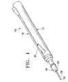
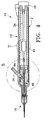
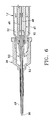
本発明のハンドピース10は、一般的に、ハンドピース本体12と作用チップ16とを含む。本体12は、一般的に、外部灌注チューブ18と吸引継手20とを含む。本体12は、当業で公知の水晶体超音波乳化吸引術ハンドピースに構造的に類似しており、および、プラスチック、チタン、ステンレススチールから作られてよい。図6において最も適切に理解できるように、作用チップ16は、チップ/キャップスリーブ26と、針28と、チューブ30とを含む。スリーブ26は、製品として入手可能な任意の適切な水晶体超音波乳化吸引術チップ/キャップスリーブであってよく、または、スリーブ26は、マルチルーメンチューブ(multi−lumen tube)のような他のチューブに中に組み込まれてもよい。針28は、Alcon Laboratories,Inc.(Fort Worth,Texas)から入手可能なTURBOSONICSチップのような、製品として入手可能な任意の中空の水晶体超音波乳化吸引術切断チップであってよい。チューブ30は、例えば29ゲージ皮下針管のような針28内に嵌合するのに適切な任意のサイズのチューブであってよい。
The
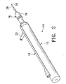
図5において最も適切に理解されるように、チューブ30はその遠位端部において自由であり、かつ、その近位端部においてポンプ吸引チャンバ42に連結されている。チューブ30とポンプ吸引チャンバ42は、シリコーンガスケット、ガラスフリット、または、銀はんだのような比較的高い融点を有する任意の適切な手段によって、流体耐密に密封されていてよい。継手44が吸引ホーン46内でチューブ30を保持する。穴48が継手20と連通し、この継手20は、ホーン46を通過して継手20の外に出る吸引通路を形成するように、ホーン46の中に軸支されてOリングシール50によって封止されている。ホーン46は、ポート54において灌注チューブ18と連通する灌注チューブ52を形成するように、Oリングシール56によって本体12内に保持されている。
As best seen in FIG. 5,
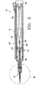
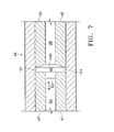
図7において最も適切に理解されるように、本発明の第1の実施形態では、ポンプ吸引チャンバ42は、電極45、47によってその両端部が封止されている比較的大きいポンプ吸引リザーバ43を収容する。電力が絶縁ワイヤ(図示されていない)によって電極45、47に供給される。使用時には、外科用流体(例えば、塩水灌注液)がポート55とチューブ34と逆止弁53とを通ってリザーバ43の中に入り、および、この逆止弁53は当業で公知である。電流(好ましくは、無線周波数交流電流すなわちRFAC)が、外科用流体の導電性のせいで電極45、47に供給されてその電極間に印加される。電流が外科用流体を通って流れると、その外科用流体が沸騰する。外科用流体が沸騰すると、その外科用流体は急速に膨張して、ポート57を通ってポンプ吸引チャンバ42の外に出てチューブ30の中に入る(逆止弁53がその膨張流体がチューブ34の中に入ることを防止する)。膨張する気泡が、チューブ30内の外科用流体をポンプ吸引チャンバ42の下流の方向に前方に押す。電流の後続のパルスが、外科用流体をチューブ30を下流の方向に移動させる連続した気泡を形成する。ポンプ吸引チャンバ42によって得られる流体パルスのサイズと圧力は、電極45、47に送られる電流パルスの長さ、タイミング、および/または、電力を変化させることによって、および、リザーバ43の寸法を変化させることによって変化させられることが可能である。これに加えて、外科用流体は、ポンプ吸引チャンバ42内に入る前に予熱されてもよい。外科用流体を予熱することは、ポンプ吸引チャンバ42によって必要とされる電力を減少させ、および/または、圧力パルスが発生させられることが可能な速度を増大させるだろう。
As best seen in FIG. 7, in the first embodiment of the present invention, the
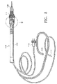
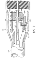
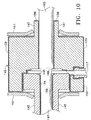
図8から図10において最も適切に理解されるように、本発明の第2の実施形態では、ハンドピース110は、一般的に、電力供給ケーブル113と、灌注/吸引管路115と、ポンプ吸引チャンバ供給管路117とを有する本体112を含む。ハンドピース110の遠位端部111は、電極145と電極147との間に形成されているリザーバ143を有するポンプ吸引チャンバ142を含む。電極145、147は、アルミニウム、チタン、炭素、または、他の同様に導電性の材料で作られており、および、電極145、147上に形成されている陽極酸化処理層159によって互いに電気的に絶縁されておりかつ本体112から電気的に絶縁されていることが好ましい。陽極酸化処理層159は未処理のアルミニウムよりも導電性が低く、したがって電気絶縁体として機能する。電極145、147と電気端子161、163は陽極酸化処理されておらず、したがって導電性である。層159は、当業で公知の任意の適切な陽極酸化処理方法によって形成されてよく、および、電極145、147と電気端子161、163は、剥き出しのアルミニウムを露出させるために、陽極酸化処理中にマスキングされるか、または、陽極酸化処理後に機械加工されてよい。電力は端子161、163とワイヤ149、151とをそれぞれに通して電極145、147に供給される。流体は供給管路117と逆止弁153とを通してリザーバ143に供給される。吸引チューブ167を同中心に取り囲む外側チューブ165がポンプ吸引チャンバ142から遠位方向に延びる。チューブ165、167はチューブ30に類似した構造であってよい。チューブ167はチューブ165よりも直径がわずかに小さく、それによってチューブ165とチューブ167との間に環状の通路すなわち間隙169を形成する。管状の間隙169はリザーバ143と流体連通する。
As best understood in FIGS. 8-10, in the second embodiment of the present invention, the
使用時には、外科用流体は供給管路117と逆止弁153とを通ってリザーバ143の中に入る。電流が、外科用流体の導電性のせいで電極145、147に供給されてその電極間に印加される。電流が外科用流体を通って流れると、その外科用流体が沸騰する。外科用流体が沸騰すると、この外科用流体は急速に膨張し、環状間隙169を通ってポンプ吸引チャンバ142の外に出る。この膨張する気泡が環状間隙169内の外科用流体をポンプ吸引チャンバ142の下流に向けて前方に押す。電流の後続のパルスが、環状間隙169の下流に向けて外科用流体を移動すなわち前進させる連続した気泡を形成する。
In use, surgical fluid enters
当業者は、図8から図10の番号付けが、図8から図10では各番号に「100」が追加されていることを除いて、図1から図7の番号付けと同一であることを認識するだろう。 Those skilled in the art will recognize that the numbering of FIGS. 8-10 is the same as the numbering of FIGS. 1-7 except that in FIGS. 8-10, “100” is added to each number. You will recognize.
図11から図13において最も適切に理解されるように、本発明の第3の実施形態では、ハンドピース210が、一般的に、電力供給ケーブル213と灌注/吸引管路215とポンプ吸引チャンバ供給管路217とを有する本体212を含む。ハンドピース210の遠位端部211が、電極245と電極247との間に形成されているリザーバ243を有するポンプ吸引チャンバ242を含む。電極245と電極247はアルミニウムで作られており、および、電極245、247上に形成されている陽極酸化処理層259によって互いに絶縁されかつ本体212に対して電気的に絶縁されていることが好ましい。陽極酸化処理層259は未処理アルミニウムよりも導電性が低く、したがって電気絶縁体として機能する。電極245、247と電気端子261、263は陽極酸化処理されておらず、したがって導電性である。層259は、当業で公知の任意の適切な陽極酸化処理方法で形成されてよく、および、電極245、247と電気端子261、263は、剥きだしのアルミニウムを露出させるために、陽極酸化処理中にマスキングされてもよく、または、陽極酸化処理後に機械加工されてもよい。電力は、端子261、263とワイヤ249、251とをそれぞれに通して電極245、247に供給される。流体が供給管路217と逆止弁253とを通してリザーバ243に供給される。吸引チューブ267を同中心に取り囲む外部チューブ256がポンプ吸引チャンバ242から遠位方向に延びる。チューブ265、267はチューブ30に類似した構造であってよい。チューブ267はチューブ265よりも直径がわずかに小さく、それによってチューブ265とチューブ267との間に環状の通路すなわち間隙269を形成する。環状間隙269はリザーバ243と流体連通する。
As best understood in FIGS. 11-13, in the third embodiment of the present invention, the
使用時には、外科用流体は供給管路217と逆止弁253とを通ってリザーバ243の中に入る。電流が、外科用流体の導電性のせいで電極245、247に供給されこの電極間に印加される。電流が外科用流体を通って流れると、その外科用流体が沸騰する。電流は、より小さい電極ギャップセクションからより大きい電極ギャップセクションに流れ、すなわち、電気抵抗が最も低い区域から電気抵抗がより高い区域に流れる。沸騰波頭も電極247のより小さい端部からより大きい端部に進む。外科用流体が沸騰すると、この外科用流体は急速に膨張し、環状間隙269を通ってポンプ吸引チャンバ242の外に出る。この膨張する気泡が環状間隙269内の外科用流体をポンプ吸引チャンバ242の下流に向けて前方に押す。電流の後続のパルスが、環状間隙269の下流に向けて外科用流体を移動すなわち前進させる連続した気泡を形成する。
In use, surgical fluid enters
当業者は、図11から図13の番号付けが、図11から図13では各番号に「200」が追加されていることを除いて、図1から図7の番号付けと同一であることを認識するだろう。 Those skilled in the art will recognize that the numbering of FIGS. 11-13 is identical to the numbering of FIGS. 1-7 except that in FIGS. 11-13, “200” is added to each number. You will recognize.
本発明のハンドピースの幾つか実施形態が開示されているが、適切な圧力パルス力(pressure pulse force)と、温度と、立上り時間と、周波数とを生じさせる任意のハンドピースが使用されてよい。例えば、1グラム/秒から20,000グラム/秒の立上り時間と、1Hzから200Hzの周波数(10Hzから100Hzが最も好ましい)とを伴って、0.02グラムから20.0グラムの圧力パルス力を生じさせる任意のハンドピースが使用されてよい。圧力パルス力と周波数は、除去される材料の硬さの応じて様々であってよい。例えば、本発明者は、より高いパルス力を伴ったより低い周波数が、比較的硬い核材料を破砕して取り除く場合に最も効率的であり、および、より高い周波数とより低いパルス力とがより柔らかい核外の皮質材料を除去するのに有効であることを発見している。注入圧と、吸引流量と、真空限界(vacuum limit)は、現行の水晶体超音波乳化吸引術と同様である。 Although several embodiments of the handpiece of the present invention are disclosed, any handpiece that produces a suitable pressure pulse force, temperature, rise time, and frequency may be used. . For example, a pressure pulse force of 0.02 grams to 20.0 grams with a rise time of 1 gram / second to 20,000 grams / second and a frequency of 1 Hz to 200 Hz (10 Hz to 100 Hz is most preferred). Any handpiece that results can be used. The pressure pulse force and frequency may vary depending on the hardness of the material being removed. For example, the inventors have found that lower frequencies with higher pulse forces are most efficient when crushing and removing relatively hard nuclear material, and higher frequencies and lower pulse forces are softer It has been found effective in removing extranuclear cortical material. The injection pressure, the suction flow rate, and the vacuum limit are the same as those of the current phacoemulsification aspiration.
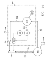
図10から理解されるように、ハンドピース310の操作に使用するための制御システム300の一実施形態が、制御モジュール347と、電力利得RF増幅器312と、関数発生器314とを含む。電力は直流電源316によってRF増幅器312に供給され、この直流電源316は、数百ボルト(典型的には±200ボルト)で動作する絶縁された直流電源であることが好ましい。制御モジュール347は、任意の適切なマイクロプロセッサ、マイクロコントローラ、コンピュータ、または、ディジタル論理コントローラであってよく、および、オペレータ入力装置318から入力を受け取ることができる。関数発生器314は、キロヘルツ単位の電気波形を増幅器312に供給し、および、典型的には、腐食を最小限にすることを補助するために約450KHz以上で動作する。
As can be seen from FIG. 10, one embodiment of a
使用時には、制御モジュール347は外科用操作卓320から入力を受け取る。操作卓320は、Alcon Laboratories,Inc.(Fort Worth,Texas)から入手可能なLEGACY(登録商標)SERIES TWENTY THOUSAND(登録商標)外科用システムのような製品として入手可能な任意の外科用制御操作卓であってよい。操作卓320は灌注管路322と吸引管路324とを経由してハンドピース310に連絡されており、および、管路322、324を通過する流れがフットスイッチ326を介してユーザによって制御される。ハンドピース310における灌注および吸引流量の情報は、インタフェース328を経由して操作卓320によって制御モジュール347に提供され、および、このインタフェース328は操作卓320上の超音波ハンドピース制御ポートまたは他の任意の出力ポートに接続されてよい。制御モジュール347は、制御卓320によって提供されるフットスイッチ326情報と、入力装置318からのオペレータ入力とを使用して、2つの制御信号330、332を生成する。信号322はピンチ弁334を操作するために使用され、このピンチ弁は流体源336からハンドピース310へ流れる外科用流体を調整する。流体源336からの流体は本明細書で説明する仕方で加熱される。信号330は関数発生器314を制御するために使用される。信号330に基づいて、関数発生器314は、外科用流体の加熱された加圧パルスを生じさせるためにハンドピース310に対して出力される電力波形を前進させるように増幅される、RF増幅器312に対してフットスイッチ326の位置によって決定されるオペレータによって選択された周波数および振幅で波形を提供する。
In use, the
幾つかの方法のどれかが、眼球の中に送り込まれる熱の量を制限するために使用されることが可能である。例えば、加熱された溶液のパルス列デューティサイクルが、眼球の中に送り込まれる加熱流体の総熱量がパルス周波数に応じて変化することがないように、パルス周波数に応じて変化させられることが可能である。この代わりに、吸引流量が、パルス周波数の増大に比例して吸引流量が増大するように、パルス周波数に応じて変化させられることが可能である。 Any of several methods can be used to limit the amount of heat delivered into the eyeball. For example, the pulse train duty cycle of the heated solution can be varied according to the pulse frequency so that the total heat of the heated fluid delivered into the eyeball does not vary according to the pulse frequency. . Alternatively, the suction flow rate can be varied depending on the pulse frequency so that the suction flow rate increases in proportion to the increase in pulse frequency.
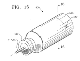
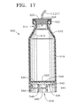
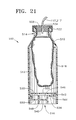
図15から図18は、眼科用外科用ハンドピースに対する外科用流体の配送のための容器500の好ましい実施形態を示す。容器500は、液化破砕ハンドピース10、110、210、310のような液化破砕ハンドピースに外科用流体を配送するものとして本明細書で説明されている。しかし、容器500は、さらに、耳の手術または鼻の手術で使用される外科用ハンドピースのような他の外科用ハンドピースと共に使用されてもよい。容器500は、図14における流体源336によって表されている。容器500の底部516は、外科用操作卓320の入れ物(図19、20)に取り外し自在に係合するように設計されている。
FIGS. 15-18 illustrate a preferred embodiment of a
容器500は、第1の部分すなわち本体510と、第1の部分510内に配置されている第2の部分すなわち変形可能なライナ512とを有する従来通りの多層プラスチック瓶であることが好ましい。第2の部分512は、第1の部分510から分離可能である変形可能なプラスチックで形成されていることが好ましい。一例を示すと、第2の部分512はナイロンで作られてもよい。別の例としては、第2の部分512は、互いの層の間に接着剤を伴ってエチレン酸化ビニルの外側層に結合されているポリプロピレンの内側層で形成されてもよい。第1の部分510は、第2の部分512を形成するために使用されるプラスチックよりも堅いプラスチックで形成されていることが好ましい。一例を示すと、第1の部分510は高密度ポリエチレンで形成されてもよい。別の例として、第1の部分510はポリプロピレンで形成されてもよい。容器500は従来通りの射出成形プロセスを使用して形成されることが好ましい。この代わりに、第1の部分510は、ステンレススチールまたは他の比較的堅い非プラスチック材料で形成されてもよく、および、第2の部分512は、プラスチック以外の変形可能な材料で形成されてもよい。
The
第1の部分510は、一般的に、開口514と、側壁518と、第1の横壁530と、第2の横壁536とを含む。第1の横壁530は穴520を伴う形で形成されている。容器500は、さらに、口514に固定されてもよいキャップ522も有することが好ましい。キャップ522はアルミニウムで作られていることが好ましく、および、口514に圧着されることが好ましい。この代わりに、キャップ522は糸(図示されていない)によって口514に固定されてもよい。キャップ522は、ポンプ吸引チャンバ供給管路117、217を封止状に受け入れるように設計されている、貫通穴524を有するゴム栓523を含むことが好ましい。この代わりに、第1の部分510の口514はゴム栓523だけによって封止されてもよい。
The
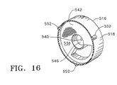
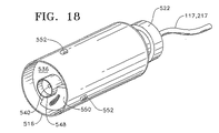
第2の横壁536は、容器500の中央に配置されていることが好ましい穴540と、第1の側部542と、第2の側部544とを含むことが好ましい。第1の側部542は、さらに、凹んだ体積546を含むことが好ましい。第2の側部544は、環状スカート548と少なくとも1つの隆起表面550とを含むことが好ましい。図16と図18とに最も適切に示されているように、隆起表面550は約120度の円弧長さを有することが好ましい。第2の横壁536の第2の側部544は、容器500内に保持されている外科用流体の特定の種類を識別するために、および、さらには、容器500が入れ物508の中に係合しているかどうかを識別するために使用されることが可能なパターンを形成する。これらの図には示されていないが、第2の側部544は、隆起表面550なしで作られてもよいし、または、複数の隆起表面550の様々な組み合わせを伴って形成されてもよい。例えば、2つの隆起表面550が240度の連続した隆起表面を形成してもよい。別の例としては、3つの隆起表面550が360度の連続した隆起表面を形成してもよい。隆起表面550の120度の円弧長さと、穴540の周囲の採用可能な角位置とを考慮して、第2の横壁536の第2の側部544が、7つの特有な隆起表面パターンを有する形で形成されてよいということを当業者は理解するだろう。このパターンの各々は2値信号(例えば、001、011、101、110、010、111、000)を表し、ここで「1」は隆起表面の存在を示し、かつ、「0」は隆起表面の不在を示す。当然のことながら、各々の隆起表面550に関して互いに異なる円弧長さが使用される場合には、第2の横壁536の第2の側部544は、7つよりも多いか少ない特有の隆起表面パターンを有する形に形成されてよい。3つの突出部552が、第1の横壁530の付近において側壁518の外側表面上に配置されている。突出部552は、穴540の周りに115度の間隔で互いに間隔を置いて配置されていることが好ましい。
The second
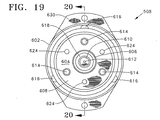
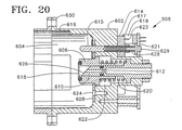
入れ物508は、一般的に、ハウジング602と、内部604と、ピストン606と、ピストン保持器608と、圧力突起すなわち圧力針610と、複数のセンサ614とを含む。内部604は容器500の底部516を受け入れる。内部604の内側表面は、容器500の突出部552と作動的に係合するための3つのスロット616を有する。スロット616の各々は「L」字形の形状を有することが好ましく、この「L」の1つの脚部は、90度よりも小さい距離にわたって内部604の内側表面の外周に沿って時計回り方向に延びる。ピストン606はその前端部にフェースシール(face seal)618を有し、および、空洞622内に配置されているばね620によって内部604から外向きに偏倚させられている。ピストン保持器608はピストン606を内部604内に固定し、および、ねじ624によってハウジング602に固定されている。圧力突起610は、鋭い先端626と、外科用操作卓320内の加圧流体(例えば、加圧空気)源に流体連結しているルーメン612とを有する。センサ614が、容器500の隆起表面550と作動的に係合するために圧力突起610の周りに120度の間隔で配置されていることが好ましい。各々のセンサ614は、ハウジング602の縦軸線に沿った移動が可能でありかつばね座629上に装着されているばね628によって外方に偏倚させられているプランジャ615と、プランジャ615に連結されているフィン(fin)617と、プリント回路基板621上に取り付けられている光センサ619とを含むことが好ましい。光路すなわち光信号(例えば、光のビーム)が、光センサ619の2重の穴623を経由してセンサ614を横切って形成される。センサ614に適している例示的な光センサ619が、Omron Sensorsから入手可能なEESJ3G遮断センサ(interruptive sensor)である。この代わりに、センサ614は、プランジャ615の撓みすなわち撓み力を測定する従来のフォースレジスティブセンサ(force resistive sensor)であってもよい。こうしたフォースレジスティブセンサは、フィン617と光センサ619とプリント回路基板621とを含まない形で形成されてよい。入れ物508は取り付けブラケット630を介して外科用操作卓320内に取り付けられている。
The
ユーザが突出部552をスロット616と位置合わせし、容器500の底部516をスライドさせて内部604の中に入れ、その次に容器500を時計回り方向に回転させると、容器500は入れ物508の中に取り外し自在に固定される。これと同時に、環状スカート548の内側表面がピストン606の外側表面に係合し、および、ピストン606が空洞622の中を通って内方に移動し、圧力突起610が第2の横壁536の穴540に係合することを可能にする。凹んだ体積546が、圧力突起610が第1の横壁530に接触すること、または、それが外科用流体を保持する第2の部分512に穿孔することを防止する。隆起表面550を含む第2の横壁536の第2の側部544の一部分において、対応するセンサ614のプランジャ615が押し下げられる。隆起表面550が存在しない場合には、対応するセンサ614のプランジャ615は押し下げられないか、または、その代わりに、隆起表面550が存在する場合には、より少ない量だけ押し下げられる。センサ614のプランジャ615が押し下げられる時には、フィン617が光センサ619の2重の穴623の間を動いて、センサ619の光路を中断する。押し下げられるプランジャ615を有するセンサ614の各々は協働して、プリント回路基板621を経由して外科用操作卓320に伝送される第2の横壁536の第2の側部544上の隆起表面550の固有のパターンを表す2値電気信号を生成する。外科用操作卓320の制御モジュール347は、特定の属性(例えば、粘度、外科用流体供給圧力)を有する特定の外科用流体にこうした電気信号を関連付けるようにプログラムされてよい。これに加えて、制御モジュール347は、外科用流体供給圧力や、制御システム300、外科用操作卓320、または、液化破砕ハンドピース10、110、210、310の他の動作パラメータを、個々の外科用流体に応じて自動的に変更または調整することができる。
When the user aligns the
上述したように容器500が入れ物508内に係合させられると、容器500からの外科用流体が、後述の好ましい仕方で液化破砕ハンドピース210に送られる。加圧空気が、圧力突起610のルーメン612から、第2の横壁536の穴540を通して、および、第1の横壁530の穴520を通して配送される。図21に最も適切に示されているように、加圧空気は、第2の部分512の外側表面と第1の部分510の内側表面との間の空間の中に入り、第1の部分510から第2の部分512を分離させ、および、少なくとも部分的に第2の部分512を押しつぶす。この加圧空気は、第2の部分512内から管217を通してハンドピース210に外科用流体を強制的に送り込む。
As described above, when the
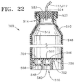
図22は、眼科用外科用ハンドピースに外科用流体を配送するための容器700の第2の好ましい実施形態を示す。容器700は、2つの横壁530、536の代わりに、側部704、706を有する単一の横壁702を有するということを除いて、図15から図18の容器500に実質的に類似している。第1の側部704は、第1の横壁530に実質的に類似した形状を有し、および、凹んだ体積546も含む。第2の側部706は、凹んだ体積546のない、第2の横壁536に実質的に類似した形状を有する。容器700は、容器500に関して上述した仕方と実質的に類似した仕方で、液化破砕ハンドピースに対して外科用流体を配送するように作られ使用されることが好ましい。
FIG. 22 illustrates a second preferred embodiment of a
上記から、本発明が、外科用流体を外科用ハンドピースに対して配送する単純で信頼性の高い装置と方法とを提供するということが理解されるだろう。本発明は、さらに、ハンドピースに対して供給されるべき特定の外科用流体を識別するための自動化された方法を提供する。 From the foregoing, it will be appreciated that the present invention provides a simple and reliable apparatus and method for delivering surgical fluid to a surgical handpiece. The present invention further provides an automated method for identifying a particular surgical fluid to be delivered to a handpiece.
本明細書において本発明は例示の形で説明され、および、様々な変更が当業者によって加えられてよい。例えば、容器500の第2の横壁536、または、容器700の横壁702の第2の側部706は、穴540なしで形成されてよい。この場合には、参照番号540は、容器500の縦軸線を示し、および、圧力突起610の鋭い先端626は第2の横壁536または横壁702に穿孔するように形成されてよい。
The invention is described herein in an illustrative manner and various modifications may be made by those skilled in the art. For example, the second
本発明の動作および構造が上述の説明から明らかであると考えられる。上記で示されまたは説明された装置と方法とが好ましいものとして特徴付けられているが、様々な変形と変更とが、後述の特許請求項で定義されている通りの本発明の着想と範囲とから逸脱することなしに、これらに加えられることが可能である。 The operation and structure of the present invention will be apparent from the above description. Although the devices and methods shown or described above are characterized as preferred, various modifications and changes may be made to the spirit and scope of the invention as defined in the following claims. It is possible to add to these without departing from.
Claims (34)
変形可能な材料で作られており、かつ、閉鎖端部と、開放端部と、外側表面と、外科用ハンドピースに対する配送のための外科用流体を受け入れるための第1の体積とを有する第1の部分と、
前記変形可能な材料よりも堅い材料で作られており、かつ、第1の端部と、第2の端部と、外側表面と、内側表面と、第1の横壁と、第2の横壁と、前記第1の部分を受け入れる第2の体積とを有する第2の部分であって、前記第1の端部は、前記外科用流体の配送のための出口を有し、前記第1の横壁は、前記第1の部分の前記外側表面と前記第2の部分の前記内側表面との間に加圧流体を受け入れるための穴を有し、前記第2の横壁は第1の側部と第2の側部とを有し、前記第2の横壁の前記第2の側部は、前記加圧流体の供給源が前記穴と流体連通しているように前記加圧流体の前記供給源に取り外し自在に係合するための区域を有する第2の部分と、
を備える容器。 A container for delivery of surgical fluid to a surgical handpiece,
A first made of a deformable material and having a closed end, an open end, an outer surface, and a first volume for receiving a surgical fluid for delivery to the surgical handpiece. 1 part and
Made of a material stiffer than the deformable material and having a first end, a second end, an outer surface, an inner surface, a first lateral wall, and a second lateral wall; A second portion having a second volume for receiving the first portion, the first end having an outlet for delivery of the surgical fluid and the first lateral wall Has a hole for receiving pressurized fluid between the outer surface of the first portion and the inner surface of the second portion, and the second lateral wall has a first side portion and a first side portion. And the second side of the second lateral wall is connected to the source of pressurized fluid such that the source of pressurized fluid is in fluid communication with the hole. A second portion having an area for releasably engaging;
Container.
前記栓の中に封止状に配置されており、かつ、前記第1の体積と流体連通している管と、
をさらに備える請求項1に記載の容器。 A stopper disposed in the outlet of the second portion;
A tube disposed in a sealed manner in the plug and in fluid communication with the first volume;
The container according to claim 1, further comprising:
変形可能な材料で作られており、かつ、閉鎖端部と、開放端部と、外側表面と、外科用ハンドピースに対する配送のための外科用流体を受け入れる第1の体積とを有する第1の部分と、
前記変形可能な材料よりも堅い材料で作られており、かつ、第1の端部と、第2の端部と、外側表面と、内側表面と、第1の側部と第2の側部とを有する横壁と、前記第1の部分を受け入れる第2の体積とを有する第2の部分であって、前記第1の端部は、前記外科用流体の配送のための出口を有し、前記横壁の前記第1の側部は、前記第1の部分の前記外側表面と前記第2の部分の前記内側表面との間に加圧流体を受け入れるための穴を有し、前記横壁の前記第2の側部は、前記加圧流体の供給源が前記穴と流体連通しているように前記加圧流体の前記供給源に取り外し自在に係合するための区域を有する第2の部分と、
を備える容器。 A container for delivery of surgical fluid to a surgical handpiece,
A first made of a deformable material and having a closed end, an open end, an outer surface, and a first volume that receives surgical fluid for delivery to the surgical handpiece Part,
Made of a material stiffer than the deformable material and having a first end, a second end, an outer surface, an inner surface, a first side and a second side And a second portion having a second volume for receiving the first portion, the first end having an outlet for delivery of the surgical fluid; The first side of the lateral wall has a hole for receiving pressurized fluid between the outer surface of the first portion and the inner surface of the second portion; A second side having a section for releasably engaging the source of pressurized fluid such that the source of pressurized fluid is in fluid communication with the hole; ,
Container.
前記栓の中に封止状に配置されており、かつ、前記第1の体積と流体連通している管と、
をさらに備える請求項9に記載の容器。 A stopper disposed in the outlet of the second portion;
A tube disposed in a sealed manner in the plug and in fluid communication with the first volume;
The container according to claim 9, further comprising:
外科用ハンドピースに対する配送のための外科用流体を受け入れる第1の体積を有すする変形可能なライナと、
前記変形可能なライナを受け入れる第2の体積と、開口と、貫通する形で配置されている穴を有する第1の横壁と、第1および第2の側部を有する第2の横壁とを有する本体であって、前記第2の横壁の前記第2の側部は、前記穴と、前記本体と前記ライナとの間の空間とに加圧流体の供給源が流体連通しているように、前記加圧流体の前記供給源に取り外し自在に係合するための区域を有する本体と、
を備える容器。 A container for delivery of surgical fluid to a surgical handpiece,
A deformable liner having a first volume for receiving surgical fluid for delivery to the surgical handpiece;
A second volume for receiving the deformable liner, an opening, a first lateral wall having a hole disposed therethrough, and a second lateral wall having first and second sides. A main body, wherein the second side of the second lateral wall is in fluid communication with a source of pressurized fluid in the hole and a space between the main body and the liner, A body having an area for releasably engaging the source of the pressurized fluid;
Container.
外科用ハンドピースに対する配送のための外科用流体を受け入れる第1の体積を有する変形可能なライナと、
前記変形可能なライナを受け入れる第2の体積と、開口と、第1の側部と第2の側部と貫通する形で配置されている穴とを有する横壁とを有する本体であって、前記横壁の前記第2の側部は、前記穴と、前記本体と前記ライナとの間の空間とに加圧流体の供給源が流体連通しているように、前記加圧流体の前記供給源に取り外し自在に係合するための区域を有する本体と、
を備える容器。 A container for delivery of surgical fluid to a surgical handpiece,
A deformable liner having a first volume for receiving a surgical fluid for delivery to the surgical handpiece;
A body having a second volume for receiving the deformable liner, an opening, and a lateral wall having a first side and a hole disposed through the second side; The second side of the lateral wall communicates with the source of pressurized fluid such that a source of pressurized fluid is in fluid communication with the hole and a space between the body and the liner. A body having an area for releasably engaging;
Container.
ポンプ吸引チャンバを有する液化破砕ハンドピースと、
容器であって、
変形可能な材料で作られており、かつ、閉鎖端部と、開放端部と、外側表面と、外科用ハンドピースに対する配送のための外科用流体を受け入れる第1の体積とを有する第1の部分と、
前記変形可能な材料よりも堅い材料で作られており、かつ、第1の端部と、第2の端部と、外側表面と、内側表面と、第1の横壁と、第2の横壁と、前記第1の部分を受け入れる第2の体積とを有する第2の部分であって、前記第1の端部は、前記外科用流体の配送のための出口を有し、前記第1の横壁は、前記第1の部分の前記外側表面と前記第2の部分の前記内側表面との間に加圧流体を受け入れるための穴を有し、前記第2の横壁は第1および第2の側部を有し、前記第2の横壁の前記第2の側部は、前記加圧流体の供給源が前記穴と流体連通しているように前記加圧流体の前記供給源に取り外し自在に係合するための区域を有する第2の部分と、
を備える容器と、
前記加圧流体の前記供給源を含み、かつ、前記容器を取り外し自在に受け入れるための入れ物を有する外科用操作卓であって、前記入れ物は、前記加圧流体の前記供給源を前記第2の横壁の前記第2の側部の前記区域と流体連結するためのルーメンを有する外科用操作卓と、
前記第2の部分の前記出口を前記液化破砕ハンドピースと流体連結する管と、
を備えていて;
それによって、前記外科用操作卓が前記ルーメンからの前記加圧流体を提供する時に、前記加圧流体は、前記穴を通り、前記第1の部分の前記外側表面と前記第2の部分の前記内側表面との間を通って流れ、および、前記外科用流体は前記管によって前記ポンプ吸引チャンバに配送される;
システム。 A system for delivering surgical fluid to a liquefaction crushing handpiece,
A liquefied crushing handpiece having a pump suction chamber;
A container,
A first made of a deformable material and having a closed end, an open end, an outer surface, and a first volume that receives surgical fluid for delivery to the surgical handpiece Part,
Made of a material stiffer than the deformable material and having a first end, a second end, an outer surface, an inner surface, a first lateral wall, and a second lateral wall; A second portion having a second volume for receiving the first portion, the first end having an outlet for delivery of the surgical fluid and the first lateral wall Has a hole for receiving pressurized fluid between the outer surface of the first portion and the inner surface of the second portion, the second lateral wall being on the first and second sides And the second side of the second lateral wall is removably engaged with the source of pressurized fluid such that the source of pressurized fluid is in fluid communication with the hole. A second part having an area for joining;
A container comprising:
A surgical console including the source of the pressurized fluid and having a receptacle for removably receiving the container, wherein the receptacle directs the source of the pressurized fluid to the second A surgical console having a lumen for fluid communication with the section on the second side of the transverse wall;
A tube fluidly connecting the outlet of the second part with the liquefaction crushing handpiece;
With;
Thereby, when the surgical console provides the pressurized fluid from the lumen, the pressurized fluid passes through the hole and the outer surface of the first portion and the second portion of the second portion. Flowing between the inner surface and the surgical fluid is delivered to the pump suction chamber by the tube;
system.
ポンプ吸引チャンバを有する液化破砕ハンドピースと、
容器であって、
変形可能な材料で作られており、かつ、閉鎖端部と、開放端部と、外側表面と、外科用ハンドピースに対する配送のための外科用流体を受け入れる第1の体積とを有する第1の部分と、
前記変形可能な材料よりも堅い材料で作られており、かつ、第1の端部と、第2の端部と、外側表面と、内側表面と、第1の側部と第2の側部とを有する横壁と、前記第1の部分を受け入れる第2の体積とを有する第2の部分であって、前記第1の端部は、前記外科用流体の配送のための出口を有し、前記横壁の前記第1の側部は、前記第1の部分の前記外側表面と前記第2の部分の前記内側表面との間に加圧流体を受け入れるための穴を有し、前記横壁の前記第2の側部は、前記加圧流体の供給源が前記穴と流体連通しているように前記加圧流体の前記供給源に取り外し自在に係合するための区域を有する第2の部分と、
を備える容器と、
前記加圧流体の前記供給源を含み、かつ、前記容器を取り外し自在に受け入れるための入れ物を有する外科用操作卓であって、前記入れ物は、前記加圧流体の前記供給源を前記横壁の前記第2の側部の前記区域と流体連結するためのルーメンを有する外科用操作卓と、
前記第2の部分の前記出口を前記液化破砕ハンドピースと流体連結する管と、
を備えていて、
それによって、前記外科用操作卓が前記ルーメンからの前記加圧流体を提供する時に、前記加圧流体は、前記穴を通り、前記第1の部分の前記外側表面と前記第2の部分の前記内側表面との間を通って流れ、および、前記外科用流体は前記管によって前記ポンプ吸引チャンバに配送される、
システム。 A system for delivering surgical fluid to a liquefaction crushing handpiece,
A liquefied crushing handpiece having a pump suction chamber;
A container,
A first made of a deformable material and having a closed end, an open end, an outer surface, and a first volume that receives surgical fluid for delivery to the surgical handpiece Part,
Made of a material stiffer than the deformable material and having a first end, a second end, an outer surface, an inner surface, a first side and a second side And a second portion having a second volume for receiving the first portion, the first end having an outlet for delivery of the surgical fluid; The first side of the lateral wall has a hole for receiving pressurized fluid between the outer surface of the first portion and the inner surface of the second portion; A second side having a section for releasably engaging the source of pressurized fluid such that the source of pressurized fluid is in fluid communication with the hole; ,
A container comprising:
A surgical console including the source of pressurized fluid and having a receptacle for removably receiving the container, wherein the receptacle directs the source of pressurized fluid to the side wall. A surgical console having a lumen for fluid communication with said section on a second side;
A tube fluidly connecting the outlet of the second part with the liquefaction crushing handpiece;
With
Thereby, when the surgical console provides the pressurized fluid from the lumen, the pressurized fluid passes through the hole and the outer surface of the first portion and the second portion of the second portion. Flowing between the inner surface and the surgical fluid is delivered by the tube to the pump suction chamber;
system.
Applications Claiming Priority (2)
| Application Number | Priority Date | Filing Date | Title |
|---|---|---|---|
| US10/212,619 US7160268B2 (en) | 2002-08-05 | 2002-08-05 | Container for delivery of fluid to ophthalmic surgical handpiece |
| PCT/US2003/022909 WO2004012637A1 (en) | 2002-08-05 | 2003-07-23 | Container for delivery of fluid to ophthalmic surgical handpiece |
Publications (1)
| Publication Number | Publication Date |
|---|---|
| JP2005534412A true JP2005534412A (en) | 2005-11-17 |
Family
ID=31187808
Family Applications (1)
| Application Number | Title | Priority Date | Filing Date |
|---|---|---|---|
| JP2004526134A Pending JP2005534412A (en) | 2002-08-05 | 2003-07-23 | Container for delivering fluid to an ophthalmic surgical handpiece |
Country Status (12)
| Country | Link |
|---|---|
| US (1) | US7160268B2 (en) |
| EP (1) | EP1553902B1 (en) |
| JP (1) | JP2005534412A (en) |
| AR (1) | AR040736A1 (en) |
| AT (1) | ATE432058T1 (en) |
| AU (1) | AU2003256669B2 (en) |
| BR (1) | BR0313126A (en) |
| CA (1) | CA2490832A1 (en) |
| DE (1) | DE60327789D1 (en) |
| IL (1) | IL166077A (en) |
| MX (1) | MXPA05000605A (en) |
| WO (1) | WO2004012637A1 (en) |
Cited By (1)
| Publication number | Priority date | Publication date | Assignee | Title |
|---|---|---|---|---|
| JP2015517847A (en) * | 2012-04-26 | 2015-06-25 | アルコン リサーチ, リミテッド | Perfusion source identification system |
Families Citing this family (22)
| Publication number | Priority date | Publication date | Assignee | Title |
|---|---|---|---|---|
| WO2004073546A2 (en) * | 2003-02-14 | 2004-09-02 | Alcon, Inc., | Apparatus and method for determining that a surgical fluid container is near empty |
| WO2004073751A2 (en) * | 2003-02-14 | 2004-09-02 | Alcon, Inc. | Apparatus and method for determining that a surgical fluid container is near empty |
| US7758585B2 (en) * | 2005-03-16 | 2010-07-20 | Alcon, Inc. | Pumping chamber for a liquefaction handpiece |
| US20060212037A1 (en) * | 2005-03-16 | 2006-09-21 | Alcon, Inc. | Pumping chamber for a liquefaction handpiece |
| US8043300B2 (en) * | 2005-07-05 | 2011-10-25 | Alcon, Inc. | Handpiece tip assembly |
| ATE456354T1 (en) * | 2005-09-29 | 2010-02-15 | Alcon Inc | DOUBLE CHAMBER PACKAGING SYSTEM FOR SOLUTIONS |
| US7540855B2 (en) * | 2007-06-01 | 2009-06-02 | Peregrine Surgical, Ltd. | Disposable aspirator cassette |
| US20090032121A1 (en) * | 2007-07-31 | 2009-02-05 | Chon James Y | Check Valve |
| US7849875B2 (en) * | 2007-07-31 | 2010-12-14 | Alcon, Inc. | Check valve |
| US8291933B2 (en) * | 2008-09-25 | 2012-10-23 | Novartis Ag | Spring-less check valve for a handpiece |
| US8608696B1 (en) * | 2009-02-24 | 2013-12-17 | North Carolina State University | Rapid fluid cooling devices and methods for cooling fluids |
| US7833206B1 (en) | 2010-02-02 | 2010-11-16 | Peregrine Surgical, Ltd. | Method and apparatus for disposable aspirator cassette |
| US8689439B2 (en) | 2010-08-06 | 2014-04-08 | Abbott Laboratories | Method for forming a tube for use with a pump delivery system |
| US8377000B2 (en) | 2010-10-01 | 2013-02-19 | Abbott Laboratories | Enteral feeding apparatus having a feeding set |
| US8377001B2 (en) | 2010-10-01 | 2013-02-19 | Abbott Laboratories | Feeding set for a peristaltic pump system |
| USD699343S1 (en) | 2011-12-20 | 2014-02-11 | Alcon Research, Ltd. | Irrigation solution bag |
| DE102012204680B4 (en) * | 2012-03-23 | 2019-04-25 | Olympus Winter & Ibe Gmbh | Method and system for flushing solution supply during endoscopic procedures |
| US11667437B2 (en) * | 2017-09-08 | 2023-06-06 | Kysten Altenburg | Modeling clay container |
| CN110338969B (en) * | 2019-07-23 | 2024-03-12 | 以诺康医疗科技(苏州)有限公司 | Ultrasonic suction and liquid injection integrated instrument |
| US11679195B2 (en) | 2021-04-27 | 2023-06-20 | Contego Medical, Inc. | Thrombus aspiration system and methods for controlling blood loss |
| USD1089647S1 (en) | 2023-08-15 | 2025-08-19 | Alcon Inc. | Phacoemulsification handpiece |
| IL308721B2 (en) | 2023-11-20 | 2025-02-01 | Israel Aerospace Ind Ltd | Drill bit accessory |
Family Cites Families (67)
| Publication number | Priority date | Publication date | Assignee | Title |
|---|---|---|---|---|
| US566282A (en) * | 1896-08-18 | Atomizer | ||
| US2678764A (en) * | 1951-12-06 | 1954-05-18 | Emery Carpenter Container Comp | Accessory for use in filling lined containers |
| US2766907A (en) * | 1955-03-15 | 1956-10-16 | Robbins Instr Corp | Pressure infusion apparatus |
| NL145136C (en) * | 1967-07-25 | 1900-01-01 | ||
| US3595232A (en) * | 1968-08-19 | 1971-07-27 | Saul Leibinsohn | Nongravitational infusion assembly |
| US3780732A (en) * | 1968-08-19 | 1973-12-25 | S Leibinsoh | Non-gravitational infusion set |
| US3690318A (en) * | 1970-04-16 | 1972-09-12 | Bourns Inc | Apparatus for parenteral fluid infusion provided with variable flow control means |
| US3838794A (en) * | 1972-07-10 | 1974-10-01 | H Markham | Package for storing and dispensing liquids |
| US3940001A (en) * | 1972-10-06 | 1976-02-24 | Ethyl Corporation | Recyclable plastic containers |
| US3949753A (en) * | 1972-11-27 | 1976-04-13 | Rolf Dockhorn | Apparatus for supplying aseptic fluids |
| US4008830A (en) * | 1973-08-10 | 1977-02-22 | Philip Meshberg | Liquid dispenser using a non vented pump and a collapsible plastic bag |
| US3992003A (en) * | 1975-10-24 | 1976-11-16 | Visceglia Marco P | Aerosol container having sealed propellant means |
| US4090514A (en) * | 1976-10-22 | 1978-05-23 | Howard Helmut Hinck | Pressure infusion device |
| US4270533A (en) * | 1977-08-16 | 1981-06-02 | Andreas Joseph M | Multiple chamber container for delivering liquid under pressure |
| US4223676A (en) * | 1977-12-19 | 1980-09-23 | Cavitron Corporation | Ultrasonic aspirator |
| US4246902A (en) * | 1978-03-10 | 1981-01-27 | Miguel Martinez | Surgical cutting instrument |
| US4379453A (en) * | 1978-12-28 | 1983-04-12 | Baron Howard C | Infusion system with self-generating pressure assembly |
| US4301802A (en) * | 1980-03-17 | 1981-11-24 | Stanley Poler | Cauterizing tool for ophthalmological surgery |
| US4337769A (en) * | 1980-08-01 | 1982-07-06 | Baxter Travenol Laboratories, Inc. | Pressure infusion module |
| US4493694A (en) * | 1980-10-17 | 1985-01-15 | Cooper Lasersonics, Inc. | Surgical pre-aspirator |
| US4330066A (en) * | 1980-11-21 | 1982-05-18 | Robert Berliner | Receptacle with collapsible internal container |
| US4396382A (en) * | 1981-12-07 | 1983-08-02 | Travenol European Research And Development Centre | Multiple chamber system for peritoneal dialysis |
| US4507116A (en) * | 1982-04-22 | 1985-03-26 | Saul Leibinsohn | Apparatus for the induced infusion of a liquid from a flexible liquid bag |
| US4515583A (en) * | 1983-10-17 | 1985-05-07 | Coopervision, Inc. | Operative elliptical probe for ultrasonic surgical instrument and method of its use |
| US4609368A (en) * | 1984-08-22 | 1986-09-02 | Dotson Robert S Jun | Pneumatic ultrasonic surgical handpiece |
| US4589415A (en) * | 1984-08-31 | 1986-05-20 | Haaga John R | Method and system for fragmenting kidney stones |
| US4626243A (en) * | 1985-06-21 | 1986-12-02 | Applied Biomedical Corporation | Gravity-independent infusion system |
| US4922902A (en) * | 1986-05-19 | 1990-05-08 | Valleylab, Inc. | Method for removing cellular material with endoscopic ultrasonic aspirator |
| US5312018A (en) * | 1988-07-08 | 1994-05-17 | Evezich Paul D | Containing and dispensing device for flowable material having relatively rigid and deformable material containment portions |
| US4886055A (en) * | 1988-01-22 | 1989-12-12 | Hoppough John M | Nebulizer device |
| US4892230A (en) * | 1988-02-08 | 1990-01-09 | Lynn Jr Arthur E | Carbonated beverage bottle |
| US4821896A (en) * | 1988-03-24 | 1989-04-18 | Cheng Ping N | Nursing bottle with a liner and vent |
| US4869715A (en) * | 1988-04-21 | 1989-09-26 | Sherburne Fred S | Ultrasonic cone and method of construction |
| US4976707A (en) * | 1988-05-04 | 1990-12-11 | Sherwood Medical Company | Fluid collection, storage and infusion apparatus |
| US5060826A (en) | 1988-08-25 | 1991-10-29 | Fabricated Metals, Inc. | Container with inflatable vessel for controlling flow of liquid or viscous material |
| US4989583A (en) * | 1988-10-21 | 1991-02-05 | Nestle S.A. | Ultrasonic cutting tip assembly |
| US5013303A (en) * | 1988-11-03 | 1991-05-07 | Yehuda Tamari | Constant pressure infusion device |
| US5154694A (en) * | 1989-06-06 | 1992-10-13 | Kelman Charles D | Tissue scraper device for medical use |
| US5207638A (en) * | 1989-08-24 | 1993-05-04 | Hemotrans, Inc. | Blood transfer apparatus |
| WO1993002926A1 (en) * | 1991-08-05 | 1993-02-18 | Yoshino Kogyosho Co., Ltd. | Bottle of laminate structure and method of making said bottle |
| AU669715B2 (en) * | 1992-05-11 | 1996-06-20 | Yoshino Kogyosho Co., Ltd. | Laminated bottle and pump unit for laminated bottle |
| US5738657A (en) * | 1992-06-15 | 1998-04-14 | Abbott Laboratories | Ambulatory energized container system |
| JP2680510B2 (en) * | 1992-06-26 | 1997-11-19 | シャープ株式会社 | Cassette size detection mechanism |
| DE4332885A1 (en) * | 1992-09-28 | 1994-03-31 | Colgate Palmolive Co | Squeezable dispenser for toothpaste etc. - has inner flexible disposable container fitting into outer container and closed by cap and one-way locking valves |
| GB9227195D0 (en) * | 1992-12-16 | 1993-03-03 | Prior Francis G R | Bag |
| US5403276A (en) * | 1993-02-16 | 1995-04-04 | Danek Medical, Inc. | Apparatus for minimally invasive tissue removal |
| US5593028A (en) * | 1993-07-02 | 1997-01-14 | Habley Medical Technology Corporation | Multi-pharmaceutical storage, mixing and dispensing vial |
| US5431627A (en) * | 1993-11-12 | 1995-07-11 | Abbott Laboratories | Cassette identification system for use with a multi-program drug infusion pump |
| US5531697A (en) * | 1994-04-15 | 1996-07-02 | Sims Deltec, Inc. | Systems and methods for cassette identification for drug pumps |
| AU1433995A (en) * | 1993-12-28 | 1995-07-17 | Jaleh Shaban-Watson | Bottle with closure element for receiving a syringe |
| US5505708A (en) * | 1994-04-18 | 1996-04-09 | Atkinson; Carey J. | System for delivery of intravenous fluids and the like and the method of making thereof |
| US5497912A (en) * | 1994-10-20 | 1996-03-12 | Hoback; Michael W. | Disposable self-dispensing pressurized package for delivery of sterile fluids |
| US5810202A (en) * | 1994-10-20 | 1998-09-22 | Rick R. Wascher, P.C. | Disposable self-dispensing pressurized package for delivery of sterile fluids and solutions |
| US5616120A (en) * | 1995-02-06 | 1997-04-01 | Andrew; Mark S. | Method and apparatus for lenticular liquefaction and aspiration |
| CH691219A5 (en) * | 1995-10-26 | 2001-05-31 | Medtronic Electromedics Inc | Disposable filtration flexible bag. |
| US5899674A (en) * | 1995-12-01 | 1999-05-04 | Alcon Laboratories, Inc. | Indentification system for a surgical cassette |
| US6059544A (en) * | 1995-12-01 | 2000-05-09 | Alcon Laboratories, Inc. | Identification system for a surgical cassette |
| AUPO178796A0 (en) * | 1996-08-22 | 1996-09-12 | Oversby Pty Ltd | Intraocular irrigation/aspiration device |
| US5885243A (en) * | 1996-12-11 | 1999-03-23 | Alcon Laboratories, Inc. | Liquefaction handpiece |
| CA2230768C (en) * | 1997-02-28 | 2007-02-13 | John W. Safian | Multilayer container package |
| US6036458A (en) * | 1997-10-03 | 2000-03-14 | Allergan Sales, Inc. | Automated phaco pack bar code reader identification |
| IL123839A0 (en) * | 1998-03-26 | 1998-10-30 | Atad Dev & Medical Services Ltd | Pressurized intravenous infusion bag |
| US5989212A (en) * | 1998-06-04 | 1999-11-23 | Alcon Laboratories, Inc. | Pumping chamber for a liquefaction handpiece having a countersink electrode |
| US6206848B1 (en) * | 1998-06-04 | 2001-03-27 | Alcon Laboratories, Inc. | Liquefracture handpiece |
| US6276567B1 (en) * | 1999-03-29 | 2001-08-21 | Hydrus, Inc. | Pressurized fluid delivery apparatus |
| US6363932B1 (en) * | 2000-07-06 | 2002-04-02 | Clinical Technologies, Inc. | Aerosol enhancement device |
| US6561237B1 (en) * | 2000-11-28 | 2003-05-13 | Brasscorp Ltd. | Apparatus and method for urging fluid into a pressurized system |
-
2002
- 2002-08-05 US US10/212,619 patent/US7160268B2/en not_active Expired - Fee Related
-
2003
- 2003-07-23 CA CA002490832A patent/CA2490832A1/en not_active Abandoned
- 2003-07-23 JP JP2004526134A patent/JP2005534412A/en active Pending
- 2003-07-23 AT AT03766887T patent/ATE432058T1/en not_active IP Right Cessation
- 2003-07-23 WO PCT/US2003/022909 patent/WO2004012637A1/en not_active Ceased
- 2003-07-23 MX MXPA05000605A patent/MXPA05000605A/en active IP Right Grant
- 2003-07-23 DE DE60327789T patent/DE60327789D1/en not_active Expired - Fee Related
- 2003-07-23 AU AU2003256669A patent/AU2003256669B2/en not_active Expired - Fee Related
- 2003-07-23 BR BRPI0313126-2A patent/BR0313126A/en not_active IP Right Cessation
- 2003-07-23 EP EP03766887A patent/EP1553902B1/en not_active Expired - Lifetime
- 2003-07-30 AR AR20030102739A patent/AR040736A1/en unknown
-
2004
- 2004-12-30 IL IL166077A patent/IL166077A/en not_active IP Right Cessation
Cited By (1)
| Publication number | Priority date | Publication date | Assignee | Title |
|---|---|---|---|---|
| JP2015517847A (en) * | 2012-04-26 | 2015-06-25 | アルコン リサーチ, リミテッド | Perfusion source identification system |
Also Published As
| Publication number | Publication date |
|---|---|
| MXPA05000605A (en) | 2005-03-31 |
| IL166077A0 (en) | 2006-01-15 |
| EP1553902B1 (en) | 2009-05-27 |
| US7160268B2 (en) | 2007-01-09 |
| DE60327789D1 (en) | 2009-07-09 |
| EP1553902A1 (en) | 2005-07-20 |
| ATE432058T1 (en) | 2009-06-15 |
| AU2003256669A1 (en) | 2004-02-23 |
| IL166077A (en) | 2009-02-11 |
| WO2004012637A1 (en) | 2004-02-12 |
| AR040736A1 (en) | 2005-04-20 |
| US20040024380A1 (en) | 2004-02-05 |
| AU2003256669B2 (en) | 2008-12-04 |
| BR0313126A (en) | 2007-07-17 |
| CA2490832A1 (en) | 2004-02-12 |
Similar Documents
| Publication | Publication Date | Title |
|---|---|---|
| JP4394571B2 (en) | Device for delivering fluid to an ophthalmic surgical handpiece | |
| US7695447B2 (en) | Apparatus and method for determining that a surgical fluid container is near empty | |
| US20050228423A1 (en) | Apparatus and method for determining that a surgical fluid container is near empty | |
| JP2005534412A (en) | Container for delivering fluid to an ophthalmic surgical handpiece | |
| EP1199054B1 (en) | Liquefracture handpiece | |
| US6589204B1 (en) | Method of operating a liquefracture handpiece | |
| AU766987B2 (en) | Liquefracture handpiece | |
| EP1223902B1 (en) | Liquefracture handpiece | |
| US7276060B2 (en) | Surgical handpiece tip | |
| AU2003254195B2 (en) | Apparatus for delivery of fluid to ophthalmic surgical handpiece |
Legal Events
| Date | Code | Title | Description |
|---|---|---|---|
| A621 | Written request for application examination |
Free format text: JAPANESE INTERMEDIATE CODE: A621 Effective date: 20060116 |
|
| A131 | Notification of reasons for refusal |
Free format text: JAPANESE INTERMEDIATE CODE: A131 Effective date: 20090224 |
|
| A02 | Decision of refusal |
Free format text: JAPANESE INTERMEDIATE CODE: A02 Effective date: 20090825 |