JP2005532137A - Method and system for improving information content of image - Google Patents
Method and system for improving information content of image Download PDFInfo
- Publication number
- JP2005532137A JP2005532137A JP2004520990A JP2004520990A JP2005532137A JP 2005532137 A JP2005532137 A JP 2005532137A JP 2004520990 A JP2004520990 A JP 2004520990A JP 2004520990 A JP2004520990 A JP 2004520990A JP 2005532137 A JP2005532137 A JP 2005532137A
- Authority
- JP
- Japan
- Prior art keywords
- image
- motion
- images
- artifacts
- pet
- Prior art date
- Legal status (The legal status is an assumption and is not a legal conclusion. Google has not performed a legal analysis and makes no representation as to the accuracy of the status listed.)
- Withdrawn
Links
- 238000000034 method Methods 0.000 title claims abstract description 90
- 230000033001 locomotion Effects 0.000 claims abstract description 253
- 238000003384 imaging method Methods 0.000 claims abstract description 26
- 238000012545 processing Methods 0.000 claims abstract description 22
- 238000004590 computer program Methods 0.000 claims abstract description 11
- 230000015572 biosynthetic process Effects 0.000 claims abstract description 9
- 238000007689 inspection Methods 0.000 claims description 3
- 238000002558 medical inspection Methods 0.000 claims 1
- 238000002603 single-photon emission computed tomography Methods 0.000 claims 1
- 238000002059 diagnostic imaging Methods 0.000 abstract description 4
- 238000002600 positron emission tomography Methods 0.000 description 57
- 238000002591 computed tomography Methods 0.000 description 33
- 230000006870 function Effects 0.000 description 26
- 230000005855 radiation Effects 0.000 description 15
- 230000000241 respiratory effect Effects 0.000 description 13
- 230000005540 biological transmission Effects 0.000 description 12
- 230000008569 process Effects 0.000 description 8
- 238000005259 measurement Methods 0.000 description 5
- 230000029058 respiratory gaseous exchange Effects 0.000 description 5
- 230000009466 transformation Effects 0.000 description 5
- 238000010586 diagram Methods 0.000 description 4
- 230000008901 benefit Effects 0.000 description 3
- 238000012937 correction Methods 0.000 description 3
- 230000004807 localization Effects 0.000 description 3
- 238000003325 tomography Methods 0.000 description 3
- 238000010521 absorption reaction Methods 0.000 description 2
- 230000002238 attenuated effect Effects 0.000 description 2
- 238000009206 nuclear medicine Methods 0.000 description 2
- 230000002285 radioactive effect Effects 0.000 description 2
- 230000000153 supplemental effect Effects 0.000 description 2
- 210000003484 anatomy Anatomy 0.000 description 1
- 230000008859 change Effects 0.000 description 1
- 230000000295 complement effect Effects 0.000 description 1
- 238000002247 constant time method Methods 0.000 description 1
- 238000010276 construction Methods 0.000 description 1
- 238000013481 data capture Methods 0.000 description 1
- 230000000694 effects Effects 0.000 description 1
- 238000011156 evaluation Methods 0.000 description 1
- 238000009472 formulation Methods 0.000 description 1
- 238000002347 injection Methods 0.000 description 1
- 239000007924 injection Substances 0.000 description 1
- 238000002595 magnetic resonance imaging Methods 0.000 description 1
- 230000002503 metabolic effect Effects 0.000 description 1
- 239000002207 metabolite Substances 0.000 description 1
- 239000000203 mixture Substances 0.000 description 1
- 230000003287 optical effect Effects 0.000 description 1
- 210000000056 organ Anatomy 0.000 description 1
- 230000000737 periodic effect Effects 0.000 description 1
- 238000003672 processing method Methods 0.000 description 1
- 238000000926 separation method Methods 0.000 description 1
- 238000012546 transfer Methods 0.000 description 1
- 238000002604 ultrasonography Methods 0.000 description 1
Images


Classifications
-
- G—PHYSICS
- G06—COMPUTING; CALCULATING OR COUNTING
- G06T—IMAGE DATA PROCESSING OR GENERATION, IN GENERAL
- G06T5/00—Image enhancement or restoration
- G06T5/50—Image enhancement or restoration by the use of more than one image, e.g. averaging, subtraction
-
- A—HUMAN NECESSITIES
- A61—MEDICAL OR VETERINARY SCIENCE; HYGIENE
- A61B—DIAGNOSIS; SURGERY; IDENTIFICATION
- A61B6/00—Apparatus for radiation diagnosis, e.g. combined with radiation therapy equipment
- A61B6/52—Devices using data or image processing specially adapted for radiation diagnosis
- A61B6/5258—Devices using data or image processing specially adapted for radiation diagnosis involving detection or reduction of artifacts or noise
- A61B6/5264—Devices using data or image processing specially adapted for radiation diagnosis involving detection or reduction of artifacts or noise due to motion
-
- G06T5/73—
-
- G—PHYSICS
- G06—COMPUTING; CALCULATING OR COUNTING
- G06T—IMAGE DATA PROCESSING OR GENERATION, IN GENERAL
- G06T7/00—Image analysis
- G06T7/20—Analysis of motion
-
- G—PHYSICS
- G06—COMPUTING; CALCULATING OR COUNTING
- G06T—IMAGE DATA PROCESSING OR GENERATION, IN GENERAL
- G06T2207/00—Indexing scheme for image analysis or image enhancement
- G06T2207/10—Image acquisition modality
- G06T2207/10072—Tomographic images
-
- G—PHYSICS
- G06—COMPUTING; CALCULATING OR COUNTING
- G06T—IMAGE DATA PROCESSING OR GENERATION, IN GENERAL
- G06T2207/00—Indexing scheme for image analysis or image enhancement
- G06T2207/20—Special algorithmic details
- G06T2207/20172—Image enhancement details
- G06T2207/20201—Motion blur correction
-
- G—PHYSICS
- G06—COMPUTING; CALCULATING OR COUNTING
- G06T—IMAGE DATA PROCESSING OR GENERATION, IN GENERAL
- G06T2207/00—Indexing scheme for image analysis or image enhancement
- G06T2207/30—Subject of image; Context of image processing
- G06T2207/30004—Biomedical image processing
Abstract
本発明は、動く対象の画像の情報内容が向上される方法に関連する。本発明はまた、かかる方法が実行されうるシステム、並びに、データ処理ユニットにかかる方法を実行させることを可能とするコンピュータプログラムに関連する。方法は、医用撮像システムの分野において特に使用される。本発明の方法によれば、まず、動く対象の第1の画像は第1の撮像方法によって捕捉され、この画像は対象の動きによって生ずるアーティファクトを含む。第2の撮像法によって捕捉され、動きの夫々の動き状態において対象を表わす2つの更なる画像から、画像処理又は画像形成段階において異なった方法で行われる動きモデルが形成され、第1の画像、又は、第1の画像及び2つの更なる画像から形成される組合せ画像が向上される。The present invention relates to a method in which the information content of a moving object image is improved. The invention also relates to a system in which such a method can be performed as well as a computer program that allows a data processing unit to perform such a method. The method is particularly used in the field of medical imaging systems. According to the method of the present invention, first a first image of a moving object is captured by a first imaging method, and this image contains artifacts caused by the movement of the object. From two additional images captured by the second imaging method and representing the object in each motion state of the motion, a motion model is formed that is performed in a different way in the image processing or image formation stage, the first image, Alternatively, the combined image formed from the first image and two further images is enhanced.
Description
本発明は、動く対象の画像の情報内容を向上する方法に関連する。本発明はまた、この種類の方法が実行されるシステム、及び、データ処理ユニットにかかる方法を実行させることを可能とするコンピュータプログラムに関連する。この方法は、医用撮像システムの分野で特に使用される。 The present invention relates to a method for improving the information content of an image of a moving object. The invention also relates to a system in which this type of method is performed and to a computer program that allows a data processing unit to perform the method. This method is particularly used in the field of medical imaging systems.
この種類の方法は、動く対象の画像が形成されるべきいかなる場合においても適用され、これらの画像はしばしば回避することができない動きアーティファクトを含む。結果として、対象は、通常はぼけて画像化され、従って観察者にとっては対象に関する不適切な情報を提供するだけである。動きアーティファクトは、特に、動く対象のスライス画像又は体積画像の場合は、利用可能でない画像をしばしば生じさせる。 This type of method is applied in any case where images of moving objects are to be formed, and these images often contain motion artifacts that cannot be avoided. As a result, the object is usually blurred and thus only provides inappropriate information about the object to the viewer. Motion artifacts often result in images that are not available, especially in the case of sliced or volumetric images of moving objects.
非特許文献1は、組合せ画像を形成するよう、PET法により取得され再構成され、動きアーティファクトを含む動く対象の画像が、CT法により取得され再構成された動く対象の更なる画像に重畳される方法を開示する。組合せ画像は、2つの個々の画像の、両方の画像に含まれる重大な相互間の類似性の情報を用いた特別な位置合わせによって形成される。PET画像は、物理的な状況のため、開示される方法では考慮に入れられておらず位置合わせ中に問題を生じさせるはっきりとした動きアーティファクトを含む。
本発明は、動きアーティファクトを含む画像の情報内容を高めることを目的とする。 The present invention aims to enhance the information content of an image including motion artifacts.
この目的は、本発明によれば、動く対象の動きアーティファクトを含む第1の画像から導出されうる画像内容を向上させる方法であって、
(a)出来る限り少ない動きアーティファクトを伴って夫々の動き状態での対象を表わす2つの更なる画像を用いる段階と、
(b)2つの動き状態間で動きを行っている間に対象によってとられる動き状態を特徴付ける動きモデルを決定する段階とを含む方法によって達成される。第1の画像は、投影から再構成されねばならないかもしれない。
This object is, according to the invention, a method for improving the image content that can be derived from a first image containing motion artifacts of a moving object,
(A) using two additional images representing the object in each motion state with as few motion artifacts as possible;
(B) determining a motion model that characterizes the motion state taken by the object while performing motion between the two motion states. The first image may have to be reconstructed from the projection.
対象の動きによる動きアーティファクトを含む動く対象の第1の画像がある。動きアーティファクトは、例えば、捕捉時間中により多く動いた対象ほど、対象は鮮鋭に画像化されないことの原因である。かかる動きアーティファクトは、捕捉に用いられる撮像方法の捕捉時間が動きと比較して長く、対象が捕捉中に動く場合に生じうる。「動き」という用語は、非常に広い意味で解釈されるべきである。対象は、例えば、非常に複雑な自然な動き(人間の心臓)又は単に線形の均一な動き(一定の速度で回転する球面)を行いうる。 There is a first image of a moving object that includes movement artifacts due to the movement of the object. Motion artifacts are the reason that, for example, objects that move more during the acquisition time are less sharply imaged. Such motion artifacts can occur when the capture method of the imaging method used for capture is long compared to motion and the object moves during capture. The term “movement” should be interpreted in a very broad sense. The object can, for example, perform very complex natural movements (human heart) or simply linear uniform movements (a sphere rotating at a constant speed).
更に、対象の少なくとも2つの更なる画像が必要とされる。これらの画像は夫々、対象の動きの夫々の状態を表わし、出来る限り動きアーティファクトがなく、動きの2つの状態は、第1の画像の捕捉中に対象によって行われる動きから発生する。或いは、表わされる動きの2つの状態は、対象によって異なる時点に行われた動きから発生するものでありえ、第1の画像の捕捉中に対象によって行われた動きと少なくともおおよそ同じである。動き状態を出来るだけ少ないアーティファクトを伴って画像化するために、捕捉時間は一般的には動きの持続時間と比較して短い。 In addition, at least two additional images of the object are required. Each of these images represents a respective state of the subject's motion, with as few motion artifacts as possible, and the two states of motion arise from the motion performed by the subject during capture of the first image. Alternatively, the two states of motion represented may arise from motions made at different times by the subject and are at least approximately the same as those made by the subject during the capture of the first image. In order to image the motion state with as few artifacts as possible, the acquisition time is generally short compared to the duration of the motion.
第1の画像の捕捉に使用されうる撮像法及び2つの更なる画像は同じものであっても異なるものであってもよい。全ての画像に対して共通の撮像方法が用いられる場合、第1の画像と2つの更なる画像の異なる特徴は、捕捉パラメータの異なる調整によって実現されうる。2つの異なる撮像法が用いられると、各撮像法は、対象の他の特徴を再現し、かかる異なった特徴の情報は、有利には後の段階において捕捉される。 The imaging method and the two additional images that can be used to capture the first image may be the same or different. If a common imaging method is used for all images, different features of the first image and the two further images can be realized by different adjustments of the acquisition parameters. When two different imaging methods are used, each imaging method reproduces other features of the object, and information on such different features is advantageously captured at a later stage.
また、動きの2つの状態間に動きを行っている間に対象がとる動き状態を特徴付ける対象の動きの動きモデルが決定される。特に、対象の複雑な自然な動きの場合、対象の個々の部分は動きの実行中に異なって動き、例えば、対象のいくつかの部分は短い距離だけ進行するのに対して、他の部分は長くおそらくは曲がった経路を辿る。動きの2つの状態のうちの一方から開始して、動きモデルは、一方の動き状態から他方の動き状態への動き中に対象の異なる部分の動作を示す。 Also, a motion model of the target motion that characterizes the motion state taken by the target while performing the motion between the two states of motion is determined. In particular, in the case of complex natural movements of the object, the individual parts of the object move differently during the movement, for example, some parts of the object travel a short distance while other parts Follow a long, possibly curved path. Starting from one of the two states of motion, the motion model shows the behavior of different parts of the object during movement from one motion state to the other.
このように対象の動きに関して得られる情報は、補足的な画像処理又は画像形成段階中に様々な方法で組み込まれることができ、より高い質の結果としての画像が得られる。 Information obtained in this way about the movement of the object can be incorporated in various ways during the supplemental image processing or image formation stage, resulting in a higher quality resulting image.
例えば、請求項1に記載のような本発明によるかかる捕捉的な段階は、
(c)動きモデル及び2つの更なる画像から、対象が動きを行なったかのように少なくともおおよそ対象を表わす中間画像を形成する段階と、
(d)中間画像及び第1の画像から組合せ画像を形成する段階とである。
For example, such a capturing step according to the invention as claimed in
(C) forming from the motion model and two further images an intermediate image representing at least approximately the object as if the object had moved;
(D) forming a combined image from the intermediate image and the first image.
形成される中間画像は、動きを行うかのように対象を表わす。このために、動きの2つの既知の状態から開始して、対象の動きは、動きモデルによって模倣され、中間画像は例えば重畳によりこの情報から形成される。このように再構成された中間画像は、第1の画像とほぼ同じ動きアーティファクトを伴って対象を表わす。 The formed intermediate image represents the object as if it were moving. For this, starting from two known states of motion, the motion of the object is imitated by a motion model and an intermediate image is formed from this information, for example by superposition. The intermediate image reconstructed in this way represents the object with substantially the same motion artifact as the first image.
観察者は、第1の画像を、そこに含まれる動きアーティファクトに関わらず出来る限り少ない偽り(falsification)で見ることを望むことがあり、なぜならば情報は公知の画像処理法の間に失われうるからである。組合せ画像を形成するための中間画像と第1の画像の重畳は、一方では第1の画像が出来る限り少ない偽りで提示されること、他方では2つの更なる画像からの情報が、第1の画像の情報と直接組み合わされうるよう中間画像中に準備されること、という利点を与える。 An observer may wish to view the first image with as little falsification as possible regardless of the motion artifacts contained therein, because information can be lost during known image processing methods. Because. The superimposition of the intermediate image and the first image to form a combined image is that on the one hand the first image is presented with as little fake as possible, and on the other hand the information from the two further images is the first It provides the advantage of being prepared in an intermediate image so that it can be directly combined with image information.
組合せは、様々な方法で行われうる。例えば、2つの画像は加法的に重畳されえ、それにより個々の画像の関連のある情報は全体画像上に表示される。組合せ画像の可変的な分割は、更なる可能性を与え、それにより組合せ画像の一部は中間画像によって表わされ、他の部分は第1の画像によって表わされる。対象の詳細が中間画像によって一回表わされ、第1の画像によって一回表されるよう、観察者は、2つのサブ領域間の境界を動かすことができる。或いは、サブ領域は、ウィンドウによって分割されるよう表示されえ、ウィンドウは制御ユニットにより組合せ画像に亘って変位可能である。組合せ画像を形成する簡単な方法は、中間画像及び第1の画像を、2つの画像が観察者に対して同時に提示されるよう、互いに隣接して配置することを含む。 The combination can be done in various ways. For example, two images can be additively superimposed so that the relevant information of the individual images is displayed on the whole image. The variable division of the combined image gives further possibilities, whereby a part of the combined image is represented by the intermediate image and the other part is represented by the first image. The observer can move the boundary between the two sub-regions so that the details of the object are represented once by the intermediate image and once by the first image. Alternatively, the sub-region can be displayed to be divided by a window, which can be displaced across the combined image by the control unit. A simple method of forming a combined image involves placing the intermediate image and the first image adjacent to each other so that the two images are presented simultaneously to the viewer.
請求項2に記載の更なる補足的な段階は、
(c)第1の画像を動きモデルによってフォーカシングする段階とを含む。
Further supplementary steps as claimed in claim 2 include:
(C) focusing the first image with a motion model.
フォーカシング中、動きアーティファクトは、第1の画像を表わす対象が観察者に対して鮮鋭に提示される程度に減少される。概して、対象の動きのいくつかの動き状態は画像中に重ね合わされた形で表わされるため、対象は観察者にとっては不鮮明に見える。動きの不鮮明さを伴って表わされた対象のフォーカシングのために、対象は動きの1つの動き状態のみで表わされ、残る動き状態との重畳は排除される。これは、鮮鋭でない表現をもたらす動きが分かっているときに可能である。第1の段階で決定される対象の動きの動きモデルは、対象の動きに関するこの情報を丁度含み、フォーカシングアルゴリズムはフォーカシングのために動きモデルからの情報を使用しうる。これは、1つの動き状態で(即ち鮮鋭に)対象を表わし、観察者にとっては第1の撮像法によって捕捉されたかのように見える画像を生じさせる。これは、特に、第1の撮像法が、例えば物理的な理由により、動く対象の鮮鋭な画像を捕捉することに適していないときに有利である。 During focusing, motion artifacts are reduced to the extent that the object representing the first image is sharply presented to the viewer. In general, the object appears unclear to the viewer because several movement states of the object's movement are represented in a superimposed manner in the image. Due to the focusing of the object represented with motion blur, the object is represented by only one motion state of motion, and superposition with the remaining motion states is eliminated. This is possible when you know the movement that results in an unsharp expression. The motion model of the target motion determined in the first stage contains just this information about the motion of the target, and the focusing algorithm can use the information from the motion model for focusing. This produces an image that represents the object in one motion state (i.e. sharply) and appears to the observer as if it was captured by the first imaging method. This is particularly advantageous when the first imaging method is not suitable for capturing sharp images of moving objects, for example for physical reasons.
第1の画像が、請求項3に従って投影から再構成される場合、以下の補足的な段階、すなわち、
(c)動きモデル及び2つの更なる画像から、対象が動きを行なったかのように少なくともおおよそ対象を表わす中間画像を形成する段階と、
(d)対象の投影及び中間画像から第1の画像を再構成する段階とがある。
がある。
If the first image is reconstructed from a projection according to claim 3, the following supplemental steps are:
(C) forming from the motion model and two further images an intermediate image representing at least approximately the object as if the object had moved;
(D) reconstructing the first image from the target projection and the intermediate image.
There is.
この方法が用いられるためには、第1の画像の代わりに、動く対象の投影がまず利用可能であって、第1の画像が、例えばデータ処理装置によりこれらの投影から再構成されることが必要である。この種類の方法は、コンピュータ断層撮影法、磁気共鳴断層撮影法、又はポジトロン・エミッション断層撮影法といった医用スライス又は体積撮像法の分野から特に知られている。 In order for this method to be used, instead of the first image, projections of the moving object are available first, and the first image is reconstructed from these projections, for example by a data processing device. is necessary. This type of method is particularly known from the field of medical slice or volume imaging, such as computed tomography, magnetic resonance tomography, or positron emission tomography.
特に、ポジトロン・エミッション断層撮影法の場合に撮像に用いられるような放射線放出対象の場合、この放射線の一部が対象の他の部分によって吸収されるという事実が考慮に入れられねばならない。再構成された画像中のアーティファクトを回避するために、再構成のためのいわゆる位置特定減衰に関する情報を考慮に入れる方法が知られている。このために、通常は、対象の透過画像が形成され、この透過画像は必要な位置特定減衰を表わす。しかしながら、特に、第1の画像中のアーティファクトを生じさせる対象の動きは、再構成のために考慮に入れられないよう、透過画像中に存在しないか、適切に存在しない。これは、再構成された画像中にアーティファクトを生じさせる。 In particular, in the case of radiation emitting objects such as those used for imaging in the case of positron emission tomography, the fact that some of this radiation is absorbed by other parts of the object must be taken into account. In order to avoid artifacts in the reconstructed image, methods are known that take into account information on so-called localization attenuation for reconstruction. For this purpose, a transmission image of the object is usually formed, which represents the required position-specific attenuation. In particular, however, the motion of the object that causes the artifact in the first image is not present in the transmission image or is not properly present so that it is not taken into account for reconstruction. This creates artifacts in the reconstructed image.
2つの観点から、再構成中に中間画像を用いることが有利である。中間画像は、位置特定の減衰のための必要な情報を含み、また、中間画像中に存在する対象の動きが考慮に入れられる。かかる中間画像を用いて再構成された画像は、従来の透過画像によって再構成された画像と比較して向上した質を有する。従って、中間画像は、一般的には第1の撮像法による画像の形成に関する情報を含むべきであり、この場合は位置特定減衰に関する情報を含むべきである。 From two perspectives, it is advantageous to use an intermediate image during reconstruction. The intermediate image contains the necessary information for localization attenuation and takes into account the movement of the object present in the intermediate image. Images reconstructed using such intermediate images have improved quality compared to images reconstructed with conventional transmission images. Therefore, the intermediate image should generally include information related to the formation of an image by the first imaging method, and in this case should include information related to position-specific attenuation.
特に、請求項1及び3又は請求項2及び3に従う方法は組み合わされうること、及びこれらが有利には互いを補うことに留意すべきである。
In particular, it should be noted that the methods according to
特に、異なって動く部分を有する対象の場合、請求項4に記載の動きベクトル場による表現は、方法の残りについての必要な情報の単純且つ適切な位置特定表現を提供する。動きベクトル場は、2つの公知の動き状態間で動きを行っている間に対象の対応する部分がどのように又はどの経路に沿って動くかを示しうる。 Especially for objects with different moving parts, the motion vector field representation according to claim 4 provides a simple and appropriate localization representation of the necessary information about the rest of the method. The motion vector field may indicate how or along which path the corresponding part of the object moves while performing motion between two known motion states.
動きを行っている間に当該の動き状態が対象によってどれだけ頻繁にとられるか、または対象が当該の動き状態に相対的に留まる時間がどれだけ長いかが分かっているとき、請求項5に記載によれば中間画像の生成は特に単純である。かかる情報は、例えば、動きのモデルに基づくものであってもよく、又は、動きが行われているときにセンサによって決定されうる。かかる中間画像の形成は、動きモデル中に動き全体を記述する必要はなく、動きの個々の状態及びそれらの頻度に関する情報のみを記述すればよいという利点を与える。 6. The method of claim 5, when it is known how frequently the motion state is taken by the object while performing a motion, or how long the subject stays in the motion state relatively. According to the above, the generation of the intermediate image is particularly simple. Such information may be based on, for example, a model of motion or may be determined by a sensor when motion is taking place. The formation of such an intermediate image provides the advantage that it is not necessary to describe the entire motion in the motion model, only the information about the individual states of motion and their frequency.
異なる撮像方法の使用により、中間画像中の対象の個々の部分は第1の画像に対して異なって局所化されうる。対象の部分自体の間の相対的な差と、画像エッジに対する絶対的な差又は対象の部分の寸法の比率が生じうる。換言すれば、対象は中間画像中で、第1の画像の座標系とは異なる座標系で表わされる。請求項6に記載の位置合わせは、対象の当該の部分が、中間画像中に表わされる位置から第1の画像中に表わされる位置へ、又はその逆に変換されることを可能とする。対象の全ての部分は、中間画像中の並びに第1の画像中の同じ画像位置にあり、従って2つの画像の重畳を可能とする。 By using different imaging methods, individual parts of the object in the intermediate image can be localized differently with respect to the first image. There may be a relative difference between the target part itself and an absolute difference to the image edge or a ratio of the size of the target part. In other words, the object is represented in the intermediate image in a coordinate system different from the coordinate system of the first image. The alignment according to claim 6 allows the relevant part of the object to be converted from the position represented in the intermediate image to the position represented in the first image or vice versa. All parts of the object are in the same image position in the intermediate image as well as in the first image, thus allowing the two images to be superimposed.
本発明による追加的な段階は、組合せ画像中に表わされた対象が動きの選択された動き状態で表わされることを可能とする。このために、公知のフォーカシングアルゴリズムが、動きモデルと及び/又は2つの更なる画像のうちの一方と組み合わされて使用される。そして表示される動き状態は、使用されるフォーカシングアルゴリズムに従って、動きの如何なる動き状態にも対応しうるが、特に2つの更なる画像中に表わされる動き状態に対応しうる。 An additional step according to the present invention allows the object represented in the combined image to be represented in a selected motion state of motion. For this purpose, known focusing algorithms are used in combination with a motion model and / or one of two further images. The displayed motion state can then correspond to any motion state of motion according to the focusing algorithm used, but in particular it can correspond to the motion states represented in the two further images.
請求項2記載の方法の有利な更なる変形例は、請求項8に開示されている。観察者には、より鮮鋭な第1の画像が提供されるだけでなく、更に、2つの更なる画像のうちの一方との比較が可能とされる。 An advantageous further variant of the method according to claim 2 is disclosed in claim 8. The observer is not only provided with a sharper first image, but is also allowed to compare with one of the two further images.
本発明による方法は、原理的には、同じ態様に基づく2つの撮像方法によって実行されうる。これに対して、異なる態様を用いることは、対応する画像中での動く対象の異なった特徴の表現を可能とする。本発明による方法は、有利には、第1の撮像法が動きアーティファクトなしに動く対象の画像を提供することができない請求項9に従って用いられる。 The method according to the invention can in principle be carried out by two imaging methods based on the same aspect. On the other hand, using different aspects allows the representation of different features of the moving object in the corresponding image. The method according to the invention is advantageously used according to claim 9 in which the first imaging method is unable to provide an image of the moving object without motion artifacts.
目的はまた、請求項10に記載されるシステムによっても達成される。画像処理装置は、本発明による方法によって形成される画像又はデータを受信すること、適宜これらの画像又はデータを処理すること、及び、結果を視覚化すること又はこれを他のシステムに適用することが可能な如何なるシステムも意味するものと理解されるべきである。画像処理システムは、関連する撮像法により画像データを捕捉することにより装置から完全に独立でありうる。他方で、画像処理システムをより大きいシステムの構成要素として構築することも可能である。データ処理ユニットは、任意に、プログラマブルであるよう構成されうる。
The object is also achieved by the system according to
目的はまた、請求項11に開示される検査システムによっても達成されうる。画像を形成する装置は、従来技術から周知であるため、これらについては本願では詳述しない。例として、X線システム、磁気共鳴断層撮影装置、及び核医学からの装置について述べることができる。2つの撮像法は、共通の態様により又は異なった態様により、実現されうる。相違点は、次の例に基づいて説明されうる。即ち、共通の態様は、第1の撮像法が長い捕捉時間中に低い線量で動きアーティファクトを含む画像を生成し第2の撮像法が短い捕捉時間中により高い線量で画像を生成する従来のX線透視法であると想定される。検査装置の構造に依存して、2つの撮像法は、関連のあるパラメータの変動により、同じ装置によって実行されうる。異なった態様が用いられるとき、1つの装置は、例えばコンピュータ断層撮影装置であり、他の装置はPETシステムでありうる。 The object can also be achieved by an inspection system as disclosed in claim 11. Since devices for forming images are well known from the prior art, they will not be described in detail herein. By way of example, X-ray systems, magnetic resonance tomography devices, and devices from nuclear medicine can be described. The two imaging methods can be realized in a common manner or in different ways. The differences can be explained based on the following example. That is, a common aspect is that conventional imaging where the first imaging method generates an image containing motion artifacts at a low dose during a long acquisition time and the second imaging method generates an image at a higher dose during a short acquisition time. It is assumed to be fluoroscopic. Depending on the structure of the inspection device, the two imaging methods can be performed by the same device due to variations in the relevant parameters. When different aspects are used, one device may be a computed tomography device and the other device may be a PET system, for example.
上述のようなシステムのデータ処理ユニットがプログラマブルであるよう構成される場合、請求項12に開示されるコンピュータプログラムは、データ処理ユニットが本発明による方法を実行させるのを可能とする。コンピュータプログラムは、設定に依存して、外部携帯可能な記憶媒体といったコンピュータプログラム製品によってデータ処理ユニットに対して利用可能とされうる。
If the data processing unit of the system as described above is configured to be programmable, the computer program disclosed in
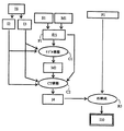
以下の例及び実施例は、図1乃至図6を参照して説明される。図1乃至図3は、本発明による方法の多数の変形例の段階を示す。矩形のボックスは、結果、データ、画像等を表わす。方法の段階は、楕円内に示される。 The following examples and examples are described with reference to FIGS. 1 to 3 show the stages of a number of variants of the method according to the invention. Rectangular boxes represent results, data, images, etc. The method steps are shown in the ellipse.
図1は、方法の第1の変形例のステップ及び結果を図式的に示す。方法は、2つの異なる撮像法により、即ち本例ではPET及びCTに基づく方法により、動く対象の画像を捕捉することを目的とする。異なった撮像法は、動く対象に関して異なった情報が捕捉されることを可能とする。かかる異なった情報はユーザに対して共通に提示されるべきである。 FIG. 1 schematically shows the steps and results of a first variant of the method. The method aims at capturing images of moving objects by two different imaging methods, in this example by methods based on PET and CT. Different imaging methods allow different information about the moving object to be captured. Such different information should be commonly presented to the user.
例えばPET(ポジトロン・エミッション断層撮影法)法により横隔膜の領域において患者の胸部から形成される投影P1が利用可能である(方法自体は図1には示されていない)。PET法は、核医学の分野で知られており、スライス画像又は体積画像の形成を意図したものである。所定の不安定な核種でマークされた代謝製剤が患者に注入され、製剤は組織特異的(tissue-specific)に又は機能特異的(function-specific)に取り込まれる。放射線核種は、崩壊を用いて、崩壊の場所の近傍で異なった連続する処理で2つのγ量子を生じさせ、この量子は正反対の方向に飛び出し、患者を離れ、患者の周りのリング形状の検出器中に配置された適当なセンサによって検出されうる。γ量子は、それらの発生場所から患者を出る点へ進行するとき患者の更なる組織を横切り、組織は、組織の種類に従ってγ量子を多少吸収しうる。概して、γ量子は組織特異的に減衰される。検出されたγ量子全体は、対象の一組の投影P1を形成し、これらの投影P1から、続く再構成中に公知の方法でスライス画像又は体積画像が再構成されうる。PET法は、対象の機能画像を生じさせる。 For example, a projection P1 formed from the patient's chest in the region of the diaphragm by PET (Positron Emission Tomography) method is available (the method itself is not shown in FIG. 1). The PET method is known in the field of nuclear medicine and is intended for the formation of slice images or volume images. A metabolic product marked with a predetermined unstable nuclide is injected into the patient and the product is taken up tissue-specific or function-specific. Radionuclides use decay to produce two gamma quanta in different sequential steps near the location of the decay, which shoots out in the opposite direction, leaves the patient, and detects the ring shape around the patient It can be detected by a suitable sensor placed in the vessel. The gamma quanta traverses the patient's additional tissue as it progresses from their place of origin to the point of exiting the patient, and the tissue may absorb some of the gamma quantum according to the tissue type. In general, gamma quanta are attenuated in a tissue specific manner. The entire detected γ quanta forms a set of projections P1 of interest from which slice images or volume images can be reconstructed in a known manner during subsequent reconstruction. The PET method produces a functional image of the object.
数分間から1時間続く投影P1の捕捉中、患者は、横隔膜が呼吸に従って動く呼吸運動を行う。この呼吸運動は、再構成されたPET画像I0中に動きアーティファクトを生じさせ、このアーティファクトは、対象の不鮮明なぼけた画像として現れる。かかる動きアーティファクトの以下のような少なくとも2つの原因が知られている。
(1)呼吸運動により、組織の所与の場所は検出器に対して相違する位置を占め、従ってこの場所で生ずるγ量子は検出器の異なったセンサによって捕捉される。
(2)略同じ場所で順次に生ずるγ量子は、減衰の原因となる周囲の組織の相対位置が呼吸運動によりX線量子の発生の場所に対して変化するため、異なる程度に減衰される。
During the acquisition of projection P1, which lasts from a few minutes to an hour, the patient performs a breathing movement in which the diaphragm moves according to respiration. This breathing motion causes motion artifacts in the reconstructed PET image I0, which manifests as a blurry blurred image of the subject. At least two causes of such motion artifacts are known:
(1) Due to the respiratory motion, a given location in the tissue occupies a different position relative to the detector, so that the γ quanta generated at this location is captured by different sensors of the detector.
(2) γ quanta generated sequentially at substantially the same location are attenuated to different degrees because the relative position of the surrounding tissue that causes attenuation changes with respect to the location of X-ray quantum generation due to respiratory motion.
図1に図示しないCTに基づく方法によって捕捉された画像I2及びI3もまた利用可能である。CT(コンピュータ断層撮影)法は、例えば、医用分野で公知であり、対象又は患者のスライス画像及び体積画像を形成するのに用いられ、これらの画像は解剖学的構造の情報を含む。CTに基づくシステムについては、以下詳述する。CT画像は、画像捕捉が動きに対してかなり高速に行われうるため、PET画像とは対照的に、かなり少ない動きアーティファクトを含むか又は全く動きアーティファクトを含まない。対象に関する機能情報を伴うPET画像と対象に関する解剖学的構造の情報を伴うCT画像を組み合わせる公知のシステムは、情報の組み合わせのときにPET画像と対象画像の動きアーティファクトを無視し、従って組み合わされた情報は更なるアーティファクト又は誤りを含む。これらのアーティファクト又は誤りは、本発明によりかなり減少される。以下の説明では、上述の(1)の原因によりPET画像中に生ずるアーティファクトが、組み合わされた情報中にどのように考慮に入れられるかについて示す。 Images I2 and I3 captured by a CT-based method not shown in FIG. 1 are also available. CT (computed tomography) methods are known, for example, in the medical field and are used to form slice and volume images of a subject or patient, which images contain anatomical information. The CT based system will be described in detail below. CT images contain much less or no motion artifacts, in contrast to PET images, since image capture can be done much faster with respect to motion. Known systems that combine PET images with functional information about the object and CT images with anatomical structure information about the object ignore the motion artifacts of the PET image and the target image when combining information and are therefore combined The information includes further artifacts or errors. These artifacts or errors are significantly reduced by the present invention. In the following description, it will be shown how artifacts occurring in a PET image due to the cause of (1) above are taken into account in the combined information.
かかる画像の捕捉について示すために、図6中、例として、コンピュータ断層撮影装置及びPETシステムから構成される組合せシステムを示す。コンピュータ断層撮影装置及びPETシステムはいずれも、原理的には、独立のシステムであるが、基準となる共通軸に対して幾何学的に結合されるものとして構成される。画像の捕捉のために、システムは、通常は連続的に用いられ、例えば、2つの目立った動き状態を表わす第1のCT画像が捕捉され、続いてPETデータの捕捉が行われる。 In order to show the capture of such an image, in FIG. 6, as an example, a combined system composed of a computed tomography apparatus and a PET system is shown. Both the computed tomography apparatus and the PET system are in principle independent systems, but are configured to be geometrically coupled to a common common axis. For image capture, the system is typically used continuously, for example, a first CT image representing two prominent motion states is captured, followed by PET data capture.
コンピュータ断層撮影装置は、z方向に対して平行に延びる回転軸14の回りに回転することが可能なガントリ1を含む。このために、ガントリ1は、モータ2により、望ましくは一定の、しかし調整可能な角速度で駆動される。例えばX線管といった放射線源Sは、ガントリ1に取り付けられる。放射線源は、放射線源Sによって生成される放射線から円錐放射線ビーム4を形成するコリメータ装置3を具備する。放射線ビーム4は、円筒状の検査ゾーン13内に存在する動く対象(図示せず)を貫通する。検査ゾーン13を横切った後、X線ビーム4はガントリ1に取り付けられた2次元検出器ユニット16に入射する。
The computed tomography apparatus includes a
放射線ビーム4の開口角αmax(開口角は、x−y平面上のエッジに位置するビーム4の光線が放射線源Sと回転軸14によって画成される平面に対して成す角度として定義される)は、測定値の捕捉中は検査されるべき対象がその中に存在せねばならない検査ゾーン13の直径を決定する。対象の体積画像を発生するために、例えば検査ゾーン13中の台の上に配置された対象は、モータ5により回転軸14又はz軸の方向に対して平行に変位されうる。検出器ユニット16によって捕捉された測定データは、再構成ユニット10へ与えられ、再構成ユニット10は、検査ゾーン13のうちの放射線ビーム14が網羅する部分における吸収分布を測定データから再構成する。2つのモータ2及び5、再構成ユニット10、放射線源S、検出器ユニット16から再構成ユニット10への測定データの転送は、適切な制御ユニット7によって制御される。
The aperture angle α max of the radiation beam 4 (the aperture angle is defined as the angle formed by the ray of the beam 4 located at the edge on the xy plane with respect to the plane defined by the radiation source S and the
モータ2及び5は、放射線源Sと検査ゾーン13が互いに対して螺旋状の経路、即ちいわゆる軌跡に沿って動くよう、ガントリ1の角速度に対する検査ゾーン13の伝搬速度の比が一定であるよう制御されうる。この場合、放射線源Sと検出器ユニット16、又は検査ゾーン16からなる走査ユニットが回転運動を行うか伝搬運動を行うかは重要ではなく、なぜならば相対的な運動のみが重要だからである。対象は、スライス画像の形成のためには変位されない。
The motors 2 and 5 are controlled so that the ratio of the propagation velocity of the
動き信号は、捕捉ユニット12と、対象の動きを検出するよう対象上に配置された動きセンサ15とによって導出される。この信号は、所望であれば、再構成に適した測定データの選択を容易とするよう再構成ユニット10に印加されうる。更に、動き信号(以下詳述)は、本発明によれば動きモデルの決定のために本発明に従って用いられる。
The motion signal is derived by a
更に、PET捕捉ユニット20は、回転軸14に対して同心であるよう配置され、このユニットは、検査ゾーン13中に存在する対象の回りのリングとして配置される。捕捉ユニット20は、対象によって放出されるγ量子を検出する個々のセンサ21を有する。スライス画像を形成するためには、センサ21を互いに隣接してリング状の形態に配置することにより、PET捕捉ユニットを疑似2次元になるよう構成することで十分である。体積画像を生成するために、PET捕捉ユニットは、互いに対して平行に、また、回転軸13回りにあるように配置された複数のかかるセンサのリングを有する。センサ21によって検出される信号は、評価ユニット22に印加され、評価ユニット22は、公知のアルゴリズムにより信号から1つ又はそれ以上のPET画像を形成する。
Furthermore, the
上述の機能に加え、制御ユニット7はまた、CTシステムの取得位置とPETシステムの取得位置の間で対象を変位させるよう配置される。CTデータ捕捉が成功した後、台の上の対象は、制御ユニット7及びモータ5により、関連のある製剤が対象に注入されPETデータが捕捉されるPET捕捉ユニット20の捕捉位置へ変位される。
In addition to the functions described above, the control unit 7 is also arranged to displace the object between the acquisition position of the CT system and the acquisition position of the PET system. After successful CT data acquisition, the object on the platform is displaced by the control unit 7 and motor 5 to the acquisition position of the
データ処理ユニット23は、本発明による方法及び動き信号を用いて、CT画像とPET画像の情報内容を、存在する場合は動きアーティファクトを減少させ、それに従って結果を表示装置11によって視覚化するよう組み合わせる。データ処理ユニットがプログラマブルであるよう構成されていれば、コンピュータプログラムにより本発明による方法を実行することが可能とされる。コンピュータプログラムは、例えばROM又はEPROMといった内部メモリに格納されてもよく、又は、コンピュータプログラムが与えられたディスク又はCD−ROMといったコンピュータプログラムプロダクト中に格納されうる。
The
図示のコンピュータ断層撮影装置及びPET捕捉ユニットは、スライス及び体積画像が捕捉されるよう構成されうる。 The illustrated computed tomography apparatus and PET capture unit can be configured to capture slices and volume images.
図1の画像I2及びI3は、投影P1の捕捉中に対象によって行われる動きの2つの相違する動き状態を表わす。CTに基づく捕捉の方法では本質的に、PETに基づく捕捉に必要とされる時間よりもかなり少ない時間がかかるため、患者の呼吸運動の瞬間的な画像が形成されえ、特に吸入した状態の画像I2及び吐出した状態の画像I3が形成されうる。患者の動きの吸入した及び吐出した状態は、呼吸運動の特に特徴的な状態を表わす。或いは、呼吸運動のCT画像ISのシーケンスは、対象が投影P1の捕捉中と同じ運動を行なっているときに捕捉されうる。続いて、公知の方法を用いて、シーケンスISから2つの画像I2及びI3が抽出される。これは、動きが、投影P1の捕捉中に対象によって行われる動きに対してより正確に対応するという利点を与える。画像I2及びI3が直接捕捉されるとき、患者の中でしばしば不自然な又はわかりにくい動き状態が生じ、このような状態は、自然の呼吸運動中に生ずるものと同じではない。 Images I2 and I3 in FIG. 1 represent two different motion states of the motion performed by the object during capture of projection P1. Because CT-based acquisition methods inherently take much less time than that required for PET-based acquisition, instantaneous images of the patient's respiratory motion can be formed, particularly inhaled images I2 and the discharged image I3 can be formed. The inhaled and exhaled states of patient movement represent a particularly characteristic state of respiratory motion. Alternatively, a sequence of respiratory motion CT images IS may be captured when the subject is performing the same motion as during the capture of projection P1. Subsequently, two images I2 and I3 are extracted from the sequence IS using a known method. This gives the advantage that the movement corresponds more accurately to the movement made by the object during the capture of the projection P1. When images I2 and I3 are captured directly, unnatural or obscure movement conditions often occur in the patient, and such conditions are not the same as those that occur during natural breathing movements.
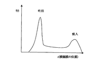
ステップC1において、動き状態関数F1と組み合わせて、動き画像I2及びI3のこれらの状態から対象動きモデルM2が形成される。この種類の動き状態関数F1は、図4中、例として人間の呼吸運動についての頻度関数f(r)として示されている。頻度関数f(r)のy軸は、対象が動きを行っている間に対象が関連のある動き状態をどのくらい頻繁にとるかを示す。x軸は、動きが行われているときにとられる連続的な動き状態rを表わす。換言すれば、頻度関数は、対象が運動を行っている間、他の動き状態に対して所与の動き状態に平均してどれだけ長く留まるかを表わす。表わされたものが正規化されると、この曲線全体に亘る積分は、正確に1となる。呼吸運動中、呼吸運動に関与した器官又は組織が特に頻繁に又は長く吐出された状態(吐出)のままでいるということは、特に重要な面である。方法の更なるステップにおいて頻度のみが関心となる場合、対象が運動を行っている間にとられる動き状態の順序は無視でき、x軸上にプロットされる動き状態は、動きを行っている間は必ずしも互いに連続するものである必要はない。 In step C1, the target motion model M2 is formed from these states of the motion images I2 and I3 in combination with the motion state function F1. This type of motion state function F1 is shown in FIG. 4 as an example of a frequency function f (r) for human respiratory motion. The y-axis of the frequency function f (r) shows how often the subject takes a relevant motion state while the subject is moving. The x-axis represents a continuous motion state r taken when a motion is taking place. In other words, the frequency function represents how long on average a given motion state stays with respect to other motion states while the subject is exercising. When the representation is normalized, the integral over this entire curve is exactly 1. It is a particularly important aspect that during the respiratory movement, the organs or tissues involved in the respiratory movement remain in a state of frequent or long discharge (discharge). If only the frequency is of concern in a further step of the method, the order of motion states taken while the subject is exercising can be ignored and the motion states plotted on the x-axis can be Need not be continuous with each other.
或いは、とられる動き状態の頻度に関する情報を提供するだけでなく、全体の動きの過程(動き状態、並びに、それらの頻度及び時間上の完了)を示す動き状態関数F1を用いることが可能である。しかしながら、かかる動き状態関数は、この変形例の次のステップにおいて使用するには冗長であるため、上述のように頻度関数を用いることで十分である。 Alternatively, it is possible not only to provide information about the frequency of motion states taken, but also to use a motion state function F1 that indicates the overall motion process (motion states and their frequency and completion in time). . However, such a motion state function is redundant to use in the next step of this variation, so it is sufficient to use the frequency function as described above.
公知の動き過程については、動き状態関数F1は、実際の動きを考慮に入れることなく関数モデルM1から導出されうる。これは、特に、殆どの対象において動き過程が非常に似ているか同じであるときに可能である。例えば、人間の呼吸運動の場合に、モデルM1が図1の頻度関数f(r)によって形成されると、これは動き状態関数F1として直接考えることができ、動きモデルM2を決定するのに使用されうる。或いは、実際の動き過程は、適当なセンサS1によって決定されうる。呼吸運動の場合、例えば、呼吸運動は患者に取り付けられた呼吸運動センサによるPET投影P1の捕捉中に決定され、そこから、頻度関数f(r)、又はより一般的には動き状態関数F1が動きモデルM2の構築のために導出される。 For known motion processes, the motion state function F1 can be derived from the function model M1 without taking into account the actual motion. This is particularly possible when the movement process is very similar or the same for most objects. For example, in the case of human respiratory motion, if model M1 is formed by frequency function f (r) of FIG. 1, this can be considered directly as motion state function F1 and is used to determine motion model M2. Can be done. Alternatively, the actual movement process can be determined by a suitable sensor S1. In the case of respiratory motion, for example, the respiratory motion is determined during acquisition of the PET projection P1 by a respiratory motion sensor attached to the patient, from which the frequency function f (r), or more generally the motion state function F1, is obtained. Derived for the construction of the motion model M2.
ステップC1では、動きモデルM2は、画像I2及びI3と、動き状態関数F1とから導出される。各画像I2及びI3は、対象の夫々の既知の動き状態を表わし、各動き状態もまた動き状態関数F1中に表わされる。動き過程中に対象の全ての構成要素が局所的に線形に動くとすると、即ち、異なった方向及び長さの直線的な経路に沿って動くとすると、画像I2とI3中に示す動き状態の間では、画像I2又はI3の一方に表わされる各画素について、又は、各対象構成要素について、動きの実行は動き状態関数F1によって決定されうる。この位置特異的な動き過程は、動きベクトル場中に維持されえ、動き状態関数F1と共に動きモデルM2を構成する。動きベクトルは、このように、2つの動き状態の間毎に動きを行う間、画素又は対象構成要素が動く方向又は動く速度又は動く距離を示す。 In step C1, the motion model M2 is derived from the images I2 and I3 and the motion state function F1. Each image I2 and I3 represents a respective known motion state of the object, and each motion state is also represented in the motion state function F1. If all the components of interest move locally and linearly during the movement process, i.e. move along a linear path of different direction and length, the movement states shown in images I2 and I3 In between, for each pixel represented in one of the images I2 or I3, or for each target component, the performance of the motion can be determined by the motion state function F1. This position-specific motion process can be maintained in the motion vector field and constitutes the motion model M2 with the motion state function F1. The motion vector thus indicates the direction or speed or distance of movement of the pixel or target component while performing motion between each of the two motion states.
数学的に言えば、この種類のベクトル場は、 Mathematically speaking, this kind of vector field is
![]()
〔外1〕
![]()
〔外2〕
![]()
〔外3〕

![]()
[Outside 1]
![]()
[Outside 2]
![]()
[Outside 3]
![]()
画像I3中に表わす動き状態を表わし、
![]()
Representing the motion state represented in image I3;
![]()
![]()
![]()
〔外4〕
![]()
〔外5〕
![]()
![]()
[Outside 4]
![]()
[Outside 5]
![]()
次のステップC2は、画像I2及びI3から、画像I0と略同じ動きアーティファクトを示す画像I4を形成することを目的とする。これは、画像I2又はI3の一方から開始して、残る動き状態の最初の人為的な画像が、動きモデルM2によって形成され、画像I4を形成するよう人為的な画像が重ね合わされることで達成され、 The next step C2 aims to form an image I4 that shows substantially the same motion artifact as the image I0 from the images I2 and I3. This is achieved by starting with one of the images I2 or I3, the first artificial image of the remaining motion state is formed by the motion model M2, and the artificial image is superimposed to form the image I4. And
〔外6〕
![]()
〔外7〕
![]()
![]()
[Outside 7]
![]()
同様に、PET画像I0の形成の理論的な考察によれば、PET画像I0もまた当該の滞留持続時間によって重み付けされた全ての動き状態の重畳を構成するという結果が得られる。このことはこれが初期の動き状態の画像I0a(本例では図示せず)、頻度関数f(r)、及び
〔外8〕
![]()
![]()
理想的な場合、画像10aは、画像I3と同じ動き状態を表わし、
〔外9〕
![]()
[Outside 9]
![]()
図6に示すような組合せ装置の代わりとして、画像I0並びに画像I2及びI3は、2つの独立のシステムによって捕捉されうる。対象は、例えばPETシステムといった第1の装置内に配置され、PET画像が捕捉される。続いて、対象は、第2のシステム内に配置され、CT画像が捕捉される。2つのシステムの場所的な隔たりにより、PET画像10中の対象構成要素は、通常はCT画像I2、I3、及びI4中のものとは異なって局所化されるため、画像I4及びI0の不適切な直接的な重畳又は直接的な比較のみが行われうる。従って、ステップR2では、いわゆる位置合わせ操作が行われる。ステップR2は任意であり、画像I0の座標系が(図6に示すシステムの場合のように)画像I2及びI3の座標系に適切に正確に対応するときは必要でない。I0は、I5と等しくされえ、方法は以下に説明するように続けられる。
As an alternative to the combination device as shown in FIG. 6, image I0 and images I2 and I3 can be captured by two independent systems. The object is placed in a first device, for example a PET system, and a PET image is captured. Subsequently, the object is placed in the second system and a CT image is captured. Due to the spatial separation of the two systems, the target component in the
位置合わせは、対応する構造を有する2つ又はそれ以上の画像間で座標系を等しくする一般的に知られた方法である。異なった内容の2つの同一の対象の物理的な対応性もまた生じうる。これは、例えば、同じ対象の機能的なPET画像及び解剖学的なCT画像の場合である。位置合わせがうまくいった後、1つの画像中に表わされる対象部分は、決定された座標変化によって他の画像中の対応する対象部分に関連付けられ得る。結果として、例えば、1つの画像中に示される対象部分は、それらが他の画像中に表わされる同一の対象部分の対応する位置を占めるようシフトされうる。 Registration is a commonly known method of equalizing the coordinate system between two or more images having corresponding structures. A physical correspondence of two identical objects with different contents can also occur. This is the case for example for functional PET images and anatomical CT images of the same object. After successful alignment, the target portion represented in one image can be related to the corresponding target portion in the other image by the determined coordinate change. As a result, for example, the target portions shown in one image can be shifted so that they occupy corresponding positions of the same target portion represented in the other image.
非特許文献1は、このようなCT画像とPET画像の位置合わせがどのように実行されうるかを示す。位置合わせは一般的に知られているため、これについてはここでは更に詳述しない。しかしながら、非特許文献1にも記載されているように、公知のPETシステムでは、位置合わせを容易とするために、実際のPET画像に加えて透過画像が捕捉される。核種でマーク付けされた代謝製剤の注入の前に、このために患者の周りの軌跡に沿って放射能源が配置され、この源は、患者を貫通する患者の方向に光線を発し、光線は放射線源とは反対側に配置されたPET検出器のセンサによって検出される。続いて再構成される透過画像は、原理的にはCT画像と同様であり、その中に含まれる解剖学的な情報により、実際のPET画像の画質が低い場合は特に、CT画像との位置合わせに、よりよく適している。透過画像とCT画像の間の座標変換が決定されると、透過画像の座標系とPET画像の座標系は実質的に同一であるため、実際のPET画像とCT画像の座標は対応するようにされうる。この方法は、図1には図示しないが、それでもやはり本願で使用されうる。
位置合わせR2が成功した後、画像I0の画素又は対象構成要素は、画像I4の座標系中に変換されうる。これは、PET画像15を生成する。可能な代替案、即ち、画像I4を画像I0の座標系へ変換することについては本願では詳述しない。画像I4とI5の比較又は組合せは、いずれの画像も対象の動きの実質的に同じ動きアーティファクトを示し、いずれの画像も同じ座標系に関して対象を表わすため、ここで行われうる。例えば医師である観察者は、所与の適用について偽り(falsification)のない画像I0の表現(この意味での座標変換は偽りを表わさない)を、そこからの情報と他の画像からの情報の比較又は組合せを可能とするよう、望むことがある。従来技術は、単に、2つの画像I2又はI3のうちの一方のみを画像I0と比較又は組み合わせる可能性のみを提供する。画像I0とは対照的に、画像I2又はI3は動きアーティファクトを示さず、従って、一方では適切な座標変換の探索はより困難であり、他方では組合せ又は変換自体は困難を伴ってのみ可能である。
After registration R2 is successful, the pixel or target component of image I0 can be transformed into the coordinate system of image I4. This generates a
図1中にステップR3として示すかかる比較又は組合せは、原理的に知られており、例えば、重畳によって、又は、隣接に配置された画像によって、又は、手で選択された境界を伴った部分的な重畳によって、又は、手で選択可能な境界を伴う他の画像中の1つの画像の部分的な画像化によって実現されうる。ステップR3の結果は、画像I6を構成する。 Such a comparison or combination shown in FIG. 1 as step R3 is known in principle, for example by superposition, by adjacently arranged images, or with a hand-selected boundary. It can be realized by superposition or by partial imaging of one image in another image with hand selectable borders. The result of step R3 constitutes image I6.
当該の用途に依存して、システムのユーザが画像I6を所与の情報へ制限すること、又は特に所与の画像をハイライトすることが有用であり得る。このために、アーティファクトを含み、動きの1つの動き状態のみが表わされている画像I6をフォーカシングするよう任意のステップB1が行われうる。線形の動きに適したフォーカシングのための公知のアルゴリズムは、A.K. Katsaggelos, "Iterative image restoration algorithm", OPTICAL ENGINEERING, 1989年7月、第28巻、第7号、第735頁以降に記載されている。特に、式(1)は、動きの不鮮明さが一般的にはどのようにして、動きを線形の動きへモデル化することにより表現されえ、方法の更なる過程において補償されうるかを示す。 Depending on the application in question, it may be useful for the user of the system to restrict the image I6 to given information, or in particular to highlight a given image. To this end, an optional step B1 can be performed to focus on an image I6 that contains artifacts and represents only one motion state of motion. Known algorithms for focusing suitable for linear motion are described in AK Katsaggelos, "Iterative image restoration algorithm", OPTICAL ENGINEERING, July 1989, Vol. 28, No. 7, p. . In particular, equation (1) shows how motion blur can generally be expressed by modeling the motion into a linear motion and can be compensated for in further steps of the method.
図2は、組合せシステムにおける本発明による方法の更なる変形例を示す図である。図1に示すように、再び動きモデルM2が決定され、またPET画像I0が形成される。図1に示される位置合わせR2は、画像I0,I2及びI3の座標系の対応性が適切であるため、省かれる。 FIG. 2 shows a further variant of the method according to the invention in a combination system. As shown in FIG. 1, the motion model M2 is determined again, and a PET image I0 is formed. The alignment R2 shown in FIG. 1 is omitted because the correspondence of the coordinate systems of the images I0, I2 and I3 is appropriate.
ステップB2において、図1のステップB1と同様に、画像I0のフォーカシングが行われる。図1に示すフォーカシングとは対照的に、図2に示すフォーカシングB2は、より鮮明なPET画像I8が捕捉されたCT画像、本例では画像I2、と同じ動き状態を表わすよう、行われる。結果として、画像I8は、本例ではI2である元のCT画像と直接的に比較又は組み合わされうる。或いは、この処理は、画像I3によって又は画像シーケンスISからの画像によって行われうる。比較ステップR4では、図1のステップR3に示すのと同じ方法が示される。画像I9は、結果として得られる画像である。 In step B2, focusing of the image I0 is performed as in step B1 of FIG. In contrast to the focusing shown in FIG. 1, the focusing B2 shown in FIG. 2 is performed to represent the same motion state as the CT image in which a sharper PET image I8 is captured, in this example, the image I2. As a result, the image I8 can be directly compared or combined with the original CT image, which in this example is I2. Alternatively, this processing can be performed by the image I3 or by an image from the image sequence IS. In the comparison step R4, the same method as shown in step R3 of FIG. 1 is shown. Image I9 is the resulting image.
図2の方法(図示せず)の代わりに、画像I0と画像I2及びI3の座標系が異なる場合、図1の組合せ画像16の代わりに画像I5に対してフォーカシングが適用される。以前に実行された位置合わせR2の結果として、画像15の座標系が画像I4の座標系に対応し、従って動きモデルM2の座標系に対応することが達成される。このことは、動きモデルM2による画像I5のフォーカシングB1を可能とする。結果として得られる画像は、動きの動き状態を表わし実質的には全く動きアーティファクトを含まないPET画像である。
Instead of the method of FIG. 2 (not shown), if the image I0 and the images I2 and I3 have different coordinate systems, focusing is applied to the image I5 instead of the combined
図3は、動きモデルによる画像の情報内容を向上させる更なる可能性を示す図である。公知のPETシステムでは、透過画像は、上述の方法によって、即ち実際のPET画像に加えて捕捉される。この透過画像は、放射性の放射線の位置特異的な(location−specific)減衰を表わす。この減衰情報は、周囲の組織によるγ量子の吸収を補正するために(減衰補正)、投影P1の再構成R1のために用いられる。I.T.Hsiao外による「Noise Propagation from Attenuation Correction into PET Reconstructions」、(「Nuclear Science&Medical Imaging including Nuclear Power Systems, 2000 Symposium、IEEE ISBN 0−7803−6503−8」には、様々な方法が開示されており、例えば表1には、位置特異的な減衰の補正について記載されている。式(4)は、分布効果を考慮に入れつつ位置特異的な減衰により、線形の再構成オペレータとして表現される再構成を増やす可能性を示している。 FIG. 3 is a diagram illustrating a further possibility of improving the information content of an image by a motion model. In known PET systems, the transmission image is captured by the method described above, ie in addition to the actual PET image. This transmission image represents the location-specific attenuation of the radioactive radiation. This attenuation information is used for reconstruction R1 of the projection P1 in order to correct the absorption of γ quanta by the surrounding tissue (attenuation correction). Various methods are disclosed in “Noise Propagation from Attenuation Correction into PET Reconstructions” by ITHsiao (“Nuclear Science & Medical Imaging including Nuclear Power Systems, 2000 Symposium, IEEE ISBN 0-7803-6503-8” For example, correction for position-specific attenuation is described in Table 1. Equation (4) is a reconstruction represented as a linear reconstruction operator with position-specific attenuation taking into account the distribution effect. Shows the possibility of increasing.
しかしながら、透過画像は、実際のPET画像とは対照的に捕捉時間が動きの持続時間と比較して短いため、これらの方法は、僅かな動きアーティファクトのみを含むか又は全く動きアーティファクトを含まないという欠点がある。結果として、減衰情報は適切には使用されず、上述の原因2によるPET画像中の動きアーティファクトは考慮に入れられない。 However, because transmission images are short in acquisition time compared to the duration of motion as opposed to actual PET images, these methods contain only a few motion artifacts or no motion artifacts at all. There are drawbacks. As a result, the attenuation information is not used properly and does not take into account motion artifacts in the PET image due to cause 2 above.
従って、本発明によれば、PET画像I10の再構成R5は、図1に示すように、CT画像I2及びI3から、並びに、動きモデルM2から形成される透過画像I4を用いる。画像I4は、本質的には、いかなる減衰情報もなしに再構成されたPET画像と同じ動きアーティファクトを含む。結果として、PET画像中の動きアーティファクトは考慮に入れられ、画像I4からの減衰情報を用いる再構成R5は、従来の透過画像を用いた再構成よりも定量的に向上された画像I10を生成する。 Therefore, according to the present invention, the reconstruction R5 of the PET image I10 uses the transmission image I4 formed from the CT images I2 and I3 and the motion model M2, as shown in FIG. Image I4 contains essentially the same motion artifacts as the reconstructed PET image without any attenuation information. As a result, motion artifacts in the PET image are taken into account, and reconstruction R5 using attenuation information from image I4 produces an image I10 that is quantitatively improved over reconstruction using conventional transmission images. .
概して、図1、図2、及び図3の方法は、方法の様々な結果を観察者に提示することを可能とするよう、システム内で同時に使用されうる。図3の方法は、図1及び図2の方法と任意に組み合わされえ、即ち、使用されるシステムが組合せシステムであるかぎり組み合わされえ、何故ならばPETシステムの座標系は、組合せシステムの場合以外はCTシステムの座標系に略対応するためである。 In general, the methods of FIGS. 1, 2, and 3 can be used simultaneously in the system to allow various results of the method to be presented to an observer. The method of FIG. 3 can be arbitrarily combined with the methods of FIGS. 1 and 2, ie, as long as the system used is a combination system, because the coordinate system of the PET system is the case of the combination system. The reason is that it substantially corresponds to the coordinate system of the CT system.
また、図1、図2及び図3に示す方法は、CT及びPETに限られるものではないことに留意すべきである。例えば、PETに基づく方法の代わりに磁気共鳴撮像法によって画像I0を捕捉すること、又は、CTに基づく方法を用いる代わりに、超音波又は高速磁気共鳴断層撮影法によって画像I2及びI3を捕捉することが可能である。本発明による方法は、一般的には、画像中に存在する動きアーティファクトを考慮に入れつつ動く対象についての異なった情報を含む画像を比較する可能性を与え、医用以外の用途もまた可能である。例えば、動きアーティファクトを含む走っている車の画像は、感熱カメラによって捕捉されえ、更なる画像は従来の写真方法によって捕捉されうる。感熱カメラの画像は、位置特異的な機能的な処理を示すのに対して、写真画像は対象の構造上の特徴を表わす。有利に動きアーティファクトを考慮に入れつつ組合せ画像を形成するようかかる異なる種類の情報を重畳することは、全ての情報を同時に観察者に提示することを可能とする。 It should also be noted that the methods shown in FIGS. 1, 2 and 3 are not limited to CT and PET. For example, capturing images I0 by magnetic resonance imaging instead of PET based methods, or capturing images I2 and I3 by ultrasound or fast magnetic resonance tomography instead of using CT based methods Is possible. The method according to the invention generally gives the possibility to compare images containing different information about moving objects taking into account the motion artifacts present in the image, and non-medical applications are also possible . For example, an image of a running car containing motion artifacts can be captured by a thermal camera, and further images can be captured by conventional photographic methods. A thermal camera image shows a position-specific functional process, whereas a photographic image represents a structural feature of the object. Superimposing such different types of information to form a combined image, advantageously taking into account motion artifacts, makes it possible to present all information to the observer at the same time.
Claims (12)
(a)出来る限り少ない動きアーティファクトを伴って夫々の動き状態での対象を表わす2つの更なる画像を用いる段階と、
(b)前記2つの動き状態間で前記動きを行っている間に前記対象によってとられる動き状態を特徴付ける動きモデルを決定する段階と、
(c)前記動きモデル及び前記2つの更なる画像から、前記対象が前記動きを行なったかのように少なくともおおよそ前記対象を表わす中間画像を形成する段階と、
(d)前記中間画像及び前記第1の画像から組合せ画像を形成する段階とを含む、方法。 A method for improving image content that can be derived from a first image containing motion artifacts of a moving object comprising:
(A) using two additional images representing the object in each motion state with as few motion artifacts as possible;
(B) determining a motion model characterizing a motion state taken by the object while performing the motion between the two motion states;
(C) forming, from the motion model and the two further images, an intermediate image representing at least approximately the object as if the object had performed the motion;
(D) forming a combined image from the intermediate image and the first image.
(a)出来る限り少ない動きアーティファクトを伴って夫々の動き状態での対象を表わす2つの更なる画像を用いる段階と、
(b)前記2つの動き状態間で前記動きを行っている間に前記対象によってとられる動き状態を特徴付ける動きモデルを決定する段階と、
(c)前記第1の画像を前記動きモデルによってフォーカシングする段階とを含む、方法。 A method for improving image content that can be derived from a first image containing motion artifacts of a moving object comprising:
(A) using two additional images representing the object in each motion state with as few motion artifacts as possible;
(B) determining a motion model characterizing a motion state taken by the object while performing the motion between the two motion states;
(C) focusing the first image with the motion model.
(a)出来る限り少ない動きアーティファクトを伴って夫々の動き状態での対象を表わす2つの更なる画像を用いる段階と、
(b)前記2つの動き状態間で前記動きを行っている間に前記対象によってとられる動き状態を特徴付ける動きモデルを決定する段階と、
(c)前記動きモデル及び前記2つの更なる画像から、前記対象が前記動きを行なったかのように少なくともおおよそ前記対象を表わす中間画像を形成する段階と、
(d)前記対象の投影及び前記中間画像から前記第1の画像を再構成する段階とを含む、方法。 A method for improving the image content that can be derived from a first image of a moving object that is to be reconstructed from a projection and that includes a motion artifact,
(A) using two additional images representing the object in each motion state with as few motion artifacts as possible;
(B) determining a motion model characterizing a motion state taken by the object while performing the motion between the two motion states;
(C) forming from the motion model and the two additional images an intermediate image representing at least approximately the object as if the object had performed the motion;
(D) reconstructing the first image from the projection of the object and the intermediate image.
第2の撮像方法により画像及び/又は投影を形成する装置と、
請求項1乃至3のうちいずれか一項記載の方法又はこれらの方法の組合せを実行するデータ処理ユニットを含む画像処理システムとを含む、
特に医用検査装置である検査装置。 An apparatus for forming an image and / or projection by a first imaging method;
An apparatus for forming an image and / or projection by a second imaging method;
An image processing system comprising a data processing unit for performing the method according to claim 1 or a combination of these methods.
An inspection device that is in particular a medical inspection device.
Applications Claiming Priority (2)
| Application Number | Priority Date | Filing Date | Title |
|---|---|---|---|
| DE2002131061 DE10231061A1 (en) | 2002-07-10 | 2002-07-10 | Process and system for improving the information content in an image |
| PCT/IB2003/003011 WO2004008390A2 (en) | 2002-07-10 | 2003-07-08 | Motion artifact correction of tomographical images |
Publications (2)
| Publication Number | Publication Date |
|---|---|
| JP2005532137A true JP2005532137A (en) | 2005-10-27 |
| JP2005532137A5 JP2005532137A5 (en) | 2006-08-24 |
Family
ID=29761820
Family Applications (1)
| Application Number | Title | Priority Date | Filing Date |
|---|---|---|---|
| JP2004520990A Withdrawn JP2005532137A (en) | 2002-07-10 | 2003-07-08 | Method and system for improving information content of image |
Country Status (6)
| Country | Link |
|---|---|
| US (1) | US7558439B2 (en) |
| EP (1) | EP1522045B1 (en) |
| JP (1) | JP2005532137A (en) |
| AU (1) | AU2003244998A1 (en) |
| DE (1) | DE10231061A1 (en) |
| WO (1) | WO2004008390A2 (en) |
Cited By (3)
| Publication number | Priority date | Publication date | Assignee | Title |
|---|---|---|---|---|
| WO2009091200A2 (en) * | 2008-01-15 | 2009-07-23 | E-Woo Technology Co.,Ltd | Method for eliminating metal artifacts in x-ray ct images |
| JP2011503569A (en) * | 2007-11-09 | 2011-01-27 | コーニンクレッカ フィリップス エレクトロニクス エヌ ヴィ | MR-PET periodic motion gating and correction |
| WO2013094186A1 (en) * | 2011-12-18 | 2013-06-27 | 国立大学法人京都大学 | Motion-tracking x-ray ct image processing method and motion-tracking x-ray ct image processing device |
Families Citing this family (31)
| Publication number | Priority date | Publication date | Assignee | Title |
|---|---|---|---|---|
| GB0318701D0 (en) * | 2003-08-08 | 2003-09-10 | Inst Of Cancer Res The | A method and apparatus for image processing |
| DE602004015503D1 (en) * | 2003-12-08 | 2008-09-11 | Philips Intellectual Property | Computer tomography method for periodically moving objects |
| DE102004050172B4 (en) * | 2004-08-20 | 2010-09-02 | "Stiftung Caesar" (Center Of Advanced European Studies And Research) | 3D reconstruction with oblique geometry |
| JP2008523871A (en) * | 2004-12-15 | 2008-07-10 | コーニンクレッカ フィリップス エレクトロニクス エヌ ヴィ | Multimodality image registration |
| DE102005017492B4 (en) * | 2005-04-15 | 2007-04-19 | Siemens Ag | Method for computationally compensating a periodic movement of an organ and image recording system |
| DE102005023907A1 (en) | 2005-05-24 | 2006-12-07 | Siemens Ag | Method for determining positron emission measurement information in the context of positron emission tomography |
| WO2007015199A2 (en) * | 2005-08-04 | 2007-02-08 | Koninklijke Philips Electronics, N.V. | Motion compensation in functional imaging |
| WO2008026141A2 (en) * | 2006-08-29 | 2008-03-06 | Koninklijke Philips Electronics N.V. | Reduction of heart motion artifacts in thoracic ct imaging |
| US8548568B2 (en) * | 2006-09-08 | 2013-10-01 | General Electric Company | Methods and apparatus for motion compensation |
| DE102007034956A1 (en) * | 2007-07-26 | 2009-02-05 | Siemens Ag | Method for detecting a neuropathologically altered brain region |
| DE102007034953B4 (en) | 2007-07-26 | 2016-09-22 | Siemens Healthcare Gmbh | A method for recording movements of a patient and associated medical device |
| US8610965B2 (en) * | 2007-11-26 | 2013-12-17 | Optelec Development B.V. | Reproduction device, assembly of a reproductive device and an indication body, and a method for reproducing an image portion |
| US8406495B2 (en) * | 2008-09-17 | 2013-03-26 | Koninklijke Philips Electronics N.V. | MR segmentation using transmission data in hybrid nuclear/MR imaging |
| US8600136B2 (en) * | 2008-09-19 | 2013-12-03 | Koninklijke Philips N.V. | Method for generation of attenuation map in PET-MR |
| JP5815573B2 (en) | 2010-03-18 | 2015-11-17 | コーニンクレッカ フィリップス エヌ ヴェKoninklijke Philips N.V. | Functional image data enhancement method and enhancer |
| US9330493B2 (en) | 2010-12-15 | 2016-05-03 | Fpinnovations | Method for generating a 3D representation of an object |
| EP2578148A1 (en) * | 2011-10-04 | 2013-04-10 | Koninklijke Philips Electronics N.V. | Medical imaging system with motion detection |
| DE102012216759A1 (en) | 2012-09-19 | 2014-03-20 | Siemens Aktiengesellschaft | A method for generating a PET image data set of a moving examination subject and device therefor |
| JP2014147689A (en) * | 2013-01-08 | 2014-08-21 | Toshiba Corp | Medical image diagnostic apparatus, nuclear medicine diagnostic system, x-ray ct apparatus and bed device |
| CN104955396B (en) * | 2013-02-21 | 2017-11-03 | 株式会社日立制作所 | X ray CT device and image reconstructing method |
| CN103544681B (en) * | 2013-08-27 | 2017-06-06 | 清华大学 | The restoration methods of non-homogeneous motion blur image |
| WO2016110420A1 (en) * | 2015-01-05 | 2016-07-14 | Koninklijke Philips N.V. | Digital subtraction angiography |
| DE102015204718A1 (en) | 2015-03-16 | 2016-09-22 | Siemens Healthcare Gmbh | Compensation of image artifacts in a medical imaging |
| US9905044B1 (en) | 2016-08-25 | 2018-02-27 | General Electric Company | Systems and methods for functional imaging |
| US10993689B2 (en) * | 2017-08-31 | 2021-05-04 | General Electric Company | Method and system for motion assessment and correction in digital breast tomosynthesis |
| US10803633B2 (en) | 2018-02-06 | 2020-10-13 | General Electric Company | Systems and methods for follow-up functional imaging |
| US10740983B2 (en) * | 2018-06-01 | 2020-08-11 | Ebay Korea Co. Ltd. | Colored three-dimensional digital model generation |
| EP3896641A1 (en) * | 2020-04-16 | 2021-10-20 | Siemens Healthcare GmbH | Correcting object movement during mr imaging |
| US11309072B2 (en) | 2020-04-21 | 2022-04-19 | GE Precision Healthcare LLC | Systems and methods for functional imaging |
| US11300695B2 (en) | 2020-04-24 | 2022-04-12 | Ronald Nutt | Time-resolved positron emission tomography encoder system for producing event-by-event, real-time, high resolution, three-dimensional positron emission tomographic image without the necessity of performing image reconstruction |
| US11054534B1 (en) | 2020-04-24 | 2021-07-06 | Ronald Nutt | Time-resolved positron emission tomography encoder system for producing real-time, high resolution, three dimensional positron emission tomographic image without the necessity of performing image reconstruction |
Family Cites Families (16)
| Publication number | Priority date | Publication date | Assignee | Title |
|---|---|---|---|---|
| EP0630481B1 (en) * | 1992-03-09 | 1999-06-30 | University Of Washington | Image neurography and diffusion anisotropy imaging |
| US5546472A (en) * | 1992-08-07 | 1996-08-13 | Arch Development Corp. | Feature guided method and apparatus for obtaining an image of an object |
| US5361763A (en) * | 1993-03-02 | 1994-11-08 | Wisconsin Alumni Research Foundation | Method for segmenting features in an image |
| US5839440A (en) * | 1994-06-17 | 1998-11-24 | Siemens Corporate Research, Inc. | Three-dimensional image registration method for spiral CT angiography |
| US5647360A (en) * | 1995-06-30 | 1997-07-15 | Siemens Corporate Research, Inc. | Digital subtraction angiography for 3D diagnostic imaging |
| US5690106A (en) * | 1995-06-30 | 1997-11-25 | Siemens Corporate Research, Inc. | Flexible image registration for rotational angiography |
| US6088611A (en) * | 1995-08-18 | 2000-07-11 | The Board Of Trustees Of The University Of Illinois | Model based method for high resolution dynamic imaging |
| US5768413A (en) * | 1995-10-04 | 1998-06-16 | Arch Development Corp. | Method and apparatus for segmenting images using stochastically deformable contours |
| US5850486A (en) * | 1996-04-29 | 1998-12-15 | The Mclean Hospital Corporation | Registration of image data |
| US6178271B1 (en) * | 1996-04-29 | 2001-01-23 | The Mclean Hospital Corporation | Methods and systems for registering image data |
| GB9614407D0 (en) * | 1996-07-09 | 1996-09-04 | Secr Defence | Method for imaging artefact reduction |
| US7194117B2 (en) * | 1999-06-29 | 2007-03-20 | The Research Foundation Of State University Of New York | System and method for performing a three-dimensional virtual examination of objects, such as internal organs |
| US5910728A (en) * | 1996-11-12 | 1999-06-08 | Beth Israel Deaconess Medical Center | Simultaneous acquisition of spatial harmonics (SMASH): ultra-fast imaging with radiofrequency coil arrays |
| US6075836A (en) * | 1997-07-03 | 2000-06-13 | University Of Rochester | Method of and system for intravenous volume tomographic digital angiography imaging |
| US6229570B1 (en) * | 1998-09-25 | 2001-05-08 | Lucent Technologies Inc. | Motion compensation image interpolation—frame rate conversion for HDTV |
| US6490476B1 (en) * | 1999-10-14 | 2002-12-03 | Cti Pet Systems, Inc. | Combined PET and X-ray CT tomograph and method for using same |
-
2002
- 2002-07-10 DE DE2002131061 patent/DE10231061A1/en not_active Withdrawn
-
2003
- 2003-07-08 WO PCT/IB2003/003011 patent/WO2004008390A2/en active Application Filing
- 2003-07-08 JP JP2004520990A patent/JP2005532137A/en not_active Withdrawn
- 2003-07-08 AU AU2003244998A patent/AU2003244998A1/en not_active Abandoned
- 2003-07-08 EP EP03738465.8A patent/EP1522045B1/en not_active Expired - Lifetime
- 2003-07-08 US US10/520,988 patent/US7558439B2/en not_active Expired - Fee Related
Cited By (6)
| Publication number | Priority date | Publication date | Assignee | Title |
|---|---|---|---|---|
| JP2011503569A (en) * | 2007-11-09 | 2011-01-27 | コーニンクレッカ フィリップス エレクトロニクス エヌ ヴィ | MR-PET periodic motion gating and correction |
| WO2009091200A2 (en) * | 2008-01-15 | 2009-07-23 | E-Woo Technology Co.,Ltd | Method for eliminating metal artifacts in x-ray ct images |
| WO2009091200A3 (en) * | 2008-01-15 | 2009-10-08 | (주)이우테크놀로지 | Method for eliminating metal artifacts in x-ray ct images |
| KR100923098B1 (en) * | 2008-01-15 | 2009-10-22 | (주)이우테크놀로지 | Method for removing metal artifact of X-ray CT image |
| WO2013094186A1 (en) * | 2011-12-18 | 2013-06-27 | 国立大学法人京都大学 | Motion-tracking x-ray ct image processing method and motion-tracking x-ray ct image processing device |
| JPWO2013094186A1 (en) * | 2011-12-18 | 2015-04-27 | 国立大学法人京都大学 | Motion following X-ray CT image processing method and motion following X-ray CT image processing apparatus |
Also Published As
| Publication number | Publication date |
|---|---|
| WO2004008390A2 (en) | 2004-01-22 |
| AU2003244998A1 (en) | 2004-02-02 |
| EP1522045A2 (en) | 2005-04-13 |
| DE10231061A1 (en) | 2004-01-22 |
| US20050226527A1 (en) | 2005-10-13 |
| EP1522045B1 (en) | 2014-11-19 |
| AU2003244998A8 (en) | 2004-02-02 |
| WO2004008390A3 (en) | 2004-07-01 |
| US7558439B2 (en) | 2009-07-07 |
Similar Documents
| Publication | Publication Date | Title |
|---|---|---|
| JP2005532137A (en) | Method and system for improving information content of image | |
| KR101651845B1 (en) | Reconstruction of image data by means of contour data | |
| JP5348855B2 (en) | Object image reconstruction method and apparatus for performing the method | |
| EP2501290B1 (en) | Scan plan field of view adjustor, determiner, and/or quality assessor | |
| KR101728046B1 (en) | Tomography apparatus and method for reconstructing a tomography image thereof | |
| EP2005394B1 (en) | Method for reconstruction images and reconstruction system for reconstructing images | |
| JP5571317B2 (en) | Method for correcting multi-modality imaging data | |
| US8768030B2 (en) | CT measurement with multiple X-ray sources | |
| US20080267455A1 (en) | Method for Movement Compensation of Image Data | |
| US20110044559A1 (en) | Image artifact reduction | |
| US8401144B2 (en) | Method and apparatus for correcting artifacts in circular CT scans | |
| WO2011061644A1 (en) | Motion correction in radiation therapy | |
| JP3987024B2 (en) | Method and system for enhancing tomosynthesis images using lateral filtering | |
| JP2004188163A (en) | Tomography apparatus | |
| JP2011527584A (en) | Device for generating images of moving objects | |
| KR101783964B1 (en) | Tomography apparatus and method for reconstructing a tomography image thereof | |
| JP4752468B2 (en) | Cross-sectional image reconstruction apparatus and X-ray imaging apparatus using the same | |
| KR101698850B1 (en) | Medical imaging device and image compensating method thereof | |
| JP2011502683A (en) | Imaging apparatus, imaging method, and computer program for determining image of region of interest | |
| US11786193B2 (en) | Metal artifacts reduction in cone beam reconstruction | |
| KR20160000271A (en) | Medical imaging device and image compensating method thereof | |
| CN113935936A (en) | Method and device for reconstructing fault fusion image | |
| US20150078646A1 (en) | Method and device for displaying an object with the aid of x-rays | |
| KR20200064287A (en) | Method and apparatus for spiral ct image reconstruction using weight according to angle |
Legal Events
| Date | Code | Title | Description |
|---|---|---|---|
| A521 | Request for written amendment filed |
Free format text: JAPANESE INTERMEDIATE CODE: A523 Effective date: 20060707 |
|
| A621 | Written request for application examination |
Free format text: JAPANESE INTERMEDIATE CODE: A621 Effective date: 20060707 |
|
| A761 | Written withdrawal of application |
Free format text: JAPANESE INTERMEDIATE CODE: A761 Effective date: 20070914 |