JP2005531792A - Polarization recycling (recovery) equipment - Google Patents
Polarization recycling (recovery) equipment Download PDFInfo
- Publication number
- JP2005531792A JP2005531792A JP2003553318A JP2003553318A JP2005531792A JP 2005531792 A JP2005531792 A JP 2005531792A JP 2003553318 A JP2003553318 A JP 2003553318A JP 2003553318 A JP2003553318 A JP 2003553318A JP 2005531792 A JP2005531792 A JP 2005531792A
- Authority
- JP
- Japan
- Prior art keywords
- light
- polarization
- optical path
- recovery system
- reflective polarizer
- Prior art date
- Legal status (The legal status is an assumption and is not a legal conclusion. Google has not performed a legal analysis and makes no representation as to the accuracy of the status listed.)
- Pending
Links
- 230000010287 polarization Effects 0.000 title claims abstract description 84
- 238000011084 recovery Methods 0.000 title claims description 21
- 238000004064 recycling Methods 0.000 title description 10
- 230000003287 optical effect Effects 0.000 claims abstract description 51
- 238000005286 illumination Methods 0.000 claims abstract description 17
- 239000004973 liquid crystal related substance Substances 0.000 claims abstract description 10
- 238000000034 method Methods 0.000 claims abstract description 7
- 238000002347 injection Methods 0.000 claims description 16
- 239000007924 injection Substances 0.000 claims description 16
- 238000006243 chemical reaction Methods 0.000 claims description 6
- 230000001131 transforming effect Effects 0.000 abstract 1
- 230000005684 electric field Effects 0.000 description 5
- 238000003491 array Methods 0.000 description 3
- 239000011248 coating agent Substances 0.000 description 3
- 238000000576 coating method Methods 0.000 description 3
- 239000011521 glass Substances 0.000 description 2
- 238000004088 simulation Methods 0.000 description 2
- 238000010420 art technique Methods 0.000 description 1
- CZBZUDVBLSSABA-UHFFFAOYSA-N butylated hydroxyanisole Chemical group COC1=CC=C(O)C(C(C)(C)C)=C1.COC1=CC=C(O)C=C1C(C)(C)C CZBZUDVBLSSABA-UHFFFAOYSA-N 0.000 description 1
- 230000000694 effects Effects 0.000 description 1
- 230000004907 flux Effects 0.000 description 1
- 238000003384 imaging method Methods 0.000 description 1
- 238000013021 overheating Methods 0.000 description 1
- 230000005855 radiation Effects 0.000 description 1
- 238000007493 shaping process Methods 0.000 description 1
- 238000002834 transmittance Methods 0.000 description 1
Images


Classifications
-
- G—PHYSICS
- G02—OPTICS
- G02B—OPTICAL ELEMENTS, SYSTEMS OR APPARATUS
- G02B27/00—Optical systems or apparatus not provided for by any of the groups G02B1/00 - G02B26/00, G02B30/00
- G02B27/28—Optical systems or apparatus not provided for by any of the groups G02B1/00 - G02B26/00, G02B30/00 for polarising
- G02B27/286—Optical systems or apparatus not provided for by any of the groups G02B1/00 - G02B26/00, G02B30/00 for polarising for controlling or changing the state of polarisation, e.g. transforming one polarisation state into another
-
- G—PHYSICS
- G02—OPTICS
- G02B—OPTICAL ELEMENTS, SYSTEMS OR APPARATUS
- G02B27/00—Optical systems or apparatus not provided for by any of the groups G02B1/00 - G02B26/00, G02B30/00
- G02B27/09—Beam shaping, e.g. changing the cross-sectional area, not otherwise provided for
- G02B27/0927—Systems for changing the beam intensity distribution, e.g. Gaussian to top-hat
-
- G—PHYSICS
- G02—OPTICS
- G02B—OPTICAL ELEMENTS, SYSTEMS OR APPARATUS
- G02B27/00—Optical systems or apparatus not provided for by any of the groups G02B1/00 - G02B26/00, G02B30/00
- G02B27/09—Beam shaping, e.g. changing the cross-sectional area, not otherwise provided for
- G02B27/0938—Using specific optical elements
- G02B27/0994—Fibers, light pipes
-
- G—PHYSICS
- G02—OPTICS
- G02F—OPTICAL DEVICES OR ARRANGEMENTS FOR THE CONTROL OF LIGHT BY MODIFICATION OF THE OPTICAL PROPERTIES OF THE MEDIA OF THE ELEMENTS INVOLVED THEREIN; NON-LINEAR OPTICS; FREQUENCY-CHANGING OF LIGHT; OPTICAL LOGIC ELEMENTS; OPTICAL ANALOGUE/DIGITAL CONVERTERS
- G02F1/00—Devices or arrangements for the control of the intensity, colour, phase, polarisation or direction of light arriving from an independent light source, e.g. switching, gating or modulating; Non-linear optics
- G02F1/01—Devices or arrangements for the control of the intensity, colour, phase, polarisation or direction of light arriving from an independent light source, e.g. switching, gating or modulating; Non-linear optics for the control of the intensity, phase, polarisation or colour
- G02F1/13—Devices or arrangements for the control of the intensity, colour, phase, polarisation or direction of light arriving from an independent light source, e.g. switching, gating or modulating; Non-linear optics for the control of the intensity, phase, polarisation or colour based on liquid crystals, e.g. single liquid crystal display cells
- G02F1/133—Constructional arrangements; Operation of liquid crystal cells; Circuit arrangements
- G02F1/1333—Constructional arrangements; Manufacturing methods
- G02F1/1335—Structural association of cells with optical devices, e.g. polarisers or reflectors
- G02F1/1336—Illuminating devices
- G02F1/13362—Illuminating devices providing polarized light, e.g. by converting a polarisation component into another one
Landscapes
- Physics & Mathematics (AREA)
- General Physics & Mathematics (AREA)
- Optics & Photonics (AREA)
- Nonlinear Science (AREA)
- Mathematical Physics (AREA)
- Chemical & Material Sciences (AREA)
- Crystallography & Structural Chemistry (AREA)
- Projection Apparatus (AREA)
- Liquid Crystal (AREA)
Abstract
偏光を回復する方法であって、第1と第2の偏光を有する光を光路(27)に沿って前進方向に誘導するステップと、第1の偏光を有する前記誘導された光を光路から通過させるステップと、第2の偏光を有する光を光路に沿って後方と前方に反射するステップと、前記反射するステップの間、反射された光を、第1の偏光を持つように変形するステップと、第1の偏光に変形させた光を光路から通過させて、第1の偏光を有する光がより多く光路から通過できるようにするステップと、から成る。この方法は集光器(20)と、反射偏光器(30)と、反射された光を更に反射して反射偏光器の方向へ戻す少なくとも1個の反射面(26)と、光路に配置された1/4波長板(32)と、で実現することができる。この方法および装置は、液晶ディスプレイ・イメージャ(24)用の照明システム(10)において使用することができる。A method of recovering polarization, wherein light having first and second polarizations is guided in a forward direction along an optical path (27), and the guided light having first polarization is passed through the optical path. Reflecting the light having the second polarization backward and forward along the optical path, and transforming the reflected light to have the first polarization during the reflecting step; And allowing the light having the first polarization to pass through the optical path so that more light having the first polarization can pass through the optical path. The method is arranged in a light path with a collector (20), a reflective polarizer (30), at least one reflective surface (26) that further reflects the reflected light back towards the reflective polarizer. And a quarter-wave plate (32). This method and apparatus can be used in an illumination system (10) for a liquid crystal display imager (24).
Description
本発明は、偏光リサイクル(recycle:回復、再利用、再生)システムに関し、特に、照明システムをベースとするLCD/LCOSイメージャ(imager)において使用するのに適した偏光リサイクル・システムに関する。 The present invention relates to a polarization recycling system, and more particularly to a polarization recycling system suitable for use in a lighting system based LCD / LCOS imager.
LCOSまたはLCD(液晶ディスプレイ)イメージャは、適正に機能するために偏光を必要とする。LCD/LCOSイメージャ用の従来の照明システムでは、1つの偏光成分を吸収するシート偏光器(sheet polarizer)により、光は偏光されるが、2つの望ましくない作用がある。偏光器は、過熱し次第に損傷されて、照明用に利用できる光の半分以上は失われる。 LCOS or LCD (liquid crystal display) imagers require polarized light to function properly. In conventional illumination systems for LCD / LCOS imagers, light is polarized by a sheet polarizer that absorbs one polarization component, but there are two undesirable effects. The polarizer is gradually damaged by overheating, and more than half of the light available for illumination is lost.
光線に伴う電界が、光線の伝搬する方向に垂直な1つの平面内で振動しているならば、光は偏光されている。一般に、光線はランダムに偏光されており、これは、伝搬方向に垂直な任意の方向に振動することを意味する。ランダムに偏光された光線が、例えば、反射偏光器に当たると、偏光器から伝送される光の有する電界は、伝搬方向に垂直な第1の平面内で振動する。平面の向きは偏光器の向きにより定められる。また、偏光器が反射する光の有する電界は、伝搬方向と垂直な第2の平面内で振動する。伝送された電界および反射された電界は互いに垂直な平面内で振動する。従って、反射偏光器は、第1の偏光を有する光を通過させる(伝送する)と共に、垂直な(第2の)偏光を有する光を反射する。高速軸が光線の偏光の向きと45°をなす1/4波長板に光を通過させることにより偏光面を変えることができる。例えば、2枚の1/4波長板に光を通過させると、すなわち同じ1/4波長板に光を二度通過させると、偏光面は90°回転する。 If the electric field associated with the light beam is oscillating in one plane perpendicular to the direction of propagation of the light beam, the light is polarized. In general, the rays are randomly polarized, meaning that they oscillate in any direction perpendicular to the propagation direction. When a randomly polarized light beam hits a reflective polarizer, for example, the electric field of the light transmitted from the polarizer vibrates in a first plane perpendicular to the propagation direction. The orientation of the plane is determined by the orientation of the polarizer. In addition, the electric field of the light reflected by the polarizer vibrates in a second plane perpendicular to the propagation direction. The transmitted electric field and the reflected electric field oscillate in planes perpendicular to each other. Thus, the reflective polarizer passes (transmits) light having the first polarization and reflects light having vertical (second) polarization. The plane of polarization can be changed by allowing light to pass through a quarter-wave plate whose fast axis forms 45 ° with the direction of polarization of the light beam. For example, if light passes through two quarter-wave plates, that is, light passes twice through the same quarter-wave plate, the plane of polarization rotates 90 °.
この偏光を回復する最新技術は、集光ロッド(integrating rod:例えば、特開平10−232430号)かまたはフライ‐アイ(fly’s eye)レンズ系に関連する偏光ビーム・スプリッタ(Polarization Beam Splitter:PBS)のアレイ(array:配列)を伴う。何れの手段も優れた光処理量および照明の均一性を有するが、著しく不利な点が幾つかある。偏光ビーム・スプリッタ・アレイは、非常に高価で、偏光ビーム・スプリッタ・アレイの稼動には付加的光学装置を必要とする。偏光ビーム・スプリッタ・アレイは、多くのスペース(空間)を必要とし、スペースがしばしば不足する。 State-of-the-art techniques for recovering this polarization include a polarizing beam splitter associated with a focusing rod (e.g., JP-A-10-232430) or a fly's eye lens system. With an array of PBS). Either means has excellent light throughput and illumination uniformity, but there are some significant disadvantages. Polarizing beam splitter arrays are very expensive and require additional optics to operate the polarizing beam splitter array. Polarizing beam splitter arrays require a lot of space and often lack space.
簡単に且つ低価格で実現され、レンズもスペースも追加せずに実現でき、且つほとんど構造上の変更なしに現存する光エンジン(light engine)の中に代用できる新しい偏光回復システムが緊急に必要とされる。更に、熱による偏光器の損傷を避けると共により多くの偏光を供給して、LCD/LCOSイメージャをより十分に且つより能率的に照明する、新しい偏光リサイクル・システムが依然として必要とされている。 There is an urgent need for a new polarization recovery system that is simple and inexpensive to implement, can be implemented with no additional lenses or space, and can be substituted into existing light engines with little structural change. Is done. In addition, there remains a need for new polarization recycling systems that avoid damage to the polarizers due to heat and provide more polarization to illuminate LCD / LCOS imagers more fully and more efficiently.
(発明の概要)
この明細書に開示される本発明による構成は、極めて簡素に低価格で実現され、レンズやスペースを追加せずに実現することができ、ほとんど構造上の変更なしに現存する光エンジンの中に代用することができ、偏波器(polarizer)を熱で損傷せずに、より多くの偏光を供給して、LCD/LCOSイメージャをより十分に且つ能率的に照明する新しい偏光回復システムに対して、緊急に且つ長年にわたり関心をもたれている必要性を満足させるものである。
(Summary of Invention)
The arrangement according to the invention disclosed in this specification is very simple and inexpensive and can be realized without adding lenses or spaces, and in the existing light engine with almost no structural changes. For a new polarization recovery system that can be substituted to provide more polarization and illuminate LCD / LCOS imagers more efficiently and without damaging the polarizer with heat Satisfy the need for urgent and long-standing interest.
本発明による構成によれば、偏光変換手段、例えば1/4波長板が集光器内に具えられて、反射偏光器で最初に反射された光をリサイクルさせる。反射された光が前後に反射する間に集光器の光路内を二度通過できるように前記偏光変換手段を配置することができ、反射された光を反射偏光器を通過するのに必要とされる正しい偏光に変換する。従って、反射されて通常は失われる光は、その偏光を変形することにより回復される。有利なことに、このシステムが呈する損失は非常に僅かなものなので、従来技術によるシステムよりも、著しく多く且つ能率的に偏光を供給することができる。 According to the arrangement according to the invention, a polarization conversion means, for example a quarter-wave plate, is provided in the collector to recycle the light initially reflected by the reflective polarizer. The polarization converting means can be arranged so that the reflected light can pass through the light path of the condenser twice while reflecting back and forth, and is necessary for the reflected light to pass through the reflective polarizer. Convert to the correct polarization. Thus, light that is reflected and normally lost is recovered by deforming its polarization. Advantageously, the loss presented by this system is so small that it can provide polarization much more efficiently and efficiently than prior art systems.
本発明の構成による偏光リサイクル・システムは、第1と第2の偏光を有する光を放射する照明源から光を受け入れる光注入孔(アパーチャ)を具えると共に、第1の偏光を有する注入された光を伝送し、第2の偏光を有する注入された光を反射する反射偏光器を具える光経路と、反射された光を更に反射して、前記反射偏光器の方へ戻す少なくとも1つの反射面と、光経路内に配置されて、前記反射偏光器で反射された光を、前記第1の偏光を有する光に変換する手段と、から成り、この変換された光も前記反射偏光器により伝送される。 A polarization recycling system according to an aspect of the present invention includes a light injection aperture that receives light from an illumination source that emits light having first and second polarizations, and is injected with a first polarization. An optical path comprising a reflective polarizer that transmits light and reflects injected light having a second polarization, and at least one reflection that further reflects the reflected light back toward the reflective polarizer And a means disposed in the optical path for converting the light reflected by the reflective polarizer into light having the first polarization, the converted light also being reflected by the reflective polarizer Is transmitted.
本発明の構成による液晶ディスプレイ用の照明システムにおいて、偏光をリサイクルする方法は、第1および第2の偏光を有する光を光路に沿って前進方向に誘導するステップと、第1の偏光を有する前記誘導された光を光路から通過させるステップと、第2の偏光を有する光を光路に沿って後方と前方に反射するステップと、反射された光を、前記反射するステップの間、第1の偏光を有するように変換するステップと、第1の偏光に変換された光を光路から通過させて、第1の偏光を有する光がより多く光路から通過できるようにするステップと、から成る。 In an illumination system for a liquid crystal display according to the configuration of the present invention, a method of recycling polarized light includes guiding light having first and second polarized light in a forward direction along an optical path, and the first polarized light having the first polarized light. A first polarization during the step of passing the guided light from the optical path, reflecting light having a second polarization back and forward along the optical path, and reflecting the reflected light; And having the light converted to the first polarization pass through the optical path so that more light having the first polarization can pass through the optical path.
液晶イメージャ用の照明システムは、ランダムに偏光された光の源と、ランダムに偏光された光を受け入れるアパーチャ(aperture:孔)を一端に有し且つ内部に光路を形成する反射面を有する集光器と、光路の反対側の端に配置され、第1の偏光を有する光を伝送し、光路に沿って前後に反射される第2の偏光を有する光を反射する反射偏光器と、前記光経路内に配置され、前後に反射される光を第1の偏光を有する光に変換する手段と、から成り、この変換された光も反射偏光器により伝送される。液晶イメージャは、反射する偏光器により伝送される光の成分と第1の偏光を有する光の成分とにより、一層能率的に照明される。 An illumination system for a liquid crystal imager has a light source with randomly polarized light, a light collection with an aperture that accepts randomly polarized light at one end and a reflective surface that forms an optical path inside. And a reflective polarizer disposed at the opposite end of the optical path for transmitting light having a first polarization and reflecting light having a second polarization reflected back and forth along the optical path; And means for converting light reflected back and forth into light having a first polarization, and the converted light is also transmitted by the reflective polarizer. The liquid crystal imager is more efficiently illuminated by the light component transmitted by the reflecting polarizer and the light component having the first polarization.
図1に、LCD/LCOS液晶イメージャで使用するのに適した、本発明の構成による照明システム10を示す。ランダムな偏光源12は楕円反射器14に向けて放射する。反射器14は、光経路20のアパーチャ(18)に光像16の焦点を合わせ、そこを通過する光の伝搬を制御する。光経路20は、集光器(light integrator)、例えば、集光ロッド(integrating light rod)として実現することができる。光ロッドの反対側の端22における均一な光は、液晶ディスプレイ・イメージャ24に放射される。
FIG. 1 shows an
照明システム用の集光ロッドの原理は、十分に確立され広く使用されており、その機能は、2つの要素(すなわち、円形から矩形へのビーム成形と照明の均一性)である。光源から出る光は集光ロッドの入力側に集められる。ロッドがガラス製であれば内部の全反射により、またはその鏡面から反射して、光はロッドの中に跳ね返る。ロッドの端で照明は均一である。ロッドはイメージャと同じ比率の横断面を有し、その出力側を、レンズ系を使用してLCOSまたはLCDイメージャに結像することができる。従って、集光手段(反射器)とイメージャ間でのフォーマット変換の故に、照明は均一で、非常に能率的である。イメージャ用に偏光が必要とされる場合、成分のうち1つをリサイクルする手段により偏光が行われなければ、利用できる光の半分以上は、照明を偏光することにより失われてしまうであろう。 The principle of a collecting rod for an illumination system is well established and widely used, its function being two elements (ie circular to rectangular beam shaping and illumination uniformity). Light emitted from the light source is collected on the input side of the collecting rod. If the rod is made of glass, the light will bounce back into the rod either by total internal reflection or from its mirror surface. The illumination is uniform at the end of the rod. The rod has the same ratio of cross section as the imager and its output can be imaged to an LCOS or LCD imager using a lens system. Therefore, the illumination is uniform and very efficient because of the format conversion between the collector (reflector) and the imager. If polarization is required for the imager, more than half of the available light will be lost by polarizing the illumination unless it is done by means of recycling one of the components.
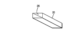
図2に、内部に反射壁26を具え、光経路20を形成する集光ロッドを示す。図4(a)〜図4(d)に示すように、鏡面の側壁はアパ−チャと反射偏光器30との間で光路27を形成する。反射偏光器は光の偏光を変換する手段である。図2(a)と図2(b)は、光源の像が集光器の中に効率よく注入されるように、集光ロッドの寸法が十分に大きく最適に選択される様子を示す。図3(a)と図3(b)に示すように、集光器の入力面が、十分な光を集光器の中に注入するのに十分な大きさの光注入孔(アパーチャ)18を有する反射面であれば、反射偏光器を集光器の端に据えることは容易である。その偏光器は、一方の成分(例えば、P偏光成分)を通過させると共に、他方の成分(例えば、S偏光成分)を反射して集光器の中に戻す。S偏光された光は、再び集光器の入力側に到達するので、そのうち一部は反射されて集光器の中に戻され、一部は注入孔から漏れ出る。反射されて光パイプの中に戻されたS偏光成分は、偏光が回転されてから反射偏光器に到達して二度目に偏光器を通過することができる。
FIG. 2 shows a condensing rod having a
図4(a)〜図4(d)は、本発明の構成を実行することができる4つの実施例を示す。図4(a)に示す実施例において、反射偏光器30は、モクステク(Moxtek)社製のプロフラックス(Proflux)である。これは、集光ロッドとその中に形成される光路27の長軸38に垂直に配置されると働くことが知られている非常に数少ない反射偏光器の1つである。偏光器で反射された光は、偏光を変換する手段(1/4波長板32)を二度通過することにより、リサイクル(recycle:回復)される。図4(a)において、1/4波長板32は反射偏光器と同じく、光路27の端に配置される。
FIGS. 4 (a) -4 (d) show four examples in which the configuration of the present invention can be implemented. In the embodiment shown in FIG. 4A, the
1/4波長板を、図4(b)に示すように、集光器の入力ポート(アパーチャ)18の付近に配置することもできる。反射偏光器と反対側の光路の端に1/4波長板を配置すると、出力ポートにおけるよりも光の減衰が減少する利点がある。図4(a)と図4(b)に好ましい実施例を示す。 A quarter-wave plate can also be placed near the input port (aperture) 18 of the collector, as shown in FIG. Placing a quarter-wave plate at the end of the optical path opposite the reflective polarizer has the advantage of reducing light attenuation than at the output port. A preferred embodiment is shown in FIGS. 4 (a) and 4 (b).
図4(c)と図4(d)は、偏光を反射する別のシステムを示す。集光器の鏡面26は偏光を回転させない誘電性コーティング、例えば、ユナクシス(Unaxis)社製のシルフレックス(Silflex)のコーティングとすることもできる。集光器はガラス製のロッドにすることもできる。出力の反射偏光器は出力ポートににかわ付けまたは他の方法で効果的に接着される。図4(c)と図4(d)で、反射偏光器は、図4(a)と図4(b)における単一の光学的装置とは対照的に、アセンブリ(assembly:組立て構体)である。図4(c)で、組立て構体は、別個の部品、すなわち、光路27の軸38に対して45°に配置される偏光ビーム・スプリッタ36と鏡(ミラー)34を具える。図4(d)で、組立て構体は、2個の部品(各々が光路27の軸に対して45°に、且つ互いに90°に配置される2個の偏光ビーム・スプリッタ40)を含んでいる。
Figures 4 (c) and 4 (d) show another system that reflects polarized light. The
光路の入力側にある光注入孔は、孔の有る反射コーティングで作ることもできる。遅延(retardation)フィルム42は、光路27内において、ロッドの出力面と反射偏光器との間に、またはロッドの入力部に配置される。図4(c)で、遅延フィルムは破線で表され、光路の入力端付近に配置され、図4(d)では、光路の出力付近に配置されている。図4(c)と図4(d)の各々において、遅延フィルムの位置は入力端から出力端へ、出力端から入力端へと、逆にすることもできる。
The light injection hole on the input side of the optical path can also be made of a reflective coating with holes. A
本発明の構成によるシステムは、以下の条件に従ってシミュレートされている。ランプは、放射イメージング16ビット型の汎用高圧放電ランプである。反射器は楕円形で、11.08x6.23mmの入力部を有する集光器の中に光を集める。集光器の側部は入射角と偏光と波長(Silflex鏡)に係りなく、光を98%反射する。反射偏光器はMoxtek社のProfluxであり、P偏光の透過率85%を有する。偏光器から反射されるS偏光は、集光器入力側に位置する1/4波長板により、効率85%でリサイクルされる。光注入孔の寸法(半径)を変え、システムの効率を注入孔の半径に対してプロットしている。図5のグラフは、最適の半径3.25mmが存在し、この半径の注入孔に対する効率は0.472であることを示している。この寸法の注入孔は、注入効率とリサイクルとの間の最良のトレードオフ(tradeoff:妥協の条件)である。注入孔がこれより小さければ、光パイプの中に注入される光は減少する。これより大きければ、Moxtek偏光器に反射後に漏れ出るS偏光は増加する。孔の半径が集光器の入力ポートの半対角線(semi‐diagonal)の寸法以上になれば、この照明システムがリサイクルをしないときの効率になる。これは、グラフから、孔の半径6.33mm以上で、0.323と読み取られる。従って、この形状で期待される利得は:G=0.472/0.323=1.46であり、これは非常によい値である。
The system according to the configuration of the present invention is simulated according to the following conditions. The lamp is a
このシステムを偏光ビーム・スプリッタ(Polarization Beam Splitter:PBS)の線形アレイに基づくシステムと比較すると、著しい利点は、極めてコンパクトであり、且つこのシステムは、集光器の出力をイメージャに結像するリレー(relay)レンズ系のほかに追加的な光学装置を必要としないので、形状をあまり変更せずに現行の設計に容易に適合できることである。その上、このようなリレー方式は、集光パイプを使用するシステムにおいて既に実現されている。このシミュレーションで使用されたもの(1.3mmのギャップを有する)よりも小さなバーナ(burner)を有する光源を用いてよりよい利得を達成することができる。このシステムで、新しく追加される部品は、ほんの少数で、フライ‐アイ(fly’s eye)レンズおよび偏光ビーム・スプリッタ・アレイの場合のように、大きなツーリング(tooling)を必要とせず、費用の点で有利である。 Comparing this system with a system based on a linear array of Polarization Beam Splitters (PBSs), the significant advantage is that it is very compact, and this system relays the output of the collector to the imager Since no additional optical device is required in addition to the (relay) lens system, it can be easily adapted to the current design without much change in shape. Moreover, such a relay system has already been realized in a system using a light collecting pipe. Better gain can be achieved with a light source having a smaller burner than that used in this simulation (with a 1.3 mm gap). With this system, only a few new parts are added, which does not require large tooling and cost as in the case of fly's eye lenses and polarizing beam splitter arrays. This is advantageous.
図5で、最大値1は光源の全光束である。半径6.33mm以上では、注入孔は集光器入力の寸法よりも大きいので出力は安定している。従って、偏光のリサイクルは無く、効率は約32.3%である。これは、光源から発せられる光の32.3%はイメージャを照明するのに利用でき、偏光されることを意味する。リサイクルすると、最良の値は、半径3.25mmで達成され、47.2%の偏光でピークとなり、利得は46%である。 In FIG. 5, the maximum value 1 is the total luminous flux of the light source. When the radius is 6.33 mm or more, the output is stable because the injection hole is larger than the size of the collector input. Therefore, there is no recycling of polarization and the efficiency is about 32.3%. This means that 32.3% of the light emitted from the light source can be used to illuminate the imager and is polarized. When recycled, the best value is achieved with a radius of 3.25 mm, peaking at 47.2% polarization and a gain of 46%.
Claims (25)
前記反射された光を更に反射して前記反射偏光器(30)の方へ戻すための少なくとも1つの反射面(26)と、
前記光経路内に配置されて、前記反射偏光器で反射された光を、前記第1の偏光を有する光に変換する変換手段と、から成り、前記変換された光も前記反射偏光器により伝送される、前記偏光回復システム。 In a polarization recovery system, an optical path having a light injection hole (18) for receiving light from an illumination source (12) that emits light having first and second polarizations (eg, P-polarization and S-polarization), The optical path (20) comprising a reflective polarizer (30) for transmitting the injected light having a first polarization and reflecting the injected light having a second polarization;
At least one reflective surface (26) for further reflecting the reflected light back towards the reflective polarizer (30);
Conversion means arranged in the optical path and converting light reflected by the reflective polarizer into light having the first polarization, and the converted light is also transmitted by the reflective polarizer Said polarization recovery system.
光路の長手方向の軸に平行に配置される鏡(ミラー)と、
前記軸に関して角度45°に配置される、偏光ビーム・スプリッタと、から成る、請求項1記載の偏光回復システム。 The reflective polarizer is
A mirror disposed parallel to the longitudinal axis of the optical path;
The polarization recovery system of claim 1, comprising a polarization beam splitter disposed at an angle of 45 ° with respect to the axis.
第1と第2の偏光を有する光を光路(27)に沿って前方に誘導するステップと、
前記第1の偏光を有する誘導された光を前記パスから通過させるステップと、
前記第2の偏光を有する光を前記光路に沿って後方と前方に反射するステップと、
前記反射するステップの間、反射された光を前記第1の偏光を有するように変換するステップと、
前記第1の偏光に変換された光を前記パスから通過させ、前記第1の偏光を有する光がより多く前記パスから通過できるようにするステップと、から成る、前記方法。 A method for recovering polarization in an illumination system (10) for a liquid crystal display (LCD) imager (24) comprising:
Directing light having first and second polarizations forward along the optical path (27);
Passing the guided light having the first polarization through the path;
Reflecting the light having the second polarization backward and forward along the optical path;
Converting the reflected light to have the first polarization during the reflecting step;
Passing the light converted to the first polarization from the path, and allowing more light having the first polarization to pass from the path.
ランダムに偏光される光の源(12)と、
前記ランダムに偏光された光を受け入れるために一方の端にアパーチャ(18)を具え且つ内部に光路(27)を形成する反射面(26)を具える、集光器(20)と、
前記光路の反対側の端に配置され、第1の偏光を有する光を伝送すると共に第2の偏光を有する光を反射する反射偏光器(30)であって、前記第2の偏光を有する光は前記光路に沿って前後に反射される、前記偏光器(30)と、
前記光路内に配置されて、前記前後に反射された光を、前記第1の偏光を有する光に変換する手段と、を具え、前記変換された光も前記反射偏光器により伝送される、前記照明システム。 An illumination system for a liquid crystal imager,
A randomly polarized light source (12);
A concentrator (20) comprising an aperture (18) at one end to receive the randomly polarized light and a reflective surface (26) forming an optical path (27) therein;
A reflective polarizer (30) disposed at the opposite end of the optical path for transmitting light having a first polarization and reflecting light having a second polarization, the light having the second polarization; Is the polarizer (30) reflected back and forth along the optical path;
Means for converting the light reflected back and forth disposed in the optical path into light having the first polarization, and the converted light is also transmitted by the reflective polarizer. Lighting system.
Applications Claiming Priority (2)
| Application Number | Priority Date | Filing Date | Title |
|---|---|---|---|
| EP01403044A EP1315022A1 (en) | 2001-11-27 | 2001-11-27 | Polarization recycler |
| PCT/US2002/037166 WO2003052489A1 (en) | 2001-11-27 | 2002-11-19 | Polarization recycler |
Publications (2)
| Publication Number | Publication Date |
|---|---|
| JP2005531792A true JP2005531792A (en) | 2005-10-20 |
| JP2005531792A5 JP2005531792A5 (en) | 2006-01-05 |
Family
ID=8182987
Family Applications (1)
| Application Number | Title | Priority Date | Filing Date |
|---|---|---|---|
| JP2003553318A Pending JP2005531792A (en) | 2001-11-27 | 2002-11-19 | Polarization recycling (recovery) equipment |
Country Status (7)
| Country | Link |
|---|---|
| EP (1) | EP1315022A1 (en) |
| JP (1) | JP2005531792A (en) |
| KR (1) | KR20040063152A (en) |
| CN (1) | CN100370312C (en) |
| AU (1) | AU2002366496A1 (en) |
| MX (1) | MXPA04004890A (en) |
| WO (1) | WO2003052489A1 (en) |
Families Citing this family (6)
| Publication number | Priority date | Publication date | Assignee | Title |
|---|---|---|---|---|
| EP1391776A1 (en) * | 2002-07-19 | 2004-02-25 | Sony International (Europe) GmbH | Light collecting, integrating and redirecting device |
| US7306344B2 (en) | 2003-06-10 | 2007-12-11 | Abu-Ageel Nayef M | Light guide array, fabrication methods and optical system employing same |
| EP1498773A1 (en) * | 2003-07-16 | 2005-01-19 | Thomson Licensing S.A. | Projection display apparatus |
| CN105805697A (en) * | 2006-06-13 | 2016-07-27 | 梅多星企业有限公司 | Illumination system and method for recycling light to increase the brightness of the light source |
| US8792070B2 (en) | 2007-03-21 | 2014-07-29 | Honeywell International Inc. | Polarization plate for use in a liquid crystal display |
| CN109323712A (en) * | 2018-12-04 | 2019-02-12 | 桂林聚联科技有限公司 | A kind of random polarization light source |
Family Cites Families (13)
| Publication number | Priority date | Publication date | Assignee | Title |
|---|---|---|---|---|
| US5816677A (en) * | 1905-03-01 | 1998-10-06 | Canon Kabushiki Kaisha | Backlight device for display apparatus |
| JPS63168626A (en) * | 1987-01-06 | 1988-07-12 | Citizen Watch Co Ltd | Liquid crystal display body |
| US6101032A (en) * | 1994-04-06 | 2000-08-08 | 3M Innovative Properties Company | Light fixture having a multilayer polymeric film |
| US6331879B1 (en) * | 1995-11-20 | 2001-12-18 | Minolta Co., Ltd. | Liquid crystal projector with an illumination optical system |
| TW359765B (en) * | 1996-05-10 | 1999-06-01 | Seiko Epson Corp | Projection type liquid crystal display apparatus |
| US6206532B1 (en) * | 1996-10-17 | 2001-03-27 | New Exciting Designs Limited | High efficiency light source projection apparatus |
| US5884991A (en) * | 1997-02-18 | 1999-03-23 | Torch Technologies Llc | LCD projection system with polarization doubler |
| JP3697013B2 (en) * | 1997-02-19 | 2005-09-21 | キヤノン株式会社 | Illumination device and projection device using the same |
| US6206463B1 (en) * | 1997-09-26 | 2001-03-27 | Jewel A. Whigham | Combined carrying case and folding seat |
| US6208463B1 (en) * | 1998-05-14 | 2001-03-27 | Moxtek | Polarizer apparatus for producing a generally polarized beam of light |
| US6064523A (en) * | 1998-06-29 | 2000-05-16 | International Business Machines Corporation | Apparatus for polarization conversion |
| US7052150B2 (en) * | 1999-12-30 | 2006-05-30 | Texas Instruments Incorporated | Rod integrator |
| US7070280B2 (en) * | 2001-07-04 | 2006-07-04 | Unaxis Balzers Aktiengesellschaft | Method for the generation of light of a given polarization state |
-
2001
- 2001-11-27 EP EP01403044A patent/EP1315022A1/en not_active Ceased
-
2002
- 2002-11-19 JP JP2003553318A patent/JP2005531792A/en active Pending
- 2002-11-19 WO PCT/US2002/037166 patent/WO2003052489A1/en active Application Filing
- 2002-11-19 AU AU2002366496A patent/AU2002366496A1/en not_active Abandoned
- 2002-11-19 MX MXPA04004890A patent/MXPA04004890A/en active IP Right Grant
- 2002-11-19 KR KR10-2004-7007520A patent/KR20040063152A/en not_active Application Discontinuation
- 2002-11-19 CN CNB028235649A patent/CN100370312C/en not_active Expired - Fee Related
Also Published As
| Publication number | Publication date |
|---|---|
| AU2002366496A1 (en) | 2003-06-30 |
| CN100370312C (en) | 2008-02-20 |
| KR20040063152A (en) | 2004-07-12 |
| CN1596379A (en) | 2005-03-16 |
| MXPA04004890A (en) | 2004-07-30 |
| EP1315022A1 (en) | 2003-05-28 |
| WO2003052489A1 (en) | 2003-06-26 |
Similar Documents
| Publication | Publication Date | Title |
|---|---|---|
| JP4994561B2 (en) | Polarization recovery system for projection display | |
| US6969177B2 (en) | Polarization recovery system using redirection | |
| US7529024B1 (en) | Polarization conversion system and illumination module | |
| US20050002169A1 (en) | Polarization recycler | |
| JP2007537461A (en) | Multiple lamp illumination system with polarization recovery and integration | |
| JP2005531792A (en) | Polarization recycling (recovery) equipment | |
| US20040032656A1 (en) | Polarization conversion system and method of calibrating same | |
| JP2005531792A5 (en) | ||
| JP2004534962A (en) | Image projection or display system | |
| KR100269690B1 (en) | Apparatus of illumination for liquid crystal projector | |
| JP2003059303A (en) | Illumination optical system and projection display device using it | |
| KR100744499B1 (en) | Illumination System in Liquid Crystal Projector | |
| JPH0894986A (en) | Liquid crystal projector | |
| US20060045456A1 (en) | Polarization conversion light pipe device | |
| WO2004077102A2 (en) | Polarization recovery system using redirection | |
| Li et al. | Novel projection engine with dual paraboloid reflector and polarization recovery systems | |
| JPH10161029A (en) | Polarization lighting device | |
| JPH08184800A (en) | Liquid crystal video projector |
Legal Events
| Date | Code | Title | Description |
|---|---|---|---|
| A521 | Request for written amendment filed |
Free format text: JAPANESE INTERMEDIATE CODE: A523 Effective date: 20051110 |
|
| A621 | Written request for application examination |
Free format text: JAPANESE INTERMEDIATE CODE: A621 Effective date: 20051110 |
|
| RD03 | Notification of appointment of power of attorney |
Free format text: JAPANESE INTERMEDIATE CODE: A7423 Effective date: 20060929 |
|
| RD04 | Notification of resignation of power of attorney |
Free format text: JAPANESE INTERMEDIATE CODE: A7424 Effective date: 20061120 |
|
| A521 | Request for written amendment filed |
Free format text: JAPANESE INTERMEDIATE CODE: A821 Effective date: 20080401 |
|
| RD02 | Notification of acceptance of power of attorney |
Free format text: JAPANESE INTERMEDIATE CODE: A7422 Effective date: 20080401 |
|
| RD04 | Notification of resignation of power of attorney |
Free format text: JAPANESE INTERMEDIATE CODE: A7424 Effective date: 20080415 |
|
| A131 | Notification of reasons for refusal |
Free format text: JAPANESE INTERMEDIATE CODE: A131 Effective date: 20081003 |
|
| A601 | Written request for extension of time |
Free format text: JAPANESE INTERMEDIATE CODE: A601 Effective date: 20081218 |
|
| A602 | Written permission of extension of time |
Free format text: JAPANESE INTERMEDIATE CODE: A602 Effective date: 20081226 |
|
| A521 | Request for written amendment filed |
Free format text: JAPANESE INTERMEDIATE CODE: A523 Effective date: 20090403 |
|
| A02 | Decision of refusal |
Free format text: JAPANESE INTERMEDIATE CODE: A02 Effective date: 20090519 |
|
| A521 | Request for written amendment filed |
Free format text: JAPANESE INTERMEDIATE CODE: A523 Effective date: 20090918 |
|
| RD13 | Notification of appointment of power of sub attorney |
Free format text: JAPANESE INTERMEDIATE CODE: A7433 Effective date: 20090925 |
|
| A521 | Request for written amendment filed |
Free format text: JAPANESE INTERMEDIATE CODE: A821 Effective date: 20090925 |
|
| A911 | Transfer to examiner for re-examination before appeal (zenchi) |
Free format text: JAPANESE INTERMEDIATE CODE: A911 Effective date: 20091027 |
|
| A912 | Re-examination (zenchi) completed and case transferred to appeal board |
Free format text: JAPANESE INTERMEDIATE CODE: A912 Effective date: 20100212 |