JP2005529031A - Container, container lid and method - Google Patents
Container, container lid and method Download PDFInfo
- Publication number
- JP2005529031A JP2005529031A JP2003532373A JP2003532373A JP2005529031A JP 2005529031 A JP2005529031 A JP 2005529031A JP 2003532373 A JP2003532373 A JP 2003532373A JP 2003532373 A JP2003532373 A JP 2003532373A JP 2005529031 A JP2005529031 A JP 2005529031A
- Authority
- JP
- Japan
- Prior art keywords
- container
- wall portion
- axis
- central longitudinal
- sealing surface
- Prior art date
- Legal status (The legal status is an assumption and is not a legal conclusion. Google has not performed a legal analysis and makes no representation as to the accuracy of the status listed.)
- Pending
Links
Images


Classifications
-
- B—PERFORMING OPERATIONS; TRANSPORTING
- B65—CONVEYING; PACKING; STORING; HANDLING THIN OR FILAMENTARY MATERIAL
- B65D—CONTAINERS FOR STORAGE OR TRANSPORT OF ARTICLES OR MATERIALS, e.g. BAGS, BARRELS, BOTTLES, BOXES, CANS, CARTONS, CRATES, DRUMS, JARS, TANKS, HOPPERS, FORWARDING CONTAINERS; ACCESSORIES, CLOSURES, OR FITTINGS THEREFOR; PACKAGING ELEMENTS; PACKAGES
- B65D51/00—Closures not otherwise provided for
- B65D51/16—Closures not otherwise provided for with means for venting air or gas
- B65D51/1633—Closures not otherwise provided for with means for venting air or gas whereby venting occurs by automatic opening of the closure, container or other element
- B65D51/1638—Closures not otherwise provided for with means for venting air or gas whereby venting occurs by automatic opening of the closure, container or other element by means of an element bursting upon a predetermined pressure in the container being exceeded
-
- B—PERFORMING OPERATIONS; TRANSPORTING
- B65—CONVEYING; PACKING; STORING; HANDLING THIN OR FILAMENTARY MATERIAL
- B65D—CONTAINERS FOR STORAGE OR TRANSPORT OF ARTICLES OR MATERIALS, e.g. BAGS, BARRELS, BOTTLES, BOXES, CANS, CARTONS, CRATES, DRUMS, JARS, TANKS, HOPPERS, FORWARDING CONTAINERS; ACCESSORIES, CLOSURES, OR FITTINGS THEREFOR; PACKAGING ELEMENTS; PACKAGES
- B65D41/00—Caps, e.g. crown caps or crown seals, i.e. members having parts arranged for engagement with the external periphery of a neck or wall defining a pouring opening or discharge aperture; Protective cap-like covers for closure members, e.g. decorative covers of metal foil or paper
- B65D41/32—Caps or cap-like covers with lines of weakness, tearing-strips, tags, or like opening or removal devices, e.g. to facilitate formation of pouring openings
- B65D41/46—Snap-on caps or cap-like covers
- B65D41/48—Snap-on caps or cap-like covers non-metallic, e.g. made of paper or plastics
-
- B—PERFORMING OPERATIONS; TRANSPORTING
- B65—CONVEYING; PACKING; STORING; HANDLING THIN OR FILAMENTARY MATERIAL
- B65D—CONTAINERS FOR STORAGE OR TRANSPORT OF ARTICLES OR MATERIALS, e.g. BAGS, BARRELS, BOTTLES, BOXES, CANS, CARTONS, CRATES, DRUMS, JARS, TANKS, HOPPERS, FORWARDING CONTAINERS; ACCESSORIES, CLOSURES, OR FITTINGS THEREFOR; PACKAGING ELEMENTS; PACKAGES
- B65D51/00—Closures not otherwise provided for
- B65D51/16—Closures not otherwise provided for with means for venting air or gas
- B65D51/1672—Closures not otherwise provided for with means for venting air or gas whereby venting occurs by manual actuation of the closure or other element
- B65D51/1688—Venting occurring during initial closing or opening of the container, by means of a passage for the escape of gas between the closure and the lip of the container mouth, e.g. interrupted threads
-
- B—PERFORMING OPERATIONS; TRANSPORTING
- B65—CONVEYING; PACKING; STORING; HANDLING THIN OR FILAMENTARY MATERIAL
- B65D—CONTAINERS FOR STORAGE OR TRANSPORT OF ARTICLES OR MATERIALS, e.g. BAGS, BARRELS, BOTTLES, BOXES, CANS, CARTONS, CRATES, DRUMS, JARS, TANKS, HOPPERS, FORWARDING CONTAINERS; ACCESSORIES, CLOSURES, OR FITTINGS THEREFOR; PACKAGING ELEMENTS; PACKAGES
- B65D51/00—Closures not otherwise provided for
- B65D51/24—Closures not otherwise provided for combined or co-operating with auxiliary devices for non-closing purposes
- B65D51/245—Closures not otherwise provided for combined or co-operating with auxiliary devices for non-closing purposes provided with decoration, information or contents indicating devices, labels
Abstract
密封容器(90)は、容器(100)と、この容器を一定範囲の内圧に渡って密封するための閉鎖部材(200)とを含んでいる。The sealed container (90) includes a container (100) and a closing member (200) for sealing the container over a certain range of internal pressure.
Description
本発明は、概して密封容器に関し、特に容器を密封するための閉鎖部材(蓋部材)に関する。 The present invention relates generally to a sealed container, and more particularly to a closure member (lid member) for sealing the container.
容器は様々な適用例に用いられている。特に1つの適用例としては、トニックウオーター、ソーダポップ、ビール等のような液体の貯蔵および流通がある。 Containers are used in various applications. One particular application is the storage and distribution of liquids such as tonic water, soda pop, beer and the like.
容器の1つの形式は瓶である。瓶は、例えばパリソン・ブロー成型、押出しブロー成型および射出成型を含む多くの製造工程によって製造され得る。飲料工業において一般に採用されてきた、そのような製造工程の1つが、ガラスのパリソン・ブロー成型である。 One type of container is a bottle. Bottles can be manufactured by a number of manufacturing processes including, for example, parison blow molding, extrusion blow molding and injection molding. One such manufacturing process that has been commonly employed in the beverage industry is glass parison blow molding.
瓶のような容器は一般に、閉鎖部材によって密封される。閉鎖部材は、数例を挙げるとコルク栓、王冠ないしツイスト・オフ・キャップのような様々な一般的要素である。一般に、ガラスの飲料容器は、王冠と呼ばれる閉鎖部材で密封される。王冠は従来、鋼鉄で構成されると共に、内部に設けられたライナーを有している。鋼鉄の王冠は、一般に型打ち金属加工工程で造られ、その後、さび止め処理がなされる。しばしばトップ・フィニッシュと呼ばれる瓶の最上面と、王冠との間のシール材としてライナーが設けられる。ライナーは一般に、軟質ウレタン、軟質プラスチック、ラテックス、ゴム、その他から製造される。 Containers such as bottles are generally sealed by closure members. Closure members are various common elements such as corks, crowns or twist-off caps, to name a few. Generally, glass beverage containers are sealed with a closure member called a crown. The crown is conventionally made of steel and has a liner provided inside. Steel crowns are generally made by stamped metal working, followed by rust prevention. A liner is provided as a seal between the top of the bottle, often called the top finish, and the crown. Liners are generally made from soft urethane, soft plastic, latex, rubber, and others.
従来のガラス瓶を密封するためには、まず充填後の瓶の頂部上へ王冠が配置される。そして、瓶の頂部の周囲で王冠が成形される(すなわち「曲げられる」)よう、王冠が瓶に対して押圧される。そのような次第で、ライナーがトップ・フィニッシュに対して圧迫され、これにより密封容器がもたらされる。 To seal a conventional glass bottle, a crown is first placed on the top of the bottle after filling. The crown is then pressed against the bottle so that the crown is molded (ie “bent”) around the top of the bottle. As such, the liner is squeezed against the top finish, thereby providing a sealed container.
一実施形態において、本発明の開示は、中心縦軸線と、この中心縦軸線と交差する第2軸線とを画定し、前記第2軸線が前記中心縦軸線に対して直角に延びているような容器を備え、この容器は、当該容器内の容器内側と、この容器内側に対して反対側に配置された容器外側と、前記容器内側と前記容器外側との間に液体の流通をもたらす開口と、少なくとも一部が、前記容器外側上に形成され前記第2軸線を横切って延びる第3軸線上にある第1密封面と、前記容器内側内に収容された一定量の液体と、前記開口を密封する閉鎖部材と、を含み、前記閉鎖部材は、第1壁部第1面を有する第1壁部と、この第1壁部から延びる、第2壁部第1面を有した第2壁部と、を備え、前記第2壁部第1面の少なくとも一部は、前記第1壁部に隣接し、前記第1壁部第1面の少なくとも一部は、前記一定量の液体に晒されており、前記一定量の液体は、その中に溶解された気体を含む、ことを特徴とする密封容器を含み得る。 In one embodiment, the present disclosure defines a central longitudinal axis and a second axis that intersects the central longitudinal axis, such that the second axis extends perpendicular to the central longitudinal axis. A container, and the container includes an inner side of the container, an outer side of the container disposed on the opposite side of the inner side of the container, and an opening that provides a liquid flow between the inner side of the container and the outer side of the container A first sealing surface on a third axis formed on the outer side of the container and extending across the second axis, a volume of liquid contained in the inner side of the container, and the opening. A first wall portion having a first wall portion first surface, and a second wall having a second wall first surface extending from the first wall portion. And at least part of the first surface of the second wall portion is adjacent to the first wall portion. At least a part of the first surface of the first wall portion is exposed to the fixed amount of liquid, and the fixed amount of liquid contains a gas dissolved therein. May be included.
もう1つの実施形態において、本発明の開示は、容器内側圧力にある容器内側を備えた密封容器のためのプラスチック製ネジなし閉鎖部材であって、第1壁部第1面と、この第1壁部第1面とは反対側に配置された第1壁部第2面とを有する第1壁部と、この第1壁部から延びる第2壁部であって、少なくとも一部が第3軸線上にある第2壁部第1面と、この第2壁部第1面に対して反対側に配置された第2壁部第2面とを有する第2壁部と、前記第2壁部の少なくとも一部に形成された螺旋状脆弱部と、を備え、前記第1壁部第1面は前記容器内側圧力に晒されている、ことを特徴とする閉鎖部材を含み得る。 In another embodiment, the present disclosure provides a plastic unthreaded closure member for a sealed container with a container inside at a container inside pressure, the first wall first surface, and the first A first wall portion having a first wall portion second surface disposed on the side opposite to the wall portion first surface, and a second wall portion extending from the first wall portion, at least a part of which is a third wall portion. A second wall portion having a second wall portion first surface on an axis and a second wall portion second surface disposed on the opposite side to the second wall portion first surface; and the second wall. And a helical fragile portion formed on at least a part of the portion, and the first wall portion first surface is exposed to the container inner pressure, and may include a closing member.
もう1つの実施形態において、本発明の開示は、容器を備えた密封容器であって、前記容器は、当該容器内の容器内側と、この容器内側に対して反対側に配置された容器外側と、前記容器内側と前記容器外側との間に液体の流通をもたらす開口と、前記容器外側上に形成された容器第1密封面と、前記容器内側内に収容された一定量の液体と、閉鎖部材第1面を有した、前記開口を密封する閉鎖部材と、を含み、当該密封容器は、少なくとも第1状態および第2状態を有し、前記第1状態においては、前記容器内側が第1圧力にあって、前記閉鎖部材第1面の少なくとも一部が、前記容器第1密封面の少なくとも一部に対して第1レベルの力を及ぼし、前記第2状態においては、前記容器内側が第2圧力にあって、前記閉鎖部材第1面の前記少なくとも一部が、前記容器第1密封面の前記少なくとも一部に対して第2レベルの力を及ぼし、前記第2圧力は前記第1圧力よりも大きく、前記第2レベルの力は前記第1レベルの力よりも大きい、ことを特徴とする密封容器を含み得る。 In another embodiment, the disclosure of the present invention is a sealed container including a container, wherein the container includes an inner side of the container and an outer side of the container disposed on the opposite side of the inner side of the container. , An opening for providing a liquid flow between the inside of the container and the outside of the container, a first sealing surface of the container formed on the outside of the container, a certain amount of liquid contained in the inside of the container, and a closure A closed member having a member first surface and sealing the opening, wherein the sealed container has at least a first state and a second state, and in the first state, the inside of the container is first. In pressure, at least a portion of the first surface of the closure member exerts a first level force on at least a portion of the first sealing surface of the container, and in the second state, the inner side of the container is the first level. At two pressures, the first surface of the closure member At least a portion exerts a second level force on the at least a portion of the container first sealing surface, the second pressure is greater than the first pressure, and the second level force is the first level. It may include a sealed container characterized by greater than one level of force.
もう1つの実施形態において、本発明の開示は、(a)中心縦軸線と、この中心縦軸線と交差する第2軸線とを画定し、前記第2軸線が前記中心縦軸線に対して直角に延びているような容器であって、当該容器内の容器内側と、この容器内側に対して反対側に配置された容器外側と、前記容器内側と前記容器外側との間に液体の流通をもたらす開口と、少なくとも一部が、前記容器外側上に形成され前記第2軸線を横切って延びる第3軸線上にある第1密封面と、を備えた容器を用意し、(b)第1壁部第1面を有する第1壁部と、この第1壁部から延びる、第2壁部第1面を有する第2壁部と、を備えた閉鎖部材を用意し、(c)前記容器内側の中に一定量の液体を計量分配し、(d)前記閉鎖部材を、前記容器と接するように移動させ、(e)前記第2壁部第1面の少なくとも一部を、前記第1密封面に対して密封状態で係合させ、(f)前記第1壁部第1面の少なくとも一部を、前記一定量の液体に対して晒す、ことを特徴とする容器の密封方法を含み得る。 In another embodiment, the present disclosure provides (a) defining a central longitudinal axis and a second axis intersecting the central longitudinal axis, the second axis being perpendicular to the central longitudinal axis. A container that extends, and provides liquid flow between the inside of the container, the outside of the container disposed on the opposite side of the inside of the container, and the inside of the container and the outside of the container A container having an opening and a first sealing surface at least partially formed on the outer side of the container and extending on a third axis extending across the second axis; and (b) a first wall. A closing member comprising a first wall having a first surface and a second wall having a second wall extending from the first wall and having a second wall; and (c) inside the container. Dispensing a constant amount of liquid therein; (d) moving the closure member into contact with the container; e) engaging at least a portion of the first surface of the second wall portion in a sealed state with the first sealing surface; and (f) engaging at least a portion of the first surface of the first wall portion with the fixed surface. A container sealing method characterized by exposing to an amount of liquid may be included.
図1に示すように、密封容器90は容器100と閉鎖部材200とを備え得る。説明的な目的のみのために、容器100は、ここでは瓶100と称される。また、説明的な目的のみのために、閉鎖部材200は、ここでは王冠200と称される。
As shown in FIG. 1, the sealed
更に図1に示すように、瓶100には、上部102、底部104、外周壁106およびネック120が設けられ得る。この瓶100の構成は、底部104付近でより大径で上部102付近ではより小径な円筒形の幾何学形状に帰着し得る。しかし、瓶は任意の様々な幾何学形状で製造され得る、ということが特記される。ネック120、外周壁106および底部104は、開口108(図5)、容器内側110(図5)および容器外側112を有する、比較的薄い壁で囲まれた物体を画定し得る。
As further shown in FIG. 1, the
瓶100は、プラスチックやガラスのような多くの合成物で造られ得る。図5に示すように、瓶100には、上部102において様々な形状構成が設けられ得る。瓶100には、以下でトップ・フィニッシュ122と称される最上部122と、第1密封面124と、以下でキャッチ密封面126と称される第2密封面とが設けられ得る。トップ・フィニッシュ122は、瓶100の上部102上に設けられている。開口108は、容器内側110と容器外側112との間で液体が流通できるようにするよう、トップ・フィニッシュ122を貫通して設けられている。第1密封面124は、瓶の上部102においてその外側112上に設けられ得る。この第1密封面124は、トップ・フィニッシュ122に隣接した円筒状の幾何学形状を有するように形成され得る。
The
トップ・フィニッシュ122から第1密封面124への遷移部に、瓶角部128が配置され得る。この瓶角部128は、図面においては図示の目的のために「鋭い」角部として示されているが、製造される際、瓶角部128のような瓶上の形状構成は一般に、製造上の関係によるアール形状や面取り形状を有する、ということが理解されるべきである。キャッチ密封面126は、第1密封面124の直下に設けられ得る。キャッチ密封面126は、トップ・フィニッシュ122と略平行で、第1密封面124に隣接していることができる。後に詳述するように、第1密封面124およびキャッチ密封面126は、代替実施形態においてテーパ角を有するように形成され得る。また、第1密封面124およびキャッチ密封面126の幾何学形状は、湾曲していてもよく、さもなければ、図面に示した実施形態から変更されていてもよい。例えば、密封面124,126は、凹状や凸状であってもよく、周状のリブや他の輪郭的なバリエーションを有していてもよい。
A bottle corner 128 may be disposed at the transition from the
本発明の装置の説明を補助するために、座標系が利用されている。この座標系は瓶100や王冠200の実際の物理的形状構成ではなく、説明的な目的のみのために利用される単なる道具である。この座標系は、中心縦軸線140(図1)を含み得る。図5に示すように、この中心縦軸線140は、第1方向144と、反対の第2方向142の両方向へ無限に延びる線である。説明を明瞭にするために、方向142をここでは上方向142と称し、方向144をここでは下方向144と称する。もちろん、これらの用語は瓶100の向きによって変わる相対的なものである、ということが理解される。上方向142と下方向144の両方向は、トップ・フィニッシュ122を起点としている。中心縦軸線140は、瓶100の仮想中心と一直線に合わせられている。そのような次第で、中心縦軸線140は、瓶100の近似的な中心軸線となっている。中心縦軸線140は、瓶100の境界を越えて延びているので、開口108の中心および底部104(図1)の中心を通って進んでいる。
A coordinate system is used to assist in the description of the apparatus of the present invention. This coordinate system is not an actual physical configuration of the
図5に示すように、座標系のもう1つの軸線が第2軸線150である。この第2軸線150は、中心縦軸線140と直交交点を形成するように交差する基準線である。例示に示すように、第2軸線150は瓶のトップ・フィニッシュ122と同一平面上にある。しかし、第2軸線150のこの位置は、説明的な目的のみのためにこの位置に設けられた例示的な交差位置である、ということが特記される。第2軸線150は、これに代わる任意の位置で中心縦軸線140と交差していてもよい。また、第2軸線150は、中心縦軸線140との交点から両方向へ無限に延びている。
As shown in FIG. 5, another axis of the coordinate system is the
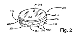
図5に示すように、密封容器90(図1)には王冠200が設けられる。この王冠200は、瓶の内側110を包むように保護するために利用される閉鎖装置であり、これにより容器内側110が外部環境から隔てられる。図2に示すように、王冠200には、第1壁部202と第2壁部204とが設けられている。説明的な目的のみのために、第1壁部202は以下で天板202と称される。また、第2壁部204は以下でスカート204と称される。天板202には、上面206、反対側に配置された第1壁部第1面208、および面取り角部210が設けられている。説明的な目的のみのために、第1壁部第1面208は以下で下面208(図5)と称される。上、下面206,208および面取り角部210は、瓶100のトップ・フィニッシュ122よりも僅かに大径な円盤状の幾何学形状を画定する。王冠200は、プラスチックを含む多くの材料のいずれかより製造され得る。王冠を製造し得る適当なプラスチックの例には、ポリエチレンおよびポリプロピレンが含まれる。
As shown in FIG. 5, a
図5に示すように、スカート204は、天板202の下面208上に設けることができる。スカート204は、瓶100の第1密封面124より僅かに大きい幾何学形状の略円筒形を画定し得る。スカート204には、第2壁部第1面220、反対側に配置された第2壁部第2面222、および底部224が設けられている。説明的な目的のみのために、第2壁部第1面220は以下でスカート内面220と称される。また、第2壁部第2面222は以下でスカート外面222と称される。スカート204には、第3壁部226が設けられ得る。説明的な目的のみのために、第3壁部226は以下でキャッチ(捕捉部)226と称される。このキャッチ226には、第3壁部第1面227が設けられ得る。キャッチ226は、内面220の全周における連続的な円周状の形状構成を形成し得る。スカート204には、更に傾斜部(ランプ)230が設けられ得る。この傾斜部230は、スカート底部224上の内側面取り部を形成し得る。
As shown in FIG. 5, the
図15に示すように、以下に傾斜部基準線232と称される第5軸線232を中心縦軸線140の回りに回転させることによって、傾斜部の基準的な幾何学形状が画定され得る。この傾斜部基準線232は、傾斜部頂点234において中心縦軸線140と交差する。傾斜部基準線232と中心縦軸線140との間の角度を示す、以下に傾斜部角度264と称される第3角度264が、図15に示されている。ランプ基準線232の回転は、その上に傾斜部230の少なくとも一部が存在するような平面を表して傾斜部の基準となる3次元幾何学形状を画定する。図示の例示においては、傾斜部角度264は約120度であるが、傾斜部角度264を任意の鈍角とし得る、ということが特記される。
As shown in FIG. 15, the reference geometric shape of the slope can be defined by rotating a
図2に示すように、スカート204には、更にリリース(解放部)250が設けられ得る。このリリース250は、スカート204上に設けられた形状構成によって画定され得る。そのような形状構成には、螺旋状脆弱部252、引裂き部254、結合部256およびタブ258が含まれ得る。説明的な目的のみのために、螺旋状脆弱部252は以下でスコア252と称される。このスコア252は、スカート204の外面222上に設けられ得る。
As shown in FIG. 2, the
図4の例示においては、スコア252はスカート204における溝部である。スコア252は、スカート204の壁厚を減少させ、これにより、スカート204とリリース250との間の分離部をもたらす。また、スコア252には、スカート204の底部224から延びる垂直部253(図9)が設けられ得る。図示の例示においては、スコア252は、円筒状に、またスカート204上を底部224から天板202に向かって上方向142へ垂直に、螺旋を描くように延びている。スコア252の少なくとも一部は、図4に示すように天板基準面268と交差するスコア基準面266上に配置され得る。引裂き部254は、スカート204の底部224付近に配置されてタブ258に結合され得る。結合部256は、リリース250の引裂き部254とは反対の側に配置され得る。後述するように、結合部256は、ひとたびスコア252がひき裂かれると、リリース250をスカート204に対して保持するのに役立つ。
In the illustration of FIG. 4, the
図5に示すようにして王冠200が瓶100上に取り付けられることで、密封容器90(図6)が製造される。充填作業中、開口108を通じて瓶100の内側110へ液体が計量分配される。瓶100内へ計量分配され得る液体は、様々な液体のいずれかとすることができる。そのような液体は、水溶液とすることができ、或いはその中に含有される気体を含むこともできる。気体を含有した液体には、炭化ガス、不活性ガスないし酸化ガスのような様々な気体のいずれかが含まれ得る。瓶100内に十分な量の液体が計量分配されたら、その瓶100に対して王冠200が取り付けられる。瓶100に対して王冠200を取り付けることで、密封容器90がもたらされる。
As shown in FIG. 5, the
さらに図5に示すように、スカート底部224を瓶100のトップ・フィニッシュ122へ隣接するように位置決めすることで、瓶100に対する王冠200の取り付けが行われる。王冠200は、傾斜部230が瓶角部128に接触するまで下方向144へ移動する。王冠200は下方向144へ押圧され、これによりスカート204の撓みが引き起こされる。スカート204は、その外周が一時的に拡大するように撓み、これによりキャッチ226は瓶角部128を通過することができる。さらに下方向144へ移動する間、キャッチ226は第1密封面124上を摺動する。天板202の底部(下面)208がトップ・フィニッシュ122に接するまで王冠200が移動したら、図6に示すように、キャッチ226がキャッチ密封面126と「スナップ式に係合」する。
Further, as shown in FIG. 5, the
スカート204の撓みは、王冠200の成型材料の機械的特性と本明細書に開示された設計とによって生じるものである。王冠200の取り付けは、王冠200自身に対して自らの形状を実質的に変えないような力を及ぼすものである、ということに注目することが重要である。従って、その取付け力は、王冠200の永久変形を引き起こす力よりも小さい(すなわち、その力は材料の弾性限度よりお小さい)。そのような次第で、王冠200は、瓶100上に「スナップ式に取り付け」された後においも、製造時と同様の寸法を保つ。
The deflection of the
密封容器90は、輸送用に包装されると目的地へ配送される。後の議論のため、流通によって密封容器90の撹拌および/または温度上昇が生じ得る、ということに注目することが重要である。密封容器90の撹拌および温度上昇は、液体、特にソーダポップ、トニックウオーター、ビール、セルツア炭酸水等のような気体を含有した液体における内圧(内部圧力)の上昇という結果を招く。そのような次第で、密封容器90は内圧の変動に対する相当の許容量を要する。従って、密封容器90は、その内部に収容した液体が漏れたり駄目になったりしないことを確保するために、一定範囲の圧力に渡る密封をもたらし得る。
When the sealed
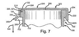
充填および流通後のある時点で、密封容器90は消費者によって開けられる。図8に示すように、密封容器90を開けるために、消費者は王冠200上のタブ258を引っ張る。タブ258を引っ張ることで、スコア252が破れて、リリース250の引裂き部254がスカート204から分離する。図7に示すように、リリース250の分離によって、キャッチ226の一部がキャッチ密封面126との係合から外れるように移動する。キャッチ226がもはやキャッチ密封面126と係合していないので、密封容器90内の内圧が瓶100から逃げはじめ得る。
At some point after filling and distribution, the sealed
図9に示すように、タブ258をさらに引っ張ることで、スコア252におけるリリース250の分離が結合部256まで継続される。スコア252をさらに引っ張っている間、リリース250はスカート204からさらに分離され、瓶100内に残っている内圧が全て解放され得る。リリース250が結合部256でスカート204へヒンジ式に結合されているだけの状態になると、王冠200全体が瓶100から取り外され得る。王冠200が瓶100から完全に取り外されたとき、リリース250はスカート204に結合されたままである。王冠200が瓶100から取り外されることで、その中の内容物が開口108を通じて使用可能となる。
As shown in FIG. 9, by further pulling the
スコア252の螺旋形状が、図9に示すような制御された解放を可能とするスカート内面220の吹出し誘導部221をもたらす、ということに注目することが重要である。圧力の制御された解放は、圧力、液体および/または泡の下方向144への解放を可能とする。そのような次第で、密封容器90が開けられるときに、圧力、液体および/または泡の解放が消費者に向けられないようにすることができる。圧力、液体および/または泡は、消費者へ吹き出す代わりに、吹出し誘導部221と第1密封面124との間で下方向144へ誘導される。図7に示すように、この制御された圧力の解放は、内圧、液体および/または泡が容器内側110から逃げ出すという結果につながる。この内圧は、トップ・フィニッシュ122と天板底部(下面)208との間を通過する。トップ・フィニッシュ122を通過した後、内圧は瓶角部128を通過して逃げ出し続ける。瓶角部128を通過した後、内圧は、第1密封面124の吹出し誘導部221とスカート内面220との間を移動して行く。吹出し誘導部221を通過した後、内圧、液体および/または泡は、下方向144へ誘導される。
It is important to note that the spiral shape of the
密封容器の状態
上述したように、密封容器90は、例えば撹拌や温度上昇による、内圧の変動を被り得る。ここでは、その内圧の様々な例示的段階を説明する。図10〜13に示すように、密封容器90における容器外側に存在する周囲圧力に対しての内圧の強弱(ダイナミクス)を詳細に示すために、任意目盛(arbitrary scale)80が利用されている。この任意目盛80は、密封容器90の最大圧力許容量を表す0〜100パーセントの範囲を示す。図10に示す状態において、瓶内には周囲状態(すなわち外部状態)に対しての圧力は存在しておらず、従って、目盛は最大許容量のゼロパーセントの読みを示している。一方、図13は、密封容器90の内圧が殆ど最大圧力許容量に達している状態を描いており、従って、目盛80は最大許容量の90パーセントの読みを示している。ビールのような飲料を含む、瓶100のような容器は、約10psi(ポンド毎平方インチ)から100psiまで変化する内圧を有し得るということが定められている。
State of Sealed Container As described above, the sealed
説明を明瞭にするために、表面に作用して力を生じさせる圧力の物理的原理を説明する。力は(単位が合っていると仮定すれば)表面積に圧力を掛けた積である。圧力にさらされる表面(例えば天板底部(下面)208)は、前記の等式に従って力に帰することができる。実例を用いれば、天板底部(下面)208が例えば1.2平方インチの表面積を有すると共に外圧よりも20psiだけ高い内圧にさらされる場合、天板202は上方向142へ24ポンドの力を受けるであろう。もう1つの例においては、スカート204上に作用する内圧から生じる力は、第1密封面124と接していないスカート内面220の表面積に、内圧と外圧との間の圧力差を乗じることによって定められる。
For the sake of clarity, the physical principle of pressure acting on the surface and creating a force is described. The force is the product of the surface area plus pressure (assuming the units are correct). A surface exposed to pressure (eg, the top (bottom surface) 208) can be attributed to a force according to the above equation. By way of example, if the top plate bottom (bottom surface) 208 has a surface area of, for example, 1.2 square inches and is exposed to an internal pressure that is 20 psi higher than the external pressure, the
適用される任意目盛80、および表面に作用して力を生み出す圧力の原理への導入をもたらしたところで、ここに複数の異なる状態の詳細な説明を提示することにする。
Given the introduction of the
ゼロ圧力状態
図10に示すように、ゼロ圧力状態は、王冠200が瓶100へしっかり取り付けられて、内圧と外圧との間に差のない密封容器90を形成している場合に存在する。任意目盛80に示すように、内圧は本質的に最大許容量のゼロパーセントである。上述したように、この状態は一般的に、充填および王冠200の取り付けの直後に生じる。この状態においては、第1密封面124とスカート内面220との間の境界面、およびキャッチ密封面126とキャッチ226との間の境界面が密封面である。
Zero Pressure State As shown in FIG. 10, the zero pressure state exists when the
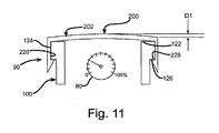
天板膨出状態
図11に示す天板膨出状態の間、容器内には、天板202の膨出を招くような内圧の第1の大きさが存在する。任意目盛80に示すように、圧力はごく小さく、例えば最大許容量の25パーセントである。天板202はD1の距離だけ膨出し得る。天板202が膨出するのは、天板底部(下面)208の表面積が内圧にさらされる結果として、上述した原理に従って発生する力のせいである。この状態においては、第1密封面124とスカート内面220との間の境界面、およびキャッチ密封面126とキャッチ226との間の境界面が密封面である。
The top plate bulge state During the top plate bulge state shown in FIG. 11, a first magnitude of internal pressure that causes the
スカート降伏状態
天板膨出状態よりも少し高い内圧においては、図12に示すようなスカート降伏状態が生じ得る。図12の任意目盛80に示すように、内圧は、天板膨出状態よりも少し高く、例えば最大許容量の55パーセントである。スカート降伏状態は、距離D2だけスカート204が伸長するという結果につながる。このスカートの降伏は、内圧によって天板底部(下面)208に加えられる力によるものである。この力は、スカートを、その降伏(すなわち「引き延ばし」)を生じさせる張力の下に置くのである。スカート降伏状態の間、第1密封面124とスカート内面220との間の境界面、およびキャッチ密封面126とキャッチ226との間の境界面が密封面である。
Skirt Yield State At a slightly higher internal pressure than the top plate bulge state, a skirt yield state as shown in FIG. 12 can occur. As shown in the
スカート膨出状態
スカート降伏状態よりも少し高い内圧においては、図13に示すようなスカート膨出状態が生じ得る。図13の任意目盛80に示すように、内圧は、スカート降伏状態よりも少し高く、例えば最大許容量の90パーセントである。スカート膨出状態は、スカート204が半径方向に距離D3だけ引き延ばされるという結果につながる。本質的に、スカート204の直径が増大するのである。このスカート膨出状態の間、内圧がスカート内面220に作用する。このスカート内面220に作用する内圧がスカートを半径方向に押す。従って、スカート内面220と瓶の第1密封面124とが接触しなくなるので、それらの間の密封がゼロまで減少し得る。スカート膨出状態の間、キャッチ密封面126とキャッチ226との間、より特定的にはキャッチ密封面126と第3壁部第1面227との境界面が密封面である。
Skirt bulging state At an internal pressure slightly higher than the skirt yielding state, a skirt bulging state as shown in FIG. 13 can occur. As shown by the
容器状体の総括
瓶100内の圧力が増大するに連れて、密封をもたらす表面が移り変わって行く。ここで、瓶100の内圧がゼロから100psiまで増大するような事例を、発生する密封特性との関係で説明する。ゼロ圧力状態(図10)では、第1密封面124とスカート内面220との間の接触によって瓶が密封されている。外部の周囲圧力に対して瓶内の圧力が増大するに連れて、図11に描かれた天板膨出状態に示したように、天板202が膨出し始めるであろう。天板202の内側部分(下面)208が、天板202の膨出を招くような内圧にさらされるのである。この天板膨出状態においては、天板202に加わる力が、キャッチ密封面126とキャッチ226との間の増大する接触力によって対抗される。
Container Summary As the pressure in the
瓶100内の圧力が増大し続けると、図12に示したようなスカート降伏状態の間、スカート204が降伏するであろう。このスカート降伏状態は、スカート204の外力許容特性を超える力を引き起こすような、天板底部(下面)208に作用する内圧が招いた結果である。そのような次第で、スカート204が距離「D2」(図12)だけ降伏する(引き延ばされる)。天板202に作用する力が増大しているので、その結果生じるキャッチ密封面126とキャッチ226との間の接触力も増大する。スカート降伏状態の間、第1密封面124とスカート内面220との間の接触によって瓶100が密封される。
As the pressure in the
圧力が増大し続けると、スカート204は、スカート内面220と第1密封面124との間の接触を維持する自らの能力を超えた内圧にさらされるであろう。瓶100の内圧が、第1密封面124とスカート内面220との間の接触力よりも大きい力を発生させると、図13のスカート膨出状態に示したようにスカート204が半径方向に撓む。このスカート膨出状態におけるスカート204の撓みが、図13で距離「D3」として描かれている。スカート膨出状態の間、内圧によって引き起こされる力の増大の結果として、キャッチ密封面126とキャッチ226との間の接触圧力が増大し続ける。また、スカート膨出状態の間、キャッチ密封面126とキャッチ226との間の接触によって瓶100が密封される。
As the pressure continues to increase, the
代替的な実施形態
テーパ状密封面
本発明の装置は少なくとも1つのテーパ状密封面によって性能が向上する、ということが見出されている。テーパ状にされ得る1つの密封面は、第1密封面124である。テーパ状にされ得るもう1つの密封面は、キャッチ密封面126である。図14〜図17は、様々なテーパ状密封面を示している。図14〜図17に示すテーパ状密封面の角度は図示の目的のために誇張されている、ということが特記される。
Alternative embodiments
Tapered sealing surface It has been found that the device of the present invention improves performance with at least one tapered sealing surface. One sealing surface that can be tapered is a
図14に示すように、王冠200と瓶100との間の密封力を増大させるためにテーパ状の第1密封面124を設けることができる。この第1密封面124は、トップ・フィニッシュ122とキャッチ密封面126とで異なる2つの直径を有し得る。第1密封面124は、トップ・フィニッシュ122付近でより大きい直径を、キャッチ密封面126付近でより小さい直径を有し得る。この代替的な実施形態においては、スカート204に、第1密封面124のテーパと本質的に適合する傾斜した内面220が設けられ得る。この第1密封面124のテーパは、第3軸線226を中心縦軸線140の回りに回転させることによって画定されるスカート密封基準形状で描写される。記述の目的のみのために、第3軸線226は以下でスカート密封基準線226と称される。このスカート密封基準線226は、以下でスカート頂点228と称される第1頂点228において中心縦軸線140と交差し得る。図14には、スカート密封基準線226と中心縦軸線140との間の角度を表す、以下でスカート角度229と称される第1角度229が示されている。スカート密封基準線226の回転によって、その上に第1密封面124の少なくとも一部が属するような平面である、3次元のスカート密封基準形状が形成される。
As shown in FIG. 14, a tapered
天板202の下面208上に作用する内圧の増大は、天板202および、それに影響を及ぼすように付随した全ての形状構成を上方向142へ移動させる。天板202の移動は、スカート204の上方向142への伸長および移動につながる。このスカート204の伸長および移動は、第1密封面124とスカート内面220との間の接触圧を増大させる。この接触圧の増大は、増大された密封という結果をもたらす。この代替的実施形態においては、スカート角度229を任意の鋭角とすることができる。しかし、スカート角度229は、随意に20度未満、より好ましくは約1〜4度、最も好ましくは約2度とすることができる。
The increase in internal pressure acting on the
図15に示すように、王冠200の密封力を増大させるためにテーパ状の第2密封面126を設けることができる。この第2密封面126も、キャッチ密封面126と称される。このキャッチ密封面126は、自らとキャッチ226との間の接触のための表面積を最小限にするよう、傾斜を付けることができる。この代替的実施形態においては、キャッチ密封面126が、図16に示すスカート膨出状態において王冠200の輪郭と合うように角度が付けられている。図16に示すように、このキャッチ密封面126のテーパは、天板202に作用する圧力の増大に応じた、キャッチ密封面126とキャッチ226との間の接触圧の増大という結果をもたらし得る。
As shown in FIG. 15, a tapered
以下でキャッチ密封基準線270と称する第4基準線270を中心縦軸線140の回りに回転させることによって、キャッチ密封基準形状が画定され得る。このキャッチ密封基準線270は、キャッチ頂点272において第2軸線150と交差する。図15には、キャッチ密封基準線270と第2軸線150との間の角度を表す、以下でキャッチ角度274と称される第2角度274が示されている。キャッチ密封基準線270の回転によって、その上にキャッチ密封面126の少なくとも一部が属するような平面である、3次元のキャッチ密封基準形状が形成される。図示の例示においては、キャッチ角度274は任意の鋭角とすることができる。しかし、キャッチ角度274は、20度未満、より好ましくは約1〜4度、最も好ましくは約2度とすることができる。
By rotating a
図16に示す最大圧力状態(スカート膨出状態)における王冠200の輪郭と合わせるようにすることで、スカート204およびキャッチ226に加わる曲げ応力を最小限にすることができる。また、キャッチ密封面126に角度を付けることで、密封に対して、キャッチ226とキャッチ密封面126との間の最大表面積が与えられる。瓶100内部の内圧上昇は、キャッチ226とキャッチ密封面126との間の表面積に、上述した原理による接触圧の増大を受けさせるのである。
The bending stress applied to the
さらに図15には、テーパ状の第1密封面124とテーパ状のキャッチ密封面126とを有する例示が示されている。テーパ状の第1密封面124は、低圧では密封をもたらすが、高圧では必ずしも密封をもたらすものではない。従って、高圧での密封をもたらすためにキャッチ密封面126が利用されている。即ち、キャッチ密封面126は、高圧にある容器90を密封する能力を備えている。そのような次第で、上述した原理により、第1密封面124が低圧での密封をもたらし、キャッチ密封面126が高圧での密封をもたらすのである。
Further, FIG. 15 shows an example having a tapered first sealing
圧力軽減機構
上述したように、密封容器90は、その内圧の上昇を引き起こすような状態を被り得る。そのような状態は、例えば容器の撹拌や温度上昇を含み得る。これらによる密封容器90の内圧変動を最大限、制限するために、圧力軽減(逃がし)機構を設けることができる。この圧力軽減機構は、内圧を所定の圧力、例えば100psiに制限し得る。瓶100は、100psiを超える、例えば150psiの圧力で損なわれ得るという理由で、その内圧を制限することが要求され得る。そのような次第で、瓶100が損なわれる前に、王冠200、即ち圧力軽減機構が内圧を逃がし得ることを確保するための安全マージンを設けることができる。
Pressure Relief Mechanism As described above, the sealed
内圧の最大値を制限するための1つの機構は、図17に示すように、密封容器90内の圧力が所定の最大値に達した時に解放される部分をスコア252に設けることである。裂けたスコア252は、開封されて消費不能な製品にはつながるが、圧力を制限することは確保してくれる。また、この圧力軽減機構は、消費者に対して視覚的に明らかとなり得る。他の圧力軽減機構も熟慮されており、それを代替的に組み込むことも可能である。1つの例は、キャッチ226上に形成される脆弱部分である。もう1つの例としては、スコアに類似した形状構成をスカート204や天板202上に設けることができる。例えば、スカート204上に中心縦軸線140と平行に真っ直ぐな溝を設けてもよい。
One mechanism for limiting the maximum value of the internal pressure is to provide a portion in the
押込み作動式タブ
図18および図19に示すもう1つの代替的実施形態においては、タブ258を引っ張り作動ではなく、押込み作動させることができる。この代替的実施形態においては、タブ258に、さらに片持梁状部分280および支点部分282が設けられ得る。図19に示すように、片持梁状部分280を押すことで、タブ258が支点部分282の回りに回動する。このタブ258の回動がスコア252に対して応力を加える。このスコア252に対する応力がスコア252の強度を超えるや否や、これによって解放部250が引裂き部254においてスカート204から部分的に解き放たれる。この代替的実施形態の変形例においては、支点部分282を省略することができる。この変形例では、片持梁状部分280を押すことでキャッチ226の回りでの回動を生じさせ、これによりスカート204からのスコア252の解放を生じさせる。
Push-Activated Tab In another alternative embodiment shown in FIGS. 18 and 19, the
リブ付きスカート
図20および図21に示すもう1つの代替的実施形態においては、スカート204に、リブ290,292のような複数のリブを設けることができる。これらのリブ、例えばリブ290は、スカート204に対して追加的な厚さをもたらし、スカート膨出状態(図13)の間、スカート204の膨出を最小限にすることができる。また、王冠200に対して金属仕上げを加えることもできる。
Ribbed Skirt In another alternative embodiment shown in FIGS. 20 and 21, the
ライナー
もう1つの代替的実施形態においては、王冠200のスカート内面220と天板下面208上にライナー(図示せず)を設けることができる。このライナーは、密封をもたらすための適当な材料で出来た薄い層とすることができる。ライナーは、軟質ウレタン、軟質プラスチック、ラテックス、ゴム等とすることができる。ライナーは、何らかの不完全性が存在するであろう第1密封面124やキャッチ密封面126のような密封面のいずれかに、追加的な密封をもたらし得る。また、ライナーは、密封容器90の内側110に存在するあらゆる酸素を消滅させるのに役立てられる脱酸素剤を備えていてもよい。この代替的実施形態の変形例においては、王冠を低硬度の材料で製造すると共に、王冠の内部に脱酸素剤を備えることができる。
Liner In another alternative embodiment, a liner (not shown) can be provided on the skirt
スコアの幾何学形状
もう1つの代替的実施形態においては、スコア252(図2)に対して変更された幾何学形状を与えることができる。この代替的実施形態においては、スコア252が変化する厚さを有することができ、これによりスコア252を破るのに要する力が変化し得る。そのような次第で、スコア252の引裂き部254に近い部分が、スコア252の結合部256に近い部分よりも容易に破られるようにすることができる。この変化する幾何学形状によって、瓶100内に含まれる内圧が制御されたやり方で解放されることを確保することができる。制御されたやり方での圧力の解放によって、圧力を、スカート内面220と第1密封面124との間で下方向144に向けることができる。
Score Geometry In another alternative embodiment, a modified geometry can be provided for score 252 (FIG. 2). In this alternative embodiment, the
印 字
図21に示すもう1つの代替的実施形態においては、王冠天板202の上面206に印字300を施すことができる。そのような印字300は、操作の説明やリサイクルの指示を含み得る。さらに、印字300は、販売される商品の出所を提供し得る。
Printing In another alternative embodiment shown in FIG. 21, a
本発明の容器を密封するための装置および方法は、瓶100のような容器を密封するための費用的効果に優れた解決手段をもたらす。閉鎖部材200は、従来の材料を超える多くの利点を有した材料から製造し得る。特に、王冠200のようなプラスチック製の閉鎖部材は、従来の鋼鉄製の王冠と同じように環境状態の影響を受けやすくはない。さらに、瓶100は触感に優しいデザインを有し、これによって消費者の受け入れやすさが改善される。この触感に優しい瓶100のデザインは、いかなるネジ山やその他の突起も有していないのである。
The apparatus and method for sealing a container of the present invention provides a cost effective solution for sealing a container such as
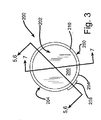
図示の例示においては、王冠200および瓶100の幾何学形状が円形に描かれている。例示した密封容器90の説明および図面は円形の幾何学形状に向けられているが、この幾何学形状は変形され得る、ということが特記される。例えば、八角形、四角形ないし三角形がある。また、図面では本発明の装置を丸み付けや面取りなしで描いている、ということが特記される。瓶角部128(図5)のような、瓶100および王冠200の種々の角部は、鋭い角を避けるために丸み付けを有することができる。
In the illustrated example, the geometric shapes of the
Claims (24)
この容器は、
当該容器内の容器内側と、
この容器内側に対して反対側に配置された容器外側と、
前記容器内側と前記容器外側との間に液体の流通をもたらす開口と、
少なくとも一部が、前記容器外側上に形成され前記第2軸線を横切って延びる第3軸線上にある第1密封面と、
前記容器内側内に収容された一定量の液体と、
前記開口を密封する閉鎖部材と、
を含み、
前記閉鎖部材は、
第1壁部第1面を有する第1壁部と、
この第1壁部から延びる、第2壁部第1面を有した第2壁部と、
を備え、
前記第2壁部第1面の少なくとも一部は、前記第1壁部に隣接し、
前記第1壁部第1面の少なくとも一部は、前記一定量の液体に晒されており、
前記一定量の液体は、その中に溶解された気体を含む、ことを特徴とする密封容器。 A container defining a central longitudinal axis and a second axis intersecting the central longitudinal axis, the second axis extending at right angles to the central longitudinal axis;
This container
Inside the container,
The outside of the container disposed on the opposite side to the inside of the container;
An opening that provides liquid flow between the inside of the container and the outside of the container;
A first sealing surface at least partially on a third axis formed on the outside of the container and extending across the second axis;
A certain amount of liquid contained inside the container;
A closing member for sealing the opening;
Including
The closure member is
A first wall portion having a first wall portion first surface;
A second wall portion having a second wall portion first surface extending from the first wall portion;
With
At least a portion of the first surface of the second wall is adjacent to the first wall;
At least a part of the first surface of the first wall portion is exposed to the certain amount of liquid,
The sealed container characterized in that the certain amount of liquid contains a gas dissolved therein.
前記容器は、前記第3軸線と前記中心縦軸線との交点に位置する第1頂点を更に画定しており、
前記第1頂点は、前記開口から前記第1方向にある、ことを特徴とする請求項1記載の密封容器。 The container further defines a first direction extending from the opening toward the container interior along the central longitudinal axis;
The container further defines a first vertex located at the intersection of the third axis and the central longitudinal axis;
The sealed container according to claim 1, wherein the first apex is in the first direction from the opening.
前記第1角度は10度未満である、ことを特徴とする請求項2記載の密封容器。 The container further defines a first angle formed between the first sealing surface and the central longitudinal axis;
The sealed container according to claim 2, wherein the first angle is less than 10 degrees.
この第2密封面の少なくとも一部は、前記容器外側上に形成され前記中心縦軸線を横切って延びる第4軸線上にあり、
前記閉鎖部材は、前記第2壁部から延びる第3壁部を更に備え、
この第3壁部は、第3壁部第1面を有し、
前記第3壁部第1面の少なくとも一部は、前記第2密封面に隣接している、ことを特徴とする請求項1記載の密封容器。 The container further comprises a second sealing surface,
At least a portion of the second sealing surface is on a fourth axis formed on the outside of the container and extending across the central longitudinal axis;
The closure member further includes a third wall portion extending from the second wall portion,
The third wall portion has a third wall portion first surface,
The sealed container according to claim 1, wherein at least a part of the first surface of the third wall portion is adjacent to the second sealed surface.
前記第2角度は鋭角である、ことを特徴とする請求項4記載の密封容器。 The container further defines a second angle formed between the fourth axis and the second axis;
The sealed container according to claim 4, wherein the second angle is an acute angle.
前記容器内側は、内部圧力にあり、
前記内部圧力は、前記周囲圧力より少なくとも10psiだけ高い、ことを特徴とする請求項1記載の密封容器。 The outside of the container is at ambient pressure;
The inside of the container is at internal pressure;
The sealed container of claim 1, wherein the internal pressure is at least 10 psi higher than the ambient pressure.
第1壁部第1面と、この第1壁部第1面とは反対側に配置された第1壁部第2面とを有する第1壁部と、
この第1壁部から延びる第2壁部であって、少なくとも一部が第3軸線上にある第2壁部第1面と、この第2壁部第1面に対して反対側に配置された第2壁部第2面とを有する第2壁部と、
前記第2壁部の少なくとも一部に形成された螺旋状脆弱部と、
を備え、
前記第1壁部第1面は前記容器内側圧力に晒されている、ことを特徴とする閉鎖部材。 A plastic screwless closure for a sealed container with a container inside at container inside pressure,
A first wall portion having a first wall portion first surface and a first wall portion second surface disposed on the opposite side of the first wall portion first surface;
A second wall extending from the first wall, the second wall having a first surface at least partially on the third axis, and disposed opposite to the first surface of the second wall. A second wall portion having a second wall portion second surface;
A spiral fragile portion formed on at least a part of the second wall portion;
With
The closing member according to claim 1, wherein the first surface of the first wall is exposed to the pressure inside the container.
前記第3軸線と前記中心縦軸線との交点に位置する第1頂点と、
を画定し、
前記第1頂点は、前記第1壁部第1面から前記第1方向にある、ことを特徴とする請求項7記載のプラスチック製ネジなし閉鎖部材。 A first direction extending from the first wall portion first surface so as to move away from the first wall portion second surface along a central longitudinal axis;
A first vertex located at the intersection of the third axis and the central longitudinal axis;
Define
8. The plastic screwless closing member according to claim 7, wherein the first apex is in the first direction from the first surface of the first wall portion.
前記第1角度は10度未満である、ことを特徴とする請求項8記載のプラスチック製ネジなし閉鎖部材。 The container further defines a first angle formed between the first surface of the second wall and the central longitudinal axis;
9. The plastic screwless closure according to claim 8, wherein the first angle is less than 10 degrees.
前記容器は、第4軸線と前記第2軸線との間に形成される第2角度を更に画定しており、前記第2角度は鋭角である、ことを特徴とする請求項10記載のプラスチック製ネジなし閉鎖部材。 The closure member further defines a second axis extending perpendicular to the central longitudinal axis;
The plastic container of claim 10, wherein the container further defines a second angle formed between a fourth axis and the second axis, and the second angle is an acute angle. Screwless closure member.
前記容器は、
当該容器内の容器内側と、
この容器内側に対して反対側に配置された容器外側と、
前記容器内側と前記容器外側との間に液体の流通をもたらす開口と、
前記容器外側上に形成された容器第1密封面と、
前記容器内側内に収容された一定量の液体と、
閉鎖部材第1面を有した、前記開口を密封する閉鎖部材と、
を含み、
当該密封容器は、少なくとも第1状態および第2状態を有し、
前記第1状態においては、前記容器内側が第1圧力にあって、前記閉鎖部材第1面の少なくとも一部が、前記容器第1密封面の少なくとも一部に対して第1レベルの力を及ぼし、
前記第2状態においては、前記容器内側が第2圧力にあって、前記閉鎖部材第1面の前記少なくとも一部が、前記容器第1密封面の前記少なくとも一部に対して第2レベルの力を及ぼし、
前記第2圧力は前記第1圧力よりも大きく、前記第2レベルの力は前記第1レベルの力よりも大きい、ことを特徴とする密封容器。 A sealed container with a container,
The container is
Inside the container,
The outside of the container disposed on the opposite side to the inside of the container;
An opening that provides liquid flow between the inside of the container and the outside of the container;
A container first sealing surface formed on the outside of the container;
A certain amount of liquid contained inside the container;
A closure member having a closure member first surface for sealing the opening;
Including
The sealed container has at least a first state and a second state,
In the first state, the inside of the container is at a first pressure, and at least a part of the first surface of the closing member exerts a first level force on at least a part of the first sealing surface of the container. ,
In the second state, the inside of the container is at a second pressure, and the at least part of the first surface of the closure member is at a second level force against the at least part of the container first sealing surface. Exert
The sealed container, wherein the second pressure is greater than the first pressure, and the second level force is greater than the first level force.
前記容器は、前記第2軸線を横切る第3軸線を画定しており、
前記容器第1密封面の少なくとも一部は、前記第3軸線上にある、ことを特徴とする請求項12記載の密封容器。 The container defines a central longitudinal axis and a second axis that intersects the central longitudinal axis and extends at right angles to the central longitudinal axis;
The container defines a third axis transverse to the second axis;
The sealed container according to claim 12, wherein at least a part of the first container sealing surface is on the third axis.
第1壁部第1面を有する第1壁部と、
この第1壁部から延びる第2壁部と、
を更に備え、
前記第1壁部第1面の少なくとも一部は、前記一定量の液体に晒されており、
前記閉鎖部材第1面は、前記第2壁部上に形成されている、ことを特徴とする請求項13記載の密封容器。 The closure member is
A first wall portion having a first wall portion first surface;
A second wall extending from the first wall;
Further comprising
At least a part of the first surface of the first wall portion is exposed to the certain amount of liquid,
The sealed container according to claim 13, wherein the first surface of the closing member is formed on the second wall portion.
前記容器は、前記容器外側上に形成された容器第2密封面を更に備え、この容器第2密封面の少なくとも一部は前記第4軸線上にある、ことを特徴とする請求項14記載の密封容器。 The container defines a fourth axis that intersects and intersects the central longitudinal axis;
15. The container according to claim 14, further comprising a container second sealing surface formed on the outer side of the container, wherein at least a part of the container second sealing surface is on the fourth axis. Sealed container.
前記第1状態においては、前記閉鎖部材第2面の少なくとも一部が、前記容器第2密封面の少なくとも一部に対して第3レベルの力を及ぼし、
前記第2状態においては、前記閉鎖部材第2面の前記少なくとも一部が、前記容器第2密封面の前記少なくとも一部に対して第4レベルの力を及ぼし、
前記第4レベルの力は前記第3レベルの力よりも大きい、ことを特徴とする請求項15記載の密封容器。 The closing member further includes a third wall portion extending from the second wall portion, and a closing member second surface formed on the third wall portion,
In the first state, at least a portion of the second surface of the closure member exerts a third level force on at least a portion of the container second sealing surface;
In the second state, the at least part of the second surface of the closure member exerts a fourth level force on the at least part of the second sealing surface of the container,
16. The sealed container according to claim 15, wherein the fourth level force is greater than the third level force.
この第3状態においては、前記容器内側が第3圧力にあって、前記閉鎖部材第1面の前記少なくとも一部が、前記容器第1密封面の前記少なくとも一部に対して第3レベルの力を及ぼし、
前記第3圧力は前記第2圧力よりも大きく、前記第3レベルの力は前記第2レベルの力よりも小さい、ことを特徴とする請求項12記載の密封容器。 At least a third state;
In this third state, the inside of the container is at a third pressure, and the at least part of the first surface of the closure member is at a third level force against the at least part of the container first sealing surface. Exert
13. The sealed container according to claim 12, wherein the third pressure is greater than the second pressure, and the third level force is less than the second level force.
当該容器内の容器内側と、
この容器内側に対して反対側に配置された容器外側と、
前記容器内側と前記容器外側との間に液体の流通をもたらす開口と、
少なくとも一部が、前記容器外側上に形成され前記第2軸線を横切って延びる第3軸線上にある第1密封面と、
を備えた容器を用意し、
(b)第1壁部第1面を有する第1壁部と、
この第1壁部から延びる、第2壁部第1面を有する第2壁部と、
を備えた閉鎖部材を用意し、
(c)前記容器内側の中に一定量の液体を計量分配し、
(d)前記閉鎖部材を、前記容器と接するように移動させ、
(e)前記第2壁部第1面の少なくとも一部を、前記第1密封面に対して密封状態で係合させ、
(f)前記第1壁部第1面の少なくとも一部を、前記一定量の液体に対して晒す、
ことを特徴とする容器の密封方法。 (A) a container that defines a central longitudinal axis and a second axis that intersects the central longitudinal axis, the second axis extending at right angles to the central longitudinal axis;
Inside the container,
The outside of the container disposed on the opposite side to the inside of the container;
An opening that provides liquid flow between the inside of the container and the outside of the container;
A first sealing surface at least partially on a third axis formed on the outside of the container and extending across the second axis;
Prepare a container with
(B) a first wall portion having a first wall portion first surface;
A second wall portion having a second wall portion first surface extending from the first wall portion;
Providing a closure member with
(C) dispensing a certain amount of liquid into the inside of the container;
(D) moving the closure member in contact with the container;
(E) engaging at least a part of the first surface of the second wall portion in a sealed state with the first sealing surface;
(F) exposing at least a part of the first surface of the first wall to the fixed amount of liquid;
A container sealing method characterized by the above.
第2密封面を更に備え、この第2密封面の少なくとも一部は、前記容器外側上に形成され前記中心縦軸線を横切って延びる第4軸線上にあるような容器を用意することを含み、
(b’)前記閉鎖部材を用意することは、
前記第2壁部から延びる第3壁部を更に備え、この第3壁部は、第3壁部第1面を有し、この第3壁部第1面の少なくとも一部は、前記第2密封面に隣接しているような閉鎖部材を用意することを含む、
ことを特徴とする請求項22記載の方法。 (A ′) preparing the container includes:
Providing a container, further comprising a second sealing surface, wherein at least a portion of the second sealing surface is on a fourth axis formed on the outer side of the container and extending across the central longitudinal axis;
(B ′) preparing the closing member includes:
The third wall portion further includes a third wall portion extending from the second wall portion, and the third wall portion has a third wall portion first surface, and at least a part of the third wall portion first surface is the second wall portion. Providing a closure member such as adjacent to the sealing surface;
23. The method of claim 22, wherein:
前記容器内側は、内部圧力にあり、
前記内部圧力は、前記周囲圧力より少なくとも10psiだけ高い、ことを特徴とする請求項22記載の方法。 The outside of the container is at ambient pressure;
The inside of the container is at internal pressure;
23. The method of claim 22, wherein the internal pressure is at least 10 psi higher than the ambient pressure.
Applications Claiming Priority (2)
| Application Number | Priority Date | Filing Date | Title |
|---|---|---|---|
| US09/970,583 US6726043B2 (en) | 2001-10-04 | 2001-10-04 | Container and plastic threadless closure member |
| PCT/US2002/027203 WO2003029097A1 (en) | 2001-10-04 | 2002-08-23 | Container, container closure and method |
Publications (2)
| Publication Number | Publication Date |
|---|---|
| JP2005529031A true JP2005529031A (en) | 2005-09-29 |
| JP2005529031A5 JP2005529031A5 (en) | 2006-01-05 |
Family
ID=25517164
Family Applications (1)
| Application Number | Title | Priority Date | Filing Date |
|---|---|---|---|
| JP2003532373A Pending JP2005529031A (en) | 2001-10-04 | 2002-08-23 | Container, container lid and method |
Country Status (8)
| Country | Link |
|---|---|
| US (2) | US6726043B2 (en) |
| JP (1) | JP2005529031A (en) |
| CN (1) | CN1309626C (en) |
| CA (1) | CA2462312A1 (en) |
| GB (1) | GB2395477B (en) |
| HK (1) | HK1072234A1 (en) |
| MX (1) | MXPA04003054A (en) |
| WO (1) | WO2003029097A1 (en) |
Cited By (1)
| Publication number | Priority date | Publication date | Assignee | Title |
|---|---|---|---|---|
| JP2008539135A (en) * | 2005-04-27 | 2008-11-13 | サクミ コオペラティヴァ メッカニチ イモラ ソシエタ コオペラティヴァ | Caps, containers, and methods |
Families Citing this family (9)
| Publication number | Priority date | Publication date | Assignee | Title |
|---|---|---|---|---|
| FR2923172B1 (en) * | 2007-11-06 | 2009-12-11 | Tetra Laval Holdings & Finance | METHOD AND MACHINE FOR MANUFACTURING A CAP FOR A COLLAR OF A CONTAINER, AND A PLUG AS OBTAINED THEREBY |
| EP2077132A1 (en) | 2008-01-02 | 2009-07-08 | Boehringer Ingelheim Pharma GmbH & Co. KG | Dispensing device, storage device and method for dispensing a formulation |
| EP2504051B1 (en) | 2009-11-25 | 2019-09-04 | Boehringer Ingelheim International GmbH | Nebulizer |
| US10016568B2 (en) | 2009-11-25 | 2018-07-10 | Boehringer Ingelheim International Gmbh | Nebulizer |
| WO2011160932A1 (en) * | 2010-06-24 | 2011-12-29 | Boehringer Ingelheim International Gmbh | Nebulizer |
| WO2013152894A1 (en) | 2012-04-13 | 2013-10-17 | Boehringer Ingelheim International Gmbh | Atomiser with coding means |
| PL2835146T3 (en) | 2013-08-09 | 2021-04-06 | Boehringer Ingelheim International Gmbh | Nebulizer |
| CN112213056A (en) * | 2020-09-14 | 2021-01-12 | 无锡纳纬科技有限公司 | Device and method for detecting sealing angle of beverage bottle |
| KR102459810B1 (en) * | 2022-06-13 | 2022-10-28 | 씨제이제일제당 (주) | Cap and method for separating cap |
Family Cites Families (14)
| Publication number | Priority date | Publication date | Assignee | Title |
|---|---|---|---|---|
| US2711840A (en) * | 1952-06-16 | 1955-06-28 | Jules P Gits | Containers and closures therefor |
| CH505005A (en) * | 1968-03-30 | 1971-03-31 | Ciba Geigy Ag | Process for the production of a guarantee closure and guarantee closure produced according to this process |
| US3592349A (en) * | 1969-05-22 | 1971-07-13 | Ethyl Dev Corp | Plastic container and closure |
| US3677431A (en) * | 1970-04-06 | 1972-07-18 | Continental Can Co | Container closure |
| US4037746A (en) * | 1976-06-11 | 1977-07-26 | Gsf Corporation | Plastic cap and bottle neck |
| US4301937A (en) * | 1978-05-31 | 1981-11-24 | Maxcap, Inc. | Blow molded plastic bottle and plastic cap |
| DE3114613A1 (en) * | 1981-04-10 | 1982-11-04 | Folienwalzwerk Brüder Teich AG, Obergrafendorf | SEALING CAP FOR CONTAINERS |
| US4693054A (en) * | 1984-11-06 | 1987-09-15 | Anheuser-Busch, Incorporated | Process for filling beer into containers |
| DE3807046A1 (en) * | 1988-03-04 | 1989-10-12 | Seitz Enzinger Noll Masch | METHOD AND DEVICE FOR FILLING CARBONIC LIQUIDS, IN PARTICULAR DRINKS, UNDER BACK PRESSURE IN VESSELS OR THE LIKE. |
| US5368178A (en) * | 1992-03-09 | 1994-11-29 | Towns; Edward J. | Container and closure therefore having conical sealing surfaces |
| US5769268A (en) * | 1994-07-19 | 1998-06-23 | G. K. Packaging, Inc. | Flange shape for attaching a closure to a fillable container |
| US5971183A (en) * | 1995-12-15 | 1999-10-26 | The Procter & Gamble Company | Tamper-evident leak-tight closure for containers |
| US5657617A (en) * | 1996-01-25 | 1997-08-19 | Komag, Incorporated | Shipping cassette lid and unlid automation |
| US5660290A (en) * | 1996-03-27 | 1997-08-26 | Carnaudmetalbox (Holdings) Usa Inc. | Closure fitting for unthreaded containers |
-
2001
- 2001-10-04 US US09/970,583 patent/US6726043B2/en not_active Expired - Fee Related
-
2002
- 2002-08-23 WO PCT/US2002/027203 patent/WO2003029097A1/en active Application Filing
- 2002-08-23 GB GB0406611A patent/GB2395477B/en not_active Expired - Fee Related
- 2002-08-23 MX MXPA04003054A patent/MXPA04003054A/en unknown
- 2002-08-23 CA CA002462312A patent/CA2462312A1/en not_active Abandoned
- 2002-08-23 CN CNB02819604XA patent/CN1309626C/en not_active Expired - Fee Related
- 2002-08-23 JP JP2003532373A patent/JP2005529031A/en active Pending
-
2004
- 2004-03-03 US US10/793,575 patent/US6957524B2/en not_active Expired - Fee Related
-
2005
- 2005-06-30 HK HK05105550A patent/HK1072234A1/en not_active IP Right Cessation
Cited By (2)
| Publication number | Priority date | Publication date | Assignee | Title |
|---|---|---|---|---|
| JP2008539135A (en) * | 2005-04-27 | 2008-11-13 | サクミ コオペラティヴァ メッカニチ イモラ ソシエタ コオペラティヴァ | Caps, containers, and methods |
| US8424697B2 (en) | 2005-04-27 | 2013-04-23 | Sacmi Cooper MacCanici Imola Societa'Cooperativa | Caps, containers and methods |
Also Published As
| Publication number | Publication date |
|---|---|
| US6957524B2 (en) | 2005-10-25 |
| GB2395477A (en) | 2004-05-26 |
| US20030066815A1 (en) | 2003-04-10 |
| CN1309626C (en) | 2007-04-11 |
| GB0406611D0 (en) | 2004-04-28 |
| WO2003029097A1 (en) | 2003-04-10 |
| MXPA04003054A (en) | 2005-06-20 |
| US20040200796A1 (en) | 2004-10-14 |
| GB2395477B (en) | 2006-01-11 |
| CN1564773A (en) | 2005-01-12 |
| HK1072234A1 (en) | 2005-08-19 |
| US6726043B2 (en) | 2004-04-27 |
| CA2462312A1 (en) | 2003-04-10 |
Similar Documents
| Publication | Publication Date | Title |
|---|---|---|
| US4747502A (en) | Vented beverage closure | |
| US4401227A (en) | Tamper indicating closure cap | |
| US4856667A (en) | Container and cap | |
| JPH03501836A (en) | Twist cap, method of forming the same, and container-cap combination | |
| US3987921A (en) | Closure for containers | |
| US3120900A (en) | Bottle closure having tear strip and reclosure features | |
| US6488165B1 (en) | Gripping and sealing cap | |
| JP2004520233A (en) | Plug seal for convenient cap assembly | |
| US3292807A (en) | Tamper-proof closure | |
| JP2005529031A (en) | Container, container lid and method | |
| US20180370694A1 (en) | Method of forming a metal closure and closure for container | |
| WO2008057540A2 (en) | Plastic container and closure and system and method of making the same | |
| US4355729A (en) | Single service childproof closure | |
| US7207453B2 (en) | Closure and a container for packing products | |
| US5803281A (en) | Synthetic resinous container closure having frustoconical sealing surfaces | |
| US20130020320A1 (en) | Pressure relief device for pressurized container | |
| NZ200879A (en) | Tamperproof screw cap | |
| JP4392873B2 (en) | Plastic container lid | |
| US4303168A (en) | Linerless closure with crushable seal | |
| US8646635B2 (en) | Scallop cap closures | |
| EP1350733B1 (en) | Container screw-closure cap | |
| US3910445A (en) | Container closure | |
| RU182580U1 (en) | PREFORMA | |
| EP3826934A1 (en) | Fluid container closure system | |
| US4446981A (en) | Tampering indicating bottle cap and method of closing a bottle |
Legal Events
| Date | Code | Title | Description |
|---|---|---|---|
| A521 | Written amendment |
Free format text: JAPANESE INTERMEDIATE CODE: A821 Effective date: 20050524 |
|
| A521 | Written amendment |
Free format text: JAPANESE INTERMEDIATE CODE: A523 Effective date: 20050808 |
|
| A621 | Written request for application examination |
Free format text: JAPANESE INTERMEDIATE CODE: A621 Effective date: 20050808 |
|
| A977 | Report on retrieval |
Free format text: JAPANESE INTERMEDIATE CODE: A971007 Effective date: 20071115 |
|
| A131 | Notification of reasons for refusal |
Free format text: JAPANESE INTERMEDIATE CODE: A131 Effective date: 20071204 |
|
| A601 | Written request for extension of time |
Free format text: JAPANESE INTERMEDIATE CODE: A601 Effective date: 20080303 |
|
| A602 | Written permission of extension of time |
Free format text: JAPANESE INTERMEDIATE CODE: A602 Effective date: 20080310 |
|
| A02 | Decision of refusal |
Free format text: JAPANESE INTERMEDIATE CODE: A02 Effective date: 20080808 |