JP2005528707A - Feature mapping between data sets - Google Patents
Feature mapping between data sets Download PDFInfo
- Publication number
- JP2005528707A JP2005528707A JP2004509881A JP2004509881A JP2005528707A JP 2005528707 A JP2005528707 A JP 2005528707A JP 2004509881 A JP2004509881 A JP 2004509881A JP 2004509881 A JP2004509881 A JP 2004509881A JP 2005528707 A JP2005528707 A JP 2005528707A
- Authority
- JP
- Japan
- Prior art keywords
- data set
- points
- data
- mapping
- feature
- Prior art date
- Legal status (The legal status is an assumption and is not a legal conclusion. Google has not performed a legal analysis and makes no representation as to the accuracy of the status listed.)
- Pending
Links
Images


Classifications
-
- G—PHYSICS
- G06—COMPUTING; CALCULATING OR COUNTING
- G06V—IMAGE OR VIDEO RECOGNITION OR UNDERSTANDING
- G06V40/00—Recognition of biometric, human-related or animal-related patterns in image or video data
- G06V40/10—Human or animal bodies, e.g. vehicle occupants or pedestrians; Body parts, e.g. hands
-
- G—PHYSICS
- G06—COMPUTING; CALCULATING OR COUNTING
- G06T—IMAGE DATA PROCESSING OR GENERATION, IN GENERAL
- G06T7/00—Image analysis
- G06T7/30—Determination of transform parameters for the alignment of images, i.e. image registration
- G06T7/33—Determination of transform parameters for the alignment of images, i.e. image registration using feature-based methods
-
- G—PHYSICS
- G06—COMPUTING; CALCULATING OR COUNTING
- G06T—IMAGE DATA PROCESSING OR GENERATION, IN GENERAL
- G06T7/00—Image analysis
- G06T7/20—Analysis of motion
- G06T7/246—Analysis of motion using feature-based methods, e.g. the tracking of corners or segments
-
- G—PHYSICS
- G06—COMPUTING; CALCULATING OR COUNTING
- G06T—IMAGE DATA PROCESSING OR GENERATION, IN GENERAL
- G06T7/00—Image analysis
- G06T7/30—Determination of transform parameters for the alignment of images, i.e. image registration
- G06T7/35—Determination of transform parameters for the alignment of images, i.e. image registration using statistical methods
Landscapes
- Engineering & Computer Science (AREA)
- Physics & Mathematics (AREA)
- General Physics & Mathematics (AREA)
- Theoretical Computer Science (AREA)
- Computer Vision & Pattern Recognition (AREA)
- Multimedia (AREA)
- Bioinformatics & Cheminformatics (AREA)
- Life Sciences & Earth Sciences (AREA)
- Human Computer Interaction (AREA)
- Bioinformatics & Computational Biology (AREA)
- Evolutionary Biology (AREA)
- Probability & Statistics with Applications (AREA)
- Navigation (AREA)
- Instructional Devices (AREA)
- Image Processing (AREA)
- Image Analysis (AREA)
Abstract
【課題】 本発明の特徴マッピングは、無人水中移動体のナビゲーション、特徴追跡、及びイメージ処理システムを改良することを目的とする。
【解決手段】 本発明は、第1データ組からの少なくとも1つの特徴を第2データ組からの対応する特徴へマップすることを含む。最初に、特徴の個別の点がマップされて、個別のマッピングから全体の特徴をマッピングするための変換が導出される。PROBLEM TO BE SOLVED: To improve the navigation, feature tracking, and image processing system of an unmanned underwater vehicle.
The present invention includes mapping at least one feature from a first data set to a corresponding feature from a second data set. First, individual points of the feature are mapped to derive a transform for mapping the entire feature from the individual mapping.
Description
本発明は、データ・マッピングに関し、より詳細には、第1データ組の特徴を第2データ組内の対応する特徴にマップする変換を導出する方法に関する。 The present invention relates to data mapping, and more particularly to a method for deriving a transform that maps a feature of a first data set to a corresponding feature in a second data set.
本発明の文脈において、データ組は、特に、例えば、写真イメージ又はソナー測定から得られた海底領域の水深測量等高線地図などの特徴のどんな二次元配列であってよい。特徴は、地形学的又は物理的実在である必要がないことが認識されている。従って、特徴は現実又は抽象にかかわらず、どんな独特な又は特徴的な実在であってよい。 In the context of the present invention, the data set may in particular be any two-dimensional array of features such as, for example, a photographic image or a depth survey contour map of a seabed region obtained from sonar measurements. It has been recognized that features need not be topographical or physical reality. Thus, a feature can be any unique or characteristic entity, whether real or abstract.
データ組間で特徴をマップするのに必要な変換の導出は、多くの多様なアプリケーションで重要な機能である。車のナビゲーションの分野では、さまざまな種類のセンサー(例えば、ソナー、レーダー、又は、写真センサー)により得られるデータ組は、1つのデータ組を別にマップするのに必要な変換の知識から導出される車の位置、速度、及び方向についての情報を与えるために処理できる。また、このような変換を導出することによるデータの一致は、例えば、カメラ又はカムコーダにより撮られた一連の個別の光景からパノラマ光景を生成するために、及び、一連の個別の写真イメージから衝突又は犯罪光景中の項目の正確な位置を確定するために、必要である。また、データ組、特に、写真イメージのこのような一致は、溶接監視及び腐食監視などの、パイプライン検査のさまざまな観点において必要である。さらに、データ組間のマッピングのための変換の知識が有用な2つの例は、データ圧縮(例えば、線形動画光景の一般的ビデオ圧縮)及びペーパー追跡記録からのデータ検索/保存である。 Deriving the transformations necessary to map features between data sets is an important function in many diverse applications. In the field of car navigation, the data sets obtained by different types of sensors (eg sonar, radar or photo sensors) are derived from the knowledge of the transformations necessary to map one data set to another. It can be processed to give information about the position, speed and direction of the car. Also, the matching of data by deriving such a transformation can be, for example, to generate a panoramic scene from a series of individual scenes taken by a camera or camcorder, and to collide or from a series of individual photographic images. Needed to determine the exact location of items in the crime scene. Also, such matching of data sets, particularly photographic images, is necessary in various aspects of pipeline inspection, such as weld monitoring and corrosion monitoring. In addition, two examples where transformation knowledge for mapping between data sets is useful are data compression (eg, general video compression of linear video scenes) and data retrieval / storage from paper tracking records.
情報の分析は、重要性の増大する分野である。処理能力が安くなり高速になるにつれて、開発者の中ではより大きなデータ組を処理することを求める要望がある。これはデジタル化能力のぼっ発により生じた技術分野で特に真実である。このような技術の例は、ビデオ画像及び走査画像の操作である。また、先進的なマッピング及びナビゲーション技術の発展はより詳細で従ってより大きなデータ組に非常に依存しているのが実際である。困ったことに、このように大きなデータ組を相対的に効率的且つ安価に処理するため処理及び実際の記憶能力は現在存在するが、データ組の分析についてはそうではない。このようなデータを分析する技術はそれを作成する能力よりずっと遅れている。情報分析により、情報を統合し管理する能力、及び、データ組から重要、異常、興味のある、又は、予想できない特徴のさまざまなタイプを抽出する技術が理解される。データ組はさまざまな形式で存在でき、そしてさまざまなソースから得ることができることが理解される。例えば、データ組はデータベース上のファイルの形式で記憶装置にイメージ又は同様なものとして保持される。このような記憶装置は、もちろん、実際にファイル自身のように、分配できる。さらに、データ組は実時間で得られる情報から生成されてよい。また、データ組は、明らかに、多かれ又は少なかれ、雑音、脱落又は誤りを有するのが実際である。 Information analysis is an area of increasing importance. As processing power gets cheaper and faster, there is a desire among developers to process larger data sets. This is especially true in the field of technology created by the emergence of digitization capabilities. An example of such a technique is the manipulation of video images and scanned images. Also, the development of advanced mapping and navigation techniques is in fact more detailed and therefore highly dependent on larger data sets. Unfortunately, processing and actual storage capabilities currently exist to process such large data sets relatively efficiently and inexpensively, but not for data set analysis. The technology to analyze such data is far behind the ability to create it. Information analysis understands the ability to integrate and manage information and techniques to extract various types of important, abnormal, interesting or unpredictable features from a data set. It is understood that data sets can exist in a variety of formats and can be obtained from a variety of sources. For example, the data set is held as an image or the like on the storage device in the form of a file on a database. Such storage devices can of course be distributed like the files themselves. Further, the data set may be generated from information obtained in real time. Also, the data set is clearly more or less actually noisy, dropped or erroneous.
従って、本発明の1つの観点は、従来技術の方法よりも計算的により効率的で、従って、従来技術の方法よりはずっと早く及び/又は減少したコンピュータ・ハードウェア要求でもって実行できる、特徴追跡変換を導出する方法を提供することである。 Accordingly, one aspect of the invention is feature tracking that is computationally more efficient than prior art methods, and thus can be performed much faster and / or with reduced computer hardware requirements than prior art methods. It is to provide a way to derive the transformation.
上述したように、データ組間のマッピングは特に広い範囲のアプリケーションに関係する。このようなアプリケーションの例は、限定的ではなく、モデリング、シミュレーション、ナビゲーション、データ圧縮及びイメージングを含む。 As mentioned above, mapping between data sets is particularly relevant for a wide range of applications. Examples of such applications include, but are not limited to, modeling, simulation, navigation, data compression and imaging.
本発明の第1の観点によると、第1データ組からの少なくとも1つの特徴を第2データ組からの対応する特徴上にマップするための特徴マッピング変換を導出する方法であって、(a)前記第1データ組中の前記少なくとも1つの特徴に関する点の第1組を抽出するステップと、(b)点の前記第1組を前記第2データ組中の点の第2組と関連付けするステップと、(c)前記第1データ組からの点の前記第1組を前記第2データ組中の点の前記第2組へ少なくとも近似的にマップするために前記特徴追跡変換を計算するステップとを含み、前記特徴追跡変換を計算する前記ステップが、(i)個別の点のマッピング推定を生成するために、点の前記2つの組の内の1つの組の各点に対して、点の前記他の組中の選択された点への前記点のマッピングを推定するステップと、(ii)点の前記1つの組を点の前記他の組へマップするための推定変換を生成するために前記個別の点のマッピングの推定を組合わせるステップと、(iii)近似イメージ位置を生成するために前記推定変換を点の前記1つの組へ適用するステップと、(iv)点の前記他の組を前記近似イメージ位置からの点の組へマッピングするための推定変換を生成するために前記(i)乃至(iii)ステップを反復繰返すステップと、(v)点の前記第1組を点の前記第2組へマッピングするために前記推定変換の組合せから前記特徴追跡変換を導出するステップとを含む方法が提供される。 According to a first aspect of the invention, a method for deriving a feature mapping transformation for mapping at least one feature from a first data set onto a corresponding feature from a second data set, comprising: Extracting a first set of points for the at least one feature in the first data set; and (b) associating the first set of points with a second set of points in the second data set. And (c) calculating the feature tracking transform to at least approximately map the first set of points from the first data set to the second set of points in the second data set; And the step of calculating the feature tracking transform comprises: (i) for each point of the set of the two sets of points, for each point of the set of points, to generate a mapping estimate of the individual points. A marker of the point to a selected point in the other set Estimating a ping; and (ii) combining the individual point mapping estimates to generate an estimated transform for mapping the one set of points to the other set of points; iii) applying the estimated transformation to the one set of points to generate an approximate image position; and (iv) mapping the other set of points to a set of points from the approximate image position. Repeating the steps (i) to (iii) to generate an estimated transform; and (v) from the combination of the estimated transforms to map the first set of points to the second set of points. Deriving a feature tracking transform.
本発明の1つの実施の形態は、水中の環境下でのデータ組間の特徴追跡及び/又はデータ組一致を含む非伝統的ナビゲーションへのアプリケーションを含む。データ組間の特徴マッピングについての問題は、特に、データ組の1つの正確性が高くない場合、2つのシステム間の雑音は、どの点が1つのデータ組の特定の特徴に関連するか及びどの点が他に対応するかを正確に見つけることを困難にすることである。すなわち、2つのデータ組間のマッピングの計算を困難にする。 One embodiment of the present invention includes an application to non-traditional navigation that includes feature tracking and / or data set matching between data sets in an underwater environment. The problem with feature mapping between data sets is that, especially if one data set is not very accurate, the noise between the two systems will determine which point is associated with a particular feature of one data set and which It is difficult to find exactly what points correspond to others. That is, it is difficult to calculate a mapping between two data sets.
実際、データ組間の雑音及び1つのデータ組からの特徴が他のデータ組中の対応する特徴と同じ数の点を含まない事実は、データ組間の特徴のマッピングの計算を困難にする。個別点マッピングを最初に処理しそして結果を組合わせる反復方法は、この状況を処理するために特に効率的な方法である。特に、近似イメージを作るために個別点をマッピングしてそして他の方向にマッピングすることは、不一致のどんな点、すなわち、一回の反復では他のデータ組の正しい対応点へマップされなかった点、はその後の反復マッピング・ステップにおいてこの誤りがそれ自身で修正されるように正しくマップできることを意味する。さらに、データ組間の特徴のマッピングを計算する反復方法は、大量のコンピュータ処理能力を必要とせず相対的に低コストである。さらに、点の第1組から個別の点を点の第2組へのマッピングを推定し、そして、点の第2組からの操作を点の第1組へ逆方向にすることにより、システムの対称性が保存されて、これが誤りを防止する又は誤りへの収束の可能性を最小に減少させる。 In fact, the noise between data sets and the fact that features from one data set do not contain the same number of points as the corresponding features in other data sets makes it difficult to calculate the mapping of features between data sets. An iterative method that first processes the individual point mapping and combines the results is a particularly efficient way to handle this situation. In particular, mapping individual points to create an approximate image and mapping in the other direction does not map any points of discrepancy, i.e., a single iteration that did not map to the correct corresponding point in the other data set. Means that this error can be correctly mapped in a subsequent iterative mapping step so that it is corrected by itself. Furthermore, the iterative method of calculating the mapping of features between data sets does not require a large amount of computer processing power and is relatively inexpensive. Further, by estimating the mapping of individual points from the first set of points to the second set of points, and reversing the operations from the second set of points to the first set of points, the system Symmetry is preserved, which prevents errors or reduces the possibility of convergence to errors to a minimum.
好適な実施の形態では、方法は、最新の前記近似イメージ位置及び交互に点の第1及び第2組を使用して所定の限界内で前記近似イメージ位置が点の前記第2組と整列するまでステップ(i)乃至(iii)を反復繰返し、そして前記推定変形の組合わせから前記特徴追跡変形を導出するステップさらに含む。 In a preferred embodiment, the method uses the most recent approximate image location and alternating first and second sets of points to align the approximate image location with the second set of points within predetermined limits. Steps (i) through (iii) are repeated iteratively, and further including deriving the feature tracking deformation from the combination of the estimated deformations.
全ての反復方法のように、必要な計算能力の量は結果の精度に関係している実行される反復ステップ数に依存する。従って、所定の限界は所望の精度及び使用可能な計算能力量に従って設定できる。 As with all iteration methods, the amount of computational power required depends on the number of iteration steps performed that are related to the accuracy of the result. Thus, the predetermined limit can be set according to the desired accuracy and the amount of computing power available.
所望の精度はいくつかの方法で指定できるが、好適な方法は前記推定変換を前記近似イメージへ適用しても前記近似イメージに動きが生じなくなった時に反復を停止することである。 The desired accuracy can be specified in several ways, but the preferred method is to stop the iteration when the estimated transform is applied to the approximate image and no motion occurs in the approximate image.
ステップ(i)において他のデータ組中の点はさまざまな方法で選択できるが、好ましくは、点の前記1つの組内の各点を点の前記他の組内でその空間的に最近隣接点にマップすることにより、他の点が最も近い隣を基礎として選択される。特に、これは、一旦、与えられた半径内で第1点が見つかれば、この半径から遠方のいずれの点も除去でき、そして次のテスト点について行うことができるから、点のマッピングの効率的な方法である。従って、この技術は計算的に大変効率である。 The points in the other data set can be selected in various ways in step (i), but preferably each point in the one set of points is its spatially nearest point in the other set of points. By mapping to, other points are selected based on the nearest neighbor. In particular, once a first point is found within a given radius, any point far from this radius can be removed, and can be done for the next test point, thus making point mapping efficient It is a simple method. This technique is therefore very computationally efficient.
好ましくは、個別点のマッピングを推定するステップ(i)は最適割当てアルゴリズムを用いて行われる。 Preferably, step (i) of estimating the mapping of individual points is performed using an optimal assignment algorithm.
好適な実施の形態では、個別点のマッピングを推定する前記ステップは、指定された距離よりも大きい距離にマップされた前記データ組からのどんな点も点の組から削除される削除ステップを含む。これは、他のデータ組中でそれらの対応する点からずっと離れた点を点の組から除去することができる。このため、同じ特徴の部分ではない点又は雑音に起因する点からの誤りを減少する。 In a preferred embodiment, the step of estimating an individual point mapping includes a deletion step in which any points from the data set mapped to a distance greater than a specified distance are deleted from the point set. This can remove points far from their corresponding points in other data sets from the set of points. This reduces errors from points that are not part of the same feature or due to noise.
好適な実施の形態では指定された距離はいくつかの方法で選択できるが、前記指定された距離は、点の1つの組内の個別の点と点の他の組内のその最も近い隣との間の距離の平方距離分布の中間値を何倍かしたものを含む。 In a preferred embodiment, the specified distance can be selected in several ways, but the specified distance is determined by the individual points in one set of points and their nearest neighbors in the other set of points. Including the value obtained by multiplying the intermediate value of the square distance distribution of the distance between
いくつかの実施の形態では、前記第1データ組を前記第2データ組へマップするための変換を導出するステップは、前記推定変換の前記マッピングを加算することを含む。変形が平行移動と回転を含む実施の形態では、異なる平行移動と回転は加算されて合成平行移動と回転を生成する。この方法では、データの両組は等しい重みを与えられる。しかし、他の実施の形態では、データの第1組はデータの第2組よりもずっと正確であることが知られている。この場合、推定変換は、この正確さの異なる程度を反映してそれらが組合わせられる前に重み付けされる。変換が加算できない他の実施の形態では、それらは異なる方法で組合わせられる。 In some embodiments, deriving a transform to map the first data set to the second data set includes adding the mapping of the estimated transform. In embodiments where the transformation includes translation and rotation, the different translations and rotations are added to produce a composite translation and rotation. In this way, both sets of data are given equal weight. However, in other embodiments, it is known that the first set of data is much more accurate than the second set of data. In this case, the estimated transforms are weighted before they are combined to reflect this different degree of accuracy. In other embodiments where the transformations cannot be added, they are combined in different ways.
点の第1組は、角又は明度の遷移の検知などのさまざまな方法により抽出できるが、好適な実施の形態では、点の第1組を抽出するステップは、前記第1データ組から前記点を抽出するためにエッジ検出アルゴリズムを使用することを含む。エッジ検出アルゴリズムは、ある特徴のエッジを識別するために使用でき、そして、点の組はこのエッジから抽出できる。特に、ビデオ・データに効率的である。 The first set of points can be extracted by various methods, such as detection of corner or lightness transitions, but in a preferred embodiment, the step of extracting the first set of points is the step of Using an edge detection algorithm to extract. An edge detection algorithm can be used to identify an edge of a feature and a set of points can be extracted from this edge. Especially efficient for video data.
使用される特徴はエッジ検出器からの線などのさまざまなものであることができるが、水中ナビゲーションに関する実施の形態では、特徴は水深測量等高線に関する。同じく、特徴はビデオ画像中のエッジ検出又はトポグラフイック・イメージから得られた輪郭に関する。 The features used can be various, such as lines from edge detectors, but in embodiments relating to underwater navigation, the features relate to depth survey contours. Similarly, the features relate to contours obtained from edge detection or topographic images in video images.
推定変換と特徴追跡変換は、好適な実施の形態では同音異義変換など異なるものを含むことができるが、それらはデータ点の組の平行移動と回転を含むアフィン変換を含む。アフィン変換はデータ点の一つの組をデータ点の別の組へ空間的にマッピングする効率的な方法である。 The estimation transform and the feature tracking transform may include different ones such as a homonym transformation in the preferred embodiment, but they include an affine transformation that includes translation and rotation of a set of data points. Affine transformation is an efficient way to spatially map one set of data points to another set of data points.
好ましくは、点の前記第1組を点の前記第2組へマップするための推定変換を導出するために個別点のマッピングの推定を使用する前記ステップは、最小平方又は反復再重み付け最小平方の方法を用いた個別マッピングを組合わせること、そしてアフィン変換からの前記パラメータを推定することを含む。これは、推定変換を与えるために個別マッピングを組合わせる便利で、正確で、費用効率的な方法である。 Preferably, said step of using an estimate of the mapping of individual points to derive an estimated transformation for mapping said first set of points to said second set of points comprises a minimum square or an iterative reweighted minimum square Combining individual mappings using the method and estimating the parameters from the affine transformation. This is a convenient, accurate and cost-effective way of combining individual mappings to provide an estimated transform.
好ましくは、点の前記第1組は百以上の点を含む。特徴に関して多数の点を使用することは、良い特徴マッピングを必要としないことを意味する。これは、もし、1つの点が特徴の同じ位置に対応しない点にマップされたとしても、あまり重要でないからである。さらに、反復マッピングの技術の使用は、最初に一致しない点にマップされたいくつかの点がさらなる反復でそれらの正しい対応点にマップされることを意味する。 Preferably, the first set of points includes one hundred or more points. Using multiple points for features means that good feature mapping is not required. This is because if a point is mapped to a point that does not correspond to the same location of the feature, it is not very important. Furthermore, the use of iterative mapping techniques means that some points mapped to points that do not match first will be mapped to their correct corresponding points in further iterations.
好適な実施の形態では、点の組ではなく、位置及び方向を持つベクトルの組が抽出され、関連付けされ、マップされる。前記方法に追加される制約は、同様な方向成分を持つベクトルのみが互いにマップされるということである。 In the preferred embodiment, instead of a set of points, a set of vectors with position and orientation is extracted, associated and mapped. A limitation added to the method is that only vectors with similar directional components are mapped to each other.
もし、点ではなく、ベクトルが使用されると、データ組の個別の成分が一致する時、方向の追加的制約が不一致の数を減少させ、方法をより頑健なものにして、誤った収束の可能性を減少させることが知られている。使用できるベクトルの例は、値及び等高線値の増大を示す方向の両方を持つ等高線又は暗い遷移への光を示す方向を持つエッジである。 If a vector is used instead of a point, when the individual components of the data set match, the additional direction constraint reduces the number of mismatches, making the method more robust and reducing the false convergence. It is known to reduce the possibility. Examples of vectors that can be used are contours that have both values and directions that indicate an increase in contour values, or edges that have a direction that indicates light to a dark transition.
適用される方向制約の大きさは状態に依存する。もし、低すぎる回転角度が適用される場合、アルゴリズムはより高いある角度へ回転されたイメージを回復することができない。しかし、本発明の実施の形態の追跡アルゴリズムが小さな動きの追跡に特に適用可能であるならば、かなり小さな程度の回転制約は多くの場合に適当であることが理解されている。前記第1データ組からのベクトルが前記第1データ組ベクトルの±90°の範囲内の方向成分を持つ前記第2データ組からのベクトルにマップされることだけを許せば特に効率的であることが理解されている。このような方向制約は、一致プロセスを過度に複雑にすることなく、不一致を減少することが理解されている。 The size of the applied direction constraint depends on the state. If a rotation angle that is too low is applied, the algorithm cannot recover the image rotated to a higher angle. However, if the tracking algorithm of embodiments of the present invention is particularly applicable to small motion tracking, it is understood that a fairly small degree of rotation constraint is appropriate in many cases. It is particularly efficient if it only allows vectors from the first data set to be mapped to vectors from the second data set having directional components within ± 90 ° of the first data set vector. Is understood. Such directional constraints are understood to reduce inconsistencies without overly complicating the matching process.
本発明の第2の観点は、第1データ組を第2データ組へマップするためのデータ組変換を導出する方法であって、本発明の第1の観点による方法、及び、前記第1データ組を前記第2データ組へマップするためのデータ組変換として前記特徴追跡変換を出力するステップをさらに含む。1つのデータ組内の1つの特徴を第2データ組内の位置へマッピングすることは、どのように第1データ組を第2データ組へマップするかを示唆し、そして特徴をマップするために導出されたこのような変換を必要ならば全データ組をマップするための変換として使用できる。 A second aspect of the present invention is a method for deriving a data set transformation for mapping a first data set to a second data set, the method according to the first aspect of the present invention, and the first data The method further includes outputting the feature tracking transformation as a data set transformation for mapping a set to the second data set. Mapping one feature in one data set to a location in the second data set suggests how to map the first data set to the second data set and to map the features Such a derived transformation can be used as a transformation to map the entire data set if necessary.
いくつかの実施の形態では、この方法はさらに、前記第1データ組からさらに少なくとも1つの特徴に関連するベクトル又は点の少なくとも1つのさらなる組を抽出し、前記ベクトル又は点の少なくとも1つのさらなる組を第2データ組中のベクトル又は点の第2のさらなる組へ関連付けし、本発明の第1の観点のステップ(i)乃至(v)を用いて前記第1データ組からの前記ベクトル又は点の少なくとも1つのさらなる組を前記第2データ組からのベクトル又は点の第2のさらなる組へ少なくとも近似的にマップするために少なくとも1つのさらなる特徴追跡変換を計算し、データ組変換を生成するために前記少なくとも1つの特徴追跡変換及び前記さらなる特徴追跡変換を組合わせ、そして前記データ組変換を出力する、さらなるステップを含む。 In some embodiments, the method further extracts at least one additional set of vectors or points associated with at least one feature from the first data set, and further extracts at least one additional set of vectors or points. To a second further set of vectors or points in the second data set, and using the steps (i) to (v) of the first aspect of the invention, the vector or points from the first data set Calculating at least one additional feature tracking transform to at least approximately map at least one further set of to a second further set of vectors or points from the second data set and to generate a data set transform Combining the at least one feature tracking transformation and the further feature tracking transformation and outputting the data set transformation. Including the flop.
第1データ組からの2つの特徴を第2データ組へマッピングすることはいくつかの長所を有する。第一に、実際のマッピングは点の2つの組に関係する。従って、より多い数の点が存在する。さらに、マップされる点の数が増加しないように各組はそれ自身の組に関連付けることができる。従って、より多くのデータがありそしてこのデータがマップされる場所についてより多くの制約があるから、この技術は頑健である。これが働くためには容易に分離される2つの特徴が必要である。 Mapping the two features from the first data set to the second data set has several advantages. First, the actual mapping relates to two sets of points. Therefore, there are a greater number of points. Furthermore, each set can be associated with its own set so that the number of mapped points does not increase. Thus, this technique is robust because there is more data and there are more constraints on where this data is mapped. For this to work, two easily separated features are required.
上述したように、本発明は広範囲の技術に適用可能である。従って、以下に詳細に説明される特定の実施の形態は水中ナビゲーション環境に関するものであるが、当業者には本発明は本発明はこの分野の応用に限定されることを意図しないものであることは容易に理解できる。 As described above, the present invention is applicable to a wide range of technologies. Thus, although the specific embodiments described in detail below relate to underwater navigation environments, those skilled in the art will recognize that the present invention is not limited to applications in this field. Is easy to understand.
背景として、将来の機雷除去(MCM)操作を支援するために、自律的水中移動体(AUV)及び無人水中移動体(UUV)の使用が望まれている。現在のシステムは、自律的にナビゲートし、通信し、そして操作するための能力の観点からは限られたレベルの性能しか与えていない。 By way of background, the use of autonomous underwater vehicles (AUV) and unmanned underwater vehicles (UUV) is desired to support future mines removal (MCM) operations. Current systems offer only a limited level of performance in terms of the ability to navigate, communicate and operate autonomously.
AUVシステムは、一般に、MCM偵察作業(機雷対策)のために自律的に作業するように設計されている。一方、UUVは、一般に、機雷処理及び干渉作業のために使用され、このため、相対的に短い範囲にわたり作業する。しかし、これらは石油開発などの商業的応用に使用できる。 AUV systems are generally designed to work autonomously for MCM reconnaissance work (mine countermeasures). UUVs, on the other hand, are commonly used for mine handling and interference operations and thus work over a relatively short range. However, they can be used for commercial applications such as petroleum development.
MCMの目的は、機雷による脅威を評価して減少することである。脅威評価活動は、機雷の存在又は不存在を攻撃隊に知らせて、その後のMCM及び機動隊の作業の最適な計画を可能にする偵察及び実地調査作業を含む。もし、機雷評価中に、機雷又は機雷フィールドが検出されたならば、機雷が安全な距離だけ回避できそして素早くクリアランスを取るために再配置できるよう、それらの位置が指定された精度でタイムリーに報告されなければならない。現在は公然と実施されているが、MCM操作を隠れて実施することが望ましい。すなわち、敵対勢力(OPFOR)に知られることなく実施することが望ましい。これは操作を検知されるチャンスが少ないように実施すべきことを示唆している。明らかに、一旦、発進されると、操作中に海面下に留まれば、OPFORが海中音響検知技術を有するとしても、AUVは検知されないままでいるチャンスが増加する。また、移動体は海底上の最適深さ/高さで探索ソナーのための安定したプラットホームを与えるため、延長された時間間隔で水中操作が可能であるべきである。 The purpose of MCM is to assess and reduce threats from mine. Threat assessment activities include reconnaissance and on-site investigation operations that inform the attackers of the presence or absence of mines and allow optimal planning of subsequent MCM and riot squad operations. If a mine or mine field is detected during a mine evaluation, their location is timely with a specified accuracy so that the mine can be avoided by a safe distance and repositioned for quick clearance. Must be reported. Although currently openly implemented, it is desirable to perform the MCM operation in a hidden manner. In other words, it is desirable to carry out without knowing the hostile force (OPFOR). This suggests that the operation should be performed so that there is less chance of being detected. Obviously, once launched, the chances that AUV will remain undetected will increase even if OPFOR has underwater acoustic detection technology if it remains below sea level during operation. The mobile should also be capable of underwater operation at extended time intervals to provide a stable platform for search sonar at the optimum depth / height above the seabed.
短及び長い持続期間のミッションの両方が可能なAUVと異なり、UUVは一般に、ホスト・プラットホームから600mまでの範囲で作業する短い持続期間のミッションを行う。UUVの実用的な例は一回で使い捨ての移動体のミッションである。 Unlike AUVs that allow both short and long duration missions, UUVs generally perform short duration missions that work up to 600 meters from the host platform. A practical example of UUV is a single-use mobile mission.
UUVシステムの主な要件は、処理又は干渉作業のいずれかを行うために、目標の位置へ移動することである。従って、ナビゲーション・システムは、短距離にわたって動作することが要求され、そして、前に発見された目標へ移動体を案内することが要求される。 The main requirement of a UUV system is to move to a target location for either processing or interference work. Thus, navigation systems are required to operate over short distances and are required to guide a mobile to a previously discovered target.
また、検出された目標位置についての誤りの可能性のため、ナビゲーション・システムは、目標を探索しながら移動体の移動をマップすることを可能にし、そして探索される海底領域を識別することを可能にするための十分な解像度を提供しなければならない。この場合、移動体システムの探索の開始点に対する移動は、絶対的なナビゲーション正確さよりもおそらく重要である。 Also, due to the possibility of errors about the detected target position, the navigation system allows to map the movement of the moving object while searching for the target and to identify the seabed area to be searched Must provide sufficient resolution to In this case, movement relative to the starting point of the mobile system search is probably more important than absolute navigation accuracy.
ナビゲーション性能は、移動体のセンサーが誤った目標により迷わされる可能性のあるより高度に乱雑な条件において、最高でなければならない。海底が完全に平らな良いソナー環境においては、UUVのナビゲーションの必要性は移動体上のセンサーの改善された性能のために顕著に減少する。 Navigation performance must be best in more messy conditions where mobile sensors can be misled by false targets. In a good sonar environment where the seabed is perfectly flat, the need for UUV navigation is significantly reduced due to the improved performance of the sensors on the mobile.
将来の使い捨てUUVの主な要件は、正確なナビゲーションよりも、目標の再配置及び処理に要する時間を最小にすることである。 The main requirement for future disposable UUVs is to minimize the time required for target relocation and processing rather than accurate navigation.
現在のAUVナビケーション・システムは、INS(慣性ナビゲーション・システム)の使用に基づいている。慣性ナビゲーション・システムは、慣性センサー出力(移動体の動きから得られる)をデカルト座標基準フレーム中に変換することにより達成される。初期化の後、INSは移動体内に搭載された慣性センサー出力から、移動体の位置、速度、傾き、及び移動方向の推定を計算することを可能にする。これらのシステムはかなり正確であるが、固有のシステムのドリフトを修正するために頻繁なグローバルポジショニングシステム(GPS)調整(調整は各3kmでナビゲーション・システムに必要とされて、約2600万円(£130k)程度の費用がかかる)のために海面にでる必要がある。大きなソナー・スワス距離で目標位置性能を維持することはナビゲーション・システム能力に増大した負担を与え、より頻繁な間隔で海面に浮上することを必要とする。改良されたナビゲーション性能は伝統的により高価なINSを使用することで達成されていたが、将来のMCMシステムにより要求される高い性能レベルでは、全体システムのドリフトの小さなレベルの減少でさえも、達成するのは大変高価である。 Current AUV navigation systems are based on the use of INS (Inertial Navigation System). An inertial navigation system is achieved by converting the inertial sensor output (obtained from the movement of the moving body) into a Cartesian coordinate reference frame. After initialization, the INS makes it possible to calculate an estimate of the position, speed, inclination and direction of movement of the moving body from the output of inertial sensors mounted in the moving body. Although these systems are fairly accurate, frequent Global Positioning System (GPS) adjustments (adjustments are required for navigation systems at 3km each, approximately 26 million yen (£ It is necessary to go to the sea level for the cost of about 130k). Maintaining target position performance at large sonar swath distances places an increased burden on navigation system capabilities and requires more frequent intervals to surface. Improved navigation performance has traditionally been achieved by using more expensive INS, but at higher performance levels required by future MCM systems, even a small level of overall system drift reduction is achieved. It is very expensive to do.
要するに、INS、ドップラー速度ログ(DVL)、及び深度センサーを組み込んだ現在の伝統的な水中ナビゲーション技術は、AUVがGPSを得るために頻繁な間隔で水面に出ることができれば、AUVナビゲーションの需要を満足することができる。現代の機雷ハンテイング操作の極限の目標範囲において目標の正確な位置を支援するため十分な性能を持つAUVを提供する能力は、大変頻繁に海上への浮上及びその結果の偵察データの損失/中断を必要とし、達成するのが困難である。伝統的な技術を使用したAUVナビゲーションの性能を増強するには、より高価なセンサーを使用することが必要であるが、大変なコストを費やしても性能の増強は相対的に中程度である。さらに、特別なナビゲーション・センサーを含ませると、パワーに利用可能な体積を減らし、システム全体の持久力を減少させる。 In short, the current traditional underwater navigation technology, which incorporates INS, Doppler velocity log (DVL), and depth sensors, will drive the demand for AUV navigation if AUV can get to the surface at frequent intervals to get GPS. Can be satisfied. The ability to provide an AUV with sufficient performance to support the precise location of the target in the extreme target range of modern mine hunting operations is very frequent ascent to the sea and the resulting loss / interruption of reconnaissance data. Necessary and difficult to achieve. To enhance the performance of AUV navigation using traditional technology, it is necessary to use more expensive sensors, but the performance enhancement is relatively moderate, even at great cost. In addition, the inclusion of special navigation sensors reduces the volume available for power and reduces the endurance of the entire system.
現在のMCM UUVは、超短ベースライン(USBL)又は短ベースライン(SBL)音響ナビゲーション・システムの使用に依存している。これらのシステムは、300mの範囲で潜在的に適当な性能を提供するが、性能は600mの範囲で維持することはできそうもない。実際、信号に雑音が多く、探索及び再配置の作業を実行することはしばしば困難であり、最適条件からは遠い。 Current MCM UUV relies on the use of ultra-short baseline (USBL) or short baseline (SBL) acoustic navigation systems. Although these systems provide potentially adequate performance in the 300 m range, it is unlikely that the performance can be maintained in the 600 m range. In fact, the signal is noisy and it is often difficult to perform the search and relocation task, which is far from optimal.
いくつかの実施の形態では、水深測量等高線が使用され、1つの特徴がある深度の等高線であり、そしてさらなる特徴が異なる深度の等高線である。 In some embodiments, depth surveying contours are used, with one feature being a depth contour, and a further feature being a different depth contour.
本発明の第3の観点では、本発明の第2の観点による第1データ組を第2データ組へマップするためのデータ組変換を導出することを含んだ移動体の増強されたナビゲーション方法が提供される。この方法において、前記第1データ組はナビゲーションされるべき領域の格納されたマップデータを含み、前記第2データ組は前記ナビゲーション中に前記移動体上の検出器により検出されたデータを含み、前記データ組変換は前記移動体のナビゲーション制御を調節するために使用される。 In a third aspect of the present invention, there is provided an enhanced navigation method for a moving body including deriving a data set transformation for mapping a first data set to a second data set according to the second aspect of the present invention. Provided. In this method, the first data set includes stored map data of a region to be navigated, and the second data set includes data detected by a detector on the mobile during the navigation, Data set conversion is used to adjust the navigation control of the mobile.
1つのデータ組を別のものにマッピングするための変換を導出する方法は、増強されたナビゲーションの分野で特に効率的であり、2つのデータ組間の一致は移動体のナビゲーションを調節を助けるために使用できる。いくつかの実施の形態では、データの第1組は例えば地図からの既知のデータであり、データの第2組はナビゲーション中に移動体により検出されたデータである。代替的に、データの第1組は移動体の前方を見る検出器により検出されたデータであり、データの第2組は移動体の下方を監視することにより検出されたデータに対応するデータの組であってよい。 The method of deriving transformations for mapping one data set to another is particularly efficient in the field of enhanced navigation, since the match between the two data sets helps to adjust the navigation of the mobile Can be used for In some embodiments, the first set of data is known data, for example from a map, and the second set of data is data detected by the mobile during navigation. Alternatively, the first set of data is data detected by a detector looking forward of the mobile object, and the second set of data is a data set corresponding to the data detected by monitoring below the mobile object. It may be a pair.
特に、この方法は、検出器がソナー検出器である無人水中移動体に適している。 In particular, this method is suitable for an unmanned underwater vehicle in which the detector is a sonar detector.
本発明の実施の形態は、特に特徴が豊富な環境での単独ナビゲーションとして使用できるが、慣性移動センサーなどの従来システムからのナビゲーションを改良するためにしばしば使用される。 Embodiments of the present invention can be used as a single navigation in a particularly feature rich environment, but are often used to improve navigation from conventional systems such as inertial movement sensors.
本発明の第4の観点は、領域を相対的に移動しながらイメージを検知するセンサーにより生成された前記領域の複数の前記イメージから前記領域のマップを生成するためのイメージ処理方法を提供する。前記方法は、本発明の第2の観点による第1データ組を第2データ組上へマッピングするためのデータ組変換を導出するステップを含み、前記第1データ組は前記センサーにより検知された前記領域の最初のイメージを含み、前記第2データ組は前記センサーがある距離を移動した後に前記センサーにより検知された前記領域のその後のイメージを含み、イメージ間で前記領域に対して前記センサーが相対的に移動した前記距離を推定するために前記データ組変換を使用し、前記推定された距離を用いて前記イメージを組合わせ、そして、前記組合わせられたイメージから前記領域のマップを生成するためにその後のイメージについて前記ステップを繰返すことを含む。 According to a fourth aspect of the present invention, there is provided an image processing method for generating a map of the region from a plurality of the images of the region generated by a sensor that detects an image while relatively moving the region. The method includes deriving a data set transformation for mapping a first data set on a second data set according to the second aspect of the present invention, the first data set being detected by the sensor. Including a first image of a region, wherein the second data set includes subsequent images of the region detected by the sensor after the sensor has moved a distance, relative to the region between the images. Using the data set transformation to estimate the distance traveled, combining the images with the estimated distance, and generating a map of the region from the combined images Repeating the above steps for subsequent images.
特に、本発明の第2の観点のデータ組変換は、例えば、移動するセンサーにより撮られたイメージの組から1つの領域のマップを生成するイメージ処理に適している。これは、移動体がパイプラインに沿って移動しながら一連のイメージを撮る、パイプライン・マッピングなどの分野において応用を有する。このイメージ処理方法は、前記パイプラインのマップを生成するためにこれらのイメージを組合わせるために使用できる。 In particular, the data set conversion according to the second aspect of the present invention is suitable for image processing for generating a map of one region from a set of images taken by a moving sensor, for example. This has applications in areas such as pipeline mapping, where a moving body takes a series of images as it moves along a pipeline. This image processing method can be used to combine these images to generate a map of the pipeline.
本発明の第5の観点は、特徴がセンサーに対して相対的に移動する時に特徴を追跡するための特徴追跡方法を提供する。この方法は、本発明の第1の観点による第1データ組からの少なくとも1つの特徴を第2データ組からの対応する特徴へマップするための特徴追跡変換を導出する方法を含み、前記第1データ組は前記センサーにより検知されたイメージを含み、前記第2データ組は前記センサーによりその後に検知されたイメージを含み、前記特徴追跡変換から前記特徴が移動した方向及び距離を導出することを含む。 A fifth aspect of the present invention provides a feature tracking method for tracking a feature as the feature moves relative to the sensor. The method includes a method of deriving a feature tracking transform for mapping at least one feature from a first data set to a corresponding feature from a second data set according to the first aspect of the invention, The data set includes images detected by the sensor, the second data set includes images subsequently detected by the sensor, and includes deriving the direction and distance the feature has moved from the feature tracking transform. .
特に、本発明のこの方法は、特徴追跡に適している。これは、マッピングが大きな距離にわたって実行されないような2つのデータ組が互いに似ている状況においては、この方法は特に良好に動作するからである。このシステムはセンサーを通過するコンベイヤーベルト上の物体を追跡するなどの多用な応用に使用できる。この方法は、イメージがおそらくは弱い照明に起因して貧弱な場合など、雑音の多いデータ組について、特に効率的であることが分かった。 In particular, this method of the invention is suitable for feature tracking. This is because the method works particularly well in situations where the two data sets are similar to each other such that the mapping is not performed over large distances. This system can be used for a variety of applications, such as tracking objects on a conveyor belt passing through a sensor. This method has been found to be particularly efficient for noisy data sets, such as when the image is poor, possibly due to weak illumination.
本発明の第6の観点は、本発明の第1の観点による方法のステップを実行するため、コンピュータを制御することにより、第1データ組からの少なくとも1つの特徴を第2データ組からの対応する特徴へマップするためにコンピュータを制御できるコンピュータ・プログラム製品を提供する。 According to a sixth aspect of the present invention, at least one feature from the first data set is matched from the second data set by controlling a computer to perform the steps of the method according to the first aspect of the present invention. Provided is a computer program product that can control a computer to map to a feature.
本発明の第7の観点は、本発明の第2の観点による方法のステップを実行するため、コンピュータを制御することにより、第1データ組を第2データ組へマップするためのデータ組変換を導出するためにコンピュータを制御できるコンピュータ・プログラム製品を提供する。 A seventh aspect of the present invention provides a data set conversion for mapping a first data set to a second data set by controlling a computer to perform the steps of the method according to the second aspect of the present invention. A computer program product capable of controlling a computer for derivation is provided.
本発明のさらなる観点は、第1データ組からの少なくとも1つの特徴を第2データ組からの対応する特徴へマップするための特徴追跡変換を導出するための装置を提供する。この装置は、前記第1データ組から少なくとも1つの特徴に関連する点の第1組を抽出しそして点の前記第1組を第2データ組内の点の第2組に一致させることができる信号プロセッサと、前記第1データ組からの点の前記第1組を前記第2データ組内の点の前記第2組へ少なくとも近似的にマップするための特徴追跡変換を計算できる計算回路とを含む。前記計算回路は次のステップを実行できる。すなわち、点の前記第1組又は前記第2組の1つの組の各点について、前記点を点の前記第1組又は前記第2組の他の組内の点へのマッピングを推定するステップ、点の前記1つの組を点の前記他の組へマップするための推定変換を生成するために前記個別の点のマッピング推定を組合わせるステップ、近似イメージ位置を生成するために前記推定変換を点の前記1つの組に適用するステップ、点の前記他の組を前記近似イメージ位置から点の組へマッピングするための推定変換を生成するため前記ステップを反復して繰返すステップ、そして、前記推定変換の組合わせから点の前記第1組を点の前記第2組へマッピングするための前記特徴追跡変換を導出するステップである。そして、前記装置はさらに前記特徴追跡変換を出力するための出力装置を含む。 A further aspect of the invention provides an apparatus for deriving a feature tracking transform for mapping at least one feature from a first data set to a corresponding feature from a second data set. The apparatus can extract a first set of points associated with at least one feature from the first data set and match the first set of points to a second set of points in a second data set. A signal processor and a computing circuit capable of calculating a feature tracking transform to at least approximately map the first set of points from the first data set to the second set of points in the second data set. Including. The computing circuit can perform the following steps. That is, for each point in one set of the first set or the second set of points, estimating the mapping of the points to points in the other set of the first set or the second set of points Combining the individual point mapping estimates to generate an estimated transform for mapping the one set of points to the other set of points, the estimated transforms to generate approximate image positions Applying to the one set of points, repeating the step to generate an estimated transform for mapping the other set of points from the approximate image position to the set of points, and the estimation Deriving the feature tracking transform for mapping the first set of points to the second set of points from a combination of transforms. The apparatus further includes an output device for outputting the feature tracking transform.
本発明のさらに別の観点は、移動体のナビゲーション能力を増強するためのナビゲーション・システムを提供する。前記システムは、マップデータを格納することができる記憶手段と、前記移動体の外側の前記環境を検出するための少なくとも1つのセンサーと、前記記憶手段に格納されている前記マップデータを含む第1データ組を前記少なくとも1つのセンサーにより検出されたイメージデータを含む第2データ組へマップすることができるデータ組変換を計算できる本発明の第7の観点によるコンピュータ・プログラム製品を含む信号プロセッサと、前記移動体のナビゲーションを制御できるナビゲーション制御手段とを含み、前記ナビゲーション制御手段は前記計算されたデータ組変換に応答することができる。 Yet another aspect of the present invention provides a navigation system for enhancing the navigation capability of a mobile object. The system includes storage means capable of storing map data, at least one sensor for detecting the environment outside the moving body, and first map data stored in the storage means. A signal processor comprising a computer program product according to the seventh aspect of the invention capable of calculating a data set transformation capable of mapping a data set to a second data set comprising image data detected by said at least one sensor; Navigation control means capable of controlling navigation of the mobile body, wherein the navigation control means can respond to the calculated data set conversion.
本発明のさらに別の観点は、移動体のナビゲーション能力を増強するためのナビゲーション・システムを提供する。前記システムは、マップデータを格納することができる記憶手段と、前記移動体の外側の前記環境を検出するための少なくとも1つのセンサーと、前記記憶手段に格納されている前記マップデータを含む第1データ組を前記少なくとも1つのセンサーにより検出されたイメージデータを含む第2データ組へマップすることができるデータ組変換を計算できる本発明の第7の観点によるコンピュータ・プログラム製品を含む信号プロセッサと、前記移動体のナビゲーションを制御できるナビゲーション制御手段とを含み、前記ナビゲーション制御手段は前記計算されたデータ組変換に応答することができる。 Yet another aspect of the present invention provides a navigation system for enhancing the navigation capability of a mobile object. The system includes storage means capable of storing map data, at least one sensor for detecting the environment outside the moving body, and first map data stored in the storage means. A signal processor comprising a computer program product according to the seventh aspect of the invention capable of calculating a data set transformation capable of mapping a data set to a second data set comprising image data detected by said at least one sensor; Navigation control means capable of controlling navigation of the mobile body, wherein the navigation control means can respond to the calculated data set conversion.
本発明のまたさらに別の観点は、移動体のナビゲーション能力を増強するためのナビゲーション・システムを提供する。前記システムは、マップデータを格納することができる記憶手段と、前記移動体の外側の前記環境を検出するための少なくとも1つのセンサーと、格納されたマップデータ及びマップデータが利用できない所で前記センサーにより前に検出されたデータの両方を含む第1データ組を前記少なくとも1つのセンサーにより現在検出されたイメージデータを含む第2データ組へマップすることができるデータ組変換を計算できる本発明の第7の観点によるコンピュータ・プログラム製品を含む信号プロセッサと、前記移動体のナビゲーションを制御できるナビゲーション制御手段とを含み、前記ナビゲーション制御手段は前記計算されたデータ組変換に応答することができる。 Yet another aspect of the present invention provides a navigation system for enhancing the navigation capabilities of a mobile object. The system includes storage means capable of storing map data, at least one sensor for detecting the environment outside the mobile body, and the sensor where the stored map data and map data are not available. According to the present invention, a data set transformation can be calculated that can map a first data set containing both previously detected data to a second data set containing image data currently detected by the at least one sensor. A signal processor including a computer program product according to the seventh aspect; and navigation control means capable of controlling navigation of the mobile body, wherein the navigation control means can respond to the calculated data set conversion.
本発明のさらに別の観点は、移動体のナビゲーション能力を増強するためのナビゲーション・システムを提供する。前記システムは、マップデータを格納することができる記憶手段と、前記移動体の前側の領域と前記移動体の下側の領域とを含む前記移動体の外側の前記環境を検出するための複数のセンサーと、前記移動体の前側の領域を監視している前記センサーにより検出されたデータを含む第1データ組を前記移動体の下側の領域を監視している前記センサーにより検出されたデータを含む第2データ組へマップすることができるデータ組変換を計算できる本発明の第7の観点によるコンピュータ・プログラム製品を含む信号プロセッサと、前記移動体のナビゲーションを制御できるナビゲーション制御手段とを含み、前記ナビゲーション制御手段は前記計算されたデータ組変換に応答することができる。 Yet another aspect of the present invention provides a navigation system for enhancing the navigation capability of a mobile object. The system includes a plurality of means for detecting the environment outside the moving body, including storage means capable of storing map data, an area on the front side of the moving body, and an area on the lower side of the moving body. A first data set including a sensor and data detected by the sensor monitoring the area on the front side of the moving object is a data set detected by the sensor monitoring the area below the moving object. A signal processor including a computer program product according to a seventh aspect of the present invention capable of calculating a data set transformation that can be mapped to a second data set, and navigation control means capable of controlling navigation of the mobile body, The navigation control means can respond to the calculated data set conversion.
以下に、添付図面を参照して、例示のために、本発明の特定の実施の形態について詳細に説明する。 In the following, specific embodiments of the present invention will be described in detail by way of example with reference to the accompanying drawings.
本発明の実施の形態は、移動体の位置の精度を改善するために、前方監視又は水深測量ソナーのそれぞれから得られた特徴又は等高線に関する情報を使用することを目的としそしてAUVナビゲーションを支援するために使用できる光景に基づくアルゴリズムに関する。全体コンセプトは2つの技術をカバーする。移動体の真の位置を推定するための光景一致技術(例えば、ソナー情報をその領域の前の調査からの同様な情報と比較する)及び移動体の動きに対して相対的な光景中の特徴の動きの追跡の使用、それにより既存の調査情報が利用できない領域での移動体の動きを推測することである。両方法は、地図のある領域及び地図のない領域でそれぞれの応用を持つが、最初により単純な前者を説明し、その後に後者を詳細に説明する。 Embodiments of the present invention aim to use information about features or contours obtained from forward monitoring or depth survey sonar, respectively, to improve the accuracy of the position of the moving body and support AUV navigation For scene-based algorithms that can be used for The overall concept covers two technologies. Scene matching techniques for estimating the true position of a moving object (eg, comparing sonar information with similar information from a previous survey of the area) and features in the scene relative to the movement of the moving object Use of motion tracking, thereby estimating the motion of moving objects in areas where existing survey information is not available. Both methods have their own application in areas with and without maps, but first the simpler former will be described and then the latter will be described in detail.
アルゴリズムは、推測航法技術に固有なドリフトを制限する目的及びGPS調整のために海上に浮上する必要性を減少/無くする目的のため、現在観察された光景を格納された又は保存された調査情報と一致させるために点に基づいた技術を使用する。この技術は次のように動作する。 The algorithm stores or preserves the currently observed scene information for the purpose of limiting drift inherent in dead reckoning technology and reducing / eliminating the need to surface at sea for GPS adjustment. Use point-based techniques to match. This technique operates as follows.
最初に、顕著な点又は特徴がソナー・センサーデータから抽出される。 First, salient points or features are extracted from the sonar sensor data.
そして、現在の光景を調査データベース内の領域の1つと最も近く一致させるアフィン変換が見つけられる。 An affine transformation is then found that most closely matches the current scene with one of the regions in the survey database.
光景がデータベース内の領域と一致されると、現在の移動体の状態(x及びy位置、速度及び移動体の進行方向)が更新されて、次のソナー・ピングの状態を前もって予測するために使用される。 Once the scene is matched to the region in the database, the current mobile state (x and y position, velocity and direction of travel) is updated to predict the next sonar ping state in advance. used.
もし、データベースと現在の光景との間の一致が見つからなければ、最新の信頼性の有る移動体の状態が次のピングの前に予測するために使用される。 If no match is found between the database and the current scene, the latest reliable mobile state is used to predict before the next ping.
分類子からのテクスチャ境界が、一致アルゴリズムにより使用される点データ組を与えるために使用できる。この技術は境界が繰返され一致する場合にはよく動作する。しかし、分類子出力はときどき海底のタイプ及び調査が実行された時の状態の両方の関数である。例えば、砂の波紋は、もし、誤った方向からインソニファイされて、よって、分類子により認識できなければ、ある条件下ではソナー・イメージでは現れない。従って、もし、光景が前の調査が実行されたのとは異なる方向からインソニファイされると、技術は妥協される。さらに、もし、大きなサンプリング・ウインドウが要求される分別の程度を与えるために必要な場合、分類子により与えられる境界解像度はときどき低い。この理由のため、レジストレイション・アルゴリズムのため点データ組を与えるには、エッジ検出器を使用することが良い。 Texture boundaries from the classifier can be used to provide a point data set that is used by the matching algorithm. This technique works well when boundaries are repeated and coincide. However, the classifier output is sometimes a function of both the type of the seabed and the state when the survey was performed. For example, a sand ripple does not appear in a sonar image under certain conditions if it is insonified from the wrong direction and therefore cannot be recognized by the classifier. Thus, the technique is compromised if the scene is insonified from a different direction than the previous survey was performed. Furthermore, the boundary resolution provided by the classifier is sometimes low if a large sampling window is required to give the required degree of fractionation. For this reason, it is better to use an edge detector to provide a point data set for the registration algorithm.
平行移動と回転移動の両方からなるアフィン変換が使用される。大きさの変化は使用できるが、ソナー光景の一致の文脈では、平行移動又は回転移動よりも重要性は低い。 An affine transformation consisting of both translation and rotation is used. While magnitude changes can be used, they are less important than translation or rotation in the context of sonar scene matching.
1つのデータ組を他に変換するアフィン変換を導出するために、最初に、両データ組内の対応するデータ点対の間のマッピングを指定することが必要である。これを実行して、変換パラメータを推定するための基礎が導出される。困ったことに、与えられたデータ組内で点を関係付けるに必要な文脈的情報を得ることが難しく、問題はさらにデータ組間での雑音の存在及びデータ組は一般に同じ数の点を含まないという事実により複雑になる。従って、新規な技術がこれらの問題を回避するために開発され、そして以下に説明される。 In order to derive an affine transformation that transforms one data set to another, it is first necessary to specify a mapping between corresponding data point pairs in both data sets. This is done to derive the basis for estimating the transformation parameters. Unfortunately, it is difficult to obtain the contextual information necessary to relate points within a given data set, and the problem is further the presence of noise between data sets and the data set generally contains the same number of points. Complicated by the fact that there is no. Accordingly, new techniques have been developed to avoid these problems and are described below.
最初のマッピングが2つのデータ組中の対応すると思われる点の間で試験的に確立される。これは、第1データ組内の各点を第2の組内の空間的にその最隣接点にマッピングすることにより、最隣接点ベースに基づいて行われる。代替的に、最適割当てアルゴリズム(例えば、マンクレ又はハンガリアン・アルゴリズム)がユークリッド距離費用計量に基づく割当てを実行するために使用できる。そして、アフィン変換パラメータが、最小平方又は反復再重み付け最小平方の方法を用いて、この試験的マッピングに基づいて、推定される。そして、アフィン変換が第1データ組の各点に適用される。このアルゴリズムの基礎にある基本的な前提は、もし、最初の割当ての顕著な数か正しければ、変換されたデータ組は開始前よりも第2組へより近くなると合理的に予想されることである。もし、そうであれば、データ組の点間の改良されたマッピングを得ることが可能で、そして収束が達成されるまで反復する態様でこのプロセスを繰返す。実際には、第2から第1データ組への逆割当ても、対称性を保存し、そして誤った極小へ収束することを防止するために実行される。 An initial mapping is established experimentally between points that appear to correspond in the two data sets. This is done on a nearest neighbor basis by mapping each point in the first data set to its nearest neighbor in space in the second set. Alternatively, an optimal assignment algorithm (eg, Mancre or Hungarian algorithm) can be used to perform assignments based on the Euclidean distance cost metric. An affine transformation parameter is then estimated based on this trial mapping using the least square or iterative reweighted least square method. An affine transformation is then applied to each point of the first data set. The basic assumption underlying this algorithm is that if the significant number of initial assignments is correct, the transformed data set is reasonably expected to be closer to the second set than before the start. is there. If so, it is possible to obtain an improved mapping between the points of the data set and repeat this process in an iterative manner until convergence is achieved. In practice, a reverse assignment from the second to the first data set is also performed to preserve symmetry and prevent convergence to a false minimum.
図1は、本発明の実施の形態によるデータ・マッピング方法の要約を与えるフロー・チャートである。最初に、データ組1からデータ組2への点マッピングが推定される。データ組1は典型的に領域のマップデータを含む。一方、データ組2は領域を移動する移動体上のセンサーにより検出されたイメージである。点マッピングは、第1データ組から特徴を抽出すること及びそれを第2データ組内の特徴と一致させることを含む。そして、データ組1中の特徴を構成する個別の点が、データ組2中の個別の点にマップされる。一般に、これは最近隣接ベースに基づいて実行される。もし、特定の点が不一致でも、見つかる誤りを減少できるから、特徴毎に数百点が使用される。複数の個別マッピングを使用して、検出された特徴を調査データベース上の対応する特徴にマッピングするアフィン変換が発見される。そして、プロセスがデータベース2からデータベース1へ繰返されて、さらなるアフィン変換が計算される。そして、全体プロセスが繰返される。 FIG. 1 is a flow chart that provides a summary of a data mapping method according to an embodiment of the present invention. First, a point mapping from data set 1 to data set 2 is estimated. Data set 1 typically includes map data for the region. On the other hand, the data set 2 is an image detected by a sensor on a moving body that moves in an area. Point mapping involves extracting features from the first data set and matching them with features in the second data set. Then, individual points constituting the feature in the data set 1 are mapped to individual points in the data set 2. In general, this is performed on a nearest neighbor basis. If a particular point does not match, hundreds of points are used for each feature because the errors found can be reduced. A plurality of individual mappings are used to find affine transformations that map detected features to corresponding features on the survey database. The process is then repeated from database 2 to database 1 to calculate further affine transformations. The entire process is then repeated.
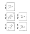
図2に、このプロセスが点の2つのV形組を使用した例を示す。基準データ組が実線で示されている。破線の第2データ組は、基準データ組を平行移動し回転移動して、組中の各点へ空間的雑音成分を追加することで得られた。図2bは、点の第1組から第2組への最初のマッピングを示す。正しい関連付けは実線で示されていて、正しくない関連付けは点線で示されている。図2cは、この最初のマッピング(3つの正しい関連付け及び4つの正しくない関連付けを含む)に基づいてアフィン変換を第2データ組へ適用した結果を示す。理解されるように、7つの割当て中、4つは正しくないが、変換された組はオリジナルにずっと接近している。図2dは、一致プロセスを繰返した結果を示す。最終結果が図2eに示されている(空間的雑音成分による差異は今明確である)。 FIG. 2 shows an example where this process uses two V-shaped sets of points. The reference data set is shown as a solid line. The dashed second data set was obtained by translating and rotating the reference data set and adding a spatial noise component to each point in the set. FIG. 2b shows the initial mapping from the first set of points to the second set. Correct associations are shown as solid lines, and incorrect associations are shown as dotted lines. FIG. 2c shows the result of applying an affine transformation to the second data set based on this initial mapping (including 3 correct associations and 4 incorrect associations). As can be seen, of the 7 assignments, 4 are incorrect, but the transformed set is much closer to the original. FIG. 2d shows the result of repeating the matching process. The final result is shown in FIG. 2e (the difference due to the spatial noise component is now clear).
上で概観したように、第1の推定フェーズの成功は第2のそれに依存していて、その逆も正しい。第1(マッピング)フェーズ中で不正確に一致されたいかなる点は、アルゴリズムの第2(パラメータ推定)フェーズ中の誤りを導く。しかし、経験により、十分な点が最初に正確に一致していれば、アルゴリズムは大変素早くロックを確立して、収束方向へ急速に加速されることが理解される。 As outlined above, the success of the first estimation phase depends on the second, and vice versa. Any point that is incorrectly matched during the first (mapping) phase leads to an error during the second (parameter estimation) phase of the algorithm. However, experience shows that if enough points are matched exactly at the beginning, the algorithm will establish a lock very quickly and accelerate rapidly in the direction of convergence.
実際には、1つのデータ組からのいくつかの点は他の組のいずれの点に必ずしも対応しない。これは、雑音の存在に起因するか、又は、光景中の真の違いに起因することもある(例えば、調査が実行された時とUUVミッションの時との間で海底のテクスチュが僅かに変化したか、又は、魚などのオブジェクトが光景中に入っている)。これは点対の平方距離分布に統計的な局外物の存在を生じ、変換パラメータの良好な推定を汚染する。1つの解決は、これらの統計的な局外物を、許容できないと見なされる平方距離値に関する上側閾値を置くことにより、排除することを試みることである。これは、統計的な局外物に対して、技術をより頑健なものとする。 In practice, some points from one data set do not necessarily correspond to any point in the other set. This may be due to the presence of noise, or may be due to true differences in the scene (for example, slight changes in seabed texture between when the survey was performed and during the UUV mission). Or an object such as a fish is in the scene). This results in the presence of statistical extraneous objects in the point pair square distance distribution, which pollutes a good estimate of the transformation parameters. One solution is to attempt to eliminate these statistical extraneous objects by placing an upper threshold on the square distance value that is considered unacceptable. This makes the technology more robust against statistical outliers.
基本的な閾値を計算する1つの方法は、平方距離分布の中央値の倍数を選ぶことにより決定される。中央値は、より頑健な統計値であるため、平均値よりも好んで選択される。代替的に、局外物に対してより洗練された技術を使用できる。 One way to calculate the basic threshold is determined by choosing a multiple of the median of the square distance distribution. The median value is preferred over the average value because it is a more robust statistic. Alternatively, more sophisticated techniques can be used for out-of-office items.
もし、誤り省略法が各点について利用可能であるならば、この情報が適合したデータ組間の差異を最小にするために使用される距離計量へ組み込むことができる。誤り計量はもはや単に点の両組間の平均平方距離ではなく、各点に関連した位置的不正確さ(x及びyの両方向での)を反映する。変位計量は、点と誤り省略法との間の両相対的位置の確率関数である。もし、位置誤りが全ての点についてx及びyの両方向において同じならば、誤り省略法は円に縮退して、前と同様に平均平方変位誤りを使用できる。すなわち、もし、可能ならば、個別の点のナビゲーションの不正確さを技術に組み込むことかできる。 If error skipping is available for each point, this information can be incorporated into the distance metric used to minimize the difference between matched data sets. The error metric no longer simply reflects the average square distance between both sets of points, but the positional inaccuracy (in both x and y directions) associated with each point. The displacement metric is a probability function of both relative positions between the point and the error skipping method. If the position error is the same in both x and y directions for all points, the error skipping method can be reduced to a circle and the mean square displacement error can be used as before. That is, if possible, individual point navigation inaccuracies can be incorporated into the technology.
試験において、収束が達成される点は2つのデータ組の点の密度に依存することが知られている。この最初のシミュレーションにおいては、収束は、それ以下では解決が発見されたと見なされる閾値最小限度レベルにより決定される。最適な閾値は、点密度、局外物のレベル等のパラメータに依存する。収束を識別するためのより頑健な方法は、適合の平均平方誤りが最小に安定する点を使用することである。 In testing, it is known that the point at which convergence is achieved depends on the density of the points in the two data sets. In this initial simulation, convergence is determined by the threshold minimum level below which a solution is deemed to have been found. The optimum threshold depends on parameters such as point density and level of extraneous objects. A more robust way to identify convergence is to use the point where the mean square error of the fit is minimally stable.
図3は、本発明の実施の形態によるナビゲーション・システムを概略的に示すもので、マップデータを記憶するためのデータ記憶10と移動体の外の環境を検出するための少なくとも1つのセンサー20とを含む。これらは、センサーにより検知されたデータを含む第1データ組をデータ記憶10に記憶されたマップデータである第2データ組へマップすることができるデータ組変換を計算する信号プロセッサ30に接続されている。そして、この変換データはナビゲーション制御40に供給されて、計算された変換に応答して移動体のナビゲーション制御を調節する。
FIG. 3 schematically shows a navigation system according to an embodiment of the invention, in which a
上述のアルゴリズムは、例えば、ナビゲーションを改良するために無人水中移動体のナビゲーション・システムに使用でき、第1データ組が領域のマップであり、第2データ組が無人水中移動体上のソナー検出器により検出された領域である。試験は、平らな領域では、水深測量ソナー検出器はFLS(前方監視ソナー)よりも良い結果を生ずることを示した。しかし、最良の結果は2つのタイプのソナーがタンデムに使用する時に得られた。 The algorithm described above can be used, for example, in an unmanned underwater vehicle navigation system to improve navigation, where the first data set is a map of the region and the second data set is a sonar detector on the unmanned underwater vehicle. This is the area detected by. Tests have shown that in flat areas, the depth survey sonar detector produces better results than FLS (forward monitoring sonar). However, the best results were obtained when two types of sonar were used in tandem.
代替的な実施の形態では、移動体の進行を描くことができるように、第1データ組は前のソナー・ピングからのデータを含む。他の実施の形態では、2つのシステムは、マップデータが利用可能な場所ではマップデータを使用できるようにし、そして利用可能でない場合は前のソナー・ピングからのデータが使用できるように、一緒にすることができる。 In an alternative embodiment, the first data set includes data from a previous sonar ping so that the progress of the mobile can be depicted. In other embodiments, the two systems can be used together so that map data can be used where map data is available, and data from previous sonar pings can be used if not available. can do.
マップデータが利用可能でない環境では、ソナーデータを前に記録された興味の有る領域のソナーマップと一致させることにより、移動体の位置を修正できる潜在能力がある。以下のパラグラフでは、海底のイメージに基づいて、以前にマップされていない領域内で、移動体の動きを6つの自由度の全てで計算するため、連続するデータ組間の変化を使用することを説明する。 In an environment where map data is not available, there is the potential to correct the position of the mobile by matching the sonar data to the sonar map of the area of interest previously recorded. In the following paragraphs, we will use the change between successive data sets to calculate the movement of a moving body in all six degrees of freedom in a previously unmapped region based on the image of the seabed. explain.
特に、光学カメラ技術を用いたビジュアルベース技術が特に効率的であることが知られている。しかし、濁りがカメラの視覚を制限する環境下では、従来の2D又は3Dソナーが使用できる。カメラを用いた技術は、水上の応用、例えば、車のための自動操縦、船のために海岸線を基準にすること、飛行機のために着陸滑走路を追尾すること、に特に効率的である。 In particular, it is known that visual base technology using optical camera technology is particularly efficient. However, in environments where turbidity restricts the camera's vision, conventional 2D or 3D sonar can be used. Camera-based techniques are particularly efficient for water applications such as autopilot for cars, shoreline reference for ships, tracking landing runways for airplanes.
この技術が動作するためには、1つのデータ組から別のデータ組へマップできる特徴の抽出に成功することが重要である。エッジ検出、ハック変換評価、テクチャベース特徴抽出、及び第2次導関数技術を含む、さまざまな特徴抽出技術が使用できる。 In order for this technique to work, it is important to succeed in extracting features that can be mapped from one data set to another. Various feature extraction techniques can be used, including edge detection, hack transform evaluation, texture-based feature extraction, and second derivative techniques.
一旦、特徴が識別されると、それらの動きがイメージ・フレーム間で追跡されなければならない。これは本発明の実施の形態の特徴マッピング方法を使用して行うことができる。 Once features are identified, their motion must be tracked between image frames. This can be done using the feature mapping method of the embodiment of the present invention.
本発明のさらなる実施の形態は、合成開口ソナー(SAS)に使用できる。SASの目的はソナーのプラットホームが移動する時に記録される一連のピングを一貫性を保ちながら統合することにより、高い解像度のイメージを形成することである。これが動作するさめには、音響波面の一貫性のある加算のために正確な統合経路が要求される。本発明の実施の形態の技術は、統合経路の正確性を改善するために、従来の前方監視ソナーデータと一緒に使用できる。この一貫性のある統合を実行するためには、合成開口長の全体にわたりソナー波長の小さな一部内でソナーの位置を知ることができなければならない。本発明の実施の形態の特徴マッピング技術はセンサーの位置検出を増強するために使用でき、よって、合成開口ソナーの精度を改良することができる。これは連続するピング間で相当な重複が存在する場合、例えば、同じ領域について典型的にいくつかの調査を与える側方監視ソナーを使用する場合、に動作する。重要な要件は、特徴が比較できるように、海底の同じ区画を複数回調査できることである。SASデータは、低いレベルで処理されて、そしてこの情報は高解像度イメージを生成するために使用され、これは対照的にカメラに基づく応用で実行されるのと同様に高レベルでイメージを融合する。 Further embodiments of the invention can be used for synthetic aperture sonar (SAS). The purpose of SAS is to create a high resolution image by coherently integrating a series of pings recorded as the sonar platform moves. For this to work, an accurate integration path is required for consistent addition of the acoustic wavefront. The techniques of the embodiments of the present invention can be used with conventional forward monitoring sonar data to improve the accuracy of the integrated path. In order to perform this consistent integration, it must be possible to know the position of the sonar within a small portion of the sonar wavelength throughout the synthetic aperture length. The feature mapping techniques of embodiments of the present invention can be used to enhance sensor position detection, thus improving the accuracy of synthetic aperture sonar. This works when there is considerable overlap between successive pings, for example when using a side monitoring sonar that typically gives several surveys on the same area. An important requirement is that the same section of the seabed can be surveyed multiple times so that features can be compared. SAS data is processed at a low level and this information is used to produce a high resolution image, which in contrast fuses the image at a high level as is done in camera-based applications. .
本発明の実施の形態は、監視システム中を通過する対象を追跡するために使用される特徴追跡アルゴリズムに使用できる。本発明の別の実施の形態は、移動体に搭載されたカメラなど、移動するセンサーにより生成されるイメージからマップデータを生成するために使用できる。それは、例えば、コンベヤベルト上で移動する対象の工業的検査などの検査及び品質管理のためにも使用できる。この技術は、一旦、異常が検出されると、対象を追跡するために使用できる。また、前述したマッピングの説明は地理的又は他の物理的なデータのマッピングに限定する意図は無いことが理解できる。この用語は、数学的意味、すなわち、与えられた組の各要素が第2組の1つの要素に関連付けられている一致、を含むことを意図している。また、異なるタイプ又はプロセス又はスキーム内の異なるレベルでの関連する要素間のより一般的な意味の程度の対応を含むことを意図している。同様に、前述の特徴の用語の説明は、地形学的又は物理的特徴に限定する意図はない。従って、視覚的及び/又は音声データ組内に表されるものを含む抽象的な特徴も含むことを意図している。 Embodiments of the present invention can be used in feature tracking algorithms that are used to track objects passing through a surveillance system. Another embodiment of the present invention can be used to generate map data from an image generated by a moving sensor, such as a camera mounted on a moving object. It can also be used for inspection and quality control, for example industrial inspection of objects moving on a conveyor belt. This technique can be used to track an object once an abnormality is detected. It can also be appreciated that the above description of mapping is not intended to be limited to mapping of geographic or other physical data. The term is intended to include the mathematical meaning, that is, a match in which each element of a given set is associated with one element of a second set. It is also intended to include a more general sense of correspondence between related elements at different levels within different types or processes or schemes. Similarly, the description of terminology of the aforementioned features is not intended to be limited to topographical or physical features. Thus, it is intended to include abstract features including those represented in visual and / or audio data sets.
本発明の特定の実施の形態について説明したが、本発明はそれに限定する意図はなく、多くの修正や追加が本発明の範囲内で行うことができることは明らかである。例えば、本発明の範囲から逸脱することなく、独立の請求項の特徴のさまざまな組合わせを従属する請求項の特徴と共に行うことができる。 While specific embodiments of the invention have been described, it will be appreciated that the invention is not intended to be limited thereto and that many modifications and additions can be made within the scope of the invention. For example, various combinations of the features of the independent claims can be made with the features of the dependent claims without departing from the scope of the invention.
Claims (36)
(a)前記第1データ組中の前記少なくとも1つの特徴に関する点の第1組を抽出するステップと、
(b)点の前記第1組を前記第2データ組中の点の第2組と関連付けするステップと、
(c)前記第1データ組からの点の前記第1組を前記第2データ組中の点の前記第2組へ少なくとも近似的にマップするために前記特徴追跡変換を計算するステップとを含み、前記特徴追跡変換を計算する前記ステップが、
(i)個別の点のマッピング推定を生成するために、点の前記2つの組の内の1つの組の各点に対して、点の前記他の組の選択された点への前記点のマッピングを推定するステップと、
(ii)点の前記1つの組を点の前記他の組へマップするための推定変換を生成するために前記個別の点のマッピングの推定を組合わせるステップと、
(iii)近似イメージ位置を生成するために前記推定変換を点の前記1つの組へ適用するステップと、
(iv)点の前記他の組を前記近似イメージ位置からの点の組へマッピングするための推定変換を生成するために前記(i)乃至(iii)ステップを反復繰返すステップと、
(v)点の前記第1組を点の前記第2組へマッピングするために前記推定変換の組合せから前記特徴追跡変換を導出するステップとを含む方法。 A method of deriving a feature tracking transform for mapping at least one feature from a first data set onto a corresponding feature from a second data set, comprising:
(A) extracting a first set of points relating to the at least one feature in the first data set;
(B) associating the first set of points with a second set of points in the second data set;
(C) calculating the feature tracking transform to at least approximately map the first set of points from the first data set to the second set of points in the second data set. The step of calculating the feature tracking transform comprises:
(I) for each point of a set of the two sets of points, for each point of the set of points to a selected point of the other set of points to generate a mapping estimate of the individual points Estimating a mapping;
(Ii) combining an estimate of the mapping of the individual points to generate an estimated transform for mapping the one set of points to the other set of points;
(Iii) applying the estimated transform to the one set of points to generate approximate image positions;
(Iv) iteratively repeating steps (i) through (iii) to generate a presumed transformation for mapping the other set of points to a set of points from the approximate image location;
(V) deriving the feature tracking transform from a combination of the estimated transforms to map the first set of points to the second set of points.
前記推定変形の組合わせから前記特徴追跡変形を導出するステップと、
をさらに含む請求項1に記載の方法。 Steps (i) through (iii) are used until the approximate image position is aligned with the second set of points within predetermined limits using the latest approximate image position and alternately the first and second sets of points. Repeating iteratively, and deriving the feature tracking deformation from the combination of the estimated deformations;
The method of claim 1 further comprising:
前記特徴追跡変換を前記第1データ組を前記第2データ組上にマップするためのデータ組変換として出力するステップをさらに含む方法。 A method for deriving a data set transformation for mapping a first data set onto a second data set, comprising the method of any of claims 1 to 16,
The method further includes outputting the feature tracking transform as a data set transform for mapping the first data set onto the second data set.
前記ベクトル又は点の少なくとも1つのさらなる組を第2データ組中のベクトル又は点の第2のさらなる組へ関連付けし、
請求項1のステップ(i)乃至(v)を用いて、前記第1データ組からの前記ベクトル又は点の少なくとも1つのさらなる組を前記第2データ組からのベクトル又は点の第2のさらなる組へ少なくとも近似的にマップするために少なくとも1つのさらなる特徴追跡変換を計算し、
データ組変換を生成するために前記少なくとも1つの特徴追跡変換及び前記さらなる特徴追跡変換を組合わせ、そして
前記データ組変換を出力する、
ことを含む請求項17に記載のデータ組変換を抽出する方法。 Further comprising extracting at least one further set of vectors or points associated with at least one feature from said first data set;
Associating at least one further set of vectors or points with a second further set of vectors or points in a second data set;
Using steps (i) to (v) of claim 1, at least one further set of vectors or points from the first data set is converted to a second further set of vectors or points from the second data set. Calculating at least one additional feature tracking transform to map at least approximately to
Combining the at least one feature tracking transformation and the further feature tracking transformation to generate a data set transformation, and outputting the data set transformation;
The method of extracting a data set conversion according to claim 17 comprising:
請求項17乃至19のいずれかに記載の第1データ組を第2データ組上へマッピングするためのデータ組変換を導出する方法を含み、前記第1データ組は前記センサーにより検知された前記領域の最初のイメージを含み、前記第2データ組は前記センサーがある距離を移動した後に前記センサーにより検知された前記領域のその後のイメージを含み、
イメージ間で前記領域に対して前記センサーが相対的に移動した前記距離を推定するために前記データ組変換を使用し、
前記推定された距離を用いて前記イメージを組合わせ、そして
前記組合わせられたイメージから前記領域のマップを生成するためにその後のイメージについて前記ステップを繰返す
ことを含むイメージ処理方法。 20. An image processing method for generating a map of the region from a plurality of the images of the region generated by a sensor that detects an image while relatively moving the region. A method of deriving a data set transformation for mapping the first data set onto the second data set, wherein the first data set includes a first image of the region detected by the sensor, and The data set includes subsequent images of the area detected by the sensor after the sensor has moved a distance,
Using the data set transformation to estimate the distance that the sensor has moved relative to the region between images;
Combining the images using the estimated distance and repeating the steps on subsequent images to generate a map of the region from the combined images.
請求項1乃至16のいずれかに記載の第1データ組からの少なくとも1つの特徴を第2データ組からの対応する特徴へマップするための特徴追跡変換を導出する方法を含み、前記第1データ組は前記センサーにより検知されたイメージを含み、前記第2データ組は前記センサーによりその後に検知されたイメージを含み、前記特徴追跡変換から前記特徴が移動した方向及び距離を導出することを含む特徴追跡方法。 A feature tracking method for tracking a feature when the feature moves relative to a sensor,
17. A method for deriving a feature tracking transform for mapping at least one feature from a first data set to a corresponding feature from a second data set according to any of the preceding claims, wherein the first data The set includes images detected by the sensor, the second data set includes images subsequently detected by the sensor, and includes deriving the direction and distance the feature has moved from the feature tracking transform. Tracking method.
前記第1データ組から少なくとも1つの特徴に関連する点の第1組を抽出しそして点の前記第1組を第2データ組内の点の第2組に一致させることができる信号プロセッサと、
前記第1データ組からの点の前記第1組を前記第2データ組内の点の前記第2組へ少なくとも近似的にマップするための特徴追跡変換を計算できる計算回路とを含み、前記計算回路は以下のステップを実行でき、
点の前記第1組又は前記第2組の1つの組の各点について、前記点を点の前記第1組又は前記第2組の他の組内の点へのマッピングを推定するステップ、
点の前記1つの組を点の前記他の組へマップするための推定変換を生成するために前記個別の点のマッピング推定を組合わせるステップ、
近似イメージ位置を生成するために前記推定変換を点の前記1つの組に適用するステップと、
点の前記他の組を前記近似イメージ位置から点の組へマッピングするための推定変換を生成するため前記ステップを反復繰返して実行するステップ、そして
前記推定変換の組合わせから点の前記第1組を点の前記第2組へマッピングするための前記特徴追跡変換を導出するステップ、
前記装置は、さらに前記特徴追跡変換を出力するための出力装置を含む装置。 An apparatus for deriving a feature tracking transform for mapping at least one feature from a first data set to a corresponding feature from a second data set,
A signal processor capable of extracting a first set of points associated with at least one feature from the first data set and matching the first set of points to a second set of points in a second data set;
A computing circuit capable of computing a feature tracking transform for mapping at least approximately the first set of points from the first data set to the second set of points in the second data set, The circuit can perform the following steps:
For each point of the first set of points or one set of the second set, estimating the mapping of the points to points in the other set of the first set or the second set of points;
Combining the individual point mapping estimates to generate an estimated transform for mapping the one set of points to the other set of points;
Applying the estimated transformation to the one set of points to generate approximate image positions;
Repeatedly performing the steps to generate an estimated transform for mapping the other set of points from the approximate image location to the set of points; and from the combination of estimated transforms, the first set of points Deriving the feature tracking transform for mapping to the second set of points;
The apparatus further includes an output device for outputting the feature tracking transform.
マップデータを格納することができる記憶手段と、
前記移動体の外側の前記環境を検出するための少なくとも1つのセンサーと、
請求項28に記載のコンピュータ・プログラム製品を含み、前記記憶手段に格納されている前記マップデータを含む第1データ組を前記少なくとも1つのセンサーにより検出されたイメージデータを含む第2データ組へマップすることができるデータ組変換を計算できる信号プロセッサと、
前記移動体のナビゲーションを制御できるナビゲーション制御手段とを含み、
前記ナビゲーション制御手段は前記計算されたデータ組変換に応答することができるナビゲーション・システム。 A navigation system for enhancing the navigation capability of a mobile object,
Storage means capable of storing map data;
At least one sensor for detecting the environment outside the moving body;
29. A computer program product according to claim 28, wherein a first data set comprising said map data stored in said storage means is mapped to a second data set comprising image data detected by said at least one sensor. A signal processor capable of calculating a data set transformation that can be
Navigation control means capable of controlling navigation of the mobile body,
A navigation system in which the navigation control means can respond to the calculated data set conversion.
マップデータを記憶することができる記憶手段と、
前記移動体の外側の前記環境を検出するための少なくとも1つのセンサーと、
請求項28に記載のコンピュータ・プログラム製品を含み、記憶されているマップデータ及びマップデータが利用できない場合は前記センサーにより前に検出されたデータの両方を含む第1データ組を前記少なくとも1つのセンサーにより現在検出されたイメージデータを含む第2データ組へマップすることができるデータ組変換を計算できる信号プロセッサと、
前記移動体のナビゲーションを制御できるナビゲーション制御手段とを含み、
前記ナビゲーション制御手段は前記計算されたデータ組変換に応答することができるナビゲーション・システム。 A navigation system for enhancing the navigation capability of a mobile object,
Storage means capable of storing map data;
At least one sensor for detecting the environment outside the moving body;
29. A computer program product according to claim 28, wherein the at least one sensor comprises a first data set comprising both stored map data and data previously detected by the sensor if map data is not available. A signal processor capable of calculating a data set transformation that can be mapped to a second data set containing image data currently detected by
Navigation control means capable of controlling navigation of the mobile body,
A navigation system in which the navigation control means can respond to the calculated data set conversion.
マップデータを記憶することができる記憶手段と、
前記移動体の前側の領域及び前記移動体の下側の領域を含む前記移動体の外側の前記環境を検出するための複数のセンサーと、
請求項28に記載のコンピュータ・プログラム製品を含み、前記移動体の前方の領域を監視する前記センサーにより検出されたデータを含む第1データ組を前記移動体の下側の領域を監視する前記センサーにより検出されたデータを含む第2データ組へマップすることができるデータ組変換を計算できる信号プロセッサと、
前記移動体のナビゲーションを制御できるナビゲーション制御手段とを含み、
前記ナビゲーション制御手段は前記計算されたデータ組変換に応答することができるナビゲーション・システム。 A navigation system for enhancing the navigation capability of a mobile object,
Storage means capable of storing map data;
A plurality of sensors for detecting the environment outside the moving body, including an area on the front side of the moving body and a lower area on the moving body;
29. The sensor comprising the computer program product according to claim 28, wherein the sensor monitors a lower area of the moving body with a first data set including data detected by the sensor monitoring an area in front of the moving body. A signal processor capable of calculating a data set transformation that can be mapped to a second data set containing the data detected by
Navigation control means capable of controlling navigation of the mobile body,
A navigation system in which the navigation control means can respond to the calculated data set conversion.
Applications Claiming Priority (2)
| Application Number | Priority Date | Filing Date | Title |
|---|---|---|---|
| GBGB0212748.8A GB0212748D0 (en) | 2002-05-31 | 2002-05-31 | Feature mapping between data sets |
| PCT/GB2003/002329 WO2003102870A2 (en) | 2002-05-31 | 2003-05-28 | Feature mapping between data sets |
Publications (2)
| Publication Number | Publication Date |
|---|---|
| JP2005528707A true JP2005528707A (en) | 2005-09-22 |
| JP2005528707A5 JP2005528707A5 (en) | 2009-12-03 |
Family
ID=9937900
Family Applications (1)
| Application Number | Title | Priority Date | Filing Date |
|---|---|---|---|
| JP2004509881A Pending JP2005528707A (en) | 2002-05-31 | 2003-05-28 | Feature mapping between data sets |
Country Status (6)
| Country | Link |
|---|---|
| US (1) | US7124022B2 (en) |
| EP (1) | EP1516286A2 (en) |
| JP (1) | JP2005528707A (en) |
| AU (1) | AU2003241021A1 (en) |
| GB (1) | GB0212748D0 (en) |
| WO (1) | WO2003102870A2 (en) |
Families Citing this family (33)
| Publication number | Priority date | Publication date | Assignee | Title |
|---|---|---|---|---|
| US7315259B2 (en) * | 2005-08-11 | 2008-01-01 | Google Inc. | Techniques for displaying and caching tiled map data on constrained-resource services |
| US7933897B2 (en) | 2005-10-12 | 2011-04-26 | Google Inc. | Entity display priority in a distributed geographic information system |
| WO2008022313A2 (en) * | 2006-08-18 | 2008-02-21 | Raytheon Company | Method and system for determining task scheduling probability |
| US8220408B2 (en) * | 2007-07-31 | 2012-07-17 | Stone William C | Underwater vehicle with sonar array |
| US8082100B2 (en) | 2007-10-19 | 2011-12-20 | Grace Ted V | Watercraft automation and aquatic effort data utilization |
| JP2009163504A (en) * | 2008-01-07 | 2009-07-23 | Panasonic Corp | Image deformation method and the like |
| US20090216410A1 (en) * | 2008-02-26 | 2009-08-27 | William Edward Allen | Automated machine management system with destination selection |
| US8233664B2 (en) * | 2008-11-12 | 2012-07-31 | Eastman Kodak Company | Determining relative depth of points in multiple videos |
| WO2010095946A1 (en) * | 2009-02-20 | 2010-08-26 | Nederlandse Organisatie Voor Toegepast-Natuurwetenschappelijk Onderzoek Tno | A method of detecting a scatterer in a structure, a radar system and a computer program product |
| US8463458B2 (en) * | 2009-09-03 | 2013-06-11 | Johnson Outdoors Marine Electronics, Inc. | Depth highlight, depth highlight range, and water level offset highlight display and systems |
| US8442709B2 (en) * | 2009-12-11 | 2013-05-14 | Lockheed Martin Corporation | Underwater investigation system providing unmanned underwater vehicle (UUV) guidance based upon updated position state estimates and related methods |
| JP2011198330A (en) * | 2010-03-24 | 2011-10-06 | National Institute Of Advanced Industrial Science & Technology | Method and program for collation in three-dimensional registration |
| US8761976B2 (en) | 2010-07-16 | 2014-06-24 | Johnson Outdoors Inc. | System and method for controlling a trolling motor |
| US8629788B1 (en) * | 2010-08-10 | 2014-01-14 | Rockwell Collins, Inc. | Sensing, display, and dissemination of detected turbulence |
| US8645012B2 (en) | 2010-08-20 | 2014-02-04 | Johnson Outdoors Inc. | System and method for automatically navigating a depth contour |
| US8543269B1 (en) * | 2010-08-20 | 2013-09-24 | Johnson Outdoors Marine Electronics, Inc. | Digital mapping display functions for a GPS/sonar unit |
| CN101957992B (en) * | 2010-09-30 | 2012-05-02 | 清华大学 | Data characteristic extracting and matching method for two-dimensional injective mapping curved surface |
| US8442716B2 (en) * | 2010-10-31 | 2013-05-14 | Microsoft Corporation | Identifying physical locations of entities |
| US11480965B2 (en) | 2010-11-19 | 2022-10-25 | Maid Ip Holdings Pty/Ltd | Automatic location placement system |
| US9778657B2 (en) | 2010-11-19 | 2017-10-03 | Bradley Tyers | Automatic location placement system |
| SE535920C2 (en) * | 2011-02-10 | 2013-02-19 | Hans Frimmel | Imaging method based on level-set function |
| US9104697B2 (en) * | 2012-07-24 | 2015-08-11 | Navico Holdings As | Aquatic geographic information system |
| US9147226B2 (en) * | 2012-09-10 | 2015-09-29 | Nokia Technologies Oy | Method, apparatus and computer program product for processing of images |
| WO2017008246A1 (en) * | 2015-07-14 | 2017-01-19 | SZ DJI Technology Co., Ltd. | Method, apparatus, and system for determining a movement of a mobile platform |
| US10365366B2 (en) | 2016-06-21 | 2019-07-30 | Navico Holding As | Adjustable range viewing of sonar imagery during trip replay |
| US9986197B2 (en) | 2016-08-24 | 2018-05-29 | Navico Holding As | Trip replay experience |
| DE102016116471A1 (en) | 2016-09-02 | 2018-03-08 | Atlas Elektronik Gmbh | Navigation correction module and unmanned underwater vehicle with it and procedures |
| US10304342B2 (en) * | 2016-11-08 | 2019-05-28 | Ge Aviation Systems Llc | Ground-based data acquisition system |
| US11035933B2 (en) | 2018-05-04 | 2021-06-15 | Honda Motor Co., Ltd. | Transition map between lidar and high-definition map |
| US11061132B2 (en) * | 2018-05-21 | 2021-07-13 | Johnson Controls Technology Company | Building radar-camera surveillance system |
| JP7051625B2 (en) * | 2018-07-12 | 2022-04-11 | 古野電気株式会社 | Underwater detector and underwater detection method |
| EP3702802A1 (en) * | 2019-03-01 | 2020-09-02 | Aptiv Technologies Limited | Method of multi-sensor data fusion |
| AU2020289853B2 (en) * | 2020-04-09 | 2022-02-03 | Sensetime International Pte. Ltd. | Matching method and apparatus, electronic device, computer-readable storage medium, and computer program |
Family Cites Families (9)
| Publication number | Priority date | Publication date | Assignee | Title |
|---|---|---|---|---|
| EP0200284B1 (en) * | 1980-04-11 | 1993-09-29 | Ampex Corporation | Interpolation filter for image transformation system |
| JPS6084610A (en) | 1983-10-17 | 1985-05-14 | Hitachi Ltd | Guiding device |
| GB8706348D0 (en) * | 1987-03-17 | 1987-04-23 | Quantel Ltd | Electronic image processing systems |
| US4891762A (en) | 1988-02-09 | 1990-01-02 | Chotiros Nicholas P | Method and apparatus for tracking, mapping and recognition of spatial patterns |
| DE3915631A1 (en) | 1989-05-12 | 1990-11-15 | Dornier Luftfahrt | NAVIGATION PROCEDURE |
| US5303795A (en) * | 1991-01-24 | 1994-04-19 | Buell Motor Company, Inc. | Motorcycle luggage carrier |
| US5592599A (en) * | 1991-12-18 | 1997-01-07 | Ampex Corporation | Video special effects system with graphical operator interface |
| GB9813760D0 (en) | 1998-06-25 | 1998-08-26 | Geco Prakla Uk Ltd | Seismic data signal processing method |
| IL135560A0 (en) | 2000-04-09 | 2001-05-20 | Dream Team Ltd | Method for processing an image |
-
2002
- 2002-05-31 GB GBGB0212748.8A patent/GB0212748D0/en not_active Ceased
-
2003
- 2003-05-28 JP JP2004509881A patent/JP2005528707A/en active Pending
- 2003-05-28 AU AU2003241021A patent/AU2003241021A1/en not_active Abandoned
- 2003-05-28 EP EP03730339A patent/EP1516286A2/en not_active Withdrawn
- 2003-05-28 US US10/516,263 patent/US7124022B2/en not_active Expired - Fee Related
- 2003-05-28 WO PCT/GB2003/002329 patent/WO2003102870A2/en active Application Filing
Also Published As
| Publication number | Publication date |
|---|---|
| GB0212748D0 (en) | 2002-07-10 |
| EP1516286A2 (en) | 2005-03-23 |
| AU2003241021A1 (en) | 2003-12-19 |
| WO2003102870A2 (en) | 2003-12-11 |
| US7124022B2 (en) | 2006-10-17 |
| WO2003102870A3 (en) | 2004-07-01 |
| US20060123050A1 (en) | 2006-06-08 |
| AU2003241021A8 (en) | 2003-12-19 |
Similar Documents
| Publication | Publication Date | Title |
|---|---|---|
| US7124022B2 (en) | Feature mapping between data sets | |
| Palomer et al. | Inspection of an underwater structure using point‐cloud SLAM with an AUV and a laser scanner | |
| US20230130320A1 (en) | Laser scanner with real-time, online ego-motion estimation | |
| US10096129B2 (en) | Three-dimensional mapping of an environment | |
| Muhovič et al. | Obstacle tracking for unmanned surface vessels using 3-D point cloud | |
| US10275649B2 (en) | Apparatus of recognizing position of mobile robot using direct tracking and method thereof | |
| US10307910B2 (en) | Apparatus of recognizing position of mobile robot using search based correlative matching and method thereof | |
| US20170151675A1 (en) | Apparatus for recognizing position of mobile robot using edge based refinement and method thereof | |
| EP3526626A1 (en) | Laser scanner with real-time, online ego-motion estimation | |
| Nair et al. | Moving obstacle detection from a navigating robot | |
| JP6782903B2 (en) | Self-motion estimation system, control method and program of self-motion estimation system | |
| KR102064257B1 (en) | Underwater navigation method and system for underwater vehicle | |
| Clement et al. | Robust monocular visual teach and repeat aided by local ground planarity and color‐constant imagery | |
| Elibol et al. | Augmented state–extended Kalman filter combined framework for topology estimation in large‐area underwater mapping | |
| Hurtós et al. | Real-time mosaicing with two-dimensional forward-looking sonar | |
| Wang et al. | Real-time dense 3d mapping of underwater environments | |
| Birk et al. | Simultaneous localization and mapping (SLAM) | |
| Ruscio et al. | Visual-based navigation strategy for autonomous underwater vehicles in monitoring scenarios | |
| McConnell et al. | Perception for Underwater Robots | |
| Amarasinghe et al. | Monocular visual slam for underwater navigation in turbid and dynamic environments | |
| Sekkati et al. | 3-D motion estimation for positioning from 2-D acoustic video imagery | |
| Gracias | Mosaic-based visual navigation for autonomous underwater vehicles | |
| Elibol et al. | Online underwater optical mapping for trajectories with gaps | |
| Vandrish et al. | Towards auv route following using qualitative navigation | |
| Kleiner et al. | Mapping for the support of first responders in critical domains |
Legal Events
| Date | Code | Title | Description |
|---|---|---|---|
| A521 | Written amendment |
Free format text: JAPANESE INTERMEDIATE CODE: A523 Effective date: 20060111 |
|
| A621 | Written request for application examination |
Free format text: JAPANESE INTERMEDIATE CODE: A621 Effective date: 20060111 |
|
| A131 | Notification of reasons for refusal |
Free format text: JAPANESE INTERMEDIATE CODE: A131 Effective date: 20090413 |
|
| A601 | Written request for extension of time |
Free format text: JAPANESE INTERMEDIATE CODE: A601 Effective date: 20090713 |
|
| A602 | Written permission of extension of time |
Free format text: JAPANESE INTERMEDIATE CODE: A602 Effective date: 20090721 |
|
| A521 | Written amendment |
Free format text: JAPANESE INTERMEDIATE CODE: A523 Effective date: 20091007 |
|
| A524 | Written submission of copy of amendment under section 19 (pct) |
Free format text: JAPANESE INTERMEDIATE CODE: A524 Effective date: 20091007 |
|
| A02 | Decision of refusal |
Free format text: JAPANESE INTERMEDIATE CODE: A02 Effective date: 20091116 |