JP2005521463A - Surgical Suture Instruments and Methods of Use References to pending applications This application is (1) published on 28 January 2003 by Frederic P. Field et al. And pending US patent application Ser. No. 10 / 352,600 (Attorney Docket No. ONUX-22CON), and (2) Gregory E. Sankov on March 4, 2003. (Gregory E. Sancoff) et al. “Pending US patent application Ser. No. 10 / 378,805, filed under the name“ SURGICALS TURRINGINSTRUMENTANDMETHODFUSE ”. (Attorney Docket No. ONUX-15CON), which is a co-pending application, which was also published on March 25, 2002 by Frederic P. Field et al. Claims the benefit of pending US Provisional Patent Application No. 60 / 367,395 (Attorney Docket No. ONUX-31PROV), filed as "SURGICALSUTURINGINSTRUMENTANDMETHODFOFUSE". This patent application also claims the benefit of. The three above-identified patent applications are hereby incorporated by reference in their entirety. - Google Patents
Surgical Suture Instruments and Methods of Use References to pending applications This application is (1) published on 28 January 2003 by Frederic P. Field et al. And pending US patent application Ser. No. 10 / 352,600 (Attorney Docket No. ONUX-22CON), and (2) Gregory E. Sankov on March 4, 2003. (Gregory E. Sancoff) et al. “Pending US patent application Ser. No. 10 / 378,805, filed under the name“ SURGICALS TURRINGINSTRUMENTANDMETHODFUSE ”. (Attorney Docket No. ONUX-15CON), which is a co-pending application, which was also published on March 25, 2002 by Frederic P. Field et al. Claims the benefit of pending US Provisional Patent Application No. 60 / 367,395 (Attorney Docket No. ONUX-31PROV), filed as "SURGICALSUTURINGINSTRUMENTANDMETHODFOFUSE". This patent application also claims the benefit of. The three above-identified patent applications are hereby incorporated by reference in their entirety. Download PDFInfo
- Publication number
- JP2005521463A JP2005521463A JP2003579672A JP2003579672A JP2005521463A JP 2005521463 A JP2005521463 A JP 2005521463A JP 2003579672 A JP2003579672 A JP 2003579672A JP 2003579672 A JP2003579672 A JP 2003579672A JP 2005521463 A JP2005521463 A JP 2005521463A
- Authority
- JP
- Japan
- Prior art keywords
- wire
- suture wire
- suture
- channel
- suturing
- Prior art date
- Legal status (The legal status is an assumption and is not a legal conclusion. Google has not performed a legal analysis and makes no representation as to the accuracy of the status listed.)
- Pending
Links
Images


Classifications
-
- A—HUMAN NECESSITIES
- A61—MEDICAL OR VETERINARY SCIENCE; HYGIENE
- A61B—DIAGNOSIS; SURGERY; IDENTIFICATION
- A61B17/00—Surgical instruments, devices or methods, e.g. tourniquets
- A61B17/064—Surgical staples, i.e. penetrating the tissue
-
- A—HUMAN NECESSITIES
- A61—MEDICAL OR VETERINARY SCIENCE; HYGIENE
- A61B—DIAGNOSIS; SURGERY; IDENTIFICATION
- A61B17/00—Surgical instruments, devices or methods, e.g. tourniquets
- A61B17/04—Surgical instruments, devices or methods, e.g. tourniquets for suturing wounds; Holders or packages for needles or suture materials
- A61B17/0469—Suturing instruments for use in minimally invasive surgery, e.g. endoscopic surgery
-
- A—HUMAN NECESSITIES
- A61—MEDICAL OR VETERINARY SCIENCE; HYGIENE
- A61B—DIAGNOSIS; SURGERY; IDENTIFICATION
- A61B17/00—Surgical instruments, devices or methods, e.g. tourniquets
- A61B17/064—Surgical staples, i.e. penetrating the tissue
- A61B17/0644—Surgical staples, i.e. penetrating the tissue penetrating the tissue, deformable to closed position
-
- A—HUMAN NECESSITIES
- A61—MEDICAL OR VETERINARY SCIENCE; HYGIENE
- A61B—DIAGNOSIS; SURGERY; IDENTIFICATION
- A61B17/00—Surgical instruments, devices or methods, e.g. tourniquets
- A61B17/068—Surgical staplers, e.g. containing multiple staples or clamps
-
- A—HUMAN NECESSITIES
- A61—MEDICAL OR VETERINARY SCIENCE; HYGIENE
- A61B—DIAGNOSIS; SURGERY; IDENTIFICATION
- A61B17/00—Surgical instruments, devices or methods, e.g. tourniquets
- A61B17/28—Surgical forceps
- A61B17/29—Forceps for use in minimally invasive surgery
- A61B17/2909—Handles
-
- A—HUMAN NECESSITIES
- A61—MEDICAL OR VETERINARY SCIENCE; HYGIENE
- A61B—DIAGNOSIS; SURGERY; IDENTIFICATION
- A61B17/00—Surgical instruments, devices or methods, e.g. tourniquets
- A61B2017/00743—Type of operation; Specification of treatment sites
- A61B2017/00778—Operations on blood vessels
- A61B2017/00783—Valvuloplasty
-
- A—HUMAN NECESSITIES
- A61—MEDICAL OR VETERINARY SCIENCE; HYGIENE
- A61B—DIAGNOSIS; SURGERY; IDENTIFICATION
- A61B17/00—Surgical instruments, devices or methods, e.g. tourniquets
- A61B17/04—Surgical instruments, devices or methods, e.g. tourniquets for suturing wounds; Holders or packages for needles or suture materials
- A61B2017/0498—Surgical instruments, devices or methods, e.g. tourniquets for suturing wounds; Holders or packages for needles or suture materials for advancing a suture filament along a helical path through tissue
-
- A—HUMAN NECESSITIES
- A61—MEDICAL OR VETERINARY SCIENCE; HYGIENE
- A61B—DIAGNOSIS; SURGERY; IDENTIFICATION
- A61B17/00—Surgical instruments, devices or methods, e.g. tourniquets
- A61B17/04—Surgical instruments, devices or methods, e.g. tourniquets for suturing wounds; Holders or packages for needles or suture materials
- A61B17/06—Needles ; Sutures; Needle-suture combinations; Holders or packages for needles or suture materials
- A61B17/06166—Sutures
- A61B2017/06171—Sutures helically or spirally coiled
-
- A—HUMAN NECESSITIES
- A61—MEDICAL OR VETERINARY SCIENCE; HYGIENE
- A61B—DIAGNOSIS; SURGERY; IDENTIFICATION
- A61B17/00—Surgical instruments, devices or methods, e.g. tourniquets
- A61B17/064—Surgical staples, i.e. penetrating the tissue
- A61B2017/0649—Coils or spirals
-
- A—HUMAN NECESSITIES
- A61—MEDICAL OR VETERINARY SCIENCE; HYGIENE
- A61F—FILTERS IMPLANTABLE INTO BLOOD VESSELS; PROSTHESES; DEVICES PROVIDING PATENCY TO, OR PREVENTING COLLAPSING OF, TUBULAR STRUCTURES OF THE BODY, e.g. STENTS; ORTHOPAEDIC, NURSING OR CONTRACEPTIVE DEVICES; FOMENTATION; TREATMENT OR PROTECTION OF EYES OR EARS; BANDAGES, DRESSINGS OR ABSORBENT PADS; FIRST-AID KITS
- A61F2/00—Filters implantable into blood vessels; Prostheses, i.e. artificial substitutes or replacements for parts of the body; Appliances for connecting them with the body; Devices providing patency to, or preventing collapsing of, tubular structures of the body, e.g. stents
- A61F2/0063—Implantable repair or support meshes, e.g. hernia meshes
-
- A—HUMAN NECESSITIES
- A61—MEDICAL OR VETERINARY SCIENCE; HYGIENE
- A61F—FILTERS IMPLANTABLE INTO BLOOD VESSELS; PROSTHESES; DEVICES PROVIDING PATENCY TO, OR PREVENTING COLLAPSING OF, TUBULAR STRUCTURES OF THE BODY, e.g. STENTS; ORTHOPAEDIC, NURSING OR CONTRACEPTIVE DEVICES; FOMENTATION; TREATMENT OR PROTECTION OF EYES OR EARS; BANDAGES, DRESSINGS OR ABSORBENT PADS; FIRST-AID KITS
- A61F2/00—Filters implantable into blood vessels; Prostheses, i.e. artificial substitutes or replacements for parts of the body; Appliances for connecting them with the body; Devices providing patency to, or preventing collapsing of, tubular structures of the body, e.g. stents
- A61F2/02—Prostheses implantable into the body
- A61F2/30—Joints
- A61F2002/30001—Additional features of subject-matter classified in A61F2/28, A61F2/30 and subgroups thereof
- A61F2002/30003—Material related properties of the prosthesis or of a coating on the prosthesis
- A61F2002/3006—Properties of materials and coating materials
- A61F2002/30107—Properties of materials and coating materials using materials or accessories for preventing galvanic or electrolytic corrosion
-
- A—HUMAN NECESSITIES
- A61—MEDICAL OR VETERINARY SCIENCE; HYGIENE
- A61F—FILTERS IMPLANTABLE INTO BLOOD VESSELS; PROSTHESES; DEVICES PROVIDING PATENCY TO, OR PREVENTING COLLAPSING OF, TUBULAR STRUCTURES OF THE BODY, e.g. STENTS; ORTHOPAEDIC, NURSING OR CONTRACEPTIVE DEVICES; FOMENTATION; TREATMENT OR PROTECTION OF EYES OR EARS; BANDAGES, DRESSINGS OR ABSORBENT PADS; FIRST-AID KITS
- A61F2210/00—Particular material properties of prostheses classified in groups A61F2/00 - A61F2/26 or A61F2/82 or A61F9/00 or A61F11/00 or subgroups thereof
- A61F2210/0009—Particular material properties of prostheses classified in groups A61F2/00 - A61F2/26 or A61F2/82 or A61F9/00 or A61F11/00 or subgroups thereof using materials or accessories for preventing galvanic or electrolytic corrosion
Landscapes
- Health & Medical Sciences (AREA)
- Life Sciences & Earth Sciences (AREA)
- Surgery (AREA)
- Heart & Thoracic Surgery (AREA)
- Engineering & Computer Science (AREA)
- Biomedical Technology (AREA)
- Nuclear Medicine, Radiotherapy & Molecular Imaging (AREA)
- Medical Informatics (AREA)
- Molecular Biology (AREA)
- Animal Behavior & Ethology (AREA)
- General Health & Medical Sciences (AREA)
- Public Health (AREA)
- Veterinary Medicine (AREA)
- Surgical Instruments (AREA)
Abstract
対象の少なくとも2つの部分に可撓性の細長い要素を導入する装置(2)を開示している。好ましい実施形態では、装置は、近位端および遠位端と、可撓性の細長い要素を、その近位端が対象を貫通するのに十分な力で装置(2)の遠位端から出ることができるように、装置(2)の遠位端に向かって長手方向に前進させる前進ユニット(300)と、を備える。装置はまた、その遠位端に、装置(2)の遠位端から出る可撓性の細長い要素の一部をループ形状にする湾曲ダイ(204)と、装置の遠位端に戻るループ状の可撓性の細長い要素を収容する湾曲ガイドと、を備える。本発明のさらなる特徴として、ループ状の可撓性の細長い要素が可撓性の細長い要素の残りから分離するのを可能にする切断機構(206)が設けられる。また、本発明のさらなる特徴では、切断機構(206)は、ループ状の可撓性の細長い要素の後端が、縫合されている対象に向って遠位方向に押し曲げられるように変形させるように構成される。An apparatus (2) for introducing a flexible elongate element in at least two parts of a subject is disclosed. In a preferred embodiment, the device exits the proximal and distal ends and a flexible elongate element from the distal end of the device (2) with sufficient force for the proximal end to penetrate the subject. An advancing unit (300) for longitudinal advancement towards the distal end of the device (2). The device also has a curved die (204) at its distal end that loops a portion of the flexible elongate element emanating from the distal end of the device (2) and a loop that returns to the distal end of the device. A curved guide that houses the flexible elongated element. As a further feature of the present invention, a cutting mechanism (206) is provided that allows the looped flexible elongated element to be separated from the remainder of the flexible elongated element. Also, in a further feature of the invention, the cutting mechanism (206) causes the rear end of the looped flexible elongate element to deform so that it is pushed and bent distally toward the subject being sutured. Configured.
Description
発明の分野
本出願は、概して、医療器具および処置に係り、より詳細には、縫合するための縫合器具および方法に関する。
FIELD OF THE INVENTION This application relates generally to medical instruments and procedures, and more particularly to suturing instruments and methods for suturing.
発明の背景
縫合器具は、典型的には、対象患者の2つ以上の部分(たとえば、筋肉または皮膚等の組織)を合せて固定するため、または物体を患者に取り付けるため(たとえば、ヘルニア修復手術中に患者の腹壁に手術用メッシュ片を取り付けるため)に使用される。
BACKGROUND OF THE INVENTION A suturing instrument is typically used to secure two or more portions of a subject patient (eg, tissue such as muscle or skin) together or to attach an object to a patient (eg, hernia repair surgery). Used to attach a surgical mesh piece to the patient's abdominal wall).
縫合器具によっては、対象を通して1本の縫合材料の先にある針を使用する。 Some suturing instruments use a needle that is the end of one suture material through the subject.
たとえば、米国特許第3,470,875号明細書、同第4,027,608号明細書、同第4,747,358号明細書、同5,308,353号明細書、同第5,674,230号明細書、同第5,690,653号明細書、同第5,759,188号明細書および同第5,766,186号明細書は、概して、追従する縫合材料とともに針を対象に通す縫合器具を開示している。 For example, U.S. Pat. Nos. 3,470,875, 4,027,608, 4,747,358, 5,308,353, 5, Nos. 674,230, 5,690,653, 5,759,188, and 5,766,186 generally provide a needle with a followable suture material. A suturing instrument is disclosed for passing through a subject.
米国特許第4,890,615号明細書、同第4,935,027号明細書、同第5,417,700号明細書および同第5,728,112号明細書は、概して、中空の針を対象に通した後に、その針の端部に縫合材料を通す縫合器具を開示している。 U.S. Pat. Nos. 4,890,615, 4,935,027, 5,417,700 and 5,728,112 are generally hollow A suturing instrument is disclosed in which a suture material is passed through the end of the needle after passing the needle through the subject.
上述した装置のすべてにおいて、縫合を展開するために針を対象に通さなければならない。これは、針が、典型的には、縫合材料自体のみを入れるために必要な穴より大きい穴を対象に残す、という不利益がある。これに関し、縫合処置中に縫合されている物質(たとえば、組織)の各部分の変化を可能な限り小さくすることが概して望ましい、ということを理解すべきである。 In all of the devices described above, a needle must be passed through the subject to deploy the suture. This has the disadvantage that the needle typically leaves a hole larger than that required to contain only the suture material itself. In this regard, it should be understood that it is generally desirable to minimize the change in each portion of the material (eg, tissue) being sutured during the suturing procedure.
針を使用することなく縫合材料自体が対象を刺し通すのを可能にする縫合器具が考案された。しかしながら、この装置では、達成され得る締結のタイプに関して適当な柔軟性が得られない。 Suture devices have been devised that allow the suture material itself to pierce the subject without the use of a needle. However, this device does not provide adequate flexibility as to the type of fastening that can be achieved.
より詳細には、米国特許第5,499,990号明細書は、遠位端に、対象の2つの部分を合せてクランプする一対のジョー(jaw)を有する、縫合器具を開示している。0.25mmステンレス鋼縫合ワイヤを、縫合器具の遠位端に向かって前進させ、そこで、縫合ワイヤの遠位端を、対象の2つの部分を接合する縫合をもたらすように螺旋方向に移動させる。螺旋を形成した後、縫合器具を取り除く時に縫合ワイヤが組織内に入り込まないようにするために、縫合の開始部分と終了部分とを組織に向かって曲げることができる。ステンレス鋼ワイヤは、この固定状態を保持するために十分な堅さを有する。さらに、螺旋を形成した後、外管を器具の遠位端の一部の上に前進させることにより、展開した縫合螺旋の半径を低減することができる。この場合もまた、ステンレス鋼ワイヤは、この縮小状態を保持するために十分な堅さを有する。 More particularly, US Pat. No. 5,499,990 discloses a suturing instrument having a pair of jaws at the distal end that clamp the two portions of the object together. A 0.25 mm stainless steel suture wire is advanced toward the distal end of the suture instrument, where the distal end of the suture wire is moved in a helical direction to provide a suture that joins the two portions of the subject. After forming the helix, the start and end portions of the suture can be bent toward the tissue to prevent the suture wire from entering the tissue when the suture instrument is removed. The stainless steel wire is stiff enough to maintain this fixed state. Further, after forming the helix, the outer tube can be advanced over a portion of the distal end of the instrument to reduce the radius of the deployed suture helix. Again, the stainless steel wire is stiff enough to maintain this reduced state.
しかしながら、不都合なことに、かかるシステムでは、達成しうる締結のタイプに関して適当な柔軟性が得られない。より詳細には、米国特許第5,499,990号明細書の縫合器具は、縫合をもたらすために、対象の2つの部分をその2つのジョーの間でクランプしなければならない。かかる構造は、器具のジョーの間で対象の2つの部分をクランプすることが困難でありまたは不可能でさえある場合、たとえば、対象の2つの部分が厚すぎてジョーがまたぐことができない場合、もしくは接近の角度によってジョーが対象の2つの部分を合せてクランプすることができない場合等、不適当である可能性がある。 Unfortunately, however, such systems do not provide adequate flexibility as to the type of fastening that can be achieved. More particularly, the suturing instrument of US Pat. No. 5,499,990 must clamp the two parts of the object between its two jaws in order to effect suturing. Such a structure can be used if it is difficult or even impossible to clamp the two parts of the object between the jaws of the instrument, for example if the two parts of the object are too thick for the jaws to straddle Or it may be inappropriate, such as when the jaws cannot clamp the two parts of interest together due to the angle of approach.
米国特許第4,453,661号明細書は、その遠位端に、対象の2つの部分を合せてクランプしそこにステープルを施す一対のジョーを有する、縫合器具を開示している。ステープルを、1本のワイヤの遠位端から形成する。より詳細には、ワイヤの遠位端を対象に通し、その後、その遠位端がダイに接触してワイヤが曲がり、それによってステープルが形成される。ワイヤは、ダイによって課せられる状態を保持するには十分な堅さを有する。そして、ステーブル部をナイフでワイヤの残りの部分から切り取る。 U.S. Pat. No. 4,453,661 discloses a suturing instrument having at its distal end a pair of jaws that clamp and staple two portions of the object together. Staples are formed from the distal end of a single wire. More specifically, the distal end of the wire is passed through the subject, after which the distal end contacts the die and the wire bends thereby forming staples. The wire is stiff enough to hold the state imposed by the die. Then, the stable part is cut from the remaining part of the wire with a knife.
この場合もまた、かかるシステムでは、達成しうる締結のタイプに関して適当な柔軟性が得られないという事実がある。それは、縫合器具が、ステープリングを達成するためにその2つのジョーの間で対象の2つの部分をクランプしなければならず、これは、たとえば、対象の2つの部分が厚すぎてジョーがまたぐことができない場合、または接近の角度によってクランプすることができない場合等、状況によっては達成することが困難でありまたは不可能でさえある可能性がある。 Again, there is the fact that such systems do not provide adequate flexibility as to the type of fastening that can be achieved. That is, the suture instrument must clamp the two parts of the object between its two jaws to achieve stapling, for example, the two parts of the object are too thick and the jaws stride Depending on the situation, it can be difficult or even impossible to achieve, such as when it cannot be done or when it cannot be clamped by the angle of approach.
したがって、損傷を最小限にする縫合を可能にし、縫合材料の使用の際の柔軟性を向上させる、新たな縫合装置が必要である。 Accordingly, there is a need for a new suturing device that allows suturing with minimal damage and improves flexibility when using suturing materials.
発明の概要
本発明は、縫合を行うために、対象を通して可撓性の細長い要素を配置する新規な装置および方法を提供する。
SUMMARY OF THE INVENTION The present invention provides a novel apparatus and method for placing a flexible elongate element through a subject for suturing.
本発明の一実施形態では、装置は、近位端および遠位端と、可撓性の細長い要素を、その遠位端が対象を貫通するのに十分な力で装置の遠位端から出ることができるように、装置の遠位端に向かって長手方向に前進させる前進ユニットと、を備える。装置はまた、その遠位端に、装置の遠位端から出る可撓性の細長い要素の一部をループ形状にする湾曲ダイと、装置の遠位端に戻るループ状の可撓性の細長い要素を収容する湾曲ガイドと、を備える。本発明のさらなる特徴として、ループ状の可撓性の細長い要素が可撓性の細長い要素の残りから分離するのを可能にする切断機構が設けられる。また、本発明のさらなる特徴では、切断機構は、ループ状の可撓性の細長い要素の後端が、縫合されている対象に向かって遠位方向に押し曲げられるように変形させるように構成される。 In one embodiment of the invention, the device exits the proximal and distal ends and the flexible elongate element from the distal end of the device with sufficient force for the distal end to penetrate the subject. An advancing unit that advances longitudinally towards the distal end of the device. The device also has a curved die at its distal end that loops a portion of the flexible elongate element that exits the distal end of the device and a looped flexible elongate that returns to the distal end of the device. A curved guide for receiving the element. As a further feature of the present invention, a cutting mechanism is provided that allows the looped flexible elongated element to be separated from the remainder of the flexible elongated element. Also in a further feature of the invention, the cutting mechanism is configured to deform the rear end of the looped flexible elongate element so that it is pushed and bent distally toward the subject being sutured. The
本発明の別の形態では、第1物質部分を第2物質部分に接合する縫合器具であって、
ハンドルと、
ハンドルに取り付けられ、その中で
縫合ワイヤを支持し、中を通過する縫合ワイヤの一部に対しループ形状を与えるように湾曲しているチャネルと、
チャネルから出てくるループ状の縫合ワイヤを収容するように構成された端凹部と、
切断棒を支持し、チャネルと通路との間に島を生成するようにチャネルと交差する通路と、
を画定する、エンドエフェクタと、
ハンドルに取り付けられ、縫合ワイヤを、チャネルを通し物質の第1および第2部分を通して移動させるワイヤ前進アクチュエータと、
通路に移動可能に配置され、縫合ワイヤに選択的に係合し、(1)ループ状の縫合ワイヤを縫合ワイヤの残り部分から切断し、(2)ループ状の縫合ワイヤの後端を島の周囲で曲げ、ループ状の縫合ワイヤを島の上に引き上げるように構成された切断棒と、
ハンドルに取り付けられ、切断棒を縫合ワイヤと係合するように移動させる切断棒アクチュエータと、
を備える縫合器具が提供される。
In another form of the invention, a suturing instrument for joining a first material portion to a second material portion,
A handle,
A channel attached to the handle that supports the suture wire therein and is curved to provide a loop shape for a portion of the suture wire passing therethrough;
An end recess configured to receive a looped suture wire emanating from the channel;
A passage that supports the cutting bar and intersects the channel to create an island between the channel and the passage;
Defining an end effector;
A wire advancement actuator attached to the handle and moving the suture wire through the channel and through the first and second portions of material;
Movably disposed in the passageway, selectively engaging the suture wire, (1) cutting the looped suture wire from the rest of the suture wire, and (2) connecting the trailing end of the looped suture wire to the island. A cutting bar configured to bend around and pull the looped suture wire over the island;
A cutting bar actuator attached to the handle and moving the cutting bar to engage the suture wire;
A suturing instrument is provided.
本発明の別の形態では、縫合ワイヤの駆動中に縫合ワイヤを支持する構造体であって、
互いに反対の第1端部と第2端部とを有し、第1端部がワイヤスプールから縫合ワイヤを収容するように構成される管支持体と、
管支持体の第1端部と第2端部との間に形成され、駆動するために縫合ワイヤを露出させるように構成される開口と、
管支持体の第2端部に隣接して配置され、管支持体を通して駆動される縫合ワイヤを収容するように構成され、縫合ワイヤを密に包囲し摺動可能に支持するように構成される管と、
を備える構造体が提供される。
In another form of the invention, a structure for supporting a suture wire during drive of the suture wire, comprising:
A tube support having a first end and a second end opposite to each other, the first end configured to receive a suture wire from a wire spool;
An opening formed between the first end and the second end of the tube support and configured to expose the suture wire for driving;
Located adjacent to the second end of the tube support and configured to receive a suture wire driven through the tube support and configured to closely surround and slidably support the suture wire Tube,
A structure is provided.
本発明の別の形態では、第1物質部分を第2物質部分に接合する方法であって、
ハンドルと、
ハンドルに取り付けられ、その中で
縫合ワイヤを支持し、中を通過する縫合ワイヤの一部に対しループ形状を与えるように湾曲しているチャネルと、
チャネルから出てくるループ状の縫合ワイヤを収容するように構成された端凹部と、
切断棒を支持し、チャネルと通路との間に島を生成するようにチャネルと交差する通路と、
を画定する、エンドエフェクタと、
ハンドルに取り付けられ、縫合ワイヤを、チャネルを通し物質の第1および第2部分を通して端凹部に戻るように移動させるワイヤ前進アクチュエータと、
通路に移動可能に配置され、縫合ワイヤに選択的に係合し、(1)ループ状の縫合ワイヤを縫合ワイヤの残り部分から切断し、(2)ループ状の縫合ワイヤの後端を島の周囲で曲げ、ループ状の縫合ワイヤを島の上に引き上げるように構成された切断棒と、
ハンドルに取り付けられ、切断棒を縫合ワイヤと係合するように移動させる切断棒アクチュエータと、
を備える縫合器具を提供するステップと、
エンドエフェクタを、接合される物質のうちの少なくとも一方に対向して配置するステップと、
縫合ワイヤを、チャネルを通し、第1および第2物質部分を通し、端凹部に戻るように移動させるステップと、
切断棒を通路において、(1)ループ状の縫合ワイヤを縫合ワイヤの残り部分から切断し、(2)ループ状の縫合ワイヤの後端を島の周囲で曲げ、ループ状の縫合ワイヤを島の上に引き上げるように移動させるステップと、
を含む方法が提供される。
In another aspect of the invention, a method of joining a first material portion to a second material portion, comprising:
A handle,
A channel that is attached to the handle, supports the suture wire therein, and is curved to provide a loop shape for a portion of the suture wire passing therethrough;
An end recess configured to receive a looped suture wire emanating from the channel;
A passage that supports the cutting bar and intersects the channel to create an island between the channel and the passage;
Defining an end effector;
A wire advancement actuator attached to the handle and moving the suture wire back through the channel and through the first and second portions of the substance back into the end recess
Movably disposed in the passageway, selectively engaging the suture wire, (1) cutting the looped suture wire from the rest of the suture wire, and (2) connecting the trailing end of the looped suture wire to the island A cutting bar configured to bend around and pull the looped suture wire over the island;
A cutting bar actuator attached to the handle and moving the cutting bar to engage the suture wire;
Providing a suturing instrument comprising:
Positioning an end effector opposite at least one of the materials to be joined;
Moving the suture wire through the channel, through the first and second material portions, and back into the end recess;
In the passage, (1) the looped suture wire is cut from the rest of the suture wire, (2) the rear end of the looped suture wire is bent around the island, and the looped suture wire is A step of moving it upwards,
Is provided.
本発明の別の形態では、ワイヤを駆動する方法であって、
縫合ワイヤの駆動中に縫合ワイヤを支持する構造体であって、
互いに反対の第1端部と第2端部とを有し、第1端部がワイヤスプールから縫合ワイヤを収容するように構成される管支持体と、
管支持体の第1端部と第2端部との間に形成され、駆動するために縫合ワイヤを露出させるように構成される開口と、
管支持体の第2端部に隣接して配置され、管支持体を通して駆動される縫合ワイヤを収容するように構成され、縫合ワイヤを密に包囲し摺動可能に支持するように構成される管と、
を備える構造体を提供するステップと、
縫合ワイヤを一対の対向するローラに係合させ、対向するローラの各々が、直径方向に対向する開口の第2の対のうちの一方と直径方向に対向する開口の第1の対のうちの一方とを通して縫合ワイヤにアクセスすることにより縫合ワイヤと係合するものである、ステップと、
を含む方法。
In another form of the invention, a method of driving a wire comprising the steps of:
A structure for supporting a suture wire during driving of the suture wire,
A tube support having a first end and a second end opposite to each other, the first end configured to receive a suture wire from a wire spool;
An opening formed between the first end and the second end of the tube support and configured to expose the suture wire for driving;
Located adjacent to the second end of the tube support and configured to receive a suture wire driven through the tube support and configured to closely surround and slidably support the suture wire Tube,
Providing a structure comprising:
The suture wire is engaged with a pair of opposing rollers, each of the opposing rollers being one of a second pair of diametrically opposed openings and one of the first pair of diametrically opposed openings. Engaging the suture wire by accessing the suture wire through one of the steps;
Including methods.
図面の簡単な説明
本発明のこれらおよび他の目的および特徴は、同様の番号が同様の部分を指す添付図面とともに考慮されるべき、本発明の好ましい実施形態の以下の詳細な説明によって、より完全に開示されまたは明らかにされるであろう。
BRIEF DESCRIPTION OF THE DRAWINGS These and other objects and features of the present invention will be more fully understood by the following detailed description of preferred embodiments of the present invention, which should be considered in conjunction with the accompanying drawings, in which like numerals refer to like parts, Will be disclosed or disclosed.
好ましい実施形態の詳細な説明
概要
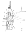
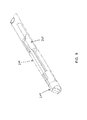
まず、図1乃至図5を見ると、本発明の1つの好ましい実施形態を備える縫合器具2が示されている。縫合器具2は、後にさらに詳細に説明するように、概して、ハンドルアセンブリ100と、カニューレアセンブリ200と、ワイヤ駆動アセンブリ300(図5)と、ワイヤ供給カートリッジ400と、を備える。
Detailed Description Overview of Preferred Embodiments Turning first to FIGS. 1-5, a
特に、後にさらに詳細に説明するように、ハンドルアセンブリ100は、ハンドル102とレバー104とを備え、カニューレアセンブリ200は、シャフト202と、エンドエフェクタ204と、ワイヤ切断機構206と、を備える。
In particular, as will be described in further detail below, the
後にさらに詳細に議論するように、概して使用中、縫合器具のエンドエフェクタ204を、縫合される対象に隣接して配置する。そして、レバー104をハンドル102に向かって押し込むことにより、ワイヤ駆動アセンブリ300が、縫合ワイヤをワイヤ供給カートリッジ400から引き出し、その縫合ワイヤを、遠位方向にカニューレアセンブリを通ってエンドエフェクタ204まで押し出す。そこで、縫合ワイヤは、対象を貫通するために十分な力で器具から出る。エンドエフェクタ204は、器具の遠位端で出る縫合ワイヤの部分をループ形状にする湾曲ダイと、器具の遠位端に戻るループ状の縫合ワイヤを収容する湾曲ガイドと、を有する。そして、エンドエフェクタ204において、ループ状の縫合ワイヤを、縫合器具を通って戻るように延在する残りの縫合ワイヤから切断することができる。かかる切断を、好ましくは、レバーのストロークの終了時にワイヤ切断機構206によって自動的に行う。
As will be discussed in more detail later, generally in use, the
後にさらに詳細に議論するように、ワイヤ供給カートリッジ400を、縫合器具2から分離して供給してもよく、その場合ワイヤ供給カートリッジ400を、縫合操作を開始する前に縫合器具2に装填する。また後により詳細に議論するように、ワイヤ供給カートリッジ440は、使用後に破棄してもよいように、使い捨てであってもよい。
As will be discussed in more detail later, the
ハンドルアセンブリ100
さらに図1乃至図5を見ると、ハンドルアセンブリ100は、ハウジング106を備え、上述したハンドル102はハウジング106に固定して取り付けられており、上述したレバー104はピボットピン108によってハウジング106に枢支接続されている。
1 to 5, the
レバー104の内端は、ロールピン112を収容するスロット110を有する。ロールピン112は、また、ラック114に固定される。ラック114は、その遠位端において圧縮ばね116に接続される。ラック114は、その長さ方向の中間においてある長さの歯118を有し、それに続いて、その近位端に平滑壁120が隣接する。この構造の結果、圧縮ばね116は通常ラック114を近位方向に付勢し、それによってレバー104がハンドル102から離れるように付勢されるが、レバー104を、ばね116の力を圧倒するようにハンドル102に向かって押し込むことができ、それによりラック114が遠位方向に移動する。レバー104の上に乗り一組の歯124に係合するつめ122(図3)を設けることにより、レバー104が1つの完全なストロークを移動しなければその近位開始位置まで戻ることができないことを確実にする。取外し可能な側板126が、ハウジング106の近位端を選択的に閉鎖する。側板126の取外し可能な性質により、後により詳細に議論するように、縫合器具に新しいワイヤ供給カートリッジ400を装填し消耗したワイヤ供給カートリッジを器具から取り除くことができる。
The inner end of the
カニューレアセンブリ20
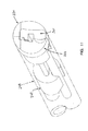
カニューレアセンブリ200を、図6乃至図16により詳細に示す。上述したように、カニューレアセンブリ200(図6)は、シャフト202と、エンドエフェクタ204と、ワイヤ切断機構206と、を備える。
Cannula assembly 20
より詳細には、シャフト202は、遠位端210と近位端212とを有する管208を備える。管208の近位端に、取付具214が固定されており、それにより、シャフト202としたがってカニューレアセンブリ200全体とを、ハンドルアセンブリ100のハウジング106に取外し可能に取り付けることができる。取付具214は、開口218(図8)を介して管208の内部と連通する、カニューレアセンブリ200の内部を清掃するための洗浄ポート216(図7)を有する。キャップ220が、洗浄ポート216を選択的に閉鎖する。
More particularly, the
エンドエフェクタ204は、管208の遠位端に固定されている。
エンドエフェクタ204は、後に議論するように、時に「縫合クリップ」または「Q形状ループ」または「Q形状クリップ」と呼ぶ、改変された縫合ループ422(図26)を形成するように構成される。
The
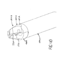
より詳細には、エンドエフェクタ204は、固定第1部222(図10、図11および図12)と固定第2部224(図10、図11および図17)とを備える。
More specifically, the
図12において分かるように、固定第1部222は、後により詳細に議論するように、上述したワイヤ供給カートリッジ400の遠位端を収容する第1チャネル226と、ワイヤ供給カートリッジ400から出てくる際の縫合ワイヤを支持する、直径がより小さい第2チャネル228と、切断棒チャネル232を通過した後の縫合ワイヤを収容しその縫合ワイヤに選択された湾曲を与え、それにより縫合ループを形成する、第3チャネル230と、を備える。第2チャネル228と第3チャネル230とは、同一平面上にある。上述したことに加えて、エンドエフェクタ204の遠位端に効果的に島236を形成するように、位置234において固定第1部222から材料を除去する。
As can be seen in FIG. 12, the fixed
第2チャネル228および第3チャネル230内を移動している間の縫合ワイヤの制御された保持を容易にするために、これらのチャネルの一方または両方に対し、第3チャネル230に対して図13に示す鳩尾型形状238等のアンダーカット形状を与えてもよい。同時に、縫合ワイヤと固定第1部222との間の有害な摩擦を最小限にするために、第2チャネル230の幅を、240(図12)以外の位置でわずかに広くしてもよい。位置240は、この特定のクリップ形態では、ワイヤ曲げをもたらす動作接点である(これに関し、他の特定のクリップ形態は他の接点を有してもよい、ということを理解するべきである)。さらに、形成された縫合クリップを器具から取り外すのを容易にするために、島236の近位端の242(図12)においてわずかに逃げを形成してもよい。
To facilitate controlled retention of the suture wire while moving in the
上述したことに加えて、器具の遠位端において、器具の遠位端に戻るループ状の縫合ワイヤを収容する湾曲ガイドを形成するように、244(図10)に示すように、固定第1部222に逃げを形成してもよい。
In addition to the above, as shown at 244 (FIG. 10), a fixed first is formed at the distal end of the instrument to form a curved guide that houses a looped suture wire that returns to the distal end of the instrument. A relief may be formed in the
ワイヤ切断機構206は、切断棒246(図8、図12および図14乃至図16)を備える。切断棒246の遠位端は、上述した切断棒チャネル232(図12)に配置され、切断棒246の近位端は、管208の近位端212から突出する(図8)。
The
切断棒246(図12および図14乃至図16)の遠位端は、好ましくは、複数の異なる面、すなわち、切断縁250を画定する切断面248と、切断面248に対して角度αに設定された逃げ面252と、排出傾斜面254と、排出押出し面258と、を備える。後により詳細に議論するように、切断棒246を、第2チャネル228と第3チャネル230との間に(したがって切断棒チャネル232を横切って)延在する縫合ワイヤにぶつかるように遠位方向に駆動すると、切断縁250は縫合ワイヤを切断し、排出傾斜面254は、切断された縫合ワイヤの後端を切断棒チャネル232からかつ島236の上方に引き上げることにより、ループを縫合器具の遠位端から外すことができるようにし、排出押出し面258は、縫合ループを縫合器具2の遠位端から押し出す。
The distal end of the cutting bar 246 (FIGS. 12 and 14-16) is preferably set to a plurality of different surfaces, namely a
切断棒246の近位端は、カニューレアセンブリ200をハンドルアセンブリ100に取り付けレバー104をハンドル102に向かって引いた場合に、レバー104によって係合され、それにより切断棒246がカニューレアセンブリ200内で遠位方向に移動するように構成されたプッシャ要素260(図2および図8)を備える。プッシャ要素260と取付具214との間に、切断棒246を近位方向に付勢するように圧縮ばね262が配置される。後により詳細に議論するように、レバー104とワイヤ切断機構206との動作は、好ましくは、レバーのストロークの後半部分までプッシャ要素260がレバー104に係合されないように互いに調整され、それにより、縫合ワイヤの前進は、切断棒246が起動されるまでには終了している。
The proximal end of the cutting
次に図10、図11および図17を見ると、固定第2部224は、上述したワイヤ供給カートリッジ400の遠位端を収容する上述した第1チャネル226の片側半分と、上述した切断棒チャネル232の片側半分と、器具の遠位端から近位方向に延在するスロット264と、を備える。後により詳細に議論するように、スロット264は、第1固定部222が第2固定部224と係合している時に、縫合ワイヤの形成されたループを縫合器具の端部から外すことができるように、島236の上部と固定第2部224の対向する材料との間に、縫合ワイヤの直径よりわずかに広い間隙が形成されるような寸法である。スロット264は、縫合ワイヤが、適当な切断および曲げに対して適所に保持されるように切断され部分的に曲げられるまで、第3チャネル230に保持されるように構成される。
Referring now to FIGS. 10, 11 and 17, the fixed
固定第1部222と固定第2部224とを、好ましくは、器具に対する摩損を最小限にするように、溝228および230を通過する縫合ワイヤより堅い材料から形成する。本発明の1つの好ましい形態では、第1固定部222と固定第2部224とを、超硬合金から形成する。
The fixation
好ましくは、切断棒246とワイヤ供給カートリッジ400の遠位端とに対し案内および支持を提供するように、管208内においてエンドエフェクタ204と取付具214との間に装填ガイド268(図8、図9および図11)を配置する。
Preferably, a loading guide 268 (FIG. 8, FIG. 8) between the
本発明の1つの好ましい形態では、エンドエフェクタ204は、その正面端部に凹部270(図12および図17)を有する。凹部270は、軟組織がエンドエフェクタ204の内部に突出するのを可能にし(図27参照)、組織内に圧入しそれに対して縫合器具を安定させる、一対の突起272、274を提供する。望ましい場合は、突起272、274の一方または両方を、補綴材料(たとえば、手術用メッシュ)の組織係合を強化しまたはその操作が容易になるように、比較的鋭利に作製してもよく、かつ/または、組織面に斜めに当てることが容易になるように、突起の一方(たとえば突起274)を他方の突起よりわずかに長く作製してもよい(たとえば図26を参照)。
In one preferred form of the invention, the
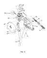
ワイヤ駆動アセンブリ300
次に図4、図5および図18乃至図21を見ると、ワイヤ駆動アセンブリ300は、固定ブロック302と、可動ブロック304と、固定ブロック302を貫通する心棒310と一方向クラッチ312とを介して平歯車308に接続された第1駆動シャフトローラ306と、心棒318と一方向クラッチ320とを介して平歯車316に接続された第2駆動シャフトローラ314と、を備える。一対の捕捉ブロック322および324が、駆動シャフトローラ306および314を夫々ブロック302および304に対して回転可能に捕捉する。
4, 5, and FIGS. 18 to 21, the
可動ブロック304は、可動ブロック304および固定ブロック302を貫通しカム従動子330に固定される一対の棒326および328を介して、固定ブロック302に摺動可能に取り付けられ、ばね332および334により可動ブロック304が固定ブロック302と係合するように付勢される。可動ブロック304を固定ブロック302から、したがって駆動シャフトローラ314を駆動シャフトローラ306から、したがって平歯車316を平歯車308から手動で引き離すためのレバー336およびカム338が設けられている。
The
ワイヤ駆動アセンブリ300は、通常、平歯車308および316がラック114の歯118と係合し、駆動シャフトローラ314が駆動シャフトローラ306と実質的に係合するように、ハンドルアセンブリ110内に配置される。
しかしながら、レバー336を押し下げることにより、カム従動子338が枢動し、それにより、可動ブロック304が固定ブロック302から引き離され、それにより、ローラ314がローラ306から分離(かつ平歯車316が平歯車308から分離)する。そこで、ワイヤ供給カートリッジ400をローラ314とローラ306との間に挿入してもよく、その後レバー336をその内向きの位置まで戻すことにより、縫合ワイヤがローラ306および314によって把持されるようにし、その時点で、縫合ワイヤを、ローラ306および314により縫合器具の遠位端から押し出すことができる。
However, depressing the
より詳細には、器具に新たなワイヤ供給カートリッジ400を取り付けた後、レバー104をハンドル102に向かって押し下げることにより、縫合ワイヤを器具の遠位端から押し出してもよい。レバー104をハンドル102に向かって押し下げることにより、ロールピン(図2)がスロット110内に乗る。より詳細には、レバー104の上端がピボットピン108を中心に回転するに従い、ロールピン112はスロット110内を移動する。これにより、ラック114が遠位方向に移動し、それにより平歯車308および316が回転し、それにより、ローラ306および314が回転し、それにより、ある長さの縫合ワイヤが前進して縫合器具の遠位端から出る。
More particularly, after attaching a new
レバー104が回転し続けるに従い、ラック114の歯のない領域(すなわち、ラック114の近位端における平滑壁120)が平歯車308および316に向かって前進し、それにより、ローラ306および314の回転が停止し、縫合ワイヤは縫合器具の遠位端からそれ以上前進しない。このため、ラックの歯118の長さを注意深く調整することにより、器具から排出される縫合ワイヤの長さもまた調整することができる、ということが分かる。
As the
そして、レバー104をさらに移動させることにより、切断棒のプッシャ要素260(図2)が係合され、それにより、切断棒246は、縫合ワイヤの形成されたループを器具に残っている縫合ワイヤから切断し、縫合ループの後端を島236の上に引き上げ、縫合ループを縫合器具から押し出すように、遠位方向に前進する。
Further movement of the
ストロークの完了時、レバー104は解放され、それにより、上述した部品がばね116の影響下でそれらの開始位置に戻ることができる。しかしながら、駆動ローラ306と駆動ローラ314と、かつ駆動ローラ306と駆動ローラ314と、の夫々の間に介挿された一方向クラッチ312および320(図19)により、駆動ローラの逆方向の移動が防止され、それによって縫合ワイヤの後退が防止される。
At the completion of the stroke, the
このように、レバー104の一投により、駆動ローラ306および314が所定の程度移動することになり、それにより、所定長の縫合ワイヤが前進して縫合器具の遠位端から出る。
Thus, a single throw of the
各駆動ローラおよび心棒アセンブリ(すなわち、駆動ローラ306および心棒310、ならびに駆動ローラ314および心棒318)を、好ましくは、同じ工具設定を使用して単一の連続した金属片から加工する(すなわち、旋削する)ことにより、それらの位置合せに、それらが異なる時に旋削され穴および保持手段を使用して組み立てられた場合に発生する可能性のある誤差がないようにする、ということを理解すべきである。この構造は、駆動ローラが、それらが駆動している縫合ワイヤの直径のおよそ30倍でありもっともわずかな位置合せ誤差でさえ前方に移動するワイヤを回転させる可能性があるため、重要である。ワイヤがエンドエフェクタ204において出口通路によって永久的に湾曲されるため、任意のかかるワイヤ回転によって、ワイヤがエンドエフェクタからその通常の経路を外れ、恐らくはワイヤの先端が、対象を貫通した後にエンドエフェクタに向かって適当に戻らなくなる可能性がある。
Each drive roller and mandrel assembly (ie,
また、駆動ローラ306および314に周縁溝を形成してもよい、ということも理解するべきである。かかる溝により、駆動されている縫合ワイヤのための台座が提供され、駆動ローラと縫合ワイヤとの間で接触する表面積が増大する。
It should also be understood that peripheral grooves may be formed in the
ワイヤ供給カートリッジ400
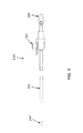
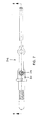
次に図22乃至図25を見ると、ワイヤ供給カートリッジ400は、概して、スプールハウジング402と、ワイヤスプール404と、スプール保持ばね406と、スプールカバー408と、成形管支持体410と、ワイヤ支持管412と、を備える。ある長さの縫合ワイヤ416が、スプール404から成形管支持体410およびワイヤ支持管412を通って延在する。
Referring now to FIGS. 22-25, the
より詳細には、縫合ワイヤ416(必要な可撓性および剛性を有する金属または他の任意の適当な材料から形成されたワイヤからなる)の供給コイルを、カートリッジ400の基部に設けてもよく、ワイヤ供給管412内に送り込む。ワイヤ支持管412は、縫合ワイヤ416をスプールハウジング402から縫合器具2の遠位端まで包囲し、そこで、ワイヤ支持管412の遠位端がチャネル226(図12)に収容されるため、縫合ワイヤはエンドエフェクタ204の第2チャネル228に入る。ワイヤ支持管412により、縫合ワイヤは、ハンドルアセンブリ100およびカニューレアセンブリ200内に押し込まれる際に曲がらずかつ歪まないことが確実になる。より詳細には、ワイヤ支持管412は、好ましくは、縫合ワイヤ416が縫合器具2内を前進する際に曲がりかつ歪むことができないように、縫合ワイヤ416との十分密な滑るかみ合い(fit)を形成する。同時にまた、ワイヤ支持管412を、縫合器具内を前進する縫合ワイヤに与える摩擦を最小にするようにも形成する。縫合ワイヤ416は極めて薄くかつ可撓性があり何らかの種類の横方向の支持がなければ曲がりまたは歪み易いため、上述した特性は重要である。
More specifically, a supply coil of suture wire 416 (consisting of a metal or any other suitable material having the necessary flexibility and rigidity) may be provided at the base of
限定としてではなく例として、縫合ワイヤ416をステンレス鋼から形成しその直径を0.017インチとする場合、ワイヤ支持管412の内径を0.185インチとし外径を0.050インチとしてもよい。さらに、ワイヤ支持管412を、好ましくは、316ステンレス鋼から形成するが、代替的に、他の何らかの材料から形成してもよい。望ましい場合、縫合ワイヤがワイヤ支持管内を密接に支持され低摩擦で通過するのを容易にするように、ワイヤ支持管412の内部を潤滑剤でコーティングしてもよい。
By way of example and not limitation, if the
ワイヤ支持管412とそれを包囲する成形管支持体410とは、その対向する側部に夫々位置合せされた開口418および420を有する。後により詳細に議論するように、開口418および420は、縫合ワイヤ416の直径方向に対向する部分を露出させることにより、ローラ306および314が縫合ワイヤ416に接触し縫合ワイヤを縫合器具2の遠位端に向かって付勢することができるようにする。
The
上述したように、可動ブロック304を固定ブロック302から引き離しそれによりローラ306および314を分離するようにレバー336を駆動することによって、ワイヤ供給カートリッジ400をワイヤ駆動アセンブリ300に装填してもよい。ローラ314がローラ306から十分な距離だけ離れると、ワイヤ支持管412をローラ306とローラ314との間に挿入してもよく、その後、ローラ306および314が夫々ワイヤ支持管412とそれを包囲する成形支持管410とのいずれかに形成された、位置合せされた開口418および420を通して、縫合ワイヤ416のいずれかの側に接触するように、ローラ314をローラ316に向けて戻してもよい。
As described above, the
動作
縫合器具2を使用して、所望の縫合操作を行うために、ワイヤ縫合416のループ422(図26)を対象に施すことができる。
Operation The
限定としてではなく例として、ここで図26乃至図33を見ると、縫合器具2を使用して、縫合されるべき対象の2つの部分500、502を合せて縫合することができる。典型的な場合では、部分500、502は、互いに再付着させる必要のある切断された組織の2つの部分からなってもよく、あるいは、互いに付着する必要のある以前は付着されていなかった2つの組織からなってもよい。しかしながら、部分500、502の一方または他方はまた、組織に付着されるべき人工メッシュまたは他の何らかの物体からなってもよい(たとえば、ヘルニア修復手術中に腹壁の内部に付着される「ヘルニアメッシュ」のようなものからなってもよい)。さらに、典型的な場合では、部分500、502は、患者内において比較的深く位置してもよく、それらを、内視鏡またはいわゆる「低侵襲的」またはいわゆる「非観血的」処置中に扱ってもよいが、他の場合、部分500、502を、従来の、すなわち「観血的」処置中に扱ってもよい。この後者の状況には、対象の身体の外面で行われる処置、すなわち、部分500、502が表面要素からなる場合が含まれてもよい。
By way of example and not limitation, looking now at FIGS. 26-33, the
いずれの場合も、最初に、ワイヤカートリッジ400がまだ取り付けられていない場合、これを縫合器具に取り付けることにより、縫合器具2を使用できるように用意する。上述したように、(1)側板126を取り除き、(2)ワイヤ駆動アセンブリの解放レバー336をその開位置に移動させることによりローラ306および314を離すように移動させ、(3)ワイヤ支持管412の遠位端がエンドエフェクタの第1チャネル226に位置するまで、カートリッジ遠位端(すなわち、ワイヤ支持管412の遠位端)を、ワイヤ駆動アセンブリ300およびカニューレアセンブリ200内に挿入し、その時点でカートリッジの成形管支持体410をローラ206および314の中間に配置し、(4)ローラ306および314が開口420および428を通して縫合ワイヤ416と係合するように、かつ、平歯車308および316がラック114の歯118に係合するように、ワイヤ駆動アセンブリの解放レバー336をその閉位置に戻るように移動させることにより、ワイヤ供給カートリッジ400を縫合器具2に取り付ける。
In either case, first, if the
この時点で、縫合器具2は使用する用意ができたことになる。
At this point, the
縫合器具2が縫合ループ422を対象に施す時、縫合器具の遠位端を対象に対向して配置し、たとえば、部分500、502に対向して配置する(図26および図27)。
When the
縫合器具2の遠位端を対象部分500、502に対向して配置すると、レバー104をハンドル102に対して後方に引く。レバー104の上端が遠位方向に移動すると、ラック114もまた遠位方向に移動し、それにより、ラックの歯118が、平歯車308および316としたがってローラ306および314とを回転させる。そして、ローラ306および314の回転により、縫合ワイヤ416が前進してワイヤ支持管412の遠位端から出る(図27)。縫合ワイヤは前進して、第2チャネル228を下り、カッタバーチャネル232(図28)を横切り、第2チャネル230を通り、その後器具から出る(図29)。溝230の形状が湾曲しているため、エンドエフェクタ204から出る縫合ワイヤはある形態を呈してループ状にねじまがり、それにより、縫合ワイヤは、縫合されるべき物質を貫通した後エンドエフェクタの固定第2部224(図30)のスロット264内に戻る。スロット264に戻るワイヤを保持するために、エンドエフェクタ204の遠位端に案内面244を設けてもよい。
When the distal end of the
望ましい場合は、エンドエフェクタの固定第2部224のスロット264の近位端276(図17)は、第3チャネル230から受け取られる縫合ワイヤ416を収容しその向きを変えるある種の偏向アンビルとして作用することができる。かかる場合、スロット264は、実際にはループ422の形成を助ける。しかしながら、本発明によれば、スロット264は縫合ワイヤ416のための偏向アンビルとして作用する必要はない。それは、ループ422の湾曲を、望ましい場合は第3チャネル230の形状のみによって与えることができるためである。
If desired, the proximal end 276 (FIG. 17) of the
縫合ワイヤ416を、所定量、すなわち、所望のループ構造を形成するための正しい量だけ前進させる。言い換えれば、「Q形状ループ」422を形成する場合、縫合ワイヤ416は、縫合ワイヤの先端424(図30)が、切断棒通路232(図31)を横切り再び器具から出て器具の前端の中間にくるまで前進する。この時点で、縫合ワイヤ416の前進は停止する。
The
上述したように、本発明の好ましい実施形態では、器具の遠位端から出て前進する縫合ワイヤの長さを、ラック114に配置された歯118の長さによって調整する。より詳細には、レバー104のハンドル102に向かう初期移動により、ラック114の歯付き部分118が平歯車308および316を通過して移動し、それにより、駆動ローラ306および314が回転し、そのため縫合ワイヤ416が前進する。レバー104をハンドル102に向かってさらに移動させることにより、ラック114の平滑壁120が平歯車308および316を通過して移動し、その結果、平歯車308および316はそれ以上移動せず、したがって縫合ワイヤ416は前進しなくなる。このように、ラック114の歯付き部分118の長さによって縫合ワイヤ駆動の程度が調整される。
As described above, in a preferred embodiment of the present invention, the length of the suture wire that exits and advances from the distal end of the instrument is adjusted by the length of the
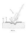
しかしながら、本発明によれば、レバー104のハンドル102に向かう連続移動により、レバーの遠位端が切断棒246の近位端260に係合し、それにより切断棒が遠位方向に駆動される(図32)。これにより、切断棒246は、(i)まず、切断棒通路232を横切って延在する縫合ワイヤの最近位部426にぶつかりそれを切断し、それによりループ422を縫合器具によって支持される縫合ワイヤの残りから分離し、(ii)その後、ループ422の端部426に対して押し進み、それにより、島236の補助によって、接合されている物質に向って端部426を曲げる。
However, according to the present invention, continuous movement of the
重要なことには、この曲げが発生している時に同時に、切断棒246がその遠位端に排出傾斜面254と排出押出し面258とを有するため、かつ、エンドエフェクタの固定第2部224がエンドエフェクタの端部に間隙を形成するスロット264を有するため、切断棒246の遠位方向の移動はまた、ループ422を島236の上方に引き上げ、それを縫合器具から押し出し、それにより、形成されたループ422を縫合器具2の遠位端から外す役割を果たす。さらに、望ましい場合は、切断棒チャネル232は、ループ422を島236の上方に引き上げるのをさらに容易にするために、ワイヤチャネル228および232の面からずれていてもよい。さらに、望ましい場合は、島236を、固定第1部222の本体に機械的に後退可能であるように形成してもよく、それにより、形成されたループ422を縫合器具から外すことがさらに容易になる。
Importantly, at the same time that this bending occurs, the cutting
ループ422が形成される方法により、ループの後端426は、形成されている材料内に向かって遠位方向に突出する(図33)。この特徴は、確実な低背の固定をもたらすため、概して非常に望ましい。
Due to the manner in which the
さまざまな要素が、ワイヤ要素が組織内でいかにループを形成するかに対して影響する可能性がある。これらの要素には、器具関連要素(たとえば、第3チャネル230の曲率等)、ワイヤ関連要素(たとえば、ワイヤ引張強度、ワイヤ降伏強さ、ワイヤ直径等)並びに組織関連要素(たとえば、組織密度、組織弾性、組織厚さ、組織安定性等)がある。 Various factors can affect how the wire element forms a loop in the tissue. These elements include instrument related elements (eg, curvature of the third channel 230), wire related elements (eg, wire tensile strength, wire yield strength, wire diameter, etc.) and tissue related elements (eg, tissue density, Tissue elasticity, tissue thickness, tissue stability, etc.).
上述した要素を、好ましくは、ワイヤループを組織内で形成する時に考慮する。たとえば、比較的繊細な組織である傾向のある腸においてループを形成する場合、比較的「軟らかい」ワイヤを使用することが概して好ましく、相応じて、比較的頑強な組織である傾向のある腹壁においてループを形成する場合は、比較的「堅い」ワイヤを使用することが概して好ましい。 The elements described above are preferably considered when forming a wire loop in tissue. For example, when forming a loop in the intestine that tends to be a relatively delicate tissue, it is generally preferred to use a relatively “soft” wire, and correspondingly in the abdominal wall that tends to be a relatively robust tissue When forming loops, it is generally preferred to use a relatively “hard” wire.
概して、特定の用途において、引張強度が230〜260kpsiであり直径が約0.006〜0.019インチである、316LVMステンレス鋼から形成された縫合ワイヤが有利である。概して、直径が約0.140〜0.165インチである縫合ループを形成する場合、半径が0.050〜0.075インチである第3チャネル230を提供することが許容可能であることが分かった。
In general, for certain applications, a suture wire formed from 316 LVM stainless steel having a tensile strength of 230-260 kpsi and a diameter of about 0.006-0.019 inches is advantageous. In general, when forming a suture loop having a diameter of about 0.140 to 0.165 inches, it has been found acceptable to provide a
望ましい場合、縫合ループ422の直径は、縫合器具の直径を超えてもよい、ということを理解するべきである。
It should be understood that the diameter of the
また、カニューレアセンブリ200をハンドルアセンブリ100から取り外すことができるという事実により、各々が異なるループ形状特性を有する、異なるカニューレアセンブリのセットを、使用時に適当な選択をすることができるようにユーザに対して提供することができる、ということも理解すべきである。
Also, due to the fact that
同様に、ワイヤ供給カートリッジ400を縫合器具2から取り外すことができるという事実により、各々が異なる縫合ワイヤ特性(たとえば、材料、硬度、直径等)を有する、異なるワイヤ供給カートリッジのセットを、使用時に適当な選択をすることができるようにユーザに対して提供することができる。
Similarly, due to the fact that the
望ましい場合、ループ422を使用して、メッシュ502を組織500に固定する、または他の物体を組織に取り付ける、または組織以外の物体を合せて付着させる等が可能である。これに関し、縫合器具を組織にメッシュを固定するために使用する場合、および、安定させる突起272、274(図12および図17)を有するエンドエフェクタ204を設ける場合、突起272、274を、好ましくは、完全にメッシュを通して延在し、下にある組織に接触するために十分幅が狭くかつ長く形成する。
If desired, the
上述したことに加えて、図26乃至図33において、縫合器具2を、物質の1つの層502を物質の下にある層500に固定するように示す。しかしながら、縫合ループ422を用いて他のタイプの付着を形成してもよい、ということも理解すべきである。このため、たとえば、図34において、2つの部分500、502をいわゆる「端と端」構造で互いに固定するように示している。
In addition to the above, in FIGS. 26-33, the
上述したように、チャネル228および230を、切断棒チャネル232の両側に配置し、それにより、チャネル228とチャネル230との間に延在する、ある長さの縫合ワイヤ426を、切断棒246によって切断することができる。これに関し、切断棒チャネル232がチャネル228と交差する角度は、縫合ワイヤ416の先端424に与えられる角度に関係している、ということが理解されよう。より詳細には、図35において、切断棒チャネル232は第2チャネル228と角度θで交差し、その結果、縫合ワイヤ416の先端もまた、角度θに設定されることが分かる。
As described above, the
概して、組織貫通の観点のみから考えると、縫合ワイヤは組織貫通を容易にするために可能な限り鋭利な先端を有するため、典型的には、角度θは可能な限り小さいことが望ましい。しかしながら、同時に、縫合ワイヤ416の先端は、第3チャネル230の実質的な湾曲を横切って移動しなければならず、角度θが小さすぎる場合、縫合ワイヤの鋭利な先端は、第3チャネル230(図36)の壁に突き当たり、それにより損傷しかつ/または鈍くなるということも理解しなければならない。一方、角度θが増大すると、先端のヒールが第3チャネル230の壁に係合し(図37)、それによって縫合ワイヤの鋭利な先端は損傷を受けない。このため、角度θは、縫合ワイヤ416の先端が可能な限り鋭利に形成されると同時に、損傷することなく第3チャネル230の湾曲を横切って移動することができるように、設定されることが概して好ましい。
In general, from the perspective of tissue penetration only, it is typically desirable for the angle θ to be as small as possible since the suture wire has as sharp a tip as possible to facilitate tissue penetration. However, at the same time, the tip of the
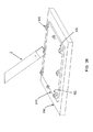
上述したように、縫合ループ422を使用して、組織を組織に固定すること、または無生物を組織に固定すること、または無生物を無生物に固定すること、等が可能である。これに関し、縫合ループ422に対する1つの予期される適用は、人工心臓弁を心臓内の弁座に固定することである、ということを理解すべきである。たとえば、縫合器具2が、人工心臓弁504を脈管組織508に固定しているように示す図38を参照する(これに関し、図38では、縫合ループ422が心臓弁504の一部をいかに穿通するかを示すために、脈管組織508の一部を取り除いていることを理解すべきである)。
As described above, the
上述した説明では、縫合ワイヤ416を、切断棒246の作用により使用時に特定の長さに切断される細長い長さ部分を備えるように説明している。しかしながら、これに関し、縫合ワイヤ416を使用前に選択された長さに事前に切断してもよく、その後その事前に切断した長さ部分を、使用時に配置するためにマガジン等に保管してもよい、ということも理解すべきである。かかる場合、切断棒246は、切断、形成および排出器具ではなく形成および排出器具として作用する。
In the above description, the
上述したように、縫合ワイヤ416は、必要な可撓性および剛性を有する金属または他の任意の適当な材料から形成されたワイヤからなってもよい。限定としてではなく例として、縫合ワイヤ416は、ステンレス鋼、チタン、タンタル等からなってもよい。
As described above, the
望ましい場合、縫合ワイヤ416を、さまざまな活性剤によってコーティングしてもよい。たとえば、縫合ワイヤ416を、抗炎症剤または抗凝血剤または抗生物質または放射性薬剤等によってコーティングしてもよい。
If desired, the
カニューレアセンブリ200A
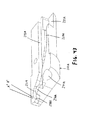
本発明の代替形態では、カニューレアセンブリ200をカニューレアセンブリ200Aに置き換えてもよい。カニューレアセンブリ200Aは、後に説明することを除き、上述したカニューレアセンブリ200と実質的に同じである。カニューレアセンブリ200Aを、図39および図40においてより詳細に示す。カニューレアセンブリ200Aは、シャフト202と、エンドエフェクタ204Aと、ワイヤ切断機構206Aと、を備える。
In an alternative form of the invention,
シャフト202は、カニューレアセンブリ200に関して上述したシャフト202と実質的に同じである。
エンドエフェクタ204Aは、シャフト管202の遠位端に固定されている。
The
エンドエフェクタ204Aを、後に議論するように、時に「改変縫合クリップ」または「改変Q形状ループ」または「Q形状クリップ」と呼ぶ改変した縫合ループ422A(図41)を形成するように構成する。
より詳細には、エンドエフェクタ204Aは、固定第1部222A(図39および図40)と固定第2部224Aとを備える。
More specifically, the
図42および図43に示すように、固定第1部222Aは、後により詳細に議論するように、上述したワイヤ供給カートリッジ400の遠位端を収容する第1チャネル226Aと、ワイヤ供給カートリッジ400から出てくる縫合ワイヤを支持する、より直径が小さい第2チャネル228Aと、切断棒チャネル232Aを通過した後の縫合ワイヤを収容しその縫合ワイヤに対し選択された湾曲を与え、それによって縫合ループを形成する、第3チャネル230Aと、を備える。第2チャネル228Aと第3チャネル230Aとは、同一平面上にある。第3チャネル230Aと切断棒チャネル232Aとは、効果的には、エンドエフェクタ204Aの遠位端において島236Aを形成する。
42 and 43, the fixed
第2チャネル228Aおよび第3チャネル230A内を移動している縫合ワイヤの制御された保持を容易にするために、これらのチャネルの一方または両方に、第3チャネル230Aに関して図43に示す鳩尾型形状238A等のアンダーカット形状を与えてもよい。同時に、縫合ワイヤと固定第1部222Aとの間の有害な摩擦を最小限にするために、第2チャネル230Aの幅を240A以外の位置でわずかに広くしてもよい(図42)。位置240Aは、この特定のクリップ形状では、ワイヤ曲げをもたらすための動作接点である(これに関し、他の特定のクリップ形態は他の接点を有してもよい、ということを理解すべきである)。
To facilitate controlled retention of the suture wire moving in the
さらに、形成された縫合クリップを器具から取り外すのを容易にするために、島236Aの近位端の242Aにおいて逃げを形成してもよく(図24)、島236Aの残りの部分に対し、形成された縫合クリップを器具から取り外すのを容易にするために243Aに示すように丸みを与えてもよい。
In addition, a relief may be formed at the
上述したことに加えて、器具の遠位端において、器具の遠位端に戻るループ状の縫合ワイヤを収容する湾曲ガイドを形成するように、244Aとして示すように固定第1部222Aに逃げを形成してもよい(図43)。
In addition to the above, at the distal end of the instrument, escape to the fixed
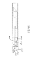
ワイヤ切断機構206Aは、切断棒246A(図44乃至図47)を備える。切断棒246Aの遠位端は、上述した切断棒チャネル232Aに配置され、切断棒246の近位端は、管208の近位端212から突出する(図8)。
The wire cutting mechanism 206A includes a cutting rod 246A (FIGS. 44 to 47). The distal end of the cutting bar 246A is disposed in the cutting
切断棒246A(図43乃至図46)の遠位端は、好ましくは、複数の別個の面、すなわち、切断縁250Aを画定する切断面248Aと、切断面248Aに対して角度αに設定された逃げ面252Aと、排出傾斜面254Aと、を備える。切断棒246Aを、第2チャネル228Aと第3チャネル230Aとの間に(したがって切断棒チャネル232Aを横切って)延在する縫合ワイヤにぶつかるように遠位方向に駆動すると、切断縁250Aは縫合ワイヤを切断し、排出傾斜面254Aは、島の逃げが形成された面242Aとともに、切断された縫合ワイヤの後端を切断棒チャネル232Aからかつ島236Aの上方に引き上げることにより、ループを縫合器具の遠位端から取り外すことができるようにする。
The distal end of the cutting bar 246A (FIGS. 43-46) is preferably set at an angle α relative to the cutting surface 248A and a plurality of separate surfaces, namely a cutting surface 248A defining a
次に図39、図40および図48を見ると、固定第2部224Aは、上述したワイヤ供給カートリッジ400の遠位端を収容する上述した第1チャネル226Aの片側部分と、上述した切断棒チャネル232Aの片側部分と、器具の遠位端から近位方向に延在する逃げ面264Aと、を有する。逃げ面264Aは、第1固定部222Aが第2固定部224Aに係合している時に、縫合ワイヤの形成されたループを縫合器具の端部から取り外すことを可能にするために、第3チャネル230Aと島236Aとが露出するように、寸法が決められている。
39, 40 and 48, the fixed
固定第1部222Aと固定第2部224Aとを、好ましくは、器具に対する摩損を最小限にするように、溝228Aおよび230Aを通過する縫合ワイヤより堅い材料から形成する。本発明の1つの好ましい形態では、第1固定部222Aと固定第2部224Aとを、超硬合金から形成する。
Fixed
本発明の1つの好ましい形態では、固定第1部222Aは、その正面端部に凹部270A(図39)を有する。固定第1部222Aの凹部270Aと固定第2部224Aの逃げ面264Aとはともに、軟組織がエンドエフェクタ204Aの内部に突出するのを可能にする。望ましい場合、器具の接合される物質との係合を容易にするために、固定第1部222Aおよび/または固定第2部224Aの一方または両方に図40の271Aに示すように逃げを形成してもよい。
In one preferred form of the present invention, the fixed
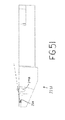
望ましい場合、ここで図29乃至図56を見ると、第3チャネル230Aの床231Aを、ループしている縫合ワイヤが第2チャネル228A面から出て移動するように傾斜させてもよく、それにより縫合ワイヤのループの形成が容易になる。例として、床231の遠位端を、ループしている縫合ワイヤが第2チャネル228Aの床の面から出て移動するように傾斜させてもよい(図49乃至図51を参照のこと)。
If desired, now referring to FIGS. 29-56, the
ワイヤ供給カートリッジ400A
本発明の代替形態では、ワイヤ供給カートリッジ400を、ワイヤ供給カートリッジ400Aに置き換えてもよい。次に図52乃至図55を見ると、ワイヤ供給カートリッジ400Aは、概して、スプールハウジング402と、ワイヤスプール404と、スプール保持ばね406と、スプールカバー408と、成形管支持体410Aと、ワイヤ支持管412Aと、を備える。ある長さの縫合ワイヤ416が、スプール404から成形管支持体410Aおよびワイヤ支持管412Aを通って延在する。
Wire supply cartridge 400A
In an alternative form of the invention, the
より詳細には、縫合ワイヤ416(必要な可撓性と剛性とを有する金属または他の任意の適当な材料から形成されたワイヤからなる)の供給コイルを、カートリッジ400Aの基部に設けてもよく、それをワイヤ支持管412Aに送り込む。ワイヤ支持管412Aは、縫合ワイヤ416を成形管支持体410Aから縫合器具2の遠位端まで包囲し、そこで、ワイヤ支持管412Aの遠位端がチャネル226(図12)に収容されるため、縫合ワイヤは、エンドエフェクタ204の第2チャネル228に入る。ワイヤ支持管412Aにより、縫合ワイヤ416が、ハンドルアセンブリ100およびカニューレアセンブリ200内に押し込まれる際に曲がらずかつ歪まないことが確実になる。より詳細には、ワイヤ支持管412Aは、好ましくは、縫合ワイヤ416が縫合器具2内を前進する際に曲がりまたは歪むことができないように、縫合ワイヤ416と十分に密な滑りばめを形成する。同時にまた、ワイヤ支持管412Aを、器具内を前進する縫合ワイヤ416に与える摩擦を最小にするように形成する。縫合ワイヤ416は極めて薄くかつ可撓性があり、何らかの種類の横方向の指示がなければ非常に曲がりまたは歪み易いため、上述した特性は重要である。
More particularly, a supply coil of suture wire 416 (consisting of a metal made of metal or any other suitable material with the necessary flexibility and rigidity) may be provided at the base of cartridge 400A. , It is fed into the
限定ではなく例示として、縫合ワイヤ416をステンレス鋼から形成しその直径を0.018インチとする場合、ワイヤ支持管412Aの内径を0.020インチとし外径を0.050インチの外径としてもよい。さらに、ワイヤ支持管412Aを、好ましくは316ステンレス鋼から形成するが、何らかの他の材料から形成してもよい。望ましい場合、縫合ワイヤがワイヤ支持管内を密接に支持され低摩擦で通過するのを容易にするように、ワイヤ支持管412Aの内部を潤滑剤でコーティングしてもよい。
By way of example and not limitation, if the
ワイヤ支持管412Aは、成形管支持体410Aの開口420Aに隣接する開口418Aで開始する。後により詳細に議論するように、開口420Aは、縫合ワイヤ416の直径方向に対向する部分を露出させることにより、ローラ306および314が縫合ワイヤ416に接触し縫合ワイヤを縫合器具2の遠位端に向かって前方に付勢することができるようにする。
The
上述したように、可動ブロック304を固定ブロック302から引き離ししそれによりローラ306とローラ314とを分離するようにレバー336を駆動することによって、ワイヤ供給カートリッジ400Aをワイヤ駆動アセンブリ300に装填してもよい。ローラ314がローラ306から十分な距離だけ離れると、ワイヤ支持管412Aをローラ306とローラ314との間に挿入してもよく、その後ローラ306および314が成形支持管410Aに形成された開口420Aを通して縫合ワイヤ416のいずれかの側に接触するように、ローラ314をローラ306に向けて戻してもよい。
As described above, the wire supply cartridge 400A may be loaded into the
本発明の他の代替形態(図示せず)では、ワイヤ供給カートリッジ400を、スプール保持ばねを有していないワイヤ供給カートリッジに置き換えてもよく、かつ/または、供給ワイヤをハウジング内にコイルとして設けてもよくスプール自体を省略してもよい。
In another alternative (not shown) of the present invention, the
変更態様
当業者には、本発明の精神および範囲から逸脱することなく上に開示した実施形態に対し多くの変更および変形を行ってもよい、ということが理解されよう。
Modifications Those skilled in the art will recognize that many changes and modifications may be made to the embodiments disclosed above without departing from the spirit and scope of the invention.
したがって、たとえば、シャフト202を、実質的に直線状であるように示したが、その長さに沿って湾曲させてもよい、ということも予期される。さらに、シャフト202は実質的に剛性であってもよく、あるいは、その長さに沿って曲げることができるように可撓性であってもよい。また、シャフト202を、エンドエフェクタ204の位置決めを容易にするように2つ以上の間接部分を有するように形成することも可能である。
Thus, for example, although
以下の図面を参照することにより、本発明は、よりよく理解されるであろう。
Claims (40)
ハンドルと、
該ハンドルに取り付けられ、その中で
縫合ワイヤを支持し、中を通過する該縫合ワイヤの一部に対しループ形状を与えるように湾曲しているチャネルと、
該チャネルから出てくる該ループ状の縫合ワイヤを収容するように構成された端凹部と、
切断棒を支持し、該チャネルと該通路との間に島を生成するように該チャネルと交差する通路と、
を画定する、エンドエフェクタと、
該ハンドルに取り付けられ、該縫合ワイヤを、該チャネルを通し該物質の第1および第2部分を通して該端凹部に戻るように移動させるワイヤ前進アクチュエータと、
該通路に移動可能に配置され、該縫合ワイヤに選択的に係合し、(1)該ループ状の縫合ワイヤを該縫合ワイヤの残り部分から切断し、(2)該ループ状の縫合ワイヤの後端を該島の周囲で曲げ、該ループ状の縫合ワイヤを該島の上に引き上げるように構成された切断棒と、
該ハンドルに取り付けられ、該切断棒を該縫合ワイヤと係合するように移動させる切断棒アクチュエータと、
を具備する縫合器具。 A suturing device for joining a first substance part to a second substance part,
A handle,
A channel attached to the handle, supporting the suture wire therein and curved to provide a loop shape for a portion of the suture wire passing therethrough;
An end recess configured to receive the looped suture wire emanating from the channel;
A passage that supports the cutting bar and intersects the channel to create an island between the channel and the passage;
Defining an end effector;
A wire advance actuator attached to the handle for moving the suture wire back through the channel and through the first and second portions of the material to the end recess;
Movably disposed in the passage and selectively engaging the suture wire; (1) cutting the looped suture wire from the rest of the suture wire; and (2) the looped suture wire A cutting bar configured to bend the rear end around the island and pull the looped suture wire over the island;
A cutting bar actuator attached to the handle and moving the cutting bar to engage the suture wire;
A suturing instrument comprising:
互いに反対の第1端部と第2端部とを有し、該第1端部がワイヤスプールから該縫合ワイヤを収容するように構成される管支持体と、
該管支持体の該第1端部と該第2端部との間に形成され、駆動するために該縫合ワイヤを露出させるように構成される開口と、
該管支持体の該第2端部に隣接して配置され、該管支持体を通して駆動される該縫合ワイヤを収容するように構成され、該縫合ワイヤを密に包囲し摺動可能に支持するように構成される管と、
を具備する構造体。 A structure that supports the suture wire during drive, comprising:
A tube support having a first end and a second end opposite to each other, the first end configured to receive the suture wire from a wire spool;
An opening formed between the first end and the second end of the tube support and configured to expose the suture wire for driving;
Located adjacent to the second end of the tube support and configured to receive the suture wire driven through the tube support and closely surrounds and slidably supports the suture wire A tube configured as
A structure comprising:
ハンドルと、
該ハンドルに取り付けられ、その中で
縫合ワイヤを支持し、中を通過する該縫合ワイヤの一部に対しループ形状を与えるように湾曲しているチャネルと、
該チャネルから出てくる該ループ状の縫合ワイヤを収容するように構成された端凹部と、
切断棒を支持し、該チャネルと該通路との間に島を生成するように該チャネルと交差する通路と、
を画定する、エンドエフェクタと、
該ハンドルに取り付けられ、該縫合ワイヤを、該チャネルを通し該物質の第1および第2部分を通して該端凹部に戻るように移動させるワイヤ前進アクチュエータと、
該通路に移動可能に配置され、該縫合ワイヤに選択的に係合し、(1)該ループ状の縫合ワイヤを該縫合ワイヤの残り部分から切断し、(2)該ループ状の縫合ワイヤの後端を該島の周囲で曲げ、該ループ状の縫合ワイヤを該島の上に引き上げるように構成された切断棒と、
該ハンドルに取り付けられ、該切断棒を該縫合ワイヤと係合するように移動させる切断棒アクチュエータと、
を備える縫合器具を提供するステップと、
該エンドエフェクタを、接合される該物質部分のうちの少なくとも一方に対向して配置するステップと、
該縫合ワイヤを、該チャネルを通し、該第1および第2物質部分を通し、該端凹部に戻るように移動させるステップと、
該切断棒を該通路において、(1)該ループ状の縫合ワイヤを該縫合ワイヤの残り部分から切断し、(2)該ループ状の縫合ワイヤの後端を該島の周囲で曲げ、該ループ状の縫合ワイヤを該島の上に引き上げるように移動させるステップと、
を含む方法。 A method of joining a first substance part to a second substance part,
A handle,
A channel attached to the handle, supporting the suture wire therein and curved to provide a loop shape for a portion of the suture wire passing therethrough;
An end recess configured to receive the looped suture wire emanating from the channel;
A passage that supports the cutting bar and intersects the channel to create an island between the channel and the passage;
Defining an end effector;
A wire advance actuator attached to the handle for moving the suture wire back through the channel and through the first and second portions of the material to the end recess;
Movably disposed in the passage and selectively engaging the suture wire; (1) cutting the looped suture wire from the rest of the suture wire; and (2) the looped suture wire A cutting bar configured to bend the rear end around the island and pull the looped suture wire over the island;
A cutting bar actuator attached to the handle and moving the cutting bar to engage the suture wire;
Providing a suturing instrument comprising:
Positioning the end effector opposite at least one of the material portions to be joined;
Moving the suture wire through the channel, through the first and second material portions, and back into the end recess;
Cutting the cutting rod in the passageway, (1) cutting the looped suture wire from the rest of the suture wire; (2) bending the rear end of the looped suture wire around the island; Moving the needle-like suture wire so as to be pulled over the island;
Including methods.
縫合ワイヤの駆動中に該縫合ワイヤを支持する構造体であって、
互いに反対の第1端部と第2端部とを有し、該第1端部がワイヤスプールから該縫合ワイヤを収容するように構成される管支持体と、
該管支持体の該第1端部と該第2端部との間に形成され、駆動するために該縫合ワイヤを露出させるように構成される開口と、
該管支持体の該第2端部に隣接して配置され、該管支持体を通して駆動される該縫合ワイヤを収容するように構成され、該縫合ワイヤを密に包囲し摺動可能に支持するように構成される管と、
を備える構造体を提供するステップと、
該縫合ワイヤを一対の対向するローラに係合させ、該対向するローラの各々が、直径方向に対向する開口の該対のうちの一方を通して該縫合ワイヤにアクセスすることにより該縫合ワイヤと係合するものである、ステップと、
を含む方法。 A method of driving a wire,
A structure that supports the suture wire during drive, comprising:
A tube support having a first end and a second end opposite to each other, the first end configured to receive the suture wire from a wire spool;
An opening formed between the first end and the second end of the tube support and configured to expose the suture wire for driving;
Located adjacent to the second end of the tube support and configured to receive the suture wire driven through the tube support and closely surrounds and slidably supports the suture wire A tube configured as
Providing a structure comprising:
Engaging the suture wire with a pair of opposed rollers, each of the opposed rollers engaging the suture wire by accessing the suture wire through one of the pair of diametrically opposed openings What to do, steps,
Including methods.
Applications Claiming Priority (2)
| Application Number | Priority Date | Filing Date | Title |
|---|---|---|---|
| US36739502P | 2002-03-25 | 2002-03-25 | |
| PCT/US2003/009114 WO2003082125A1 (en) | 2002-03-25 | 2003-03-25 | Surgical suturing instrument and method of use |
Publications (2)
| Publication Number | Publication Date |
|---|---|
| JP2005521463A true JP2005521463A (en) | 2005-07-21 |
| JP2005521463A5 JP2005521463A5 (en) | 2006-05-18 |
Family
ID=28675352
Family Applications (1)
| Application Number | Title | Priority Date | Filing Date |
|---|---|---|---|
| JP2003579672A Pending JP2005521463A (en) | 2002-03-25 | 2003-03-25 | Surgical Suture Instruments and Methods of Use References to pending applications This application is (1) published on 28 January 2003 by Frederic P. Field et al. And pending US patent application Ser. No. 10 / 352,600 (Attorney Docket No. ONUX-22CON), and (2) Gregory E. Sankov on March 4, 2003. (Gregory E. Sancoff) et al. “Pending US patent application Ser. No. 10 / 378,805, filed under the name“ SURGICALS TURRINGINSTRUMENTANDMETHODFUSE ”. (Attorney Docket No. ONUX-15CON), which is a co-pending application, which was also published on March 25, 2002 by Frederic P. Field et al. Claims the benefit of pending US Provisional Patent Application No. 60 / 367,395 (Attorney Docket No. ONUX-31PROV), filed as "SURGICALSUTURINGINSTRUMENTANDMETHODFOFUSE". This patent application also claims the benefit of. The three above-identified patent applications are hereby incorporated by reference in their entirety. |
Country Status (6)
| Country | Link |
|---|---|
| US (1) | US20040087979A1 (en) |
| EP (1) | EP1487352A4 (en) |
| JP (1) | JP2005521463A (en) |
| AU (1) | AU2003225985A1 (en) |
| CA (1) | CA2479974A1 (en) |
| WO (1) | WO2003082125A1 (en) |
Cited By (1)
| Publication number | Priority date | Publication date | Assignee | Title |
|---|---|---|---|---|
| JPWO2015076317A1 (en) * | 2013-11-19 | 2017-03-16 | 日本碍子株式会社 | Thermal insulation film and thermal insulation film structure |
Families Citing this family (55)
| Publication number | Priority date | Publication date | Assignee | Title |
|---|---|---|---|---|
| US6332889B1 (en) * | 1998-08-27 | 2001-12-25 | Onux Medical, Inc. | Surgical suturing instrument and method of use |
| US6527785B2 (en) * | 1999-08-03 | 2003-03-04 | Onux Medical, Inc. | Surgical suturing instrument and method of use |
| ITCE990004A1 (en) | 1999-10-25 | 2000-01-25 | Mario Immacolato Paternuosto | VALVE FOR BIOPSY FORCEPS IN DIGESTIVE ENDOSCOPY |
| US6679895B1 (en) * | 1999-11-05 | 2004-01-20 | Onux Medical, Inc. | Apparatus and method for placing suture wires into tissue for the approximation and tensioning of tissue |
| US6663643B2 (en) * | 2000-03-27 | 2003-12-16 | Onux Medical, Inc. | Surgical suturing instrument and method of use |
| EP1331887A4 (en) | 2000-10-20 | 2006-07-12 | Dvl Acquisition Sub Inc | Surgical suturing instrument and method of use |
| US7011668B2 (en) * | 2001-07-23 | 2006-03-14 | Dvl Acquistion Sub, Inc. | Surgical suturing instrument and method of use |
| AU2002326917A1 (en) * | 2001-09-14 | 2003-04-01 | Onux Medical, Inc. | Surgical suturing instrument and method of use |
| AU2003241521A1 (en) * | 2002-05-17 | 2003-12-02 | Onux Medical, Inc. | Surgical suturing instrument and method of use |
| CA2484870A1 (en) * | 2002-05-17 | 2003-11-27 | Dvl Acquisition Sub, Inc. | Surgical suturing instrument and method of use |
| FR2842724B1 (en) | 2002-07-23 | 2005-05-27 | Spine Next Sa | VERTEBRAL FASTENING SYSTEM |
| US20040260337A1 (en) | 2003-06-18 | 2004-12-23 | Scimed Life Systems, Inc. | Endoscopic instruments and methods of manufacture |
| US8469993B2 (en) | 2003-06-18 | 2013-06-25 | Boston Scientific Scimed, Inc. | Endoscopic instruments |
| US7588545B2 (en) | 2003-09-10 | 2009-09-15 | Boston Scientific Scimed, Inc. | Forceps and collection assembly with accompanying mechanisms and related methods of use |
| US7942896B2 (en) * | 2003-11-25 | 2011-05-17 | Scimed Life Systems, Inc. | Forceps and collection assembly and related methods of use and manufacture |
| US7297149B2 (en) | 2005-04-14 | 2007-11-20 | Ethicon Endo-Surgery, Inc. | Surgical clip applier methods |
| US7686820B2 (en) | 2005-04-14 | 2010-03-30 | Ethicon Endo-Surgery, Inc. | Surgical clip applier ratchet mechanism |
| US7288098B2 (en) | 2005-04-14 | 2007-10-30 | Ethicon Endo-Surgery, Inc. | Force limiting mechanism for medical instrument |
| US8523882B2 (en) | 2005-04-14 | 2013-09-03 | Ethicon Endo-Surgery, Inc. | Clip advancer mechanism with alignment features |
| US7740641B2 (en) | 2005-04-14 | 2010-06-22 | Ethicon Endo-Surgery, Inc. | Clip applier with migrational resistance features |
| US8038686B2 (en) | 2005-04-14 | 2011-10-18 | Ethicon Endo-Surgery, Inc. | Clip applier configured to prevent clip fallout |
| US7261724B2 (en) | 2005-04-14 | 2007-08-28 | Ethicon Endo-Surgery, Inc. | Surgical clip advancement mechanism |
| US7762960B2 (en) | 2005-05-13 | 2010-07-27 | Boston Scientific Scimed, Inc. | Biopsy forceps assemblies |
| FR2890850B1 (en) * | 2005-09-20 | 2009-04-17 | Abbott Spine Sa | VERTEBRAL FASTENING SYSTEM |
| FR2890851B1 (en) | 2005-09-21 | 2008-06-20 | Abbott Spine Sa | ANCILLARY TO TENSION A FLEXIBLE LINK. |
| US8105355B2 (en) | 2006-05-18 | 2012-01-31 | C.R. Bard, Inc. | Suture lock fastening device |
| EP2047813A1 (en) | 2007-10-11 | 2009-04-15 | Abbott Spine | Bone fixing system and method of use |
| US8128635B2 (en) * | 2007-10-23 | 2012-03-06 | Zimmer Spine S.A.S. | Bone fixation tensioning tool and method |
| EP2052689B1 (en) * | 2007-10-23 | 2011-12-14 | Zimmer Spine | Fixing devices and stabilization systems using said fixing devices |
| FR2924917B1 (en) * | 2007-12-13 | 2011-02-11 | Microval | APPARATUS FOR INSTALLING SUTURE SPIERS RESULTING FROM A SHAPE MEMORY METAL WIRE. |
| US9301826B2 (en) | 2008-02-18 | 2016-04-05 | Covidien Lp | Lock bar spring and clip for implant deployment device |
| US9393093B2 (en) | 2008-02-18 | 2016-07-19 | Covidien Lp | Clip for implant deployment device |
| EP2247245B1 (en) | 2008-02-18 | 2017-06-28 | Covidien LP | A device for deploying and attaching a patch to a biological tissue |
| US9044235B2 (en) | 2008-02-18 | 2015-06-02 | Covidien Lp | Magnetic clip for implant deployment device |
| US8808314B2 (en) | 2008-02-18 | 2014-08-19 | Covidien Lp | Device and method for deploying and attaching an implant to a biological tissue |
| US8758373B2 (en) | 2008-02-18 | 2014-06-24 | Covidien Lp | Means and method for reversibly connecting a patch to a patch deployment device |
| US9034002B2 (en) | 2008-02-18 | 2015-05-19 | Covidien Lp | Lock bar spring and clip for implant deployment device |
| US9393002B2 (en) | 2008-02-18 | 2016-07-19 | Covidien Lp | Clip for implant deployment device |
| US9398944B2 (en) | 2008-02-18 | 2016-07-26 | Covidien Lp | Lock bar spring and clip for implant deployment device |
| US9833240B2 (en) | 2008-02-18 | 2017-12-05 | Covidien Lp | Lock bar spring and clip for implant deployment device |
| US8317808B2 (en) | 2008-02-18 | 2012-11-27 | Covidien Lp | Device and method for rolling and inserting a prosthetic patch into a body cavity |
| US20090248077A1 (en) * | 2008-03-31 | 2009-10-01 | Derrick William Johns | Hybrid dynamic stabilization |
| CA2730547C (en) | 2008-10-20 | 2013-08-06 | Polytouch Medical Ltd. | A device for attaching a patch to a biological tissue |
| WO2011021082A1 (en) | 2009-08-17 | 2011-02-24 | PolyTouch Medical, Inc. | Means and method for reversibly connecting an implant to a deployment device |
| US8906045B2 (en) | 2009-08-17 | 2014-12-09 | Covidien Lp | Articulating patch deployment device and method of use |
| US8262679B2 (en) | 2009-10-09 | 2012-09-11 | Ethicon Endo-Surgery, Inc. | Clip advancer |
| US8267945B2 (en) | 2009-10-09 | 2012-09-18 | Ethicon Endo-Surgery, Inc. | Clip advancer with lockout mechanism |
| WO2013059432A1 (en) | 2011-10-19 | 2013-04-25 | Ethicon Endo-Surgery, Inc. | Clip applier adapted for use with a surgical robot |
| US20150133968A1 (en) | 2012-05-01 | 2015-05-14 | Jon Einarsson | Suturing device for laparoscopic procedures |
| US9974676B2 (en) | 2013-08-09 | 2018-05-22 | Cook Medical Technologies Llc | Wire collection device with geared advantage |
| US9974677B2 (en) | 2013-08-20 | 2018-05-22 | Cook Medical Technologies Llc | Wire collection device for stent delivery system |
| WO2015050999A1 (en) * | 2013-10-02 | 2015-04-09 | Kia Michael Amirfarzad | A suture device |
| US9974678B2 (en) * | 2014-03-10 | 2018-05-22 | Cook Medical Technologies Llc | Wire collection device with varying collection diameter |
| US10683158B2 (en) | 2017-01-26 | 2020-06-16 | Pelican Biothermal, Llc | Protectively framed and covered thermal insulation panel |
| EP3917412A4 (en) * | 2019-01-31 | 2023-02-15 | MVRx, Inc. | Suture management device and methods |
Family Cites Families (94)
| Publication number | Priority date | Publication date | Assignee | Title |
|---|---|---|---|---|
| US919138A (en) * | 1909-03-16 | 1909-04-20 | Clarence A Drake | Surgical needle. |
| US1449087A (en) * | 1921-12-05 | 1923-03-20 | Edwin P Bugbee | Suturing instrument |
| US3584628A (en) * | 1968-10-11 | 1971-06-15 | United States Surgical Corp | Wire suture wrapping instrument |
| US3735762A (en) * | 1970-04-27 | 1973-05-29 | Us Corp Baltimo E | Instrument for ligating suturing and dividing organic tubular structures |
| US3675688A (en) * | 1970-04-27 | 1972-07-11 | United States Surgical Corp | Instrument for ligating, suturing and dividing organic tubular structures |
| US3807407A (en) * | 1971-06-07 | 1974-04-30 | E Schweizer | Suture applicator |
| US3858783A (en) * | 1972-11-20 | 1975-01-07 | Nikolai Nikolaevich Kapitanov | Surgical instrument for stitching up tissues with lengths of suture wire |
| US3877570A (en) * | 1973-07-25 | 1975-04-15 | Robert J Barry | Sterile cosmetic suture for attaching hair pieces to scalp and method of packaging and utilizing |
| US3959960A (en) * | 1975-03-12 | 1976-06-01 | Santos Manuel V | Tensioning, twisting and cutting device for sutures |
| US4006747A (en) * | 1975-04-23 | 1977-02-08 | Ethicon, Inc. | Surgical method |
| US4027608A (en) * | 1976-02-20 | 1977-06-07 | Raymond Kelder | Suturing device |
| SU715082A1 (en) * | 1977-01-24 | 1980-02-15 | Всесоюзный научно-исследовательский и испытательный институт медицинской техники | Surgical suturing apparatus |
| US5133727A (en) * | 1990-05-10 | 1992-07-28 | Symbiosis Corporation | Radial jaw biopsy forceps |
| US4258716A (en) * | 1978-02-06 | 1981-03-31 | The University Of Melbourne | Microsurgical instruments |
| US4453661A (en) * | 1980-10-23 | 1984-06-12 | Ivano-Frankovsky Gosudarstvenny Meditsinsky Institut | Surgical instrument for applying staples |
| DE3103352C2 (en) * | 1981-01-31 | 1982-10-21 | Aesculap-Werke Ag Vormals Jetter & Scheerer, 7200 Tuttlingen | Forceps or forceps shaped surgical instrument |
| US4741330A (en) * | 1983-05-19 | 1988-05-03 | Hayhurst John O | Method and apparatus for anchoring and manipulating cartilage |
| US4602636A (en) * | 1983-03-08 | 1986-07-29 | Joint Medical Products Corporation | Suture wire with integral needle-like tip |
| US4595007A (en) * | 1983-03-14 | 1986-06-17 | Ethicon, Inc. | Split ring type tissue fastener |
| US4644651A (en) * | 1984-03-19 | 1987-02-24 | Jacobsen Research Corp. | Instrument for gripping or cutting |
| US4583541A (en) * | 1984-05-07 | 1986-04-22 | Barry Joseph P | Sternal stabilization device |
| DE8418993U1 (en) * | 1984-06-23 | 1984-09-20 | Richard Wolf Gmbh, 7134 Knittlingen | Medical forceps |
| US4669473A (en) * | 1985-09-06 | 1987-06-02 | Acufex Microsurgical, Inc. | Surgical fastener |
| ES2018173B3 (en) * | 1986-01-30 | 1991-04-01 | Pfaff Ind Masch | SURGICAL SEWING MACHINE AND PROCEDURE FOR CONFORMING STITCHES IN A TISSUE ORLA |
| US4803984A (en) * | 1987-07-06 | 1989-02-14 | Montefiore Hospital Association Of Western Pennsylvania | Method for performing small vessel anastomosis |
| US4819635A (en) * | 1987-09-18 | 1989-04-11 | Henry Shapiro | Tubular microsurgery cutting apparatus |
| US4890615B1 (en) * | 1987-11-05 | 1993-11-16 | Linvatec Corporation | Arthroscopic suturing instrument |
| IT1216042B (en) * | 1988-03-09 | 1990-02-22 | Carlo Rebuffat | AUTOMATIC TOOL FOR TOBACCO BAG SUTURES FOR SURGICAL USE. |
| US4901721A (en) * | 1988-08-02 | 1990-02-20 | Hakki Samir I | Suturing device |
| EP0386285A1 (en) * | 1989-03-07 | 1990-09-12 | Ricerche Biomediche S.R.L. | Improvements in automatic mechanic suturing guns |
| US5002564A (en) * | 1989-06-19 | 1991-03-26 | Ethicon, Inc. | Surgical needle configuration with spatula geometry |
| US4935027A (en) * | 1989-08-21 | 1990-06-19 | Inbae Yoon | Surgical suture instrument with remotely controllable suture material advancement |
| US5021059A (en) * | 1990-05-07 | 1991-06-04 | Kensey Nash Corporation | Plug device with pulley for sealing punctures in tissue and methods of use |
| US5219357A (en) * | 1990-05-31 | 1993-06-15 | Tnco, Inc. | Micro-instrument |
| US5211650A (en) * | 1991-01-07 | 1993-05-18 | Laparomed Corporation | Dual function suturing device and method |
| DK166600B1 (en) * | 1991-01-17 | 1993-06-21 | Therkel Bisgaard | TOOL USE TOUCH BY SUTURING IN DEEP OPERATING OPENINGS OR BODY SPACES |
| US5217465A (en) * | 1992-02-28 | 1993-06-08 | Alcon Surgical, Inc. | Flexible and steerable aspiration tip for microsurgery |
| US5304183A (en) * | 1992-03-23 | 1994-04-19 | Laparomed Corporation | Tethered clamp retractor |
| US5417700A (en) * | 1992-03-30 | 1995-05-23 | Thomas D. Egan | Automatic suturing and ligating device |
| US5290284A (en) * | 1992-05-01 | 1994-03-01 | Adair Edwin Lloyd | Laparoscopic surgical ligation and electrosurgical coagulation and cutting device |
| DE4217202C2 (en) * | 1992-05-23 | 1994-06-23 | Kernforschungsz Karlsruhe | Surgical sewing instrument |
| US5334199A (en) * | 1992-08-17 | 1994-08-02 | Inbae Yoon | Ligating instrument and methods of ligating tissue in endoscopic operative procedures |
| US5308357A (en) * | 1992-08-21 | 1994-05-03 | Microsurge, Inc. | Handle mechanism for manual instruments |
| US5308353A (en) * | 1992-08-31 | 1994-05-03 | Merrimac Industries, Inc. | Surgical suturing device |
| US5306281A (en) * | 1992-08-31 | 1994-04-26 | Merrimac Industries, Inc. | Suturing cassette device |
| US6048351A (en) * | 1992-09-04 | 2000-04-11 | Scimed Life Systems, Inc. | Transvaginal suturing system |
| US5713910A (en) * | 1992-09-04 | 1998-02-03 | Laurus Medical Corporation | Needle guidance system for endoscopic suture device |
| US5522820A (en) * | 1993-01-15 | 1996-06-04 | Arthrotech | Method and apparatus for suturing tissue |
| US5417701A (en) * | 1993-03-30 | 1995-05-23 | Holmed Corporation | Surgical instrument with magnetic needle holder |
| DE4310555C1 (en) * | 1993-03-31 | 1993-12-09 | Strobel & Soehne Gmbh & Co J | Surgical machine stitching tissue edges together - has forceps opening and shutting in synchronism with needle to hold edges together before puncturing |
| US5498256A (en) * | 1993-05-28 | 1996-03-12 | Snowden-Pencer, Inc. | Surgical instrument handle |
| US5386741A (en) * | 1993-06-07 | 1995-02-07 | Rennex; Brian G. | Robotic snake |
| US5372604A (en) * | 1993-06-18 | 1994-12-13 | Linvatec Corporation | Suture anchor for soft tissue fixation |
| US5527321A (en) * | 1993-07-14 | 1996-06-18 | United States Surgical Corporation | Instrument for closing trocar puncture wounds |
| US5411522A (en) * | 1993-08-25 | 1995-05-02 | Linvatec Corporation | Unitary anchor for soft tissue fixation |
| US5324308A (en) * | 1993-10-28 | 1994-06-28 | Javin Pierce | Suture anchor |
| US5527322A (en) * | 1993-11-08 | 1996-06-18 | Perclose, Inc. | Device and method for suturing of internal puncture sites |
| US5423821A (en) * | 1994-01-18 | 1995-06-13 | Pasque; Michael K. | Sternal closure device |
| US5501692A (en) * | 1994-01-28 | 1996-03-26 | Riza; Erol D. | Laparoscopic suture snare |
| US5501698A (en) * | 1994-02-14 | 1996-03-26 | Heartport, Inc. | Endoscopic microsurgical instruments and methods |
| US5501688A (en) * | 1994-02-17 | 1996-03-26 | Surgical Accessories, Inc. | Surgical device for manipulating wire |
| US5522843A (en) * | 1994-02-23 | 1996-06-04 | Orthopaedic Biosystems Limited, Inc. | Apparatus for attaching soft tissue to bone |
| US5582616A (en) * | 1994-08-05 | 1996-12-10 | Origin Medsystems, Inc. | Surgical helical fastener with applicator |
| US5728112A (en) * | 1995-09-22 | 1998-03-17 | Yoon; Inbae | Combined tissue clamping and suturing instrument |
| US5911727A (en) * | 1996-02-20 | 1999-06-15 | Cardiothoracic Systems, Inc. | Stitcher |
| US5709693A (en) * | 1996-02-20 | 1998-01-20 | Cardiothoracic System, Inc. | Stitcher |
| US5755728A (en) * | 1996-03-07 | 1998-05-26 | Maki; Neil J. | Suture apparatus with loop end portions |
| US5766217A (en) * | 1996-09-23 | 1998-06-16 | Christy; William J. | Surgical loop delivery device and method |
| US5759188A (en) * | 1996-11-27 | 1998-06-02 | Yoon; Inbae | Suturing instrument with rotatably mounted needle driver and catcher |
| US5766186A (en) * | 1996-12-03 | 1998-06-16 | Simon Fraser University | Suturing device |
| US5891140A (en) * | 1996-12-23 | 1999-04-06 | Cardiothoracic Systems, Inc. | Electrosurgical device for harvesting a vessel especially the internal mammary artery for coronary artery bypass grafting |
| US5972005A (en) * | 1998-02-17 | 1999-10-26 | Advanced Cardiovascular Systems, Ind. | Wound closure assembly and method of use |
| US6015416A (en) * | 1998-02-26 | 2000-01-18 | Ethicon Endo-Surgery, Inc. | Surgical anastomosis instrument |
| US6332889B1 (en) * | 1998-08-27 | 2001-12-25 | Onux Medical, Inc. | Surgical suturing instrument and method of use |
| US6767352B2 (en) * | 1999-08-03 | 2004-07-27 | Onux Medical, Inc. | Surgical suturing instrument and method of use |
| US6511489B2 (en) * | 1999-08-03 | 2003-01-28 | Frederic P. Field | Surgical suturing instrument and method of use |
| US6527785B2 (en) * | 1999-08-03 | 2003-03-04 | Onux Medical, Inc. | Surgical suturing instrument and method of use |
| US6682540B1 (en) * | 1999-11-05 | 2004-01-27 | Onux Medical, Inc. | Apparatus and method for placing multiple sutures |
| WO2001034035A1 (en) * | 1999-11-05 | 2001-05-17 | Onux Medical, Inc. | Apparatus and method for approximating and closing the walls of a hole or puncture in a physiological shell structure |
| US6679895B1 (en) * | 1999-11-05 | 2004-01-20 | Onux Medical, Inc. | Apparatus and method for placing suture wires into tissue for the approximation and tensioning of tissue |
| US6663643B2 (en) * | 2000-03-27 | 2003-12-16 | Onux Medical, Inc. | Surgical suturing instrument and method of use |
| US6520973B1 (en) * | 2000-08-30 | 2003-02-18 | Ethicon Endo-Surgery, Inc. | Anastomosis device having an improved needle driver |
| US6530932B1 (en) * | 2000-08-30 | 2003-03-11 | Ethicon Endo-Surgery, Inc. | Anastomosis device having improved tissue presentation |
| US6514263B1 (en) * | 2000-08-30 | 2003-02-04 | Ethicon Endo-Surgery, Inc. | Helical needle and suture combination having a strain relief element |
| AU2001292563A1 (en) * | 2000-09-01 | 2002-03-13 | Advanced Vascular Technologies, Llc | Multi-fastener surgical apparatus and method |
| EP1331887A4 (en) * | 2000-10-20 | 2006-07-12 | Dvl Acquisition Sub Inc | Surgical suturing instrument and method of use |
| US6740099B1 (en) * | 2000-10-20 | 2004-05-25 | Mark Doyle | Surgical tool for trimming wire strands |
| US7615059B2 (en) * | 2001-05-30 | 2009-11-10 | Ams Research Corporation | Surgical suture passers and methods |
| US7011668B2 (en) * | 2001-07-23 | 2006-03-14 | Dvl Acquistion Sub, Inc. | Surgical suturing instrument and method of use |
| US7112208B2 (en) * | 2001-08-06 | 2006-09-26 | Morris John K | Compact suture punch with malleable needle |
| AU2002326917A1 (en) * | 2001-09-14 | 2003-04-01 | Onux Medical, Inc. | Surgical suturing instrument and method of use |
| WO2003088815A2 (en) * | 2002-04-17 | 2003-10-30 | Tyco Healthcare Group, Lp | Tacking tool and tack |
| AU2003241521A1 (en) * | 2002-05-17 | 2003-12-02 | Onux Medical, Inc. | Surgical suturing instrument and method of use |
| US20040073237A1 (en) * | 2002-10-08 | 2004-04-15 | Leinsing Karl R. | Surgical fastener and delivery system |
-
2003
- 2003-03-25 EP EP03745595A patent/EP1487352A4/en not_active Withdrawn
- 2003-03-25 US US10/396,927 patent/US20040087979A1/en not_active Abandoned
- 2003-03-25 CA CA002479974A patent/CA2479974A1/en not_active Abandoned
- 2003-03-25 JP JP2003579672A patent/JP2005521463A/en active Pending
- 2003-03-25 AU AU2003225985A patent/AU2003225985A1/en not_active Abandoned
- 2003-03-25 WO PCT/US2003/009114 patent/WO2003082125A1/en active Application Filing
Cited By (1)
| Publication number | Priority date | Publication date | Assignee | Title |
|---|---|---|---|---|
| JPWO2015076317A1 (en) * | 2013-11-19 | 2017-03-16 | 日本碍子株式会社 | Thermal insulation film and thermal insulation film structure |
Also Published As
| Publication number | Publication date |
|---|---|
| EP1487352A4 (en) | 2006-07-12 |
| WO2003082125A1 (en) | 2003-10-09 |
| CA2479974A1 (en) | 2003-10-09 |
| AU2003225985A1 (en) | 2003-10-13 |
| US20040087979A1 (en) | 2004-05-06 |
| EP1487352A1 (en) | 2004-12-22 |
Similar Documents
| Publication | Publication Date | Title |
|---|---|---|
| JP2005521463A (en) | Surgical Suture Instruments and Methods of Use References to pending applications This application is (1) published on 28 January 2003 by Frederic P. Field et al. And pending US patent application Ser. No. 10 / 352,600 (Attorney Docket No. ONUX-22CON), and (2) Gregory E. Sankov on March 4, 2003. (Gregory E. Sancoff) et al. “Pending US patent application Ser. No. 10 / 378,805, filed under the name“ SURGICALS TURRINGINSTRUMENTANDMETHODFUSE ”. (Attorney Docket No. ONUX-15CON), which is a co-pending application, which was also published on March 25, 2002 by Frederic P. Field et al. Claims the benefit of pending US Provisional Patent Application No. 60 / 367,395 (Attorney Docket No. ONUX-31PROV), filed as "SURGICALSUTURINGINSTRUMENTANDMETHODFOFUSE". This patent application also claims the benefit of. The three above-identified patent applications are hereby incorporated by reference in their entirety. | |
| CA2426552C (en) | Surgical suturing instrument and method of use | |
| US6663643B2 (en) | Surgical suturing instrument and method of use | |
| US6511489B2 (en) | Surgical suturing instrument and method of use | |
| JP2005525866A (en) | Surgical suture instrument and method of use thereof | |
| US9549728B2 (en) | Placing multiple sutures | |
| US6527785B2 (en) | Surgical suturing instrument and method of use | |
| US6767352B2 (en) | Surgical suturing instrument and method of use | |
| JP4907546B2 (en) | Apparatus and method for supplying fasteners during valve replacement | |
| CA2342329C (en) | Surgical suturing instrument and method of use | |
| US20070088372A1 (en) | Suturing instrument with deflectable head | |
| CA2404193C (en) | Surgical suturing instrument and method of use | |
| WO2002038036A2 (en) | Surgical suturing instrument and method of use |
Legal Events
| Date | Code | Title | Description |
|---|---|---|---|
| A521 | Written amendment |
Free format text: JAPANESE INTERMEDIATE CODE: A523 Effective date: 20051213 |
|
| A711 | Notification of change in applicant |
Free format text: JAPANESE INTERMEDIATE CODE: A711 Effective date: 20051213 |
|
| A521 | Written amendment |
Free format text: JAPANESE INTERMEDIATE CODE: A523 Effective date: 20060324 |
|
| A621 | Written request for application examination |
Free format text: JAPANESE INTERMEDIATE CODE: A621 Effective date: 20060324 |
|
| A131 | Notification of reasons for refusal |
Free format text: JAPANESE INTERMEDIATE CODE: A131 Effective date: 20090402 |
|
| A601 | Written request for extension of time |
Free format text: JAPANESE INTERMEDIATE CODE: A601 Effective date: 20090701 |
|
| A602 | Written permission of extension of time |
Free format text: JAPANESE INTERMEDIATE CODE: A602 Effective date: 20090708 |
|
| A02 | Decision of refusal |
Free format text: JAPANESE INTERMEDIATE CODE: A02 Effective date: 20091009 |