JP2005518320A - System and method for object tracking using a visual sensing indicator - Google Patents
System and method for object tracking using a visual sensing indicator Download PDFInfo
- Publication number
- JP2005518320A JP2005518320A JP2003560656A JP2003560656A JP2005518320A JP 2005518320 A JP2005518320 A JP 2005518320A JP 2003560656 A JP2003560656 A JP 2003560656A JP 2003560656 A JP2003560656 A JP 2003560656A JP 2005518320 A JP2005518320 A JP 2005518320A
- Authority
- JP
- Japan
- Prior art keywords
- objects
- identifier
- image
- visual sensing
- tracking system
- Prior art date
- Legal status (The legal status is an assumption and is not a legal conclusion. Google has not performed a legal analysis and makes no representation as to the accuracy of the status listed.)
- Pending
Links
Images


Classifications
-
- G—PHYSICS
- G06—COMPUTING; CALCULATING OR COUNTING
- G06K—GRAPHICAL DATA READING; PRESENTATION OF DATA; RECORD CARRIERS; HANDLING RECORD CARRIERS
- G06K19/00—Record carriers for use with machines and with at least a part designed to carry digital markings
- G06K19/06—Record carriers for use with machines and with at least a part designed to carry digital markings characterised by the kind of the digital marking, e.g. shape, nature, code
- G06K19/06009—Record carriers for use with machines and with at least a part designed to carry digital markings characterised by the kind of the digital marking, e.g. shape, nature, code with optically detectable marking
- G06K19/06046—Constructional details
-
- G—PHYSICS
- G06—COMPUTING; CALCULATING OR COUNTING
- G06K—GRAPHICAL DATA READING; PRESENTATION OF DATA; RECORD CARRIERS; HANDLING RECORD CARRIERS
- G06K17/00—Methods or arrangements for effecting co-operative working between equipments covered by two or more of main groups G06K1/00 - G06K15/00, e.g. automatic card files incorporating conveying and reading operations
-
- G—PHYSICS
- G06—COMPUTING; CALCULATING OR COUNTING
- G06K—GRAPHICAL DATA READING; PRESENTATION OF DATA; RECORD CARRIERS; HANDLING RECORD CARRIERS
- G06K19/00—Record carriers for use with machines and with at least a part designed to carry digital markings
- G06K19/06—Record carriers for use with machines and with at least a part designed to carry digital markings characterised by the kind of the digital marking, e.g. shape, nature, code
- G06K19/06009—Record carriers for use with machines and with at least a part designed to carry digital markings characterised by the kind of the digital marking, e.g. shape, nature, code with optically detectable marking
-
- G—PHYSICS
- G06—COMPUTING; CALCULATING OR COUNTING
- G06K—GRAPHICAL DATA READING; PRESENTATION OF DATA; RECORD CARRIERS; HANDLING RECORD CARRIERS
- G06K19/00—Record carriers for use with machines and with at least a part designed to carry digital markings
- G06K19/06—Record carriers for use with machines and with at least a part designed to carry digital markings characterised by the kind of the digital marking, e.g. shape, nature, code
- G06K19/067—Record carriers with conductive marks, printed circuits or semiconductor circuit elements, e.g. credit or identity cards also with resonating or responding marks without active components
- G06K19/07—Record carriers with conductive marks, printed circuits or semiconductor circuit elements, e.g. credit or identity cards also with resonating or responding marks without active components with integrated circuit chips
- G06K19/0716—Record carriers with conductive marks, printed circuits or semiconductor circuit elements, e.g. credit or identity cards also with resonating or responding marks without active components with integrated circuit chips at least one of the integrated circuit chips comprising a sensor or an interface to a sensor
- G06K19/0717—Record carriers with conductive marks, printed circuits or semiconductor circuit elements, e.g. credit or identity cards also with resonating or responding marks without active components with integrated circuit chips at least one of the integrated circuit chips comprising a sensor or an interface to a sensor the sensor being capable of sensing environmental conditions such as temperature history or pressure
-
- G—PHYSICS
- G06—COMPUTING; CALCULATING OR COUNTING
- G06K—GRAPHICAL DATA READING; PRESENTATION OF DATA; RECORD CARRIERS; HANDLING RECORD CARRIERS
- G06K7/00—Methods or arrangements for sensing record carriers, e.g. for reading patterns
- G06K7/10—Methods or arrangements for sensing record carriers, e.g. for reading patterns by electromagnetic radiation, e.g. optical sensing; by corpuscular radiation
- G06K7/10544—Methods or arrangements for sensing record carriers, e.g. for reading patterns by electromagnetic radiation, e.g. optical sensing; by corpuscular radiation by scanning of the records by radiation in the optical part of the electromagnetic spectrum
- G06K7/10821—Methods or arrangements for sensing record carriers, e.g. for reading patterns by electromagnetic radiation, e.g. optical sensing; by corpuscular radiation by scanning of the records by radiation in the optical part of the electromagnetic spectrum further details of bar or optical code scanning devices
- G06K7/1095—Methods or arrangements for sensing record carriers, e.g. for reading patterns by electromagnetic radiation, e.g. optical sensing; by corpuscular radiation by scanning of the records by radiation in the optical part of the electromagnetic spectrum further details of bar or optical code scanning devices the scanner comprising adaptations for scanning a record carrier that is displayed on a display-screen or the like
-
- G—PHYSICS
- G06—COMPUTING; CALCULATING OR COUNTING
- G06K—GRAPHICAL DATA READING; PRESENTATION OF DATA; RECORD CARRIERS; HANDLING RECORD CARRIERS
- G06K7/00—Methods or arrangements for sensing record carriers, e.g. for reading patterns
- G06K7/10—Methods or arrangements for sensing record carriers, e.g. for reading patterns by electromagnetic radiation, e.g. optical sensing; by corpuscular radiation
- G06K7/14—Methods or arrangements for sensing record carriers, e.g. for reading patterns by electromagnetic radiation, e.g. optical sensing; by corpuscular radiation using light without selection of wavelength, e.g. sensing reflected white light
Abstract
追跡中のオブジェクト上の視覚感知インジケータと、視覚感知インジケータも示す追跡中のオブジェクトの画像を捕捉する少なくとも1つのイメージャと、少なくとも1つのイメージャの出力を受信してその出力から視覚感知インジケータが示す符号化された情報を抽出する少なくとも1つの画像プロセッサとを含むオブジェクト追跡システム。A visual sensing indicator on the object being tracked, at least one imager that captures an image of the tracked object that also shows the visual sensing indicator, and a sign that the visual sensing indicator receives from the output and receives the output of the at least one imager Tracking system comprising: at least one image processor for extracting the normalized information.
Description
本発明は、一般に、ロジスティックスシステムおよび方法に関し、より詳細には、オブジェクトを追跡するシステムおよび方法に関する。 The present invention relates generally to logistics systems and methods, and more particularly to systems and methods for tracking objects.
本明細書の出願人は、「METHOD FOR AUTOMATIC IDENTIFICATION AND CAPTURE」という名称の2002年1月18日出願の米国特許第10/052,427号の優先権を主張する。 Applicant claims the priority of US patent application Ser. No. 10 / 052,427, filed Jan. 18, 2002, entitled “METHOD FOR AUTOMATIC IDENTIFICATION AND CAPTURE”.
オブジェクトの位置を追跡するための様々なシステムおよび技術が知られている。これらは、バーコードおよび他の光学的に適したコードの使用を伴う。
以下の米国特許および公開されたPCT出願は当技術分野の現状を表すものとされる。
Various systems and techniques are known for tracking the position of an object. These involve the use of barcodes and other optically suitable codes.
The following US patents and published PCT applications are meant to represent the state of the art.
米国特許:6,460,769;6,456,239;6,445,810;6,442,476;6,433,732;6,427,913;6,424,260;6,405,924;6,400,830;6,384,409;6,381,509;6,339,745;6,317,044;6,295,977;6,286,763;6,265,977;6,285,342;6,283,375;6,259,408;6,252,508;6,206,286;6,127,928;6,070,801;6,098,877;6,027,022;5,996,895;5,988,508;5,912,980;5,828,049;5,828,048;5,825,012;5,646,389;5,621,864;5,600,121;5,528,228;5,468,949;5,384,859;5,224,373;4,924,799;4,844,509;4,794,238;4,636,950;4,340,810;4,340,008;4,268,179;4,044,227;および3,961,323。 US Patents: 6,460,769; 6,456,239; 6,445,810; 6,442,476; 6,433,732; 6,427,913; 6,424,260; 6,405,924 6,400,830; 6,384,409; 6,381,509; 6,339,745; 6,317,044; 6,295,977; 6,286,763; 6,265,977; 6; , 285,342; 6,283,375; 6,259,408; 6,252,508; 6,206,286; 6,127,928; 6,070,801; 6,098,877; 6,027 5,996,895; 5,912,980; 5,828,049; 5,828,048; 5,825,012; 5,646,389; 5,621,86 5,600,121; 5,528,228; 5,468,949; 5,384,859; 5,224,373; 4,924,799; 4,844,509; 4,794,238; 4; , 636,950; 4,340,810; 4,340,008; 4,268,179; 4,044,227; and 3,961,323.
公開されたPCT出願WO 00/04711およびWO 98/10358。
上記の米国特許および公開されたPCT出願の開示は、参照により本明細書に組み込まれる。
Published PCT applications WO 00/04711 and WO 98/10358.
The disclosures of the above US patents and published PCT applications are incorporated herein by reference.
本発明は、オブジェクトを追跡するための非常に効率的で費用対効果の高いシステムおよび方法の提供に努める。 The present invention seeks to provide a highly efficient and cost effective system and method for tracking objects.
したがって、本発明の好ましい一実施形態によれば、追跡されるべき複数のオブジェクトのそれぞれに少なくとも1つの画像化可能識別子(imagable identifier)を貼付するステップと、少なくとも1つの画像化可能識別子を含む、複数のオブジェクトの少なくとも1つのオブジェクトの少なくとも一部の画像を提供するために周知の位置で複数のオブジェクトの少なくとも1つのオブジェクトの少なくとも一部を撮像するステップと、少なくとも1つの画像化可能識別子を含むオブジェクトの少なくとも一部の画像を利用して複数のオブジェクトの少なくとも1つのオブジェクトの位置の出力指示を提供するステップとを含むオブジェクト追跡方法が提供される。 Thus, according to a preferred embodiment of the present invention, the method includes affixing at least one imageable identifier to each of the plurality of objects to be tracked, and including at least one imageable identifier. Imaging at least a portion of at least one object of the plurality of objects at a known location to provide an image of at least a portion of the at least one object of the plurality of objects; and including at least one imageable identifier Providing an output indication of the position of at least one of the plurality of objects using an image of at least a portion of the object.
また、本発明の別の好ましい実施形態によれば、追跡されるべき複数のオブジェクトのそれぞれに貼付された少なくとも1つの画像化可能識別子と、少なくとも1つの画像化可能識別子を含む、複数のオブジェクトの少なくとも1つのオブジェクトの少なくとも一部の画像を提供するために周知の位置で複数のオブジェクトの少なくとも1つのオブジェクトの少なくとも一部を撮像するイメージャ(imager)と、少なくとも1つの画像化可能識別子を含むオブジェクトの少なくとも一部の画像を利用して複数のオブジェクトの少なくとも1つのオブジェクトの位置の出力指示を提供するプロセッサとを含むオブジェクト追跡システムが提供される。 Also in accordance with another preferred embodiment of the present invention, a plurality of objects comprising at least one imageable identifier affixed to each of the plurality of objects to be tracked and at least one imageable identifier. An imager that images at least a portion of at least one object of a plurality of objects at a known location to provide an image of at least a portion of at least one object, and an object that includes at least one imageable identifier And a processor that provides an output indication of the position of at least one of the plurality of objects using at least some of the images.
好ましくは、この方法は、少なくとも一部の画像と出力指示の少なくとも1つを遠隔位置に伝達するステップも含む。
貼付するステップは、複数のオブジェクトのそれぞれの表面に少なくとも1つの画像化可能識別子を接着するステップを含むことが好ましい。別法として、または追加として、貼付するステップは、複数のオブジェクトのそれぞれの表面に少なくとも1つの画像化可能識別子を成型するステップを含む。別法として、または追加として、貼付するステップは、複数のオブジェクトのそれぞれの表面に少なくとも1つの画像化可能識別子を印刷するステップを含む。
Preferably, the method also includes transmitting at least one of the images and at least one of the output instructions to the remote location.
The affixing step preferably includes the step of adhering at least one imageable identifier to each surface of the plurality of objects. Alternatively or additionally, the affixing step includes molding at least one imageable identifier on each surface of the plurality of objects. Alternatively, or additionally, the affixing step includes printing at least one imageable identifier on each surface of the plurality of objects.
本発明の好ましい一実施形態によれば、少なくとも1つの画像化可能識別子は多色識別子を含む。好ましくは、少なくとも1つの画像化可能識別子はマルチセグメントの多色識別子を含む。 According to one preferred embodiment of the invention, the at least one imageable identifier comprises a multicolor identifier. Preferably, the at least one imageable identifier comprises a multi-segment multicolor identifier.
本発明の好ましい一実施形態によれば、マルチセグメントの多色識別子は、少なくとも
複数のオブジェクト=(n×(n−1)(p-2)×(n−2))/p
に粗等しい複数のオブジェクトを識別し、区別することができる。ここで、nは異なる色の数であり、pはセグメント数である。
According to a preferred embodiment of the present invention, the multi-segment multicolor identifier comprises at least a plurality of objects = (n × (n−1) (p−2) × (n−2)) / p.
Objects that are roughly equal to can be identified and distinguished. Here, n is the number of different colors, and p is the number of segments.
より具体的には、マルチセグメントの多色識別子は、少なくとも
複数のオブジェクト=n×(n―1)(p-2)×(n−2)
に粗等しい複数のオブジェクトを識別し、区別することができる。ここで、nは異なる色の数であり、pはセグメント数である。
More specifically, the multi-segment multicolor identifier includes at least a plurality of objects = n × (n−1) (p−2) × (n−2).
Objects that are roughly equal to can be identified and distinguished. Here, n is the number of different colors, and p is the number of segments.
本発明の好ましい一実施形態によれば、マルチセグメントの多色識別子は固有のオリエンテーションを有する。
好ましくは、撮像するステップは、撮影するステップを含み、単一画像内に複数のオブジェクトを一緒に撮像するステップを含むことができる。追加として、または別法として、撮像するステップは、所与の撮像位置を通過する複数のオブジェクトを連続して撮像するステップを含むことができる。
According to a preferred embodiment of the present invention, the multi-segment multicolor identifier has a unique orientation.
Preferably, the step of capturing includes the step of capturing and may include the step of capturing multiple objects together in a single image. Additionally or alternatively, imaging may include sequentially imaging a plurality of objects that pass a given imaging location.
好ましくは、少なくとも1つの画像化可能識別子は、相互に少なくとも所定の近さで配置された複数の画像化可能識別子を含む。
本発明の別の好ましい実施形態によれば、少なくとも1つの画像化可能識別子を含むオブジェクトの少なくとも一部の画像を利用するステップは、少なくとも一部の画像から識別コードを抽出するステップを含む。
Preferably, the at least one imageable identifier comprises a plurality of imageable identifiers arranged at least a predetermined proximity to each other.
According to another preferred embodiment of the invention, utilizing at least a part of the image of the object comprising at least one imageable identifier comprises extracting an identification code from the at least part of the image.
好ましくは、オブジェクト追跡システムは、少なくとも一部の画像と出力指示の少なくとも1つを遠隔位置に伝達するコミュニケータも含む。
本発明のさらに別の好ましい実施形態によれば、プロセッサは、少なくとも一部の画像から識別コードを抽出するよう動作可能である。
Preferably, the object tracking system also includes a communicator that communicates at least one of the images and / or output instructions to the remote location.
According to yet another preferred embodiment of the invention, the processor is operable to extract an identification code from at least a portion of the image.
好ましくは、オブジェクト追跡システムのイメージャからの出力は、この方法の撮像するステップからの出力と共に、将来取り出すために記憶することができる。
本発明の好ましい一実施形態によれば、追跡中のオブジェクト上の視覚感知インジケータと、視覚感知インジケータも示す追跡中のオブジェクトの画像を捕捉する少なくとも1つのイメージャと、少なくとも1つのイメージャの出力を受信してその出力から視覚感知インジケータが示す符号化された情報を抽出する少なくとも1つの画像プロセッサとを含むオブジェクト追跡システムがさらに提供される。
Preferably, the output from the imager of the object tracking system can be stored for future retrieval along with the output from the imaging step of the method.
According to a preferred embodiment of the present invention, a visual sensing indicator on the tracked object, at least one imager that captures an image of the tracked object that also shows the visual sense indicator, and the output of at least one imager are received. There is further provided an object tracking system including at least one image processor for extracting encoded information indicated by the visual sensing indicator from the output.
本発明のさらに別の好ましい実施形態によれば、監視中のオブジェクトに関連付けられた複数のセンサと、複数センサのセンサ出力を受信してそのセンサ出力の視覚感知指示を提供する、オブジェクトのそれぞれに関連付けられた視覚感知インジケータと、視覚感知インジケータの画像を捕捉する少なくとも1つのイメージャと、少なくとも1つのイメージャの画像出力を受信してその画像出力から視覚感知インジケータが示す符号化された情報を抽出する少なくとも1つの画像プロセッサとを含むオブジェクト監視システムがさらにまた提供される。 According to yet another preferred embodiment of the present invention, a plurality of sensors associated with the object being monitored and each of the objects receiving sensor outputs of the plurality of sensors and providing a visual sensing indication of the sensor output. An associated visual sensing indicator, at least one imager that captures an image of the visual sensing indicator, and receiving an image output of the at least one imager and extracting encoded information indicated by the visual sensing indicator from the image output An object monitoring system is further provided that includes at least one image processor.
本発明の別の好ましい実施形態によれば、監視中のオブジェクトから遠隔に少なくとも1つのモニタが配置される。
本発明のさらに別の好ましい実施形態によれば、このシステムは、画像プロセッサから符号化された情報を受信して表示する少なくとも1つのモニタも含む。別法として、少なくとも1つのモニタは、符号化された情報と共にオブジェクトの画像を表示するようにも動作可能である。
According to another preferred embodiment of the invention, at least one monitor is located remotely from the object being monitored.
According to yet another preferred embodiment of the present invention, the system also includes at least one monitor that receives and displays encoded information from the image processor. Alternatively, the at least one monitor is also operable to display an image of the object with the encoded information.
好ましくは、視覚感知インジケータはオブジェクト識別情報を示す。別法として、または追加として、視覚感知インジケータは、オブジェクトに関する少なくとも1つの追加パラメータも示す。 Preferably, the visual sensing indicator indicates object identification information. Alternatively or additionally, the visual sensing indicator also indicates at least one additional parameter for the object.
本発明の別の好ましい実施形態では、視覚感知インジケータは動的インジケータである。さらに、視覚感知インジケータは、そのインジケータが取り付けられたオブジェクトに関する複数のパラメータの非英数字指示を提供する。別法として、または追加として、視覚感知インジケータは、次のパラメータ:オブジェクトの位置、オブジェクト識別、オブジェクトの最高温度履歴、オブジェクトの最高湿度履歴、オブジェクトの最低温度履歴、オブジェクトの最低湿度履歴、オブジェクトの傾斜履歴、オブジェクトの重力加速度履歴の少なくとも2つの符号化された指示を提供する。 In another preferred embodiment of the present invention, the visual sensing indicator is a dynamic indicator. In addition, the visual sensing indicator provides a non-alphanumeric indication of a plurality of parameters regarding the object to which the indicator is attached. Alternatively or additionally, the visual sensing indicator has the following parameters: object position, object identification, object maximum temperature history, object maximum humidity history, object minimum temperature history, object minimum humidity history, object Provide at least two encoded indications of tilt history, gravity acceleration history of the object.
本発明の別の好ましい実施形態によれば、少なくとも1つのイメージャは、少なくとも1つの画像プロセッサの数より多くの複数のイメージャを含む。
好ましくは、少なくとも1つのイメージャは、少なくとも1つのスキャニングイメージャを含む。
According to another preferred embodiment of the invention, the at least one imager includes a plurality of imagers greater than the number of at least one image processor.
Preferably, the at least one imager includes at least one scanning imager.
本発明のさらに別の好ましい実施形態によれば、視覚感知インジケータを追跡中のオブジェクトに関連付けるステップと、視覚感知インジケータと少なくとも1つのイメージャの画像処理出力も示す追跡中のオブジェクトの画像を捕捉するステップと、その出力から視覚感知インジケータが示す符号化された情報を抽出するステップとを含むオブジェクト追跡方法がさらにまた提供される。 According to yet another preferred embodiment of the present invention, associating a visual sensing indicator with the object being tracked and capturing an image of the object being tracked that also shows the visual sensing indicator and the image processing output of the at least one imager. And an object tracking method is further provided that includes extracting encoded information indicated by the visual sensing indicator from the output.
本発明のさらに別の好ましい実施形態によれば、複数のセンサを監視中のオブジェクトに関連付けるステップと、視覚感知インジケータをオブジェクトのそれぞれに関連付けるステップと、複数のセンサのセンサ出力を視覚感知インジケータに提供するステップと、センサ出力の視覚感知インジケータを提供するように視覚感知インジケータを操作するステップと、少なくとも1つのイメージャを利用して視覚感知インジケータの画像を捕捉するステップと、少なくとも1つの画像プロセッサを利用して少なくとも1つのイメージャの画像出力を受信してその画像出力から視覚感知インジケータが示す符号化された情報を抽出するステップとを含むオブジェクト監視方法も提供される。 According to yet another preferred embodiment of the present invention, associating a plurality of sensors with the object being monitored, associating a visual sensing indicator with each of the objects, and providing sensor outputs of the plurality of sensors to the visual sensing indicator. Utilizing the visual sensing indicator to provide a visual sensing indicator of sensor output, capturing an image of the visual sensing indicator using at least one imager, and utilizing at least one image processor And receiving an image output of at least one imager and extracting encoded information indicated by the visual sensing indicator from the image output.
本発明の別の好ましい実施形態によれば、オブジェクトを追跡する方法は、画像プロセッサから符号化された情報を遠隔で受信して表示するステップも含む。追加として、または別報として、この方法は、符号化された情報と共にオブジェクトの画像を表示するステップも含む。 According to another preferred embodiment of the invention, the method for tracking an object also includes the step of remotely receiving and displaying the encoded information from the image processor. Additionally or alternatively, the method also includes displaying an image of the object along with the encoded information.
好ましくは、視覚感知インジケータはオブジェクト識別情報を示す。さらに、視覚感知インジケータは、オブジェクトに関する少なくとも1つの追加パラメータも示す。
さらに別の好ましい実施形態によれば、視覚感知インジケータは、その視覚表示を、それが示すパラメータに従いリアルタイムに変更する。さらに、視覚感知インジケータは、インジケータが取り付けられたオブジェクトに関する複数のパラメータの非英数字指示を提供する。別法として、または追加として、視覚感知インジケータは、次のパラメータ:オブジェクトの位置、オブジェクト識別、オブジェクトの最高温度履歴、オブジェクトの最高湿度履歴、オブジェクトの最低温度履歴、オブジェクトの最低湿度履歴、オブジェクトの傾斜履歴、オブジェクトの重力加速度履歴の少なくとも2つの符号化された指示を提供する。
Preferably, the visual sensing indicator indicates object identification information. In addition, the visual sensing indicator also indicates at least one additional parameter for the object.
According to yet another preferred embodiment, the visual sensing indicator changes its visual display in real time according to the parameters it indicates. In addition, the visual sensing indicator provides a non-alphanumeric indication of a plurality of parameters for the object to which the indicator is attached. Alternatively or additionally, the visual sensing indicator has the following parameters: object position, object identification, object maximum temperature history, object maximum humidity history, object minimum temperature history, object minimum humidity history, object Provide at least two encoded indications of tilt history, gravity acceleration history of the object.
本発明のさらに別の好ましい実施形態によれば、画像プロセッサは複数の位置で捕捉された画像を処理する。
好ましくは、画像を捕捉するステップは少なくとも1つのスキャニングイメージャを利用する。
According to yet another preferred embodiment of the present invention, the image processor processes images captured at a plurality of locations.
Preferably, the step of capturing an image utilizes at least one scanning imager.
本発明は、以下の詳細な説明から、より全体的に理解し認識されよう。
次に、本発明の好ましい実施形態により構築され、動作可能な複数位置オブジェクトのトレースおよび追跡システムの略図である図1を参照する。
The present invention will be understood and appreciated more fully from the following detailed description.
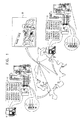
Reference is now made to FIG. 1, which is a schematic illustration of a multi-position object tracing and tracking system constructed and operable in accordance with a preferred embodiment of the present invention.
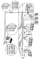
図1に示すように、オブジェクトをトレースし、追跡する、複数の地理的に異なる位置を対象とするトレースおよび追跡システムが好適に提供される。倉庫のような典型的なこのような位置で、積み重ね、折りたたまれたコンテナ10のような複数のオブジェクトにはそれぞれに画像化可能識別子12が付いている。画像化可能識別子は、好ましくはマルチセグメントの色符号化されたディスク形式であり、様々なセグメントが様々な色を有するマルチセグメントの多色識別子を含むことが好ましい。好ましい画像化可能識別子は、One Penn Plaza、Suite 2210、New York、NY、U.S.A.のImageID Inc.からImagecodeの商品名で市販されている。この識別子は、参照により本明細書にその開示を組み込んだ次の参照文献で説明されている。
As shown in FIG. 1, a tracing and tracking system for a plurality of geographically different locations that trace and track objects is preferably provided. In a typical such location, such as a warehouse, each of a plurality of objects such as stacked and collapsed
米国特許第09/508,300号
公開されたPCT特許出願WO 00/04711
デジタルカメラのような従来型イメージャ14により複数のオブジェクト上の画像化可能識別子を一緒に単一写真内に撮像することができることが本発明の特徴である。これは、原則として、様々な色が、空間的にも色空間でも相互に比較的容易に区別される2次元空間における画像化可能識別子に表示されるということによるものである。
It is a feature of the present invention that an imageable identifier on multiple objects can be imaged together in a single photograph by a conventional imager 14 such as a digital camera. This is due to the fact that, in principle, various colors are displayed in imageable identifiers in a two-dimensional space that are relatively easily distinguished from each other both in space and in color space.
イメージャの画像出力は、局所的に画像出力を処理し、所与の画像または一連の画像で画像化される画像化可能識別子のすべてに対応する複数の数値または英数字の識別子を表す出力指示18を提供することができるコンピュータ16に提供されることが好ましい。別法として、または追加として、コンピュータ16は、インターネットのような任意の適切なコンピュータネットワークを介して遠隔追跡センター20と通信することができ、遠隔追跡センター20は、処理用画像出力を受信することができるか、または所与の画像または一連の画像で画像化される画像化可能識別子のすべてに対応する複数の数値または英数字識別子を受信することができる。画像出力は、将来取り出すためにコンピュータ16に局所的に、または遠隔追跡センター20に記憶することもできる。
The imager's image output processes the image output locally and
遠隔追跡センター20は、好ましくは、それによって識別されるオブジェクトの容易な計数、追跡、および位置特定を可能にするために、複数の地理的に異なる位置からの追跡された数値または英数字識別子の記録を蓄積する。遠隔追跡センター20は、様々な地理的に異なる位置から受信した通信に基づいて更新されたデータベースを好適に維持する。
The
次に、本発明の別の好ましい実施形態により構築され、動作可能な複数の位置のオブジェクトのトレースおよび追跡システムの略図である図2を参照する。図2に示すように、オブジェクトをトレースし、追跡するために探される複数の地理的に異なる位置を対象とするトレースおよび追跡システムが好適に提供される。倉庫のような典型的なこのような位置で、複数の積み重ねられたコンテナ30または棚に格納されたオブジェクトのような複数のオブジェクトにはそれぞれ画像化可能識別子32が付いている。画像化可能識別子は、好ましくはマルチセグメントの色符号化されたディスク形式であり、様々なセグメントが様々な色を有することがマルチセグメントの多色識別子を含むことが好ましい。好ましい画像化可能識別子は、One Penn Plaza、Suite 2210、New York、NY、U.S.A.のImageID Inc.からImagecodeの商品名で市販されている。この識別子は、参照により本明細書にその開示を組み込んだ次の参照文献で説明されている。
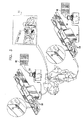
Reference is now made to FIG. 2, which is a schematic illustration of a multi-position object tracing and tracking system constructed and operable in accordance with another preferred embodiment of the present invention. As shown in FIG. 2, a tracing and tracking system is preferably provided that targets multiple geographically different locations sought to trace and track an object. In a typical such location, such as a warehouse, each of a plurality of objects, such as a plurality of stacked
米国特許第09/508,300号
公開されたPCT特許出願WO 00/04711
パノラマデジタルカメラのような従来型イメージャ34により複数のオブジェクト上の画像化可能識別子を一緒に単一の写真内または一連の写真内に自動的に撮像することができることが本発明の具体的な機能である。これは、原則として、様々な色が、空間的にも色空間でも相互に比較的容易に区別される2次元空間における画像化可能識別子に表示されるということによるものである。
Specific features of the present invention that a
図2の構成は、各オブジェクトまたは積み重ねられたオブジェクトに接近すること、またはオブジェクトを、追跡局を通過させることを必要とせずに、多数のオブジェクトの在庫記録を自動的に連続して更新するために特に有用である。 The arrangement of FIG. 2 automatically and continuously updates the inventory records of multiple objects without having to approach each object or stacked object or pass the object through a tracking station. Is particularly useful.
イメージャの画像出力は、局所的に画像出力を処理し、所与の画像または一連の画像で画像化される画像化可能識別子のすべてに対応する複数の数値または英数字の識別子を表す出力指示38を提供することができるコンピュータ36に提供されることが好ましい。別法として、または追加として、コンピュータ36は、インターネットのような任意の適切なコンピュータネットワークを介して遠隔追跡センター40と通信することができ、遠隔追跡センター40は、処理用画像出力を受信することができるか、または所与の画像または一連の画像で画像化される画像化可能識別子のすべてに対応する複数の数値または英数字識別子を受信することができる。画像出力は、将来取り出すためにコンピュータ36に局所的に、または遠隔追跡センター40に記憶することもできる。
The imager's image output processes the image output locally and an
遠隔追跡センター40は、好ましくは、それによって識別されるオブジェクトの容易な計数、追跡、および位置特定を可能にするために、複数の地理的に異なる位置からの追跡された数値または英数字識別子の記録を蓄積する。遠隔追跡センター40は、様々な地理的に異なる位置から受信した通信に基づいて更新されたデータベースを好適に維持する。
The
次に、本発明のさらに別の好ましい実施形態により構築され、動作可能な複数位置のオブジェクトのトレースおよび追跡システムの略図である図3を参照する。図3に示すように、オブジェクトをトレースし、追跡するために探される複数の地理的に異なる位置を対象とするトレースおよび追跡システムが好適に提供される。倉庫のような典型的なこのような位置で、複数のコンテナ50のような複数のオブジェクトにはそれぞれ画像化可能識別子52が付いている。各画像化可能識別子は、好ましくはマルチセグメントの色符号化されたディスク形式であり、様々なセグメントが様々な色を有することが好ましいマルチセグメントの多色識別子を含むことが好ましい。好ましい画像化可能識別子は、One Penn Plaza、Suite 2210、New York、NY、U.S.A.のImageID Inc.からImagecodeの商品名で市販されている。この識別子は、参照により本明細書にその開示を組み込んだ次の参照文献で説明されている。
Reference is now made to FIG. 3, which is a schematic illustration of a multi-position object tracing and tracking system constructed and operable in accordance with yet another preferred embodiment of the present invention. As shown in FIG. 3, a tracing and tracking system is preferably provided that targets multiple geographically different locations sought to trace and track an object. In a typical such location, such as a warehouse, a plurality of objects, such as a plurality of
米国特許第09/508,300号
公開されたPCT特許出願WO 00/04711
デジタルカメラのような従来型イメージャ54により1つまたは複数のオブジェクト上の複数の画像化可能識別子を一緒に単一の写真内または一連の写真内に自動的に撮像することができることが本発明の特徴である。これは、原則として、様々な色が、空間的にも色空間でも相互に比較的容易に区別される2次元空間における画像化可能識別子に表示されるということによるものである。
It is a feature of the present invention that a
図3の構成は、比較的多数の使用可能な数値または英数字識別子を提供するために特に有用である。例えば、単一のImagecode(商標)画像化可能識別子は、通常、約60,000の組み合わせを提供する。2つのImagecode(商標)画像化可能識別子を所定の相対空間のオリエンテーションで使用することにより、約60,000×60,000の組み合わせを提供することができる。 The configuration of FIG. 3 is particularly useful for providing a relatively large number of usable numeric or alphanumeric identifiers. For example, a single Imagecode ™ imageable identifier typically provides about 60,000 combinations. By using two Imagecode ™ imageable identifiers in a given relative space orientation, a combination of about 60,000 × 60,000 can be provided.
イメージャの画像出力は、局所的に画像出力を処理し、所与の画像または一連の画像で画像化される複数の画像化可能識別子のすべてに対応する複数の数値または英数字の識別子を表す出力指示58を提供することができるコンピュータ56に提供されることが好ましい。別法として、または追加として、コンピュータ56は、インターネットのような任意の適切なコンピュータネットワークを介して遠隔追跡センター60と通信することができ、遠隔追跡センター60は、処理用画像出力を受信することができるか、または所与の画像または一連の画像で画像化される画像化可能識別子のすべてに対応する複数の数値または英数字識別子を受信することができる。画像出力は、将来取り出すためにコンピュータ56に局所的に、または遠隔追跡センター60に記憶することもできる。
The imager's image output processes the image output locally and outputs representing multiple numeric or alphanumeric identifiers corresponding to all of the multiple imageable identifiers imaged in a given image or series of images. Preferably, it is provided to a
遠隔追跡センター60は、好ましくは、それによって識別されるオブジェクトの容易な計数、追跡、および位置特定を可能にするために、複数の地理的に異なる位置からの追跡された数値または英数字識別子の記録を蓄積する。遠隔追跡センター60は、様々な地理的に異なる位置から受信した通信に基づいて更新されたデータベースを好適に維持する。 The remote tracking center 60 preferably provides for tracked numeric or alphanumeric identifiers from multiple geographically different locations to allow easy counting, tracking, and locating of objects identified thereby. Accumulate records. Remote tracking center 60 preferably maintains an updated database based on communications received from various geographically different locations.
本発明の好ましい実施形態によれば、マルチセグメントの多色識別子12、32、および52は、少なくとも
複数のオブジェクト=(n×(n−1)(p-2)×(n−2))/p
に粗等しい複数のオブジェクトを識別し、区別することができる。ここで、nは異なる色の数であり、pはセグメント数である。
According to a preferred embodiment of the present invention, the multi-segment
Objects that are roughly equal to can be identified and distinguished. Here, n is the number of different colors, and p is the number of segments.
上記の計算は、画像化可能識別子のいかなる所定のオリエンテーション(orientation)をも仮定しない。
より具体的には、マルチセグメントの多色識別子は、少なくとも
複数のオブジェクト=n×(n―1)(p-2)×(n−2)
に粗等しい複数のオブジェクトを識別し、区別することができる。ここで、nは異なる色の数であり、pはセグメント数である。
The above calculations do not assume any predetermined orientation of the imageable identifier.
More specifically, the multi-segment multicolor identifier includes at least a plurality of objects = n × (n−1) (p−2) × (n−2).
Objects that are roughly equal to can be identified and distinguished. Here, n is the number of different colors, and p is the number of segments.
この計算は、画像化可能識別子の周知または一定のオリエンテーションを仮定する。
本発明の好ましい実施形態によれば、マルチセグメントの多色識別子は固有のオリエンテーションを有する。これは、この通りである必要はないということを理解されたい。マルチセグメントの多色識別子が固有のオリエンテーションを持たない場合、図4に例示した方法は特に有用である。
This calculation assumes a known or constant orientation of the imageable identifier.
According to a preferred embodiment of the present invention, the multi-segment multicolor identifier has a unique orientation. It should be understood that this need not be the case. The method illustrated in FIG. 4 is particularly useful when the multi-segment multicolor identifier does not have a unique orientation.
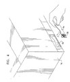
次に、画像化可能識別子のオブジェクトへの正しい貼付方法を示す図である図4を参照する。Imegecode(商標)画像化可能識別子が円対称性であるので、オブジェクトの誤認を避けながら、数値または英数字識別子の使用可能な組み合わせ数を最大限にするには貼付のオリエンテーションが一貫していることが重要であると理解されよう。 Reference is now made to FIG. 4, which is a diagram illustrating a method for correctly attaching an imageable identifier to an object. Because the Imagecode ™ imageable identifier is circularly symmetric, the orientation of the stickers must be consistent to maximize the number of possible combinations of numeric or alphanumeric identifiers while avoiding object misidentification Will be understood as important.
貼付のオリエンテーションが正しくなることを確実にする1つの技術は、3次元的に規定された貼付位置72をコンテナ70上に成型し、または他の方法で成形し、他方、例えば切り込みの入ったような構成になった、コンテナに対して一意のオリエンテーションでしか該3次元的に規定された貼付位置72に入れることができない、裏が粘着性になったステッカーのような画像化可能識別子キャリア74を提供することである。明らかに、図4に示す構造および方法は、複数の画像化可能識別子と単一の画像化可能識別子76が付いた画像化可能識別子キャリア74に適用することができる。画像化可能識別子をオブジェクトに直接印刷または成型するなど、一意のオリエンテーション貼付の他の適切な技術を利用することができることが理解されよう。
One technique for ensuring correct application orientation is to form a three-dimensionally defined application location 72 on the
明瞭化のために、図1、2、3、および4の機能を個別に説明したことに留意されたい。図1、2、3、および4の機能のどれ1つでも、またはそのすべてでも、所与のシステムまたは方法に有利に組み合わせることができることを理解されたい。 Note that for clarity, the functions of FIGS. 1, 2, 3, and 4 have been described separately. It should be understood that any one or all of the functions of FIGS. 1, 2, 3, and 4 can be advantageously combined in a given system or method.
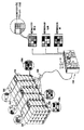
次に、本発明の別の好ましい実施形態により構築され、動作可能なマルチパラメータオブジェクト追跡システムおよび方法の簡略化した絵図である図5を参照する。図5に示すように、様々な商品のクレート(crate)のようなオブジェクトはそれぞれに光感知識別インジケータ100を付けているが、これは多色領域を含み、一意のコードに対応する一意のパターンを規定することが好ましい。オブジェクトは、トラックに積載されたまま、倉庫に格納されたまま、貨車で輸送しているまま、航空機への積載待機中、または船舶への積載待機中など、様々な場所でその位置のまま画像化される。画像化は、カラーCCDカメラのような従来の比較的低価格のカメラ102によって行うことができる。
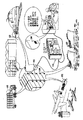
Reference is now made to FIG. 5, which is a simplified pictorial illustration of a multi-parameter object tracking system and method constructed and operable in accordance with another preferred embodiment of the present invention. As shown in FIG. 5, objects, such as various product crate, each have a light
本発明の好ましい一実施形態によれば、識別インジケータ100は、参照によりその開示を本明細書に組み込んだ譲受人の公開されたPCT出願WO 00/04711に図示し、説明されているような静的インジケータである。別法として、または追加として、識別インジケータ100は、図8A〜10を参照して以下で説明するような動的インジケータである。
In accordance with a preferred embodiment of the present invention, the
カメラ102または複数のカメラ102の出力は、各光感知識別インジケータ上の有色領域の組み合わせに対応するコードを抽出するために、その出力が提供する画像を分析するコンピュータ104に適用されることが好ましい。以下で詳細に説明するように、このコードは、オブジェクト識別情報とオブジェクトに関する様々な追加パラメータに関する情報を含むことができる。識別インジケータを復号化する方法の好ましい一実施形態を図11に関して以下で説明する。
The output of the
好ましくは、図5に示すように、識別インジケータ100は、それらが特定するオブジェクトと共に撮像または撮影され、これにより識別インジケータ100に符号化された情報の視覚検証が可能になる。図5に示した実施形態では、識別インジケータ100は、オブジェクトを識別するだけでなく、それ自体の現在の内容、それが曝された最高温度と最高湿度、およびそれが落下したか否かも示す。
Preferably, as shown in FIG. 5, the
識別インジケータ100を生成するために適切な装置(図示せず)は、マルチパラメータオブジェクト追跡システムの一部として提供されることが好ましいということが理解されよう。本発明の一実施形態によれば、静的識別インジケータ100は、符号化ソフトウェアを装備した任意の適切な印刷装置によって生成することができる。これで、オペレータは、使用可能なパラメータのメニュなどから使えるパラメータを選択するか、またはいかなる他の適切な方法によっても符号化された識別インジケータを印刷することができる。別の好ましい実施形態では、動的識別インジケータ100は、図10を参照して以下で説明するように生成することができる。
It will be appreciated that a suitable device (not shown) for generating the
さらに、識別インジケータ100を電子商品監視(EAS)機器または無線周波認識機器(RFID)と共に使用することができる。この実施形態では、視覚感知識別インジケータ100は、その品目がEASまたはRFID機器を有するという指示を含んでおり、その機器のタイプも示すことができることが好ましい。資産の流れを制御するために識別インジケータとEAS/RFID機器のこのような組み合わせを使用することもできる。この場合、EAS機器は、ある品目がある場所を離れることを示すが、このためには、オペレータがカメラ102のようなカメラを利用して視覚感知識別インジケータ100を撮像することが必要となる。適切なEASおよびRFID機器は、HID社、9292 Jeronimo Road,Irvine,CA 92618 USAまたはSensormatic、6600 Congress Ave.,P.O.Box310700,Boca Ration,Florida 33431−0700 USAで製造されている。
Further, the
次に、図5のシステムに含まれることが好ましい4つの機能の簡略化した絵図である図6A、6B、6C、および6Dを参照する。図6Aは、それぞれが共通コンピュータ202にイメージによる出力を提供するCCDカメラのような複数の固定位置イメージャ200を示す。共通コンピュータ202は、イメージャ200から出力されたイメージを分析し、識別インジケータを抽出復号化し、符号化された指示出力をイメージャ200が捕捉した画像と共に遠隔コンピュータ204に提供する。
Reference is now made to FIGS. 6A, 6B, 6C, and 6D, which are simplified pictorial diagrams of four functions that are preferably included in the system of FIG. FIG. 6A shows a plurality of fixed
図6Bは、所与の領域をスキャンして別の時点で別のオブジェクトの画像を提供するための様々なオリエンテーションイメージャ210の使用を示す。図6Aの実施形態のように、共通コンピュータ212は、イメージャ210からの画像出力を分析し、識別インジケータを抽出して復号化し、符号化された識別出力をイメージャ210が捕捉した画像と共に遠隔コンピュータ214に提供する。
FIG. 6B illustrates the use of
図6Cは、異なるレベルの照明下のオブジェクトの画像を提供するための、比較的高い照明環境と低い照明環境で様々なオリエンテーションイメージャ220と222の使用を示す。図6Aおよび6Bの実施形態のように、共通コンピュータ224は、イメージャ220と222から出力されたイメージを分析し、照明に対してその画像を正規化し、識別インジケータを抽出して復号化し、符号化された識別出力をイメージャ220と222が捕捉した画像と共に遠隔コンピュータ226に提供する。
FIG. 6C illustrates the use of
図6Dは、オブジェクトの画像を提供するためのイメージャ230、232、および234の使用を示す。図6A〜6Cの実施形態のように、共通コンピュータ236は、イメージャ230〜234から出力された画像を分析し、本明細書では参照番号238で示した破損した識別インジケータから消失した情報を、1つまたは複数の数学的誤り訂正アルゴリズムを使用して埋め、識別インジケータを抽出して復号化し、符号化された識別出力をイメージャ230〜234が捕捉した訂正されたイメージと共に遠隔コンピュータ240に提供する。BCH符号化またはリードソロモン符号のような適切な数学的誤り訂正アルゴリズムが当技術分野では良く知られており、F.J.MacwilliamsおよびN.Sloaneによる「The Theory of Error−correcting Codes」1977年、North−Holland Publishersに説明されている。
FIG. 6D illustrates the use of
次に、図5のシステムおよび方法で有用な、本明細書ではT型の位置およびオリエンテーション探査装置302を含む識別インジケータ300の簡略化した図である図7を参照する。識別インジケータ300は、本明細書では72個ある比較的多数の有色ピクセルを含むパターンを有する。
Reference is now made to FIG. 7, which is a simplified illustration of an
次に、図5のシステムおよび方法で有用な、液晶ディスプレイのような動的電子ディスプレイで実施される識別インジケータの簡略化した図である図8Aと8Bを参照する。図8Aと8Bの実施形態の識別インジケータ400は、動的であり、変更するパラメータの視覚感知出力指示を提供するために時間と共に変更可能な点で、図7に示すインジケータと区別される。図8Aと8Bを比較することにより、識別インジケータ400が経時的に異なる解像度と識別インジケータの異なる構成を、異なるパラメータの指示と共に提供できることが理解されよう。
Reference is now made to FIGS. 8A and 8B, which are simplified illustrations of identification indicators implemented in a dynamic electronic display, such as a liquid crystal display, useful in the system and method of FIG. The
次に、サブピクセル解像度を有する識別インジケータの図5のシステムおよび方法における使用の略図である図9を参照する。図9に示すように、イメージャ500はそれぞれが情報インジケータ504を付けている複数のオブジェクト502を撮像する。イメージャ500の画像出力は、異なる解像度でコンピュータ506によって分析することができる。第1の解像度では、第1のレベルの情報、この場合はクレートの識別とその内容の一般的な分類を提供することができる。第2の解像度では、追加レベルの情報、例えば梱包された具体的な製品とその重量などを識別インジケータから得ることができる。
Reference is now made to FIG. 9, which is a schematic illustration of the use of an identification indicator having sub-pixel resolution in the system and method of FIG. As shown in FIG. 9, the
次に、動的視覚感知マルチパラメータ識別インジケータの図5のシステムおよび方法における使用の略図である図10を参照する。図10に示すように、人工衛星604からの伝送の受信に基づいて位置を感知するGPSセンサのような位置センサ602、温度センサ606、湿度センサ608、および慣性センサ610を含み、これらすべてがプロセッサ612に出力することが好ましく、プロセッサ612は様々なパラメータの極値を記憶してそれらをLCDディスプレイ614のような動的識別インジケータに適切に符号化された形式で表示することが好ましいマルチパラメータセンサアセンブリ600を提供することができる。センサ602、606、608、および610は、視覚感知出力を生成する必要はない。これは、これらのセンサから受信した入力に基づいてプロセッサ612が視覚感知出力を生成するからである。マルチパラメータセンサアセンブリ600は、LCDディスプレイ614の撮像領域内に配置された視覚感知出力センサ616、またはマルチパラメータセンサアセンブリ600の撮像領域内に配置された視覚感知センサ618のような、視覚感知出力を生成し、プロセッサ612に接続してもしなくてもよい追加センサも含むことができる。
Reference is now made to FIG. 10, which is a schematic illustration of the use of the dynamic visual sensing multi-parameter identification indicator in the system and method of FIG. As shown in FIG. 10, a
プロセッサ612は、LCDディスプレイ614の一部としても符号化される有線入力装置または無線入力装置など、任意の適切な方法によって追加の入力パラメータを受信するよう動作可能でもあることが好ましいことが理解されよう。
It will be appreciated that the processor 612 is preferably also operable to receive additional input parameters by any suitable method, such as a wired input device or a wireless input device that is also encoded as part of the
視覚感知出力センサ616と618は、限定はしないが以下の環境センサを含むことができる。
Switched On I&T Services of Braeside,Victoria,Australiaから市販されているTILTWATCH傾斜インジケータおよびSHOCKWATCHショックインジケータ
Sud−Chemie Performance Packaging−the Americas Rio Grande Industrial Park 101 Christine Drive,Beten,NM 87002 USAから市販されているHumidity Indicator CardsおよびPlugs
IntroTech BV,P.O.Box3,NL−7370 AA Loenen,the Netherlandsから市販されているCOLDMARKおよびWARMMARK温度履歴インジケータ。
Visual
Switched On I & T Services of Braeside, Victoria, TILTWATCH inclination indicator and SHOCKWATCH shock indicators commercially available from Australia Sud-Chemie Performance Packaging-the Americas Rio Grande Industrial Park 101 Christine Drive, Beten, Humidity commercially available from NM 87002 USA Indicator Cards and Plugs
IntroTech BV, P.M. O. Box 3, NL-7370 A COLORMARK and WARMMARK temperature history indicator commercially available from AA Loenen, the Netherlands.
センサ602、606、608、および610は、上記リストから選択しても、または任意の他の適切なセンサであってもよいということが理解されよう。
プロセッサ612はリアルタイムでLCDディスプレイ614を変更するよう動作可能であることが好ましいが、プロセッサ612は、その代わりに、必ずしもリアルタイムであることを必要とせず、定期的にLCDディスプレイ614を変更するよう動作可能とすることができることが理解されよう。
It will be appreciated that the
Although processor 612 is preferably operable to change
次に、図5のシステムの好ましい動作モードを示す簡略化した流れ図である図11を参照する。図11に示すように、通常、それぞれに識別インジケータが付いている複数のオブジェクトを含むオブジェクトの画像が、好ましくはカラーCCDカメラのような従来型カメラによって捕捉される。好ましくは、識別インジケータは、視覚感知識別情報を含む。さらに、識別インジケータは動的インジケータであってよく、温度、湿度、傾斜、および重力加速度のようなオブジェクトに関する様々な追加パラメータに関する指示を提供することができる。他のタイプのパラメータに関する視覚指示も提供することができる。 Reference is now made to FIG. 11, which is a simplified flow diagram illustrating the preferred mode of operation of the system of FIG. As shown in FIG. 11, typically an image of an object comprising a plurality of objects each with an identification indicator is captured, preferably by a conventional camera such as a color CCD camera. Preferably, the identification indicator includes visually sensitive identification information. Further, the identification indicator can be a dynamic indicator and can provide instructions regarding various additional parameters for the object such as temperature, humidity, tilt, and gravitational acceleration. Visual indications regarding other types of parameters can also be provided.
1つまたは複数のカメラからのカメラ出力が、無線で、または有線ネットワークを介して中央画像プロセッサに送信され、中央画像プロセッサは、識別とパラメータデータを抽出するために識別インジケータを位置特定して復号化するようそのままの位置で画像を処理する。識別インジケータだけでなくオブジェクトも示すこのデータを、好ましくは元の画像と共に、画像と復号化されたデータにディスプレイを提供する1つまたは複数のモニタに送信することができる。 Camera output from one or more cameras is transmitted wirelessly or via a wired network to a central image processor that locates and decodes the identification indicator to extract identification and parameter data The image is processed as it is. This data indicating the object as well as the identification indicator can be transmitted, preferably with the original image, to one or more monitors that provide a display for the image and the decoded data.
本発明のシステムおよび方法により、モニタおよび画像プロセッサから遠隔にあってよいオブジェクトと複数の位置をリアルタイムまたは非リアルタイムで監視することが可能になることが理解されよう。 It will be appreciated that the systems and methods of the present invention allow real-time or non-real-time monitoring of objects and multiple locations that may be remote from the monitor and image processor.
本発明は上記で具体的に説明したものに限定されないことが当業者には理解されよう。そうではなく、本発明の範囲は、上記に説明した様々な実施形態の組み合わせおよび副結合の両方と、上記説明を読めば当業者には当然想起され、従来技術には含まれない上記実施形態の修正形態および追加を含む。 Those skilled in the art will appreciate that the present invention is not limited to what has been specifically described above. Rather, the scope of the present invention will be conceived by those skilled in the art upon reading both the combination and subcombination of the various embodiments described above and the above embodiments not included in the prior art. Including modifications and additions.
Claims (86)
追跡されるべき複数のオブジェクトのそれぞれに少なくとも1つの画像化可能識別子を貼付するステップと、
前記少なくとも1つの画像化可能識別子を含む、前記複数のオブジェクトの少なくとも1つのオブジェクトの少なくとも一部の画像を提供するために周知の位置で前記複数のオブジェクトの前記少なくとも1つのオブジェクトの少なくとも一部を撮像するステップと、
前記少なくとも1つの画像化可能識別子を含む前記オブジェクトの前記少なくとも一部の画像を利用して前記複数のオブジェクトの前記少なくとも1つのオブジェクトの前記位置の出力指示を提供するステップと
を含むオブジェクト追跡方法。 In the object tracking method,
Affixing at least one imageable identifier to each of the plurality of objects to be tracked;
At least a portion of the at least one object of the plurality of objects at a known location to provide an image of at least a portion of the at least one object of the plurality of objects including the at least one imageable identifier. Imaging step;
Providing an output indication of the position of the at least one object of the plurality of objects using the at least part of the image of the object including the at least one imageable identifier.
複数のオブジェクト=(n×(n−1)(p-2)×(n−2))/p
に粗等しい複数のオブジェクトを識別し、区別することができ、
nは異なる色の数であり、
pはセグメント数である請求項7に記載の方法。 The multi-segment multicolor identifier includes at least a plurality of objects = (n × (n−1) (p-2) × (n−2)) / p.
Can identify and distinguish between multiple objects roughly equal to
n is the number of different colors,
The method of claim 7, wherein p is the number of segments.
複数のオブジェクト=n×(n―1)(p-2)×(n−2)
に粗等しい複数のオブジェクトを識別し、区別することができ、
nは異なる色の数であり、
pはセグメント数である請求項7に記載の方法。 The multi-segment multi-color identifier is at least a plurality of objects = n × (n−1) (p-2) × (n-2)
Can identify and distinguish between multiple objects roughly equal to
n is the number of different colors,
The method of claim 7, wherein p is the number of segments.
複数のオブジェクト=(n×(n−1)(p-2)×(n−2))/p
に粗等しい複数のオブジェクトを識別し、区別することができ、
nは異なる色の数であり、
pはセグメント数である請求項1に記載の方法。 The identifier is at least a plurality of objects = (n × (n−1) (p-2) × (n−2)) / p
Can identify and distinguish between multiple objects roughly equal to
n is the number of different colors,
The method of claim 1, wherein p is the number of segments.
複数のオブジェクト=n×(n―1)(p-2)×(n−2)
に粗等しい複数のオブジェクトを識別し、区別することができ、
nは異なる色の数であり、
pはセグメント数である請求項1に記載の方法。 The multi-segment multi-color identifier is at least a plurality of objects = n × (n−1) (p-2) × (n-2)
Can identify and distinguish between multiple objects roughly equal to
n is the number of different colors,
The method of claim 1, wherein p is the number of segments.
追跡されるべき複数のオブジェクトのそれぞれに貼付された少なくとも1つの画像化可能識別子と、
前記少なくとも1つの画像化可能識別子を含む、前記複数のオブジェクトの少なくとも1つのオブジェクトの少なくとも一部の画像を提供するために周知の位置で前記複数のオブジェクトの前記少なくとも1つのオブジェクトの少なくとも一部を撮像するイメージャと、
前記少なくとも1つの画像化可能識別子を含む前記オブジェクトの前記少なくとも一部の画像を利用して前記複数のオブジェクトの前記少なくとも1つのオブジェクトの前記位置の出力指示を提供するプロセッサと
を含むオブジェクト追跡システム。 In the object tracking system,
At least one imageable identifier affixed to each of the plurality of objects to be tracked;
At least a portion of the at least one object of the plurality of objects at a known location to provide an image of at least a portion of the at least one object of the plurality of objects including the at least one imageable identifier. An imager to image,
A processor for providing an output indication of the position of the at least one object of the plurality of objects using the at least part of the image of the object including the at least one imageable identifier.
複数のオブジェクト=(n×(n−1)(p-2)×(n−2))/p
に粗等しい複数のオブジェクトを識別し、区別することができ、
nは異なる色の数であり、
pはセグメント数である請求項27に記載のオブジェクト追跡システム。 The multi-segment multicolor identifier includes at least a plurality of objects = (n × (n−1) (p-2) × (n−2)) / p.
Can identify and distinguish between multiple objects roughly equal to
n is the number of different colors,
28. The object tracking system of claim 27, wherein p is the number of segments.
複数のオブジェクト=n×(n―1)(p-2)×(n−2)
に粗等しい複数のオブジェクトを識別し、区別することができ、
nは異なる色の数であり、
pはセグメント数である請求項27に記載のオブジェクト追跡システム。 The multi-segment multi-color identifier is at least a plurality of objects = n × (n−1) (p-2) × (n-2)
Can identify and distinguish between multiple objects roughly equal to
n is the number of different colors,
28. The object tracking system of claim 27, wherein p is the number of segments.
複数のオブジェクト=(n×(n−1)(p-2)×(n−2))/p
に粗等しい複数のオブジェクトを識別し、区別することができ、
nは異なる色の数であり、
pはセグメント数である請求項21に記載のオブジェクト追跡システム。 The identifier is at least a plurality of objects = (n × (n−1) (p-2) × (n−2)) / p
Can identify and distinguish between multiple objects roughly equal to
n is the number of different colors,
The object tracking system of claim 21, wherein p is the number of segments.
複数のオブジェクト=n×(n―1)(p-2)×(n−2)
に粗等しい複数のオブジェクトを識別し、区別することができ、
nは異なる色の数であり、
pはセグメント数である請求項21に記載のオブジェクト追跡システム。 The multi-segment multi-color identifier is at least a plurality of objects = n × (n−1) (p-2) × (n-2)
Can identify and distinguish between multiple objects roughly equal to
n is the number of different colors,
The object tracking system of claim 21, wherein p is the number of segments.
追跡中のオブジェクト上の視覚感知インジケータと、
前記視覚感知インジケータも示す前記追跡中のオブジェクトの画像を捕捉する少なくとも1つのイメージャと、
前記少なくとも1つのイメージャの出力を受信して前記出力から前記視覚感知インジケータが示す符号化された情報を抽出する少なくとも1つの画像プロセッサと
を含むオブジェクト追跡システム。 In the object tracking system,
A visual sensing indicator on the object being tracked;
At least one imager that captures an image of the object being tracked that also exhibits the visual sensing indicator;
An object tracking system comprising: at least one image processor that receives the output of the at least one imager and extracts encoded information indicated by the visual sensing indicator from the output.
視覚感知インジケータを追跡中のオブジェクトに関連付けるステップと、
前記視覚感知インジケータも示す追跡中の前記オブジェクトの画像を捕捉するステップと、
前記少なくとも1つのイメージャの画像処理出力と、前記出力から前記視覚感知インジケータが示す符号化された情報を抽出するステップと
を含むオブジェクト追跡方法。 In the object tracking method,
Associating a visual indicator with the object being tracked;
Capturing an image of the object being tracked that also shows the visual sensing indicator;
An object tracking method comprising: image processing output of the at least one imager; and extracting encoded information indicated by the visual sensing indicator from the output.
監視中のオブジェクトに関連付けられた複数のセンサと、
前記複数のセンサのセンサ出力を受信して、前記センサ出力の視覚感知指示を提供する、前記オブジェクトのそれぞれに関連付けられた視覚感知インジケータと、
前記視覚感知インジケータの画像を捕捉する少なくとも1つのイメージャと、
前記少なくとも1つのイメージャの画像出力を受信して、前記画像出力から前記視覚感知インジケータが示す符号化された情報を抽出する少なくとも1つの画像プロセッサと
を含むオブジェクト監視システム。 In the object monitoring system,
Multiple sensors associated with the object being monitored;
A visual sensing indicator associated with each of the objects that receives sensor outputs of the plurality of sensors and provides a visual sensing indication of the sensor outputs;
At least one imager for capturing an image of the visual sensing indicator;
An object monitoring system comprising: at least one image processor that receives an image output of the at least one imager and extracts encoded information indicated by the visual sensing indicator from the image output.
複数のセンサを監視中のオブジェクトに関連付けるステップと、
視覚感知インジケータを前記オブジェクトのそれぞれに関連付けるステップと、
前記複数のセンサのセンサ出力を前記視覚感知インジケータに提供するステップと、
前記センサ出力の視覚感知指示を提供するように前記視覚感知インジケータを操作するステップと、
少なくとも1つのイメージャを利用して前記視覚感知インジケータの画像を捕捉するステップと、
少なくとも1つの画像プロセッサを利用して前記少なくとも1つのイメージャの画像出力を受信して前記画像出力から前記視覚感知インジケータが示す符号化された情報を抽出するステップと
を含むオブジェクト監視方法。 In the object monitoring method,
Associating multiple sensors with the monitored object;
Associating a visual sensing indicator with each of said objects;
Providing sensor outputs of the plurality of sensors to the visual sensing indicator;
Manipulating the visual sensing indicator to provide a visual sensing indication of the sensor output;
Capturing an image of the visual sensing indicator using at least one imager;
Receiving the image output of the at least one imager using at least one image processor and extracting the encoded information indicated by the visual sensing indicator from the image output.
Applications Claiming Priority (2)
| Application Number | Priority Date | Filing Date | Title |
|---|---|---|---|
| US10/052,427 US6801245B2 (en) | 2002-01-18 | 2002-01-18 | Method for automatic identification and data capture |
| PCT/IL2003/000045 WO2003060626A2 (en) | 2002-01-18 | 2003-01-16 | System and methodology for tracking objects using visually sensible indicators |
Publications (2)
| Publication Number | Publication Date |
|---|---|
| JP2005518320A true JP2005518320A (en) | 2005-06-23 |
| JP2005518320A5 JP2005518320A5 (en) | 2005-12-22 |
Family
ID=21977541
Family Applications (1)
| Application Number | Title | Priority Date | Filing Date |
|---|---|---|---|
| JP2003560656A Pending JP2005518320A (en) | 2002-01-18 | 2003-01-16 | System and method for object tracking using a visual sensing indicator |
Country Status (5)
| Country | Link |
|---|---|
| US (4) | US6801245B2 (en) |
| EP (1) | EP1477021A4 (en) |
| JP (1) | JP2005518320A (en) |
| AU (1) | AU2003207962A1 (en) |
| WO (1) | WO2003060626A2 (en) |
Cited By (8)
| Publication number | Priority date | Publication date | Assignee | Title |
|---|---|---|---|---|
| JP2009537038A (en) * | 2006-05-07 | 2009-10-22 | バーコード リミティド | System and method for improving quality control in a product logistic chain |
| JP2010526386A (en) * | 2007-05-06 | 2010-07-29 | バーコード リミティド | Quality control system and method using bar code signs |
| US8807422B2 (en) | 2012-10-22 | 2014-08-19 | Varcode Ltd. | Tamper-proof quality management barcode indicators |
| US9396423B2 (en) | 2008-06-10 | 2016-07-19 | Varcode Ltd. | System and method for quality management utilizing barcode indicators |
| US10445678B2 (en) | 2006-05-07 | 2019-10-15 | Varcode Ltd. | System and method for improved quality management in a product logistic chain |
| US10697837B2 (en) | 2015-07-07 | 2020-06-30 | Varcode Ltd. | Electronic quality indicator |
| US11060924B2 (en) | 2015-05-18 | 2021-07-13 | Varcode Ltd. | Thermochromic ink indicia for activatable quality labels |
| US11704526B2 (en) | 2008-06-10 | 2023-07-18 | Varcode Ltd. | Barcoded indicators for quality management |
Families Citing this family (38)
| Publication number | Priority date | Publication date | Assignee | Title |
|---|---|---|---|---|
| US6943678B2 (en) * | 2000-01-24 | 2005-09-13 | Nextreme, L.L.C. | Thermoformed apparatus having a communications device |
| US6801245B2 (en) * | 2002-01-18 | 2004-10-05 | Imageid Ltd. | Method for automatic identification and data capture |
| US20040153386A1 (en) * | 2002-08-19 | 2004-08-05 | George Eckerdt | Tangible security asset management system and methods thereof |
| US20060288101A1 (en) * | 2003-08-19 | 2006-12-21 | Key Systems, Inc. | Multipurpose Interface and Control System |
| JP2005293020A (en) * | 2004-03-31 | 2005-10-20 | Fujitsu Ltd | Method for searching for video data of moving object, apparatus for imaging/detecting moving object, and apparatus for searching for video data of moving object |
| US7770792B2 (en) * | 2004-06-23 | 2010-08-10 | Sap Ag | Methods and systems for managing stock transportation |
| US7669763B2 (en) * | 2004-06-23 | 2010-03-02 | Sap Ag | Methods and system for managing stock |
| US20060190356A1 (en) * | 2004-12-02 | 2006-08-24 | Yaron Nemet | System and method for quality assurance |
| US20070069028A1 (en) * | 2004-12-10 | 2007-03-29 | Yaron Nemet | System to improve reading performance and accuracy of single or two dimensional data codes in a large field of view |
| US9524485B1 (en) | 2005-01-31 | 2016-12-20 | Amazon Technologies, Inc. | System and method for pattern assignment for pattern-based item identification in a materials handling facility |
| JP4548316B2 (en) * | 2005-02-10 | 2010-09-22 | セイコーエプソン株式会社 | Color ID card, card creation system, card creation method, program, and storage medium |
| US20060210115A1 (en) * | 2005-03-01 | 2006-09-21 | Imageid | System for, method of generating and organizing a warehouse database and using the database to provide and/or present required information |
| JP4605384B2 (en) * | 2005-11-07 | 2011-01-05 | オムロン株式会社 | Portable information processing terminal device |
| US8381982B2 (en) * | 2005-12-03 | 2013-02-26 | Sky-Trax, Inc. | Method and apparatus for managing and controlling manned and automated utility vehicles |
| US8849943B2 (en) | 2005-12-19 | 2014-09-30 | Palo Alto Research Center Incorporated | Using multi-resolution visual codes to facilitate information browsing in the physical world |
| US8159330B2 (en) * | 2007-11-20 | 2012-04-17 | Pitney Bowes Inc. | System and method for dimensional rating using RFID technology |
| US8189919B2 (en) * | 2007-12-27 | 2012-05-29 | Chung Mong Lee | Method and system for container identification |
| US7895131B2 (en) * | 2008-01-04 | 2011-02-22 | Tracking Innovations, Inc. | Cargo tracking apparatus, system and method |
| US7884734B2 (en) * | 2008-01-31 | 2011-02-08 | Microsoft Corporation | Unique identification of devices using color detection |
| US8565913B2 (en) * | 2008-02-01 | 2013-10-22 | Sky-Trax, Inc. | Apparatus and method for asset tracking |
| US8295583B2 (en) * | 2008-07-31 | 2012-10-23 | Metaform Ltd. | System and method for automatic recognition of undetected assets |
| WO2010018464A2 (en) * | 2008-08-12 | 2010-02-18 | Medical Systems Design Pty Ltd. | Methods and systems for tracking objects in a validation process |
| WO2010022026A1 (en) * | 2008-08-18 | 2010-02-25 | Waterloo Industries, Inc. | Systems and arrangements for object identification |
| EP2422294B1 (en) | 2009-04-20 | 2017-04-19 | Metaform Ltd. | A multiple barcode detection system and method |
| US7878140B1 (en) | 2009-04-28 | 2011-02-01 | Hisco, Inc. | Device and method to insure integrity to body armor or other ballistic protection apparatus |
| CN101691196B (en) * | 2009-06-25 | 2011-11-09 | 上海精星仓储设备工程有限公司 | Bar code locating S/R machine |
| EP2643792A4 (en) | 2010-11-18 | 2015-09-02 | Sky Trax Inc | Load tracking utilizing load identifying indicia and spatial discrimination |
| DE102010053081A1 (en) * | 2010-12-01 | 2012-06-06 | Ima Klessmann Gmbh Holzbearbeitungssysteme | Process for processing plate-shaped products |
| US9010653B2 (en) * | 2012-05-03 | 2015-04-21 | Ananya Rajagopal | Erasable barcode |
| US10147025B2 (en) * | 2012-07-17 | 2018-12-04 | Shockwatch, Inc. | Visual indicator status recognition |
| US9811738B2 (en) * | 2012-12-06 | 2017-11-07 | Nec Corporation | Appearance presentation system, method, and program |
| ES2529514B1 (en) * | 2014-09-26 | 2015-07-23 | Ems Pathology Medical Solutions, S.L. | Device and method of traceability of samples for diagnosis and / or medical research |
| CN107111734A (en) * | 2014-12-24 | 2017-08-29 | 开利公司 | Ambient parameter monitor with machine readable display |
| WO2016160912A1 (en) * | 2015-03-30 | 2016-10-06 | Temptime Corporation | A two dimensional barcode with dynamic environmental data system, method, and apparatus |
| US10546172B2 (en) | 2015-03-30 | 2020-01-28 | Temptime Corporation | Two dimensional barcode with dynamic environmental data system, method, and apparatus |
| WO2017006314A1 (en) | 2015-07-05 | 2017-01-12 | THE WHOLLYSEE.Ltd. | Optical identification and characterization system and tagss |
| US9616382B2 (en) | 2015-08-11 | 2017-04-11 | Desiccare, Inc. | Humidity control system |
| US11734539B2 (en) | 2021-04-05 | 2023-08-22 | Temptime Corporation | Dynamic optical property windows in indicia with sensors |
Family Cites Families (62)
| Publication number | Priority date | Publication date | Assignee | Title |
|---|---|---|---|---|
| US3636317A (en) * | 1969-04-28 | 1972-01-18 | Charecogn Systems Inc | Machine readable code track |
| US3646264A (en) * | 1969-09-11 | 1972-02-29 | Us Army | Method of acquiring a moving target |
| US3646624A (en) | 1969-09-24 | 1972-03-07 | Blessings Inc | Disposable drawsheet |
| DE2336246A1 (en) * | 1973-07-17 | 1975-02-06 | Interroll Foerdertechnik Gmbh | ADJUSTABLE CODING REFLECTOR |
| US4044227A (en) | 1975-08-07 | 1977-08-23 | The Upjohn Company | Bar code reader |
| US4268179A (en) | 1979-10-29 | 1981-05-19 | E. I. Du Pont De Nemours And Company | Method and system for reproducing identification characters |
| US4345274A (en) * | 1980-10-08 | 1982-08-17 | Servo Corporation Of America | Object identification system utilizing closed circuit television |
| US5468949A (en) | 1985-02-28 | 1995-11-21 | Symbol Technologies, Inc. | Portable laser diode scanning head |
| US4844509A (en) | 1987-01-21 | 1989-07-04 | Wright Line, Inc. | Coding system |
| US4794238A (en) | 1987-10-09 | 1988-12-27 | Ultracision, Inc. | Method and apparatus for reading and marking a small bar code on a surface of an item |
| US5113349A (en) * | 1988-03-26 | 1992-05-12 | Fuji Electric Co. Ltd. | Method and system for storing/removing and distributing articles of manufacture |
| US4858000A (en) | 1988-09-14 | 1989-08-15 | A. C. Nielsen Company | Image recognition audience measurement system and method |
| US5811785A (en) | 1988-10-21 | 1998-09-22 | Symbol Technologies, Inc. | Scanning system with adjustable light output and/or scanning angle |
| US4924088A (en) * | 1989-02-28 | 1990-05-08 | George Carman | Apparatus for reading information marks |
| US5828049A (en) | 1989-06-06 | 1998-10-27 | Metrologic Instruments Inc. | Code symbol reading system with multi-port digital signal decoder |
| US5153842A (en) * | 1990-02-05 | 1992-10-06 | Pitney Bowes Inc. | Integrated circuit package label and/or manifest system |
| US5988508A (en) | 1990-05-08 | 1999-11-23 | Symbol Technologies, Inc. | Laser scanning system and scanning method for reading 1-D and 2-D barcode symbols |
| US5340971A (en) | 1990-09-17 | 1994-08-23 | Metrologic Instruments, Inc. | Automatic bar code reading system having selectable long range and short range modes of operation |
| US5260553A (en) | 1990-09-17 | 1993-11-09 | Metrologic Instruments, Inc. | Automatic hand-supportable laser bar code symbol scanner and method of reading bar code symbols using the same |
| US6283375B1 (en) | 1990-09-10 | 2001-09-04 | Metrologic Instruments, Inc. | Automatically-activated hand-supportable laser scanning bar code symbol reading system with data transmission activation switch |
| WO1993010506A1 (en) | 1991-11-22 | 1993-05-27 | Engineered Data Products, Inc. | Label generation apparatus |
| US5635403A (en) * | 1991-12-13 | 1997-06-03 | Nuclear Fuel Services, Inc. | Sample containment card for air or station contamination monitoring system and process |
| JP3211526B2 (en) * | 1993-12-21 | 2001-09-25 | 富士通株式会社 | Picking system |
| US5539394A (en) * | 1994-03-16 | 1996-07-23 | International Business Machines Corporation | Time division multiplexed batch mode item identification system |
| US5587906A (en) | 1994-06-13 | 1996-12-24 | Trw Inc. | Method and apparatus for sensing a vehicle crash condition using velocity enhanced acceleration crash metrics |
| US5565858A (en) * | 1994-09-14 | 1996-10-15 | Northrop Grumman Corporation | Electronic inventory system for stacked containers |
| US6032861A (en) * | 1995-01-03 | 2000-03-07 | Lemelson; Jerome H. | Method and apparatus for encoding and decoding bar codes with primary and secondary information and method of using such bar codes |
| US5600121A (en) | 1995-03-20 | 1997-02-04 | Symbol Technologies, Inc. | Optical reader with independent triggering and graphical user interface |
| JP3085468B2 (en) * | 1995-03-27 | 2000-09-11 | ティー・シー・エム株式会社 | Container handling equipment and management system |
| US6075441A (en) | 1996-09-05 | 2000-06-13 | Key-Trak, Inc. | Inventoriable-object control and tracking system |
| US6252508B1 (en) | 1995-10-11 | 2001-06-26 | Motorola, Inc. | Radio frequency identification tag arranged for magnetically storing tag state information |
| US6023530A (en) | 1995-11-13 | 2000-02-08 | Applied Intelligent Systems, Inc. | Vector correlation system for automatically locating patterns in an image |
| US5698833A (en) * | 1996-04-15 | 1997-12-16 | United Parcel Service Of America, Inc. | Omnidirectional barcode locator |
| US5708470A (en) * | 1996-06-10 | 1998-01-13 | Condor Systems, Inc. | Optical monitoring system apparatus |
| US5914477A (en) * | 1996-06-26 | 1999-06-22 | Ncr Corporation | Line focus barcode scanner |
| US20030118216A1 (en) * | 1996-09-04 | 2003-06-26 | Goldberg David A. | Obtaining person-specific images in a public venue |
| WO1998010358A1 (en) | 1996-09-04 | 1998-03-12 | Goldberg David A | Method and system for obtaining person-specific images in a public venue |
| US5963134A (en) * | 1997-07-24 | 1999-10-05 | Checkpoint Systems, Inc. | Inventory system using articles with RFID tags |
| JPH1153465A (en) | 1997-08-08 | 1999-02-26 | Fujitsu Ltd | Bar code reader |
| JP3576356B2 (en) | 1997-08-08 | 2004-10-13 | 富士通株式会社 | Bar code reader, bar code reading method, and computer readable medium |
| AU9692098A (en) | 1997-10-10 | 1999-05-03 | Interval Research Corporation | Methods and systems for providing human/computer interfaces |
| AU1533899A (en) * | 1997-12-06 | 1999-06-28 | Jon Cameron | Thermochromic bar code |
| US6830181B1 (en) * | 1998-02-09 | 2004-12-14 | Intermec Ip Corp. | Combined optical and radio frequency tag reader |
| US5936527A (en) | 1998-02-10 | 1999-08-10 | E-Tag Systems, Inc. | Method and apparatus for locating and tracking documents and other objects |
| US6142375A (en) * | 1998-04-10 | 2000-11-07 | 3M Innovative Properties Company | Apparatus and method for the optical detection of multiple items on a platform |
| AU4646099A (en) | 1998-07-16 | 2000-02-07 | Imageid Ltd. | Image identification and delivery system |
| US6342830B1 (en) | 1998-09-10 | 2002-01-29 | Xerox Corporation | Controlled shielding of electronic tags |
| DE69938929D1 (en) | 1998-09-11 | 2008-07-31 | Motorola Inc | RFID LABELING DEVICE AND METHOD |
| JP2000090264A (en) | 1998-09-11 | 2000-03-31 | Omron Corp | Method and device for collating living body |
| US6088482A (en) * | 1998-10-22 | 2000-07-11 | Symbol Technologies, Inc. | Techniques for reading two dimensional code, including maxicode |
| CA2287286C (en) * | 1998-10-26 | 2009-01-27 | David A. Shaw | Interrogation, monitoring and data exchange using rfid tags |
| US6285342B1 (en) | 1998-10-30 | 2001-09-04 | Intermec Ip Corp. | Radio frequency tag with miniaturized resonant antenna |
| US6286763B1 (en) | 1999-09-21 | 2001-09-11 | Intermac Ip Corp. | Method and apparatus to automatically search data carriers, such as RFID tags and machine-readable symbols |
| US6294997B1 (en) * | 1999-10-04 | 2001-09-25 | Intermec Ip Corp. | RFID tag having timing and environment modules |
| US6259408B1 (en) | 1999-11-19 | 2001-07-10 | Intermec Ip Corp. | RFID transponders with paste antennas and flip-chip attachment |
| US6496806B1 (en) * | 1999-12-16 | 2002-12-17 | Samsys Technologies Inc. | Method and system for tracking clustered items |
| US6600418B2 (en) * | 2000-12-12 | 2003-07-29 | 3M Innovative Properties Company | Object tracking and management system and method using radio-frequency identification tags |
| US6531675B2 (en) * | 2001-01-31 | 2003-03-11 | Unova Ip Corp. | Laser welding method and apparatus |
| US6801245B2 (en) * | 2002-01-18 | 2004-10-05 | Imageid Ltd. | Method for automatic identification and data capture |
| US20030160096A1 (en) * | 2002-02-28 | 2003-08-28 | Nihon Dot. Com, Co., Ltd | System for managing and tracking tax and production-related information |
| US6787108B2 (en) * | 2002-04-02 | 2004-09-07 | Cmc Daymark Corporation | Plural intrinsic expiration initiation application indicators |
| US7573370B2 (en) * | 2002-09-05 | 2009-08-11 | Honeywell International Inc. | Method and device for storing and distributing information in an RFID tag |
-
2002
- 2002-01-18 US US10/052,427 patent/US6801245B2/en not_active Expired - Lifetime
-
2003
- 2003-01-16 EP EP03704966A patent/EP1477021A4/en not_active Withdrawn
- 2003-01-16 JP JP2003560656A patent/JP2005518320A/en active Pending
- 2003-01-16 US US10/501,776 patent/US7262792B2/en not_active Expired - Lifetime
- 2003-01-16 AU AU2003207962A patent/AU2003207962A1/en not_active Abandoned
- 2003-01-16 WO PCT/IL2003/000045 patent/WO2003060626A2/en active Application Filing
-
2004
- 2004-05-20 US US10/849,026 patent/US6922208B2/en not_active Expired - Lifetime
-
2005
- 2005-07-12 US US11/179,814 patent/US7474333B2/en not_active Expired - Fee Related
Cited By (42)
| Publication number | Priority date | Publication date | Assignee | Title |
|---|---|---|---|---|
| US10445678B2 (en) | 2006-05-07 | 2019-10-15 | Varcode Ltd. | System and method for improved quality management in a product logistic chain |
| US9646277B2 (en) | 2006-05-07 | 2017-05-09 | Varcode Ltd. | System and method for improved quality management in a product logistic chain |
| US10037507B2 (en) | 2006-05-07 | 2018-07-31 | Varcode Ltd. | System and method for improved quality management in a product logistic chain |
| JP2014211883A (en) * | 2006-05-07 | 2014-11-13 | バーコード リミティド | System and method for improving quality management in product logistic chain |
| JP2009537038A (en) * | 2006-05-07 | 2009-10-22 | バーコード リミティド | System and method for improving quality control in a product logistic chain |
| US10726375B2 (en) | 2006-05-07 | 2020-07-28 | Varcode Ltd. | System and method for improved quality management in a product logistic chain |
| US10504060B2 (en) | 2007-05-06 | 2019-12-10 | Varcode Ltd. | System and method for quality management utilizing barcode indicators |
| US10176451B2 (en) | 2007-05-06 | 2019-01-08 | Varcode Ltd. | System and method for quality management utilizing barcode indicators |
| JP2010526386A (en) * | 2007-05-06 | 2010-07-29 | バーコード リミティド | Quality control system and method using bar code signs |
| US8950664B2 (en) | 2007-05-06 | 2015-02-10 | Varcode Ltd. | System and method for quality management utilizing barcode indicators |
| US10776752B2 (en) | 2007-05-06 | 2020-09-15 | Varcode Ltd. | System and method for quality management utilizing barcode indicators |
| US10719749B2 (en) | 2007-11-14 | 2020-07-21 | Varcode Ltd. | System and method for quality management utilizing barcode indicators |
| US9836678B2 (en) | 2007-11-14 | 2017-12-05 | Varcode Ltd. | System and method for quality management utilizing barcode indicators |
| US10262251B2 (en) | 2007-11-14 | 2019-04-16 | Varcode Ltd. | System and method for quality management utilizing barcode indicators |
| US10417543B2 (en) | 2008-06-10 | 2019-09-17 | Varcode Ltd. | Barcoded indicators for quality management |
| US9396423B2 (en) | 2008-06-10 | 2016-07-19 | Varcode Ltd. | System and method for quality management utilizing barcode indicators |
| US10049314B2 (en) | 2008-06-10 | 2018-08-14 | Varcode Ltd. | Barcoded indicators for quality management |
| US11704526B2 (en) | 2008-06-10 | 2023-07-18 | Varcode Ltd. | Barcoded indicators for quality management |
| US9996783B2 (en) | 2008-06-10 | 2018-06-12 | Varcode Ltd. | System and method for quality management utilizing barcode indicators |
| US10303992B2 (en) | 2008-06-10 | 2019-05-28 | Varcode Ltd. | System and method for quality management utilizing barcode indicators |
| US11449724B2 (en) | 2008-06-10 | 2022-09-20 | Varcode Ltd. | System and method for quality management utilizing barcode indicators |
| US9710743B2 (en) | 2008-06-10 | 2017-07-18 | Varcode Ltd. | Barcoded indicators for quality management |
| US9646237B2 (en) | 2008-06-10 | 2017-05-09 | Varcode Ltd. | Barcoded indicators for quality management |
| US11341387B2 (en) | 2008-06-10 | 2022-05-24 | Varcode Ltd. | Barcoded indicators for quality management |
| US10572785B2 (en) | 2008-06-10 | 2020-02-25 | Varcode Ltd. | Barcoded indicators for quality management |
| US11238323B2 (en) | 2008-06-10 | 2022-02-01 | Varcode Ltd. | System and method for quality management utilizing barcode indicators |
| US9626610B2 (en) | 2008-06-10 | 2017-04-18 | Varcode Ltd. | System and method for quality management utilizing barcode indicators |
| US10089566B2 (en) | 2008-06-10 | 2018-10-02 | Varcode Ltd. | Barcoded indicators for quality management |
| US10885414B2 (en) | 2008-06-10 | 2021-01-05 | Varcode Ltd. | Barcoded indicators for quality management |
| US10776680B2 (en) | 2008-06-10 | 2020-09-15 | Varcode Ltd. | System and method for quality management utilizing barcode indicators |
| US10789520B2 (en) | 2008-06-10 | 2020-09-29 | Varcode Ltd. | Barcoded indicators for quality management |
| US10839276B2 (en) | 2012-10-22 | 2020-11-17 | Varcode Ltd. | Tamper-proof quality management barcode indicators |
| US8807422B2 (en) | 2012-10-22 | 2014-08-19 | Varcode Ltd. | Tamper-proof quality management barcode indicators |
| US10552719B2 (en) | 2012-10-22 | 2020-02-04 | Varcode Ltd. | Tamper-proof quality management barcode indicators |
| US9965712B2 (en) | 2012-10-22 | 2018-05-08 | Varcode Ltd. | Tamper-proof quality management barcode indicators |
| US10242302B2 (en) | 2012-10-22 | 2019-03-26 | Varcode Ltd. | Tamper-proof quality management barcode indicators |
| US11060924B2 (en) | 2015-05-18 | 2021-07-13 | Varcode Ltd. | Thermochromic ink indicia for activatable quality labels |
| US11781922B2 (en) | 2015-05-18 | 2023-10-10 | Varcode Ltd. | Thermochromic ink indicia for activatable quality labels |
| US11009406B2 (en) | 2015-07-07 | 2021-05-18 | Varcode Ltd. | Electronic quality indicator |
| US10697837B2 (en) | 2015-07-07 | 2020-06-30 | Varcode Ltd. | Electronic quality indicator |
| US11614370B2 (en) | 2015-07-07 | 2023-03-28 | Varcode Ltd. | Electronic quality indicator |
| US11920985B2 (en) | 2015-07-07 | 2024-03-05 | Varcode Ltd. | Electronic quality indicator |
Also Published As
| Publication number | Publication date |
|---|---|
| WO2003060626A3 (en) | 2003-12-31 |
| WO2003060626B1 (en) | 2004-03-25 |
| US20060144939A1 (en) | 2006-07-06 |
| US7474333B2 (en) | 2009-01-06 |
| AU2003207962A1 (en) | 2003-07-30 |
| US20030136833A1 (en) | 2003-07-24 |
| EP1477021A4 (en) | 2008-03-12 |
| EP1477021A2 (en) | 2004-11-17 |
| US20040212501A1 (en) | 2004-10-28 |
| US20050162274A1 (en) | 2005-07-28 |
| US6801245B2 (en) | 2004-10-05 |
| US6922208B2 (en) | 2005-07-26 |
| WO2003060626A2 (en) | 2003-07-24 |
| AU2003207962A8 (en) | 2003-07-30 |
| US7262792B2 (en) | 2007-08-28 |
Similar Documents
| Publication | Publication Date | Title |
|---|---|---|
| JP2005518320A (en) | System and method for object tracking using a visual sensing indicator | |
| JP6441932B2 (en) | Eye level scanner and display pointer tracking | |
| US9165279B2 (en) | System and method for calibration and mapping of real-time location data | |
| US9984354B1 (en) | Camera time synchronization system | |
| US7422147B2 (en) | System and method for detecting fraudulent transactions of items having item-identifying indicia | |
| JP2005518320A5 (en) | ||
| US7802730B2 (en) | Information carrier integrated with an optically readable information symbol | |
| US20060202032A1 (en) | Combination RFID/image reader | |
| US11900653B1 (en) | Mapping items to locations within an environment based on optical recognition of patterns in images | |
| US7513431B2 (en) | Method and system for aiming an RFID reader | |
| CN105930759A (en) | Collect Vehicle Performance With Pdt | |
| CN105122287B (en) | Coded light device, and product information system comprising such a coded light device | |
| US10037510B2 (en) | System and method for calibration and mapping of real-time location data | |
| US10957173B1 (en) | System and method for providing and/or collecting information relating to objects | |
| US8684271B2 (en) | Composite label with history feature | |
| EP3291159B1 (en) | Management system | |
| JP2002304597A (en) | System for recognizing handwritten numeric information entered in container box | |
| US11120267B1 (en) | Camera solution for identification of items in a confined area | |
| US11599737B1 (en) | System for generating tags | |
| JP2009129269A (en) | Information reader and information reading method | |
| WO2022125193A1 (en) | System and method for indicia avoidance in indicia application | |
| KR20090101643A (en) | Object identification system and method | |
| US20080119955A1 (en) | Information confirmation system |
Legal Events
| Date | Code | Title | Description |
|---|---|---|---|
| A621 | Written request for application examination |
Free format text: JAPANESE INTERMEDIATE CODE: A621 Effective date: 20051209 |
|
| A131 | Notification of reasons for refusal |
Free format text: JAPANESE INTERMEDIATE CODE: A131 Effective date: 20070906 |
|
| A601 | Written request for extension of time |
Free format text: JAPANESE INTERMEDIATE CODE: A601 Effective date: 20071205 |
|
| A602 | Written permission of extension of time |
Free format text: JAPANESE INTERMEDIATE CODE: A602 Effective date: 20071212 |
|
| A521 | Request for written amendment filed |
Free format text: JAPANESE INTERMEDIATE CODE: A523 Effective date: 20080306 |
|
| A02 | Decision of refusal |
Free format text: JAPANESE INTERMEDIATE CODE: A02 Effective date: 20080916 |