JP2005517875A - Vibration control using signal detrending - Google Patents
Vibration control using signal detrending Download PDFInfo
- Publication number
- JP2005517875A JP2005517875A JP2003568738A JP2003568738A JP2005517875A JP 2005517875 A JP2005517875 A JP 2005517875A JP 2003568738 A JP2003568738 A JP 2003568738A JP 2003568738 A JP2003568738 A JP 2003568738A JP 2005517875 A JP2005517875 A JP 2005517875A
- Authority
- JP
- Japan
- Prior art keywords
- vibration
- signal
- control
- feedback
- control drive
- Prior art date
- Legal status (The legal status is an assumption and is not a legal conclusion. Google has not performed a legal analysis and makes no representation as to the accuracy of the status listed.)
- Pending
Links
Images


Classifications
-
- G—PHYSICS
- G03—PHOTOGRAPHY; CINEMATOGRAPHY; ANALOGOUS TECHNIQUES USING WAVES OTHER THAN OPTICAL WAVES; ELECTROGRAPHY; HOLOGRAPHY
- G03F—PHOTOMECHANICAL PRODUCTION OF TEXTURED OR PATTERNED SURFACES, e.g. FOR PRINTING, FOR PROCESSING OF SEMICONDUCTOR DEVICES; MATERIALS THEREFOR; ORIGINALS THEREFOR; APPARATUS SPECIALLY ADAPTED THEREFOR
- G03F7/00—Photomechanical, e.g. photolithographic, production of textured or patterned surfaces, e.g. printing surfaces; Materials therefor, e.g. comprising photoresists; Apparatus specially adapted therefor
- G03F7/70—Microphotolithographic exposure; Apparatus therefor
- G03F7/708—Construction of apparatus, e.g. environment aspects, hygiene aspects or materials
- G03F7/70858—Environment aspects, e.g. pressure of beam-path gas, temperature
- G03F7/709—Vibration, e.g. vibration detection, compensation, suppression or isolation
-
- F—MECHANICAL ENGINEERING; LIGHTING; HEATING; WEAPONS; BLASTING
- F16—ENGINEERING ELEMENTS AND UNITS; GENERAL MEASURES FOR PRODUCING AND MAINTAINING EFFECTIVE FUNCTIONING OF MACHINES OR INSTALLATIONS; THERMAL INSULATION IN GENERAL
- F16F—SPRINGS; SHOCK-ABSORBERS; MEANS FOR DAMPING VIBRATION
- F16F15/00—Suppression of vibrations in systems; Means or arrangements for avoiding or reducing out-of-balance forces, e.g. due to motion
- F16F15/005—Suppression of vibrations in systems; Means or arrangements for avoiding or reducing out-of-balance forces, e.g. due to motion using electro- or magnetostrictive actuation means
-
- F—MECHANICAL ENGINEERING; LIGHTING; HEATING; WEAPONS; BLASTING
- F16—ENGINEERING ELEMENTS AND UNITS; GENERAL MEASURES FOR PRODUCING AND MAINTAINING EFFECTIVE FUNCTIONING OF MACHINES OR INSTALLATIONS; THERMAL INSULATION IN GENERAL
- F16F—SPRINGS; SHOCK-ABSORBERS; MEANS FOR DAMPING VIBRATION
- F16F15/00—Suppression of vibrations in systems; Means or arrangements for avoiding or reducing out-of-balance forces, e.g. due to motion
- F16F15/02—Suppression of vibrations of non-rotating, e.g. reciprocating systems; Suppression of vibrations of rotating systems by use of members not moving with the rotating systems
- F16F15/023—Suppression of vibrations of non-rotating, e.g. reciprocating systems; Suppression of vibrations of rotating systems by use of members not moving with the rotating systems using fluid means
- F16F15/027—Suppression of vibrations of non-rotating, e.g. reciprocating systems; Suppression of vibrations of rotating systems by use of members not moving with the rotating systems using fluid means comprising control arrangements
- F16F15/0275—Control of stiffness
-
- G—PHYSICS
- G03—PHOTOGRAPHY; CINEMATOGRAPHY; ANALOGOUS TECHNIQUES USING WAVES OTHER THAN OPTICAL WAVES; ELECTROGRAPHY; HOLOGRAPHY
- G03F—PHOTOMECHANICAL PRODUCTION OF TEXTURED OR PATTERNED SURFACES, e.g. FOR PRINTING, FOR PROCESSING OF SEMICONDUCTOR DEVICES; MATERIALS THEREFOR; ORIGINALS THEREFOR; APPARATUS SPECIALLY ADAPTED THEREFOR
- G03F7/00—Photomechanical, e.g. photolithographic, production of textured or patterned surfaces, e.g. printing surfaces; Materials therefor, e.g. comprising photoresists; Apparatus specially adapted therefor
- G03F7/70—Microphotolithographic exposure; Apparatus therefor
- G03F7/70691—Handling of masks or workpieces
- G03F7/70716—Stages
- G03F7/70725—Stages control
-
- G—PHYSICS
- G03—PHOTOGRAPHY; CINEMATOGRAPHY; ANALOGOUS TECHNIQUES USING WAVES OTHER THAN OPTICAL WAVES; ELECTROGRAPHY; HOLOGRAPHY
- G03F—PHOTOMECHANICAL PRODUCTION OF TEXTURED OR PATTERNED SURFACES, e.g. FOR PRINTING, FOR PROCESSING OF SEMICONDUCTOR DEVICES; MATERIALS THEREFOR; ORIGINALS THEREFOR; APPARATUS SPECIALLY ADAPTED THEREFOR
- G03F7/00—Photomechanical, e.g. photolithographic, production of textured or patterned surfaces, e.g. printing surfaces; Materials therefor, e.g. comprising photoresists; Apparatus specially adapted therefor
- G03F7/70—Microphotolithographic exposure; Apparatus therefor
- G03F7/708—Construction of apparatus, e.g. environment aspects, hygiene aspects or materials
- G03F7/70808—Construction details, e.g. housing, load-lock, seals or windows for passing light in or out of apparatus
- G03F7/70833—Mounting of optical systems, e.g. mounting of illumination system, projection system or stage systems on base-plate or ground
-
- G—PHYSICS
- G05—CONTROLLING; REGULATING
- G05D—SYSTEMS FOR CONTROLLING OR REGULATING NON-ELECTRIC VARIABLES
- G05D19/00—Control of mechanical oscillations, e.g. of amplitude, of frequency, of phase
- G05D19/02—Control of mechanical oscillations, e.g. of amplitude, of frequency, of phase characterised by the use of electric means
-
- F—MECHANICAL ENGINEERING; LIGHTING; HEATING; WEAPONS; BLASTING
- F16—ENGINEERING ELEMENTS AND UNITS; GENERAL MEASURES FOR PRODUCING AND MAINTAINING EFFECTIVE FUNCTIONING OF MACHINES OR INSTALLATIONS; THERMAL INSULATION IN GENERAL
- F16F—SPRINGS; SHOCK-ABSORBERS; MEANS FOR DAMPING VIBRATION
- F16F2230/00—Purpose; Design features
- F16F2230/08—Sensor arrangement
-
- Y—GENERAL TAGGING OF NEW TECHNOLOGICAL DEVELOPMENTS; GENERAL TAGGING OF CROSS-SECTIONAL TECHNOLOGIES SPANNING OVER SEVERAL SECTIONS OF THE IPC; TECHNICAL SUBJECTS COVERED BY FORMER USPC CROSS-REFERENCE ART COLLECTIONS [XRACs] AND DIGESTS
- Y10—TECHNICAL SUBJECTS COVERED BY FORMER USPC
- Y10T—TECHNICAL SUBJECTS COVERED BY FORMER US CLASSIFICATION
- Y10T29/00—Metal working
- Y10T29/53—Means to assemble or disassemble
- Y10T29/5313—Means to assemble electrical device
- Y10T29/53174—Means to fasten electrical component to wiring board, base, or substrate
Abstract
振動低減システムは、位置制御ドライブ(65)および振動制御ドライブ(45)を含んでいる。少なくとも一つの位置センサ(60)がフィードバック信号を与えるために使用され、これは、位置制御ドライブ(65)および振動制御ドライブ(45)の両者のための制御信号を提供するために使用される。The vibration reduction system includes a position control drive (65) and a vibration control drive (45). At least one position sensor (60) is used to provide a feedback signal, which is used to provide control signals for both the position control drive (65) and the vibration control drive (45).
Description
[関連出願の表示]
この出願は、2000年1月27日に出願された米国特許出願第09/491,969号、2002年2月11日に出願された米国特許出願第10/074,059号および2002年3月29日に出願された米国特許出願第10/112,443号の優先権を主張するものであり、これらの全ての内容を本明細書の一部として本願に援用する。
[Display related applications]
No. 09 / 491,969 filed Jan. 27, 2000, U.S. Patent Application No. 10 / 074,059 filed Feb. 11, 2002, and Mar. 29, 2002. No. 10 / 112,443, which is hereby incorporated by reference, the entire contents of which are hereby incorporated by reference.
[発明の分野]
本発明は、一般には運動制御システムに関し、特に、劣化振動を最小化するための設備をもった斯かるシステムに関する。
[Field of the Invention]
The present invention relates generally to motion control systems, and more particularly to such systems with equipment for minimizing degrading vibrations.
[発明の背景]
三次元空間における構造物の運動を正確に制御する能力、または、与えられた空間内において、一つの構造物のもう一つの構造物に対する運動を制御する能力は、半導体チップ、プリント回路基板、液晶ディスプレー、および薄膜装置を製造するための使用のような多くの製造用途に対して、重要な技術的問題および経済的問題を提起する。これらの操作は、特殊化された構造物(例えば、リソグラフィー機械におけるレチクルステージおよびウェハステージ、計測ステージ、装着機、ウェハ取扱いロボット、ガントリ/ヘッドアセンブリー、リニアモータ、光撮像システム、およびエッチングシステム)を用いて、これらのしばしばデリケートで且つ敏感な製品を製造および検査する。
[Background of the invention]
The ability to accurately control the movement of a structure in a three-dimensional space, or the ability to control the movement of one structure with respect to another structure within a given space is a semiconductor chip, printed circuit board, liquid crystal It presents important technical and economic problems for many manufacturing applications, such as displays and uses for manufacturing thin film devices. These operations are specialized structures (eg, reticle and wafer stages in lithography machines, metrology stages, mounting machines, wafer handling robots, gantry / head assemblies, linear motors, optical imaging systems, and etching systems). Are used to produce and test these often delicate and sensitive products.
ウェハステージは、集積回路が印刷されるシリコンウェハを、サイトスポットと称される幾つかの場所に支持する。レチクルステージは、作製すべき集積回路の一つの層のマスター画像であるレチクル(またはマスク)を支持する。該レチクルを照射するために、レーザビームが使用される。レチクルの照射によって画像が生じ、これはシリコンウェハのダイスポッ上に向けられる。ウェハにはフォトレジストがコーティングされており、該フォトレジストが照射された画像と反応する結果、ウェハ上に画像が形成される。その後のウェハの処理により、チップの回路(例えば導電性トレース)が作製される。典型的には、レチクルは同一の画像を複数含んでいる。所定の処理サイクル内に複数の画像が形成されて、一つのウェハ上に複数のチップが作製される。チップの各層が相互に正確に整列されることを保証するために、これらのステップにおいては正確な制御が必要とされる。各ダイ画像の各層の照射の際に、レチクルおよびウェハは、夫々が逆方向に移動(走査)される。ステージの位置、速度および加速度を測定するために、しばしばレーザ干渉計位置決めシステムが使用される。この機械においては、ウェハ上の一つのダイ層(チップの一つの層)が照射された後、該ウェハ上の隣接ダイスポットが照射され得るように、ウェハはウェハステージによって特定の方向に移動(走査)され、レチクルステージは逆方向に移動される。従って、当該プロセスはステップ・アンド・シームプロセス(step and seam process)と称される。該プロセスは、ウェハ上の全てのスポットが照射されるまで反復される。半導体ウェハおよびレチクルを支持するステージを迅速に位置決めするために、音声コイルモータまたはリニアマグネチックアクチュエータがしばしば用いられる。これらのステップ・アンド・スキャン機械に関する更なる背景情報については、Levinson, H.J.; Principles of Lithography, SPIE-The International Society for Optical Engineering, Bellingham WA, 2001を参照されたい。 The wafer stage supports the silicon wafer on which the integrated circuit is printed at several locations called site spots. The reticle stage supports a reticle (or mask) that is a master image of one layer of an integrated circuit to be fabricated. A laser beam is used to illuminate the reticle. Reticle illumination produces an image that is directed onto a silicon wafer die spot. The wafer is coated with a photoresist, and as a result of the reaction of the photoresist with the irradiated image, an image is formed on the wafer. Subsequent processing of the wafer produces a chip circuit (eg, conductive traces). Typically, the reticle includes a plurality of identical images. A plurality of images are formed within a predetermined processing cycle, and a plurality of chips are produced on one wafer. Accurate control is required in these steps to ensure that the layers of the chip are accurately aligned with each other. During irradiation of each layer of each die image, the reticle and the wafer are moved (scanned) in the opposite directions. Laser interferometer positioning systems are often used to measure stage position, velocity and acceleration. In this machine, after one die layer on a wafer (one layer of chips) is irradiated, the wafer is moved in a specific direction by the wafer stage so that adjacent die spots on the wafer can be irradiated ( The reticle stage is moved in the opposite direction. The process is therefore referred to as a step and seam process. The process is repeated until all spots on the wafer have been illuminated. Voice coil motors or linear magnetic actuators are often used to quickly position the stage that supports the semiconductor wafer and reticle. For further background information on these step and scan machines, see Levinson, H.J .; Principles of Lithography, SPIE-The International Society for Optical Engineering, Bellingham WA, 2001.
次いで、ウェハ上の画像は半導体装置の製作プロセスにおいて利用される。これらのプロセスは一般に複数回反復されて、ウェハ上の各ダイスポットに微細な回路の層が作製される。これらの層の整列は、当該装置の特性にとって決定的に重要である。場合によっては、数nmの整列エラーでさえも、装置を使用不能にし、またはその特性を著しく制限するために充分であり得る。 The image on the wafer is then utilized in the semiconductor device fabrication process. These processes are typically repeated multiple times to produce a fine circuit layer at each die spot on the wafer. The alignment of these layers is critical to the device characteristics. In some cases, even a few nm alignment error may be sufficient to disable the device or significantly limit its properties.
チップ製造プロセスは、Cymer, Inc. of San Diego, Californiaが販売するような進歩したフォトリソグラフィーレーザの使用によって高速化されており、またチップ処理量の要求も増大している。これらの増大した要求の一つの結果として、遥かに迅速で且つより正確なフォトリソグラフィーステージの位置決めが必要とされている。より迅速な位置決めは、ステージの移動および位置決めの更なる正確な制御の必要性を生じている。 The chip manufacturing process has been accelerated by the use of advanced photolithographic lasers such as those sold by Cymer, Inc. of San Diego, California, and chip throughput requirements have increased. As a result of these increased demands, much faster and more accurate photolithography stage positioning is required. Faster positioning has created a need for more precise control of stage movement and positioning.
能動的な振動および移動の制御は、充分なシステム管理を達成する一つの有望な方法を提供する。本明細書の一部として本願に援用する所有者共通の米国特許出願09/491,969号および第10/074,059号に述べられているような多くの理由で、能動制御はしばしば、振動および移動制御の問題を取扱うための理想的な技術である。しかし、プラント動力学における未知の事項および制御されているシステムに対する不測の外乱が、特に半導体主要設備のような鋭敏な機械と共に使用されるときには、能動的な構造的制御を通して得られる実際の結果を著しく変更する可能性がある。これに関連して、外乱は、制御されているシステムに入力される信号に影響し、センサ信号における変化を生じ、または特性変数に悪影響を及ぼすことによって現れる可能性がある。加えて、ベースまたはステージの動力学における不確実さ、設備構成および質量分布における変化、並びに設備、サブシステムまたは部品の経時劣化により生じるこれら動力学に対する悪影響は全て、選択された如何なる標準的な制御法の特性をも制限するように働く可能性がある。 Active vibration and movement control provides one promising way to achieve full system management. For many reasons, such as those described in commonly owned US patent applications 09 / 491,969 and 10 / 074,059, which are incorporated herein by reference as part of this specification, active control is often used for vibration and movement control. It is an ideal technique for dealing with problems. However, the unknowns in plant dynamics and unforeseen disturbances to the system being controlled, especially when used in conjunction with sensitive machinery such as semiconductor mains, can reduce the actual results obtained through active structural control. May change significantly. In this context, disturbances can appear by affecting the signal input to the system being controlled, causing changes in the sensor signal, or adversely affecting characteristic variables. In addition, uncertainties in base or stage dynamics, changes in equipment configuration and mass distribution, and adverse effects on these dynamics caused by the aging of equipment, subsystems or parts are all any standard control selected It may also work to limit the properties of the law.
サブシステムの種々の部品の運動を制御するために、多くの製造システムにおいて実施されるシステムは、しばしば、サーボ制御システムと称される。これらシステムは、サブシステムの指定された運動をモニターおよび命令するための、種々のアクチュエータおよびセンサを組み込んでいる。高精度の制御を実行するこのような多くのシステムにおいては、特性を劣化させる振動を排除するための構造的制御を適用する必要がある。この構造的制御システムは、該システムに追加のアクチュエータおよびセンサを組み込む可能性があり、また、望ましくない振動を減衰するためにフィードバック制御を使用する可能性がある。これらの追加のアクチュエータおよびセンサは、製造装置のコスト、ならびに該装置の設計および操作の複雑さを増大させる。 Systems implemented in many manufacturing systems to control the movement of the various components of the subsystem are often referred to as servo control systems. These systems incorporate various actuators and sensors for monitoring and commanding the specified movement of the subsystem. In many such systems that perform high-precision control, it is necessary to apply structural control to eliminate vibrations that degrade characteristics. This structural control system may incorporate additional actuators and sensors into the system and may use feedback control to dampen unwanted vibrations. These additional actuators and sensors increase the cost of the manufacturing equipment and the complexity of the design and operation of the equipment.
より良好な運動制御システムが必要とされている。 There is a need for better motion control systems.
[発明の概要]
本発明は、可動部品における振動を減少させるための運動制御システムを提供する。該システムは、位置制御ドライブおよび振動制御ドライブを含んでいる。フィードバック信号を提供するために少なくとも一つの位置センサが用いられ、該フィードバック信号は、前記位置制御ドライブおよび振動制御ドライブのための制御信号を提供するために使用される。好ましい実施形態において、前記運動制御システムは、集積回路リソグラフィーのステップ走査機械におけるステージに適用される。位置制御ドライブは、線型磁気アクチュエータであり、振動制御ドライブは、エレクトロセラミックアクチュエータである。当該ステージシステムの位置、速度および加速度を測定するために、レーザ干渉計位置モニターシステムが使用される。アクチュエータは、制御された力(位置モニターシステムからの測定に基づく)を各ステージに加えて、該ステージの運動を制御する。また、干渉計位置システムからの信号は、振動を制御するためにも使用される。前記レーザ干渉計信号から命令された運動を同定するために、再帰最小二乗法(RLS)が使用される。振動測定は、前記レーザ干渉計信号から、前記命令された運動部分を除去することによって誘導される。
[Summary of Invention]
The present invention provides a motion control system for reducing vibration in moving parts. The system includes a position control drive and a vibration control drive. At least one position sensor is used to provide a feedback signal, and the feedback signal is used to provide control signals for the position control drive and vibration control drive. In a preferred embodiment, the motion control system is applied to a stage in an integrated circuit lithography step scanning machine. The position control drive is a linear magnetic actuator, and the vibration control drive is an electroceramic actuator. A laser interferometer position monitoring system is used to measure the position, velocity and acceleration of the stage system. The actuator applies a controlled force (based on measurements from the position monitoring system) to each stage to control the movement of the stage. The signal from the interferometer position system is also used to control vibration. A recursive least squares (RLS) method is used to identify the commanded motion from the laser interferometer signal. Vibration measurements are derived by removing the commanded motion part from the laser interferometer signal.
コンピュータプロセッサには、線型二次レギュレータアプローチまたは古典的制御法を使用して開発された、フィードバック制御アルゴリズムがプログラムされる。干渉計信号から誘導された振動測定値は前記プロセッサにより使用されて、前記ステージにおける振動を低減するための、振動制御システムへのフィードバック信号を提供する。このフィードバック信号は振動制御ドライブを駆動し、該ドライブは、制御された力をステージコントロールに加えて振動を最小化する。好ましい実施形態において、この振動制御ドライブはエレクトロセラミックアクチュエータである。 The computer processor is programmed with a feedback control algorithm developed using a linear secondary regulator approach or classical control method. Vibration measurements derived from interferometer signals are used by the processor to provide a feedback signal to a vibration control system to reduce vibrations in the stage. This feedback signal drives a vibration control drive that applies a controlled force to the stage control to minimize vibration. In a preferred embodiment, the vibration control drive is an electroceramic actuator.
[好ましい実施例の詳細な説明]
図1は、サーボ制御システムと並列に動作する振動制御システムのためのブロック図を示している。図2は、別のアプローチのブロック図を示しており、ここでは移動システムの位置、速度および加速度を制御して、移動システムの構造(例えば、構造的制御)における振動を低減するために、位置制御センサが使用される。後者のアプローチは、幾つかの重要な利点を提供する。
1.一組の全体のセンサを排除して、システムのコストおよび複雑さを低減する。
2.位置制御センサは、位置制御ループの外に現れる振動をピックアップしないように保証される。このことは、位置制御センサがシステム特性を劣化させない振動を検出する可能性を排除する。
3.位置制御センサ信号を振動制御ループに直接利用可能にすることは、振動制御ループが、システム特性に対するそれ自身の影響をモニターすることを可能にする。
Detailed Description of the Preferred Embodiment
FIG. 1 shows a block diagram for a vibration control system operating in parallel with a servo control system. FIG. 2 shows a block diagram of another approach where the position, velocity and acceleration of the movement system is controlled to reduce vibrations in the structure (eg, structural control) of the movement system. A control sensor is used. The latter approach offers several important advantages.
1. Eliminate a set of whole sensors to reduce system cost and complexity.
2. The position control sensor is guaranteed not to pick up vibrations that appear outside the position control loop. This eliminates the possibility that the position control sensor detects vibrations that do not degrade system characteristics.
3. Making the position control sensor signal directly available to the vibration control loop allows the vibration control loop to monitor its own impact on system characteristics.
振動制御のために位置制御センサを用いるには、フィードバックのための信号から何とかして振動成分を除去することが必要である。振動制御システムには、位置制御システムの特性または高精度の装置動作に悪影響を及ぼすことなく、信号の振動成分を低下させる役割が委ねられる。例えば、振動制御を提供する一つの形態は、ロボットアームを、振動を最小限にして指定された位置へ移動させることを目的としたロボット適用において生じる。ロボットが移動する際のロボットアームの振動は重要ではない。しかし、ロボットがその最終位置に到達した後には、該アームの積載荷物が正確な位置に配置されることを保証するために、振動制御が必要とされる。振動は、ロボットエンコーダまたは他の位置センサを通して高度に観察可能である。しかし、これらセンサからの信号の中には、ロボットアームの命令された位置を表す非常に大きな信号成分も存在する。この信号成分は、制御すべき振動の振幅に較べて何桁も大きい可能性がある。従って、フィードバック制御システムにおいて、該センサからの信号を使用して振動を制限する前に、該制御信号を表す信号成分を除去しなければならない。ここで述べる方法は、部分的には、RLSアルゴリズムを利用して命令信号におけるトレンドを決定し、次いで、該システムがこのトレンドを除去することにより、該信号の振動性質を露出させることを可能にする。我々は、これを「デトレンディング(detrending)」と称する。 In order to use the position control sensor for vibration control, it is necessary to somehow remove the vibration component from the signal for feedback. The vibration control system is entrusted with the role of reducing the vibration component of the signal without adversely affecting the characteristics of the position control system or the highly accurate device operation. For example, one form of providing vibration control occurs in robotic applications aimed at moving a robot arm to a specified position with minimal vibration. The vibration of the robot arm as the robot moves is not important. However, after the robot has reached its final position, vibration control is required to ensure that the load on the arm is placed in the correct position. The vibration is highly observable through a robot encoder or other position sensor. However, there are also very large signal components in the signals from these sensors that represent the commanded position of the robot arm. This signal component can be many orders of magnitude larger than the amplitude of the vibration to be controlled. Therefore, in a feedback control system, the signal component representing the control signal must be removed before using the signal from the sensor to limit vibration. The method described here, in part, utilizes the RLS algorithm to determine the trend in the command signal, and then allows the system to remove this trend to expose the oscillatory nature of the signal. To do. We call this “detrending”.
本発明の有用な応用は、ステップ・アンド・スキャン機械のウェハステージおよび/またはレチクルステージの移動において、振動を制御することである。ウェハステージおよびレチクルステージの位置を精密に測定および制御するために、しばしば、干渉測定法が使用される。これらの信号には望ましくない構造的振動がしばしば見られるが、当該計測システムを振動低減のためのフィードバックセンサとして使用できる前に、運動の命令された成分(例えばウェハ照射の際の走査運動)を除去することが必要である。このシナリオにおいて、命令された運動成分は、先の例におけるようなオフセットだけでなく、非常に振幅の大きいランプをも含んでいる。この例において、該ランプは、ウェハステージの命令された一定速度の走査運動を表しているかもしれない。運動の命令された成分が、運動プロファイルを記述する高次の多項式または複雑な関数を含むような、更なる例が考えられる。 A useful application of the present invention is to control vibration in the movement of a wafer stage and / or reticle stage of a step and scan machine. Interferometry is often used to accurately measure and control the position of the wafer stage and reticle stage. These signals often show undesirable structural vibrations, but before the measurement system can be used as a feedback sensor for vibration reduction, the commanded component of motion (eg, scanning motion during wafer irradiation) It is necessary to remove. In this scenario, the commanded motion component includes not only an offset as in the previous example, but also a very large amplitude ramp. In this example, the lamp may represent a commanded constant speed scanning movement of the wafer stage. Further examples are conceivable where the commanded component of motion includes a higher order polynomial or complex function describing the motion profile.
信号の制御された部分をフィルタ除去するために、或る人は、望ましくない振動運動は命令された運動よりも高い周波数で生じるとの事実を利用したいと考えるかもしれない。図3は、サーボ信号にハイパスフィルタを構造コントローラの前に適用することによって、信号の低周波数部分をストリップ除去するための方法を図示している。しかし、これが有用であるためには、フィルタが低周波数成分(それが有用であれば)を迅速に除去できなければならないので、このアプローチは制限される。これは、当該信号の振動成分をもフィルタ除去したり、或いは許容できない位相シフトがサーボ制御システムのループ転送関数の中に現れるような、ハイパスフィルタの極を高い周波数に強制する可能性がある。位相シフトの影響は、走査が実際に実行され得る速度を低下させるであろう。 In order to filter out the controlled portion of the signal, one may wish to take advantage of the fact that undesirable vibrational motion occurs at a higher frequency than the commanded motion. FIG. 3 illustrates a method for stripping the low frequency portion of the signal by applying a high pass filter to the servo signal before the structure controller. However, for this to be useful, this approach is limited because the filter must be able to quickly remove low frequency components (if it is useful). This can also filter out the vibrational components of the signal or force the high pass filter poles to a higher frequency such that an unacceptable phase shift appears in the loop transfer function of the servo control system. The effect of the phase shift will reduce the speed at which the scan can actually be performed.
図4は、ロボットアームの位置を命令するために位置制御システムが使用されるロボット適用において、位置センサに見られるであろう典型的な信号を示している。この信号は、Y軸におけるロボットアームの位置を表している。時間t=0の前に、Y軸におけるアームの位置は、略0から1000単位にまで増加する。t=0において、当該ステージは1000単位の位置を達成し、これは、それが0単位の初期位置に戻るt=1まで維持される。図5は、t=0とt=1の間における当該信号の拡大図を示している。該信号には、命令された位置よりも数桁小さい振動成分が存在する。これは、Y軸における略1000単位を中心とした略±6単位の偏位として示される。 FIG. 4 shows typical signals that would be seen by a position sensor in robotic applications where a position control system is used to command the position of the robot arm. This signal represents the position of the robot arm on the Y axis. Prior to time t = 0, the position of the arm on the Y axis increases from approximately 0 to 1000 units. At t = 0, the stage achieves a position of 1000 units, which is maintained until t = 1 where it returns to the initial position of 0 units. FIG. 5 shows an enlarged view of the signal between t = 0 and t = 1. The signal has a vibration component that is several orders of magnitude smaller than the commanded position. This is shown as a deviation of about ± 6 units around about 1000 units on the Y axis.
この信号に対して線型ハイパスフィルタを適用すると、拡大座標と共にデータをプロットした図6および図7にそれぞれ図示したものと同様の応答が生じるであろう。これらのプロットは、高周波数成分および更に遅く変化する成分を示している。最終的に、当該信号の遅く変化する成分は除去されてしまうが、そのようにするためには多くの振動サイクルを必要とする。図7は、当該時間スケール軸(X軸)上で0.3ユニットの後には、当該センサ信号が±6のy軸単位内にあり、その後には、我々が振動制御システムの使用を最小化したいような、サーボセンサ信号の振動特性を表すことを示している。この時間遅れは、全体のシステムスループットにおける許容できない増大を提示するかもしれない。当該信号値が閾値(この例では±6のy軸単位)未満になるまでは、x軸の時間単位で0.3の遅延でも、振動低減センサとしてのその使用に有害な影響を及ぼす。 Applying a linear high-pass filter to this signal will produce a response similar to that shown in FIGS. 6 and 7 respectively plotting the data with magnified coordinates. These plots show high frequency components and components that change more slowly. Eventually, the slowly changing component of the signal is removed, but doing so requires many vibration cycles. Figure 7 shows that after 0.3 units on the time scale axis (X-axis), the sensor signal is within ± 6 y-axis units, after which we minimize the use of the vibration control system It shows that the vibration characteristic of the servo sensor signal is expressed as desired. This time delay may present an unacceptable increase in overall system throughput. Until the signal value falls below a threshold value (in this example, ± 6 y-axis units), a delay of 0.3 in the x-axis time unit has a detrimental effect on its use as a vibration reduction sensor.
ここで説明する新たな技術は、振動制御に先立って、位置センサ由来の信号から、運動の命令された成分を迅速に除去する方法である。この概念を例示するブロック図が図8に示されている。この新たな技術は、主に三つの部分を有している。即ち、公知の構造の命令された信号を迅速に除去するためのアルゴリズム、余計なコンピュータ処理負荷を低くして該アルゴリズムを実施すること、および振動を低減するために該アルゴリズムを使用することである。 The new technique described here is a method for quickly removing the commanded component of motion from the signal from the position sensor prior to vibration control. A block diagram illustrating this concept is shown in FIG. This new technology has three main parts. That is, an algorithm for quickly removing commanded signals of known structure, implementing the algorithm with a lower extra computer processing load, and using the algorithm to reduce vibrations. .
<アルゴリズムの説明>
当該アルゴリズムは、位置センサから、信号の命令された運動成分を記載する重要なパラメータを評価するための再帰最小二乗(RLS)法に基づいている。該アルゴリズムにおける最初のステップは、位置センサから、信号の命令された部分の記述をパラメータ化することである。このパラメータ化は、命令された信号が既知の構造を有するであろうとの事実を使用する。例えば、上記で説明したロボットの例において、設計者は、ロボットがその運動を完了した後には、命令された入力が一定値であることを知っている。従って、サーボ信号の命令された部分は、次式のようにしてパラメータ化することができる(周期的命令のような他のパラメータ化も可能である)。
![]()
![]()
The algorithm is based on a recursive least squares (RLS) method for evaluating important parameters describing the commanded motion component of a signal from a position sensor. The first step in the algorithm is to parameterize the description of the commanded part of the signal from the position sensor. This parameterization uses the fact that the commanded signal will have a known structure. For example, in the robot example described above, the designer knows that the commanded input is a constant value after the robot has completed its movement. Thus, the commanded portion of the servo signal can be parameterized as follows (other parameterizations such as periodic commands are possible):
![]()
![]()
<アルゴリズムの実施>
上記のRLSアルゴリズムは、好ましくは、対応するフローチャートによって図12に示されるように、次のようにして実施される。サーボセンサ信号の命令された部分が次式で与えられると仮定しよう。
![]()

![]()
The above RLS algorithm is preferably implemented as follows, as shown in FIG. 12 by the corresponding flowchart. Suppose that the commanded part of the servo sensor signal is given by:
![]()
![]()
変数の変化を通して、上記で示した再帰最小二乗アルゴリズムは、実際に時間が変化する線形フィルタであることを示すことができる。ここでは、ランプ命令の場合についての誘導化が実行されるが、同様の結果は一般的な場合にも適合する。先ず、下記の新たな状態γ(t)を定義する。
![]()
![]()
![]()
![]()
式8および式7は一緒になって、次数nの時間が変化する線形フィルタを記述しており、これはデトレンドされた出力に測定値をマップする。限られた時間間隔についてのフィルタ係数は、動作に先立ってコンピュータ処理し、RAMの中に保存することができる。メモリーを節約するために、相対的に短い時間間隔についてのフィルタ係数を保存することが可能である。テーブルの最後に到達したときに、該テーブルの最後のフィルタの係数は該機械が新たな移動を開始するまで反復され、振動制御システムは切断される。この影響は、当該アルゴリズムが線型時間間隔のハイパスフィルタになることである。該フィルタの極周波数は、利得スケジュールの長さを変化することによって調節することができる。
<ウェハステージにおけるデトレンディング>
図8は、ウェハステージ40における振動を低減するために使用できる、構造制御システムの一つの実施形態を図示している。この場合、位置センサは、カリホルニア州サンタクララに事務所を有するAgilen Technologies社によって製造されたレーザ干渉計システム44である。このシステムは、レーザヘッド、干渉計、受信機およびビームスプリッタを含む複数の部品からなっている(Laser and Optics Users Manual, Hewlett-Packard Company, March, 1996を参照のこと)。この実施形態において、レーザ干渉計システム44は、位置測定値をRLSエスティメータ50に送る。RLSエスティメータ50は、速度信号から命令された運動を推定し、該推定値をモジュール55に送る。モジュール55は、この推定値から命令された信号を再構成する。レーザ干渉計システムからの信号とモジュール55によって発生された信号との間の差が計算され、次いでプロセッサ42に送られる。位置アクチュエータ60は、レーザ干渉計システム44により与えられるフィードバックセンサ信号に応答して、位置制御コントローラ65によって制御される。プロセッサ42は、ドイツ国マルクドルフに事務所を有するOrsys Orth System GMBHによって供給される、Model micro-lines C6711CPUであってよいであろう。このプロセッサは、アナログ入出力能力を特徴とする高性能デジタル信号プロセッサの単一ボードコンピュータである。該プロセッサは、ウェハステージ40における振動を低減するためのフィードバック制御アルゴリズムを実施するために使用される。能動的フィードバック制御は、しばしば、本明細書の一部として本願に援用する共通人所有の米国特許出願第09/491969号および同第10/074059号で述べられているような多くの理由で、振動制御問題を取扱うための理想的な技術である。該プロセッサ42は、命令信号を増幅器46に送り、その後、該増幅器は電気的に増幅された命令信号を構造アクチュエータ45に送って、ウェハステージにおける振動を低減させる。該フィードバック制御アルゴリズムは、好ましくは標準の二次線型レギュレータアプローチを使用して設計され、モータ制御信号が該モータもしくはモータ増幅器のリミットを越えないことが保証される。
<Detrending on wafer stage>
FIG. 8 illustrates one embodiment of a structure control system that can be used to reduce vibrations in the
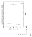
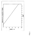
制御設計は、マサチューセッツ州ケンブリッジに事務所を有するActive Control Experts, Inc.から商業的に入手可能な、Smart IDEMシステム同定ソフトウエアパッケージを使用した転送関数データから最初に状態/空間プラントモデルを作成することによって、出願人によって達成される(本明細書の一部として本願に援用する共通人所有の米国特許出願第09/896,689号を参照のこと)。次いで、該フィードバック制御アルゴリズムは、コンピュータシミュレーション、およびFanson and The Control Handbook, William S. Levine, Editor, CRC Press, 1996に述べられた技術の応用によって設計された。該アルゴリズムを設計するために、線型二次レギュレータアプローチまたは古典的制御法を含む種々の制御設計技術を使用することができる。デトレンドされた信号を発生させるために、位置制御信号から命令された信号が差引かれる。該デトレンドされた信号は、振動を低減する目的のためのフィードバック測定値として使用される。該位置測定値信号が、時間の関数としての実際のステージ位置が望ましい応答に対応することを示すときに、成功が達成される。図9は、ウェハステージに振動が存在しない場合に、時間の関数としてのウェハステージの好ましい位置を示している。しかし、当該ステージに構造的振動が存在すれば、図10に示すように、位置 vs.時間のプロットは振動を含むであろう。この振動は、t=0からt=1までの直線からの±5単位の偏位として観察される。図9および図10においては、当該ランプ移動の開始(時間t=0の前)および該ランプ移動の最後(時間t=1の後)が除去される結果、ランプ運動の開始および停止に起因する振動は、この例では考慮する必要がない。しかし、ここに説明する技術は、振動が考慮されなくても等しく適用できるであろう。 Control design initially creates a state / space plant model from transfer function data using the Smart IDEM system identification software package, commercially available from Active Control Experts, Inc., with offices in Cambridge, Massachusetts (See commonly owned US patent application Ser. No. 09 / 896,689, which is incorporated herein by reference). The feedback control algorithm was then designed by computer simulation and application of techniques described in Fanson and The Control Handbook, William S. Levine, Editor, CRC Press, 1996. Various control design techniques can be used to design the algorithm, including linear secondary regulator approaches or classical control methods. The commanded signal is subtracted from the position control signal to generate a detrended signal. The detrended signal is used as a feedback measurement for the purpose of reducing vibrations. Success is achieved when the position measurement signal indicates that the actual stage position as a function of time corresponds to the desired response. FIG. 9 shows the preferred position of the wafer stage as a function of time when there is no vibration on the wafer stage. However, if there is structural vibration in the stage, the position vs. time plot will include vibration, as shown in FIG. This vibration is observed as a deviation of ± 5 units from the straight line from t = 0 to t = 1. In FIGS. 9 and 10, the start of the ramp movement (before time t = 0) and the end of the ramp movement (after time t = 1) are removed, resulting in the start and stop of the ramp movement. Vibrations need not be considered in this example. However, the techniques described herein would be equally applicable without considering vibration.
この実施形態において、リソグラフィーシステムのためのウェハステージの可動部分は、典型的には約1140kgの重量を有する。典型的には、線型磁気アクチュエータまたは音声コイルが、マスクに対してウェハを移動(走査)するために使用されるであろう。最新のリソグラフィーシステムにおいて、走査距離(その間にレチクルが照射され、次いでウェハの照射が行われる)は略300mmである(ウェハのサイズに対応する)。しかし、このデトレンディング法およびシステムは、モータおよび質量が対応して更に小さいような小さいシステムについても等しく働くであろう。或る人は、当該システムおよび方法が、10分の1グラムと小さい質量および少なくとも数千キログラムと大きい質量でも機能すると予想するであろう。また、このアプローチは、ディスクドライブヘッドがコンピュータのハードドライブを走査してデータを読取りまたは書込みするときに、ディスクドライブサスペンジョンにおける振動を低減することが望まれるような、ディスクドライブ適用においても等しく働くであろうと予想される。式2は、ウェハステージの例について、サーボ信号(未知のオフセットおよび傾斜のランプ)の命令された部分を記述している。図8に記載されたデトレンディング法のウェハステージへの応用は、図11における測定値100により示された振動信号を生じるであろう。このウェハステージへの上記で述べたフィードバック制御法の適用は、測定値110によって示されるように、該位置測定において観察された振動を減衰させる効果を有するであろう。
In this embodiment, the movable part of the wafer stage for the lithography system typically has a weight of about 1140 kg. Typically, a linear magnetic actuator or voice coil will be used to move (scan) the wafer relative to the mask. In modern lithography systems, the scanning distance (in which the reticle is irradiated and then the wafer is irradiated) is approximately 300 mm (corresponding to the size of the wafer). However, this detrending method and system will work equally well for small systems where the motor and mass are correspondingly smaller. Some would expect the system and method to work with masses as small as 1/10 gram and as large as at least several thousand kilograms. This approach also works equally well in disk drive applications where it is desirable to reduce vibration in the disk drive suspension as the disk drive head scans the computer hard drive to read or write data. Expected to be.
<均等物>
特定の好ましい実施形態を参照して本発明を具体的に示してきたが、当業者は、特許請求の範囲によって定義された本発明の精神および範囲を逸脱することなく、形態および詳細において種々の変更がなされ得ることを理解すべきである。可能な変更には下記のものが含まれる。
<Equivalent>
Although the invention has been particularly shown with reference to certain preferred embodiments, those skilled in the art will recognize that various forms and details can be made without departing from the spirit and scope of the invention as defined by the claims. It should be understood that changes can be made. Possible changes include the following:
1)多重軸(x、y、zおよびx、y、zの周りの回転)が、一つのコントローラを使用して制御される。
2)当該システムの特性を、種々のサーボ運動(ステップ、走査、多重平面内での運動、パラボラ運動)のために最適化できる。
3)位置センサは、容量ギャップセンサのような、干渉計システム以外の主知の種々の位置センサの何れであってもよい。
4)位置センサには、加速度計、速度計のような、変位量の導関数を測定するセンサが含まれる。
5)多くのドライブを、(音声コイル、線型磁気アクチュエータおよびエレクトロセラミックアクチュエータに加えて)使用することができる。
6)本発明は、上記で述べたリソグラフィー装置に加えて、計測装置および検査装置、ピックアップおよび配置装置、光学部品製造装置などのような多くのタイプの装置に適用できるであろう。
7)当該振動低減フィードバックコントローラは、SISOもしくはMIMOコントローラであってよい。MIMOコントローラは、線型二次ガウス(LQG)技術、またはmu-合成(mu-synthesis)、またはH-無限大(H-infinity)技術に基づいている。
1) Multiple axes (x, y, z and rotation around x, y, z) are controlled using one controller.
2) The characteristics of the system can be optimized for various servo motions (step, scan, motion in multiple planes, parabolic motion).
3) The position sensor may be any of various known position sensors other than the interferometer system, such as a capacitive gap sensor.
4) Position sensors include sensors that measure the derivative of the amount of displacement, such as accelerometers and speedometers.
5) Many drives can be used (in addition to voice coils, linear magnetic actuators and electroceramic actuators).
6) In addition to the lithography apparatus described above, the present invention may be applied to many types of apparatuses such as measurement and inspection apparatuses, pickup and arrangement apparatuses, optical component manufacturing apparatuses, and the like.
7) The vibration reduction feedback controller may be a SISO or MIMO controller. MIMO controllers are based on linear quadratic Gaussian (LQG) technology, or mu-synthesis, or H-infinity technology.
従って読者は、与えあれた実施例によってではなく、特許請求の範囲およびその法的均等物によって本発明の範囲を決定することが要求される。 Accordingly, the reader is required to determine the scope of the invention by the claims and their legal equivalents, rather than by the examples given.
Claims (11)
A)前記運動を制御された部品を移動させるための、少なくとも一つの位置制御ドライブと;
B)前記運動を制御された部品の位置を示すフィードバック位置信号を提供するための、少なくとも一つの位置センサと;
C)前記少なくとも一つのセンサからのフィードバック信号を利用する前記少なくとも一つの位置制御ドライブを介して、前記運動を制御されたステージの位置を制御するための、少なくとも一つの位置制御システムと;
D)少なくとも一つの振動制御ドライブと;
E)下記の(1)および(2)をプログラムされている、振動を制御するためのコンピュータプロセッサ;
(1)前記フィードバック位置信号から振動信号を分離するための分離アルゴリ
ズム;および
(2)前記運動を制御された部品における振動を低減するように、前記振動制御
ドライブに命令を与えるためのフィードバック制御アルゴリズム
とを具備するシステム。 A vibration reduction system for reducing the vibration of a part whose movement is controlled:
A) at least one position control drive for moving the motion controlled part;
B) at least one position sensor for providing a feedback position signal indicative of the position of the movement controlled part;
C) at least one position control system for controlling the position of the motion controlled stage via the at least one position control drive utilizing a feedback signal from the at least one sensor;
D) at least one vibration control drive;
E) A computer processor for controlling vibrations programmed (1) and (2) below;
(1) A separation algorithm for separating a vibration signal from the feedback position signal
And (2) the vibration control to reduce vibrations in the motion controlled component.
A feedback control algorithm for providing commands to the drive.
Applications Claiming Priority (3)
| Application Number | Priority Date | Filing Date | Title |
|---|---|---|---|
| US10/074,059 US6563128B2 (en) | 2001-03-09 | 2002-02-11 | Base stabilization system |
| US10/112,443 US6872961B2 (en) | 2000-01-27 | 2002-03-29 | Vibration control utilizing signal detrending |
| PCT/US2003/001332 WO2003069733A1 (en) | 2002-02-11 | 2003-01-15 | Vibration control utilizing signal detrending |
Publications (2)
| Publication Number | Publication Date |
|---|---|
| JP2005517875A true JP2005517875A (en) | 2005-06-16 |
| JP2005517875A5 JP2005517875A5 (en) | 2006-03-02 |
Family
ID=27736817
Family Applications (1)
| Application Number | Title | Priority Date | Filing Date |
|---|---|---|---|
| JP2003568738A Pending JP2005517875A (en) | 2002-02-11 | 2003-01-15 | Vibration control using signal detrending |
Country Status (5)
| Country | Link |
|---|---|
| US (1) | US6872961B2 (en) |
| EP (1) | EP1474844B1 (en) |
| JP (1) | JP2005517875A (en) |
| AU (1) | AU2003212805A1 (en) |
| WO (1) | WO2003069733A1 (en) |
Cited By (1)
| Publication number | Priority date | Publication date | Assignee | Title |
|---|---|---|---|---|
| JP2011505025A (en) * | 2007-11-28 | 2011-02-17 | マイ ミュージック マシンズ インコーポレイテッド | Adaptive MIDI wind control system |
Families Citing this family (10)
| Publication number | Priority date | Publication date | Assignee | Title |
|---|---|---|---|---|
| US20050271110A1 (en) * | 2003-08-22 | 2005-12-08 | Rainer Paetzel | Excimer laser system with stable beam output |
| DE502006005980D1 (en) * | 2006-05-20 | 2010-03-11 | Integrated Dynamics Eng Gmbh | Active vibration isolation system with a combined position actuator |
| US7782446B2 (en) | 2007-03-01 | 2010-08-24 | Asml Netherlands B.V. | Stage system and lithographic apparatus comprising such stage system |
| EP2119938A1 (en) * | 2008-05-15 | 2009-11-18 | Nederlandse Organisatie voor toegepast-natuurwetenschappelijk Onderzoek TNO | A vibration sensor and a system to isolate vibrations. |
| DE102012004808A1 (en) * | 2012-03-09 | 2013-09-12 | Fraunhofer-Gesellschaft zur Förderung der angewandten Forschung e.V. | Device for influencing the vibration transmission between two units |
| US9837939B1 (en) | 2015-04-01 | 2017-12-05 | Lockheed Martin Corporation | System and method for providing vibration isolation by magnetic levitation |
| US9964966B1 (en) * | 2015-09-28 | 2018-05-08 | Amazon Technologies, Inc. | Controlling mechanical vibrations |
| KR102566136B1 (en) * | 2016-10-14 | 2023-08-10 | 삼성전자주식회사 | Metrology system and stage control device using the same |
| TWI728762B (en) * | 2020-03-27 | 2021-05-21 | 財團法人工業技術研究院 | Method for reducing vibration of robot arm |
| CN113031669B (en) * | 2021-02-10 | 2022-04-22 | 国机集团科学技术研究院有限公司 | High-quality crystal cultivation key process environment vibration control technical analysis method |
Family Cites Families (10)
| Publication number | Priority date | Publication date | Assignee | Title |
|---|---|---|---|---|
| IL77057A (en) * | 1985-03-26 | 1990-03-19 | Wright Barry Corp | Active vibration isolation system |
| US6959484B1 (en) * | 1994-01-27 | 2005-11-01 | Cymer, Inc. | System for vibration control |
| US5811821A (en) * | 1996-08-09 | 1998-09-22 | Park Scientific Instruments | Single axis vibration reducing system |
| JPH1089403A (en) | 1996-09-10 | 1998-04-07 | Nikon Corp | Vibration control device |
| JP3825869B2 (en) * | 1997-03-19 | 2006-09-27 | キヤノン株式会社 | Active vibration isolator |
| AU1172699A (en) * | 1997-11-18 | 1999-06-07 | Nikon Corporation | Vibration eliminator, aligner and projection exposure method |
| US6260282B1 (en) * | 1998-03-27 | 2001-07-17 | Nikon Corporation | Stage control with reduced synchronization error and settling time |
| JP4109747B2 (en) * | 1998-05-07 | 2008-07-02 | キヤノン株式会社 | Active vibration isolator and exposure apparatus |
| US6563128B2 (en) * | 2001-03-09 | 2003-05-13 | Cymer, Inc. | Base stabilization system |
| US6650666B2 (en) | 2000-02-09 | 2003-11-18 | Cymer, Inc. | Laser wavelength control unit with piezoelectric driver |
-
2002
- 2002-03-29 US US10/112,443 patent/US6872961B2/en not_active Expired - Lifetime
-
2003
- 2003-01-15 EP EP03708837.4A patent/EP1474844B1/en not_active Expired - Fee Related
- 2003-01-15 JP JP2003568738A patent/JP2005517875A/en active Pending
- 2003-01-15 AU AU2003212805A patent/AU2003212805A1/en not_active Abandoned
- 2003-01-15 WO PCT/US2003/001332 patent/WO2003069733A1/en active Application Filing
Cited By (1)
| Publication number | Priority date | Publication date | Assignee | Title |
|---|---|---|---|---|
| JP2011505025A (en) * | 2007-11-28 | 2011-02-17 | マイ ミュージック マシンズ インコーポレイテッド | Adaptive MIDI wind control system |
Also Published As
| Publication number | Publication date |
|---|---|
| EP1474844A4 (en) | 2006-02-22 |
| EP1474844B1 (en) | 2017-03-22 |
| EP1474844A1 (en) | 2004-11-10 |
| WO2003069733A1 (en) | 2003-08-21 |
| AU2003212805A1 (en) | 2003-09-04 |
| US6872961B2 (en) | 2005-03-29 |
| US20030041447A1 (en) | 2003-03-06 |
Similar Documents
| Publication | Publication Date | Title |
|---|---|---|
| US5504407A (en) | Stage driving system | |
| US6563128B2 (en) | Base stabilization system | |
| KR100331771B1 (en) | Exposure apparatus | |
| US6903806B2 (en) | Stage control apparatus, exposure apparatus, and device manufacturing method | |
| US20020099475A1 (en) | Method and device for vibration control | |
| US6742393B2 (en) | Vibration control apparatus, vibration control method, exposure apparatus, and device manufacturing method | |
| US6872961B2 (en) | Vibration control utilizing signal detrending | |
| US9791018B2 (en) | Vibration isolation apparatus, method of isolating vibration, lithography apparatus, and method of producing device | |
| EP1124078A2 (en) | Active anti-vibration apparatus and exposure apparatus | |
| JP4386293B2 (en) | Vibration control apparatus, vibration control method, exposure apparatus, and device manufacturing method | |
| WO2018020625A1 (en) | Charged particle radiation device | |
| US5714860A (en) | Stage device capable of applying a damping force to a movable member | |
| EP2869121B1 (en) | Computer-readable storage medium, generating method, generating apparatus, driving apparatus, processing apparatus, lithography apparatus, and method of manufacturing article | |
| JP2004111653A (en) | Positioning device, exposure device applying the locating device thereto and manufacturing method of semiconductor device | |
| US20220299889A1 (en) | Method of controlling a position of a first object relative to a second object, control unit, lithographic apparatus and apparatus | |
| KR20230012976A (en) | Processing apparatus and article manufacturing method | |
| JP2003324056A (en) | Vibration suppression device, control method therefor, aligner and method of manufacturing semiconductor device | |
| CN116913804A (en) | Stage device, charged particle beam device, and optical inspection device |
Legal Events
| Date | Code | Title | Description |
|---|---|---|---|
| A521 | Written amendment |
Free format text: JAPANESE INTERMEDIATE CODE: A523 Effective date: 20060111 |
|
| A621 | Written request for application examination |
Free format text: JAPANESE INTERMEDIATE CODE: A621 Effective date: 20060111 |
|
| A131 | Notification of reasons for refusal |
Free format text: JAPANESE INTERMEDIATE CODE: A131 Effective date: 20090209 |
|
| A601 | Written request for extension of time |
Free format text: JAPANESE INTERMEDIATE CODE: A601 Effective date: 20090511 |
|
| A602 | Written permission of extension of time |
Free format text: JAPANESE INTERMEDIATE CODE: A602 Effective date: 20090518 |
|
| A601 | Written request for extension of time |
Free format text: JAPANESE INTERMEDIATE CODE: A601 Effective date: 20090609 |
|
| A602 | Written permission of extension of time |
Free format text: JAPANESE INTERMEDIATE CODE: A602 Effective date: 20090616 |
|
| A521 | Written amendment |
Free format text: JAPANESE INTERMEDIATE CODE: A523 Effective date: 20090709 |
|
| A02 | Decision of refusal |
Free format text: JAPANESE INTERMEDIATE CODE: A02 Effective date: 20091019 |