JP2005512077A - Current controller bias to protect the ring laser gyroscope electrode seal - Google Patents
Current controller bias to protect the ring laser gyroscope electrode seal Download PDFInfo
- Publication number
- JP2005512077A JP2005512077A JP2003551482A JP2003551482A JP2005512077A JP 2005512077 A JP2005512077 A JP 2005512077A JP 2003551482 A JP2003551482 A JP 2003551482A JP 2003551482 A JP2003551482 A JP 2003551482A JP 2005512077 A JP2005512077 A JP 2005512077A
- Authority
- JP
- Japan
- Prior art keywords
- mounting structure
- electrodes
- frame
- ring laser
- gyroscope
- Prior art date
- Legal status (The legal status is an assumption and is not a legal conclusion. Google has not performed a legal analysis and makes no representation as to the accuracy of the status listed.)
- Pending
Links
Images


Classifications
-
- G—PHYSICS
- G01—MEASURING; TESTING
- G01C—MEASURING DISTANCES, LEVELS OR BEARINGS; SURVEYING; NAVIGATION; GYROSCOPIC INSTRUMENTS; PHOTOGRAMMETRY OR VIDEOGRAMMETRY
- G01C19/00—Gyroscopes; Turn-sensitive devices using vibrating masses; Turn-sensitive devices without moving masses; Measuring angular rate using gyroscopic effects
- G01C19/58—Turn-sensitive devices without moving masses
- G01C19/64—Gyrometers using the Sagnac effect, i.e. rotation-induced shifts between counter-rotating electromagnetic beams
- G01C19/66—Ring laser gyrometers
- G01C19/661—Ring laser gyrometers details
-
- H—ELECTRICITY
- H01—ELECTRIC ELEMENTS
- H01S—DEVICES USING THE PROCESS OF LIGHT AMPLIFICATION BY STIMULATED EMISSION OF RADIATION [LASER] TO AMPLIFY OR GENERATE LIGHT; DEVICES USING STIMULATED EMISSION OF ELECTROMAGNETIC RADIATION IN WAVE RANGES OTHER THAN OPTICAL
- H01S3/00—Lasers, i.e. devices using stimulated emission of electromagnetic radiation in the infrared, visible or ultraviolet wave range
- H01S3/05—Construction or shape of optical resonators; Accommodation of active medium therein; Shape of active medium
- H01S3/08—Construction or shape of optical resonators or components thereof
- H01S3/081—Construction or shape of optical resonators or components thereof comprising three or more reflectors
- H01S3/083—Ring lasers
-
- H—ELECTRICITY
- H01—ELECTRIC ELEMENTS
- H01S—DEVICES USING THE PROCESS OF LIGHT AMPLIFICATION BY STIMULATED EMISSION OF RADIATION [LASER] TO AMPLIFY OR GENERATE LIGHT; DEVICES USING STIMULATED EMISSION OF ELECTROMAGNETIC RADIATION IN WAVE RANGES OTHER THAN OPTICAL
- H01S3/00—Lasers, i.e. devices using stimulated emission of electromagnetic radiation in the infrared, visible or ultraviolet wave range
- H01S3/02—Constructional details
- H01S3/03—Constructional details of gas laser discharge tubes
- H01S3/034—Optical devices within, or forming part of, the tube, e.g. windows, mirrors
- H01S3/0346—Protection of windows or mirrors against deleterious effects
-
- H—ELECTRICITY
- H01—ELECTRIC ELEMENTS
- H01S—DEVICES USING THE PROCESS OF LIGHT AMPLIFICATION BY STIMULATED EMISSION OF RADIATION [LASER] TO AMPLIFY OR GENERATE LIGHT; DEVICES USING STIMULATED EMISSION OF ELECTROMAGNETIC RADIATION IN WAVE RANGES OTHER THAN OPTICAL
- H01S3/00—Lasers, i.e. devices using stimulated emission of electromagnetic radiation in the infrared, visible or ultraviolet wave range
- H01S3/02—Constructional details
- H01S3/03—Constructional details of gas laser discharge tubes
- H01S3/038—Electrodes, e.g. special shape, configuration or composition
- H01S3/0388—Compositions, materials or coatings
-
- H—ELECTRICITY
- H01—ELECTRIC ELEMENTS
- H01S—DEVICES USING THE PROCESS OF LIGHT AMPLIFICATION BY STIMULATED EMISSION OF RADIATION [LASER] TO AMPLIFY OR GENERATE LIGHT; DEVICES USING STIMULATED EMISSION OF ELECTROMAGNETIC RADIATION IN WAVE RANGES OTHER THAN OPTICAL
- H01S3/00—Lasers, i.e. devices using stimulated emission of electromagnetic radiation in the infrared, visible or ultraviolet wave range
- H01S3/05—Construction or shape of optical resonators; Accommodation of active medium therein; Shape of active medium
- H01S3/08—Construction or shape of optical resonators or components thereof
- H01S3/081—Construction or shape of optical resonators or components thereof comprising three or more reflectors
- H01S3/083—Ring lasers
- H01S3/0835—Gas ring lasers
Abstract
電極封止部を保護するために、リングレーザジャイロスコープの電流制御器バイアスが採用される。リングレーザジャイロスコープのフレーム214は、これに装着される2つ以上の電極206、212を有する。電場は、ジャイロスコープの動作中に電極間に創出され、これが、フレーム内のイオンを最低電位に向けて移動させる。電極封止部210は、電極とフレームの間に位置する。正の電源電圧Vsを供給すること、および、電流制御器202を電源204の非アース側に接続することにより、搭載構造体208は、最低電位とすることができる。したがって、イオンは、搭載構造体に向かって移動し、これが、電極への移動を大幅に低減する。 A ring laser gyroscope current controller bias is employed to protect the electrode seal. The ring laser gyroscope frame 214 has two or more electrodes 206, 212 attached to it. An electric field is created between the electrodes during the operation of the gyroscope, which moves the ions in the frame towards the lowest potential. The electrode sealing part 210 is located between the electrode and the frame. By supplying the positive power supply voltage Vs and connecting the current controller 202 to the non-ground side of the power supply 204, the mounting structure 208 can be at the lowest potential. Thus, the ions move toward the mounting structure, which greatly reduces movement to the electrodes.
Description
本発明は、一般的に、リングレーザジャイロスコープに関し、より詳細には、電極の封止部の劣化を防止する方法に関する。 The present invention relates generally to ring laser gyroscopes, and more particularly to a method for preventing degradation of electrode seals.
リングレーザジャイロスコープは、Sagnac効果に従う2つの逆回転レーザビーム間の周波数差を測定することにより、角速度を検出および測定する。2つのレーザビームは、ジャイロスコープの空洞内を同時に循環する。各ビームを空洞周辺に反射するために、ミラーが使用される。センサが休止している時、2つのレーザビームは、同一の周波数を理想的に有する。センサが回転されれば、それらのビームは、異なる周波数を有する。この周波数差は、回転の速度を提供するために測定される。 A ring laser gyroscope detects and measures angular velocity by measuring the frequency difference between two counter-rotating laser beams that follow the Sagnac effect. The two laser beams circulate simultaneously in the gyroscope cavity. A mirror is used to reflect each beam around the cavity. When the sensor is at rest, the two laser beams ideally have the same frequency. If the sensors are rotated, their beams have different frequencies. This frequency difference is measured to provide the speed of rotation.
ジャイロスコープは、航行、安定化、誘導、および、制御の応用例で使用され、航空機、船舶、タンク、パイプライン、および、ミサイルに設置される。応用例は、全般に、単一または短い期間の用途、および、継続的または長い期間の用途の2つの分類の1つの中に該当する。リングレーザジャイロスコープの単一用途の応用の例は、ミサイルの応用例である。ジャイロスコープは、ミサイルをその目標に誘導し、衝撃を受けると破壊される。このタイプのジャイロスコープは、分単位で測定することができる動作寿命を有し、継続的な用途のジャイロスコープがさらされる過酷な動作条件にはさらされない。単一用途のリングレーザジャイロスコープは、継続的用途のジャイロスコープより一般に小さく、それらとは異なる材料で製造される。 Gyroscopes are used in navigation, stabilization, guidance, and control applications and are installed in aircraft, ships, tanks, pipelines, and missiles. Application examples generally fall into one of two categories: single or short term applications and continuous or long term applications. An example of a single use application of a ring laser gyroscope is a missile application. A gyroscope guides a missile to its target and is destroyed when impacted. This type of gyroscope has an operational life that can be measured in minutes and is not exposed to the harsh operating conditions to which continuous use gyroscopes are exposed. Single-use ring laser gyroscopes are generally smaller than continuous-use gyroscopes and are made of different materials.
リングレーザジャイロスコープの継続的用途応用の例は、航空機の応用例である。商用機上のリングレーザジャイロスコープの動作寿命は、10から20年になることもある。このジャイロスコープは、延長された時間にわたる極端な温度および圧力の変動にさらされる。継続的用途のジャイロスコープが動作することがある極端な条件のために、このタイプのジャイロスコープのフレームは、広い温度範囲にわたる膨張に対して耐性を持つ材料を使用して製造されなければならない。1つのそのような材料は、極端に小さな熱膨張係数を持つガラスセラミック材料であるZerodurである。 An example of a continuous use application of a ring laser gyroscope is an aircraft application. The operational life of a ring laser gyroscope on a commercial machine can be 10 to 20 years. This gyroscope is subject to extreme temperature and pressure fluctuations over an extended period of time. Due to the extreme conditions under which continuous use gyroscopes may operate, this type of gyroscope frame must be manufactured using materials that are resistant to expansion over a wide temperature range. One such material is Zerodur, a glass ceramic material with an extremely small coefficient of thermal expansion.
このタイプのフレーム材料を使用するうえでの問題の1つは、その材料が他の誘電体材料より大きなイオン伝導度値を有する傾向を持つことである。これらのフレーム材料は、電場の存在下で高度に可動であるアルカリ性イオンを含む。このイオンは、ジャイロスコープのフレーム上に搭載されるカソードに引き寄せられる。なぜなら、ジャイロスコープに電力を印加する典型的な方法のために、それが最も低い電位にあるからである。カソードへのアルカリ性イオンの移動は、カソードとフレームとの間に位置する封止部上に、イオンの豊富な層を堆積させる。 One problem with using this type of frame material is that it tends to have a higher ionic conductivity value than other dielectric materials. These frame materials contain alkaline ions that are highly mobile in the presence of an electric field. The ions are attracted to the cathode mounted on the gyroscope frame. This is because it is at the lowest potential because of the typical method of applying power to the gyroscope. The movement of alkaline ions to the cathode deposits an ion-rich layer on the seal located between the cathode and the frame.
インジウムは、セラミックと金属の双方に固着し、熱膨張の存在下でもその真空封止を失わないというその独特な特性のために、封止部材料として頻繁に選択される。ジャイロスコープの適切な動作のために、この封止部は、劣化して、レーザを発する気体を逃れさせてはならない。したがって、封止部の劣化を防止する必要性がある。 Indium is frequently selected as a seal material because of its unique property of sticking to both ceramic and metal and not losing its vacuum seal in the presence of thermal expansion. For proper operation of the gyroscope, this seal must not deteriorate and allow the laser emitting gas to escape. Therefore, there is a need to prevent deterioration of the sealing portion.
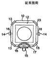
米国特許第5,856,995号明細書、「Ring Laser Gyroscope with Ion Flux Trap Electrode」は、イオンがカソードに移動する前にイオンをトラップする方法を説明した。この方法は、図1に見られるように、電極リングがカソードを取り囲むフレームと電気的な直接接触に置かれることを必要とする。電極リングは、カソードよりも負側の電位を有する。これがイオンをカソードではなくリングに引き寄せ、イオンが封止部を劣化させることを防止する。電極リングは、導電性接着剤が付着した銅の薄いシートで作ることができ、薄い金属膜が真空蒸着により施されるか、機械加工された金属合金が機械的手段により装着されるか、または、導電性インクがフレーム表面上に塗られる。 US Pat. No. 5,856,995, “Ring Laser Gyroscope with Ion Flex Trap Electrode” described a method of trapping ions before they migrate to the cathode. This method requires that the electrode ring be placed in direct electrical contact with the frame surrounding the cathode, as seen in FIG. The electrode ring has a potential on the negative side of the cathode. This attracts ions to the ring, not the cathode, preventing the ions from degrading the seal. The electrode ring can be made of a thin sheet of copper with conductive adhesive attached, a thin metal film is applied by vacuum deposition, a machined metal alloy is attached by mechanical means, or A conductive ink is applied on the surface of the frame.
他の技術は、本発明と同じ譲受人に譲渡された米国特許第6,025914号明細書、「Cathode Seal Including Migration Resistant Dielectric Material」に述べられる。この方法は、図2に見られるように、ジャイロスコープのフレームとカソードの間に誘電体障壁材料を追加する。誘電体障壁材料層は、ジャイロスコープのフレームに形成される電場を低減し、したがって、イオンの移動を低減する。誘電体障壁は、蒸着、または、カソードとフレームの間に材料のシートを溶接することにより形成することができる。 Other techniques are described in US Pat. No. 6,025914, “Cathode Seal Inclusion Migration Dielectric Material”, assigned to the same assignee as the present invention. This method adds a dielectric barrier material between the gyroscope frame and the cathode, as seen in FIG. The dielectric barrier material layer reduces the electric field formed in the gyroscope frame and thus reduces ion migration. The dielectric barrier can be formed by vapor deposition or welding a sheet of material between the cathode and the frame.
リングレーザジャイロスコープの製造工程を修正せずに、電極封止部上にイオン層が形成されることを防止することが望ましい。 It is desirable to prevent the ion layer from being formed on the electrode sealing portion without modifying the manufacturing process of the ring laser gyroscope.
リングレーザジャイロスコープ上の電極封止部を保護するための電流制御器バイアスの使用に対する例示的実施形態が説明される。封止部は、ジャイロスコープのフレームと電極の各々との間に位置する。ジャイロスコープが通電されると、フレーム内のイオンは、より低い電位に向かって全体的に移動する。電極の1つが最も低い電位にある場合、イオンは、電極封止部上に層を形成し、これを劣化させる。電源の非アース側に正の電源電圧を供給し、ここに電流制御を位置させることによって、搭載構造体は、最も低い電位となる。 An exemplary embodiment for the use of a current controller bias to protect an electrode seal on a ring laser gyroscope is described. The seal is located between the gyroscope frame and each of the electrodes. When the gyroscope is energized, the ions in the frame move globally toward a lower potential. When one of the electrodes is at the lowest potential, the ions form a layer on the electrode seal and degrade it. By supplying a positive power supply voltage to the non-ground side of the power supply and locating the current control here, the mounting structure is at the lowest potential.
本発明の本好ましい実施形態を、様々な図面において同じ参照番号が同じ要素を指す添付の図面に関連して、以下に説明する。 The presently preferred embodiments of the invention are described below with reference to the accompanying drawings, wherein like reference numerals refer to like elements in the various drawings.
図3は、リングレーザジャイロスコープシステム100の概略を与え、これは、リングレーザジャイロスコープ118、電流制御器102、電源104、および、搭載構造体108を含む。
FIG. 3 provides an overview of a ring
リングレーザジャイロスコープ118は、フレーム114、電極106、112、電極封止部110、空洞、および、ミラーから構成される。フレーム114は、極端に小さな熱膨張係数を有するZerodurなどのガラスセラミックから構成することができる。他のフレーム材料も適することがある。例示的な実施形態において、フレーム114上に位置する電極は、1つのカソード106および2つのアノード112を含むが、他の配置構成も可能である。例えば、リングレーザジャイロスコープ118は、2つのカソード106および1つのアノード112を有することができる。電極封止部110は、フレーム114と電極106、112の各々との間に位置する。例示的実施形態における電極封止部110は、インジウムで構成される。スズ、鉛、または、インジウム、スズ、もしくは、鉛で作る合金などの他の材料も、封止部を構成するために使用することができる。ジャイロスコープ118の空洞は、フレーム114内に位置する。ミラーは、レーザビームを空洞周辺に指し向けるために使用される。空洞およびミラーは、図3に示さない。
The
電源104は、電流制御器102とカソード106の間に位置することができる。電源104は、アース116に電気的に接続される1つの側と、非アース側に電気的に接続される他の側とを有することができる。電流制御器102は、安定抵抗120を介してリングレーザジャイロスコープ118のフレーム114上のアノード112に接続される。電流制御器102は、アノード112に進入する電流を一定のレベルに保持するために使用することができる。安定抵抗120は、採用されるリングレーザジャイロスコープ118の大きさおよびレーザを発する気体のタイプに基づき選択され、レーザを発する気体の発振を最小に抑えるために使用される。
The power source 104 can be located between the
フレーム114は、搭載構造体108上に搭載される。例示的な実施形態における搭載構造体108は、ディザモータ(dither motor)である。他の搭載構造体も採用可能である。
The
図3は、リングレーザジャイロスコープシステム100に電力を供給する典型的な方法を表す概略図である。電源104は、ジャイロスコープ118に負の電圧を供給する。典型的な供給値は−500ボルトであるが、他の負電圧も使用することができる。電流制御器102は、電源104のアース116側に接続される。これは、電流の不釣合いを引き起こすことがある漏れ電流を最小に抑えるために、電流制御器102がアースまたはその付近に留まることを可能にする。カソード106は、搭載構造体108に関して負にバイアスをかけることができる。もしカソード106がリングレーザジャイロスコープシステム100の最低電位にあれば、イオンは、これに移動することができる。イオンは、カソード106に関する電極封止部110上に層を形成することができ、これが封止部110を時間と共に劣化させることがある。
FIG. 3 is a schematic diagram representing an exemplary method of supplying power to ring
図4は、リングレーザジャイロスコープシステム200に電力を供給する例示的実施形態の概略図である。リングレーザジャイロスコープシステム200は、リングレーザジャイロスコープ218、電流制御器202、電源204、および、搭載構造体208を含む。リングレーザジャイロスコープ218および搭載構造体208は、リングレーザジャイロスコープシステム100のリングレーザジャイロスコープ118および搭載構造体108と実質的に同じとすることができる。
FIG. 4 is a schematic diagram of an exemplary embodiment for supplying power to a ring
リングレーザジャイロスコープ218は、フレーム214、カソード206、2つのアノード212、電極封止部210、空洞、および、ミラーから構成される。電極封止部210は、フレーム214とカソード206およびアノード212の各々との間に位置する。ジャイロスコープ218の空洞は、フレーム214内に位置する。ミラーは、レーザビームを空洞周辺に指し向けるために使用される。空洞およびミラーは、図4には示さない。
The
電源204は、電流制御器202とカソード206の間に位置する。電源204のアース216側は、カソード206に接続され、非アース側は、電流制御器202に接続される。電流制御器202は、安定抵抗220を介してリングレーザジャイロスコープ218上のアノード212に接続される。抵抗値は、採用されるリングレーザジャイロスコープ218の大きさおよびレーザを発する気体のタイプに基づき選択される。
A
図5は、例示的電圧値を示す例示的実施形態の概略図である。電源204は、正の電源電圧を供給する。典型的な供給電圧は、+600ボルトであるが、供給値は、採用されるリングレーザジャイロスコープ218の大きさおよびレーザを発する気体のタイプに基づく。より大きなジャイロスコープ218およびレーザを発する気体のより高い圧力は、より高い供給値を必要とすることがある。
FIG. 5 is a schematic diagram of an exemplary embodiment showing exemplary voltage values. The
正の電源電圧を供給すること、および、電源204の非アース側に電流制御器202を位置させることによって、搭載構造体208とカソード206の双方とも、リングレーザジャイロスコープシステム200の最低電位となることができる。この時、イオンの拡散は、搭載構造体208およびカソード106の双方に向かい、かつ、アノード112から離れるように指し向けることができる。アノード212と搭載構造体208の間のインピーダンスが、アノード212とカソード206の間のインピーダンスより小さいため、イオンは、カソード206に到達する前に搭載構造体208に到達する。したがって、実質的に少ないイオンがカソード206に移動する。電極封止部210のイオン性劣化は、低減することができ、封止部210の寿命を延長し、それにより、ジャイロスコープ218の動作寿命を延長する。電極リングまたは誘電体障壁の追加などのリングレーザジャイロスコープ218の製造工程の修正は必要ない。
By providing a positive power supply voltage and positioning the
この例示的実施形態において、イオンは、搭載構造体208に向かって移動する。搭載構造体208は、ジャイロスコープ218の動作寿命の間のイオンの蓄積によって損害を受けないことが可能である。搭載構造体208がレーザを発する気体を含む空洞の一部を形成する可能性は低い。したがって、レーザを発する気体の空洞への漏れおよび汚染が、電極封止部210の故障形態となる可能性がある一方、これは、搭載構造体208の典型的な故障形態とはならない。
In this exemplary embodiment, the ions move toward the mounting
図6は、リングレーザジャイロスコープシステム300の例示的実施形態の概略図である。リングレーザジャイロスコープシステム300は、カソード抵抗322が追加されたリングレーザジャイロスコープシステム200と実質的に同じである。リングレーザジャイロスコープシステム300にカソード抵抗322を追加することにより、カソード306は、搭載構造体308より高い電位になることができる。搭載構造体308は、システム300の最低電位となることができる。したがって、イオンの移動は、搭載構造体308に向かって指し向けることができる。電極封止部310のイオン性劣化は、さらに低減され、封止部310の寿命を延長し、それにより、ジャイロスコープ318の動作寿命を延長する。リングレーザジャイロスコープ318の製造工程に対する修正は必要なく、搭載構造体は、ジャイロスコープ318の動作寿命の間、イオンの蓄積により損害を受けずにいることができる。
FIG. 6 is a schematic diagram of an exemplary embodiment of a ring
図7は、例示的な電流制御器402のブロック図を示す例示的なリングレーザジャイロスコープシステム400の概略図である。電流制御器402は、リングレーザジャイロスコープシステム200の電流制御器202と実質的に同じである。電流制御器402は、低電圧制御器および比較器回路406、低圧電源408、および、高電圧制御回路410を含むことができる。低圧電源408は、低電圧制御器および比較器回路406、および、高電圧制御回路410の双方に低圧電力を供給する。低圧電源408は、電源404の非アース側にも電気的に接続することができる。電源404は、リングレーザジャイロスコープシステム200の電源204と実質的に同じである。
FIG. 7 is a schematic diagram of an example ring laser gyroscope system 400 showing a block diagram of an example
低電圧制御器および比較器回路406は、リングレーザジャイロスコープ412に進入する電流の量を参照値と比較し、信号を高電圧制御回路410に送る。高電圧制御回路410は、リングレーザジャイロスコープ412に進入する定電流を実質的に維持する。リングレーザジャイロスコープ412は、リングレーザジャイロスコープシステム200のリングレーザジャイロスコープ218と実質的に同じである。
The low voltage controller and
ともに本発明と同じ譲受人に譲渡された米国特許第5,414,727号明細書、「Active Current Control Apparatus」、および、米国特許第5,271,027号明細書、「Gas Discharge Device Current Control Circuit」に概説されるものと同様の設計などの他の電流制御器の設計も、使用することができる。 US Pat. No. 5,414,727, “Active Current Control Apparatus”, and US Pat. No. 5,271,027, “Gas Discharge Device Current Control”, both assigned to the same assignee as the present invention. Other current controller designs can also be used, such as a design similar to that outlined in Circuit.
リングレーザジャイロスコープは、以前、ジャイロスコープが非常に短い動作寿命を有する単一または限定された用途の応用例において、正の供給電圧で電力を供給されていた。これらの応用例は、ジャイロスコープの動作寿命を分単位で測定することができるミサイル誘導システムを含む。電極封止部のイオン性劣化は、これらの応用例において動作上の問題とはならない。なぜなら、ジャイロスコープはイオンが層を形成するのを可能にするのに十分長い時間にわたっては動作しないからである。 Ring laser gyroscopes were previously powered with a positive supply voltage in single or limited application applications where the gyroscope has a very short operating life. These applications include missile guidance systems that can measure the operational life of a gyroscope in minutes. The ionic deterioration of the electrode sealing portion is not an operational problem in these applications. This is because the gyroscope does not operate for a time long enough to allow ions to form a layer.
加えて、単一または限定された用途の応用例で使用されるリングレーザジャイロスコープは、様々なタイプの電極封止材料および/またはフレーム材料を採用することができる。なぜなら、それらの応用例は、熱膨張が決定的な要因となる条件下でジャイロスコープが動作することを必要としなくてよいからである。例えば、フリット封止部を使用することができる。これらの封止部は、より少ないイオン性劣化を経験する。なぜなら、フリット封止部の結合エネルギが、インジウム封止部の結合エネルギよりもはるかに大きいからである。硬質ホウケイ酸クラウンガラスであるBK7などのフレーム材料を使用することができる。このタイプのフレーム材料から生成されるイオンは、より緩慢な拡散速度を有し、これが、イオン性劣化の問題を経験するためにかかる時間を延長する。 In addition, ring laser gyroscopes used in single or limited application applications can employ various types of electrode sealing materials and / or frame materials. This is because these applications do not require the gyroscope to operate under conditions where thermal expansion is a critical factor. For example, a frit seal can be used. These seals experience less ionic degradation. This is because the binding energy of the frit sealing portion is much larger than that of the indium sealing portion. A frame material such as BK7, which is a hard borosilicate crown glass, can be used. Ions generated from this type of frame material have a slower diffusion rate, which extends the time it takes to experience ionic degradation problems.
電極封止部を保護するために電流制御器バイアスは、リングレーザジャイロスコープが航空機、船舶、タンク、および、パイプラインの応用例におけるものなどの長期または継続的な用途の応用例を有する時にのみ必要とされる。例えば、商用機内に設置されるジャイロスコープの動作寿命は、10から20年になることもある。電極封止部のイオン性劣化の問題が問題点となるまでに、ジャイロスコープの動作の数年がかかることもある。封止部の劣化が発生するまでの時間の長さは、動作時間、上昇した温度、および、熱サイクルの組み合わせに基づく。イオンの拡散は、温度に強く依存することがあり、高温により多くさらされることは電極封止部が劣化する速度を上昇させることがある。例えば、高温の応用例を持つジャイロスコープと10年間の平均寿命は、ジャイロスコープの動作の2から3年後に電極封止部劣化の問題と遭遇する。加速動作寿命試験は、封止部へのイオンの拡散を低減することによる電極封止部の動作寿命の3から4倍の延長を実証することができる。例えば、電極封止部の動作寿命は、5,000時間から15,000時間に延長させることができる。リングレーザジャイロスコープの動作について実施形態が説明された一方、それらは、ジャイロスコープの製造にも適用できる。正の供給電圧を供給すること、および、電源の非アース側に電流制御器を定置することにより、電極封止部は、ジャイロスコープの販売前のフレームのバーンイン試験中にイオン性劣化から保護することができる。バーンイン試験は、納品前に欠陥を識別するために上昇させた温度で行われる。 Current controller bias to protect electrode seals is only when the ring laser gyroscope has long-term or continuous use applications such as those in aircraft, ship, tank, and pipeline applications Needed. For example, the operating life of a gyroscope installed in a commercial machine may be 10 to 20 years. It may take several years for the gyroscope to operate before the problem of ionic degradation of the electrode sealing portion becomes a problem. The length of time until degradation of the seal occurs is based on a combination of operating time, elevated temperature, and thermal cycle. Ion diffusion may be strongly temperature dependent, and more exposure to higher temperatures may increase the rate at which the electrode seal degrades. For example, gyroscopes with high temperature applications and a 10 year life expectancy will encounter electrode seal degradation problems after 2 to 3 years of gyroscope operation. The accelerated operating life test can demonstrate a 3 to 4 times increase in the operating life of the electrode seal by reducing the diffusion of ions into the seal. For example, the operating life of the electrode sealing portion can be extended from 5,000 hours to 15,000 hours. While embodiments have been described for the operation of a ring laser gyroscope, they are also applicable to gyroscope manufacturing. By supplying a positive supply voltage and placing a current controller on the non-ground side of the power supply, the electrode seal protects against ionic degradation during burn-in testing of the gyroscope pre-sale frame be able to. The burn-in test is performed at an elevated temperature to identify defects prior to delivery.
本発明の様々な実施形態は、本発明自体の範囲から逸脱することなく様々な異なる装置およびデバイスを使用して実施することができる。本発明が、同じくイオンの移動により影響を受ける可能性のある他の材料にも適用することも理解されたい。例えば、電流制御器バイアスは、パス長制御(PLC)ドライバとトランスデューサミラーの間のエポキシ接着を保護することができる。特許請求の範囲は、限定の効果のために述べられない限り、説明した順序または要素に限定されると読むべきではない。したがって、冒頭の特許請求の範囲およびそれらの均等物の範囲および精神内に該当する全ての実施形態は、本発明として主張される。 Various embodiments of the invention can be implemented using a variety of different apparatus and devices without departing from the scope of the invention itself. It should also be understood that the present invention applies to other materials that may also be affected by ion migration. For example, the current controller bias can protect the epoxy bond between the path length control (PLC) driver and the transducer mirror. The claims should not be read as limited to the described order or elements unless stated to that effect. Accordingly, all embodiments that fall within the scope and spirit of the following claims and their equivalents are claimed as the present invention.
Claims (27)
フレームであって、複数の電極は前記フレームに装着され、電場はジャイロスコープの動作中に前記複数の電極間に創出され、かつ、前記電場は前記フレーム内のイオンを最低電位に向けて移動させる、フレームと、
各々が前記複数の電極の1つと前記フレームとの間に位置する複数の封止部と、
正の電位を供給するための電源であって、アース側および非アース側を有する電源と、
前記電源の前記非アース側に電気的に位置する電流制御器と、
前記最低電位となるために電気的に接続される搭載構造体と、
を組み合わせて含むシステム。 A system for biasing a ring laser gyroscope to protect an electrode seal,
A frame, wherein a plurality of electrodes are attached to the frame, an electric field is created between the plurality of electrodes during operation of the gyroscope, and the electric field moves ions in the frame toward a minimum potential , Frame,
A plurality of sealing portions each positioned between one of the plurality of electrodes and the frame;
A power source for supplying a positive potential, having a ground side and a non-ground side;
A current controller electrically located on the non-ground side of the power source;
A mounting structure that is electrically connected to achieve the lowest potential;
A system including a combination of
搭載構造体および複数の電極を設けるステップを含み、
前記搭載構造体は、最低電位にある、方法。 A method for biasing a ring laser gyroscope to protect an electrode seal, the method comprising:
Providing a mounting structure and a plurality of electrodes;
The method wherein the mounting structure is at a minimum potential.
イオンの移動が前記搭載構造体に実質的に向かって指し向けられるように前記リングレーザジャイロスコープシステムにバイアスをかけ、それにより、前記複数の電極への移動を最初に抑えるステップを含む改良方法。 A plurality of electrodes mounted on the frame, each having a plurality of sealing portions positioned between one of the plurality of electrodes and the frame, a power source for supplying an input voltage, and a current In an application of continuous use of a ring laser gyroscope system having a controller and mounting structure, an improved method comprising:
An improved method comprising biasing the ring laser gyroscope system such that ion movement is directed substantially toward the mounting structure, thereby initially constraining movement to the plurality of electrodes.
Zerodurで構成されるフレームであって、複数の電極は前記フレームに装着され、前記複数の電極は少なくとも1つのカソードおよび少なくとも1つのアノードを含み、電場は前記ジャイロスコープの動作中に前記複数の電極間に創出され、かつ、前記電場は前記フレーム内のイオンを最低電位に向けて移動させる、フレームと、
各々が前記複数の電極の1つと前記フレームとの間に位置するインジウムから構成される複数の封止部と、
実質的に+600ボルトの正電位を供給するための電源であって、アース側および非アース側を有する電源と、
前記電源の前記非アース側に電気的に位置する電流制御器と、
前記最低電位となるために電気的に接続される搭載構造体であって、イオンは前記搭載構造体に移動し、前記複数の電極への移動は最小に抑えられ、前記搭載構造体はイオンの蓄積があっても実質的に動作可能であり、かつ、前記搭載構造体はディザモータである、搭載構造体と、
を組み合わせて含むシステム。 A system for biasing a ring laser gyroscope to protect an electrode seal in continuous use applications, comprising:
A frame composed of Zerodur, wherein a plurality of electrodes are mounted on the frame, the plurality of electrodes including at least one cathode and at least one anode, and an electric field during the operation of the gyroscope A frame created in between, and the electric field moves ions in the frame towards the lowest potential;
A plurality of sealing portions each composed of indium located between one of the plurality of electrodes and the frame;
A power supply for providing a positive potential of substantially +600 volts, having a ground side and a non-ground side;
A current controller electrically located on the non-ground side of the power source;
A mounting structure that is electrically connected to achieve the lowest potential, wherein ions move to the mounting structure, movement to the plurality of electrodes is minimized, and the mounting structure A mounting structure that is substantially operable even with accumulation and wherein the mounting structure is a dither motor; and
A system including a combination of
Applications Claiming Priority (2)
| Application Number | Priority Date | Filing Date | Title |
|---|---|---|---|
| US10/005,285 US6714580B2 (en) | 2001-12-05 | 2001-12-05 | Current control biasing to protect electrode seals |
| PCT/US2002/037476 WO2003050476A1 (en) | 2001-12-05 | 2002-11-21 | Current control biasing to protect electrode seals of a ring laser gyroscope |
Publications (2)
| Publication Number | Publication Date |
|---|---|
| JP2005512077A true JP2005512077A (en) | 2005-04-28 |
| JP2005512077A5 JP2005512077A5 (en) | 2006-01-05 |
Family
ID=21715129
Family Applications (1)
| Application Number | Title | Priority Date | Filing Date |
|---|---|---|---|
| JP2003551482A Pending JP2005512077A (en) | 2001-12-05 | 2002-11-21 | Current controller bias to protect the ring laser gyroscope electrode seal |
Country Status (5)
| Country | Link |
|---|---|
| US (1) | US6714580B2 (en) |
| EP (1) | EP1451527A1 (en) |
| JP (1) | JP2005512077A (en) |
| AU (1) | AU2002350232A1 (en) |
| WO (1) | WO2003050476A1 (en) |
Families Citing this family (9)
| Publication number | Priority date | Publication date | Assignee | Title |
|---|---|---|---|---|
| FR2825463B1 (en) * | 2001-05-30 | 2003-09-12 | Thales Sa | SOLID STATE LASER GYROMETER COMPRISING A RESONATOR BLOCK |
| US7450111B2 (en) * | 2004-10-27 | 2008-11-11 | Nokia Corporation | Key functionality for communication terminal |
| FR2983576B1 (en) * | 2011-12-02 | 2014-01-31 | Thales Sa | FRAME ELEMENT OF A LASER GYROSCOPE COMPRISING A SUBSTRATE COMPRISING MOBILE IONS AND AN ELECTRODE |
| FR2991767B1 (en) * | 2012-06-08 | 2015-06-19 | Thales Sa | GYROLASER COMPRISING A DEVICE FOR PROTECTION AGAINST CORROSION |
| US20150354960A1 (en) * | 2014-06-04 | 2015-12-10 | Honeywell International Inc. | Systems and methods for a glass-ceramic barrier coating |
| US9671228B2 (en) * | 2014-10-21 | 2017-06-06 | Honeywell International Inc. | Floating current mirror for RLG discharge control |
| US9551578B1 (en) * | 2015-09-03 | 2017-01-24 | Honeywell International Inc. | Systems and methods for a ring laser gyroscope with electrically isolated dither motor |
| US10330477B2 (en) * | 2017-03-08 | 2019-06-25 | Honeywell International Inc. | Ring laser gyroscope with ion migration field reducer shield |
| CN111623804B (en) * | 2020-07-21 | 2021-10-29 | 湖南智航联测科技有限公司 | Laser gyro test system and test method thereof |
Family Cites Families (17)
| Publication number | Priority date | Publication date | Assignee | Title |
|---|---|---|---|---|
| US3612690A (en) | 1970-07-08 | 1971-10-12 | Robert C Staats | Laser gyro dither circuit |
| FR2399300A1 (en) | 1979-02-01 | 1979-03-02 | Labo Cent Telecommunicat | COLD FORMATION PROCESS OF SEALED WELDS BETWEEN METAL PARTS AND APPLICATION OF SUCH PROCEDURE TO ELECTRONIC TUBES |
| US4481635A (en) | 1982-01-11 | 1984-11-06 | Honeywell Inc. | Ring laser start up apparatus |
| US4672624A (en) | 1985-08-09 | 1987-06-09 | Honeywell Inc. | Cathode-block construction for long life lasers |
| US5196905A (en) | 1988-06-22 | 1993-03-23 | Litton Systems, Inc. | Radio frequency excited ring laser gyroscope |
| US5098189A (en) | 1990-03-21 | 1992-03-24 | Litton Systems Inc. | Ion-suppressed ring laser gyro frames |
| US5414727A (en) | 1991-09-30 | 1995-05-09 | Honeywell Inc. | Active current control apparatus |
| US5271027A (en) | 1992-10-20 | 1993-12-14 | Honeywell Inc. | Gas discharge device current control circuit |
| US5432604A (en) | 1993-03-09 | 1995-07-11 | Litton Systems, Inc. | Ionic conduction barrier for ring laser gyroscope bodies |
| GB9309397D0 (en) * | 1993-05-07 | 1993-06-23 | Patel Bipin C M | Laser treatment |
| US5552608A (en) * | 1995-06-26 | 1996-09-03 | Philips Electronics North America Corporation | Closed cycle gas cryogenically cooled radiation detector |
| US5856995A (en) * | 1997-07-21 | 1999-01-05 | Alliedsignal Inc. | Ring laser gyroscope with ion flux trap electrode |
| US6025914A (en) * | 1997-12-17 | 2000-02-15 | Honeywell Inc. | Cathode seal including migration resistant dielectric material |
| US6072580A (en) | 1999-01-21 | 2000-06-06 | Honeywell Inc. | Method for anodically bonding an electrode to a ring laser gyro block |
| US6795474B2 (en) * | 2000-11-17 | 2004-09-21 | Cymer, Inc. | Gas discharge laser with improved beam path |
| AU1587001A (en) | 1999-11-08 | 2001-06-06 | Honeywell Inc. | Sacrificial cathode on a ring laser gyro block |
| WO2001036055A1 (en) | 1999-11-15 | 2001-05-25 | Werner Todd R | Bicycle training apparatus |
-
2001
- 2001-12-05 US US10/005,285 patent/US6714580B2/en not_active Expired - Lifetime
-
2002
- 2002-11-21 WO PCT/US2002/037476 patent/WO2003050476A1/en active Application Filing
- 2002-11-21 EP EP02786763A patent/EP1451527A1/en not_active Withdrawn
- 2002-11-21 AU AU2002350232A patent/AU2002350232A1/en not_active Abandoned
- 2002-11-21 JP JP2003551482A patent/JP2005512077A/en active Pending
Also Published As
| Publication number | Publication date |
|---|---|
| US6714580B2 (en) | 2004-03-30 |
| US20040008351A1 (en) | 2004-01-15 |
| WO2003050476A1 (en) | 2003-06-19 |
| AU2002350232A1 (en) | 2003-06-23 |
| EP1451527A1 (en) | 2004-09-01 |
Similar Documents
| Publication | Publication Date | Title |
|---|---|---|
| US6714580B2 (en) | Current control biasing to protect electrode seals | |
| US5856995A (en) | Ring laser gyroscope with ion flux trap electrode | |
| US5432604A (en) | Ionic conduction barrier for ring laser gyroscope bodies | |
| US4007431A (en) | Cathode construction for long life lasers | |
| US10148059B2 (en) | Gain mirror for solid state ring laser rotation sensors | |
| US4196631A (en) | Ultrasonic probe for measuring liquids at high temperature and under high pressure | |
| SE448196B (en) | ANOD FOR RINGLASERGYRON | |
| EP3139130B1 (en) | Ring laser gyroscope with electrically isolated dither motor and method for operating the same | |
| US6072580A (en) | Method for anodically bonding an electrode to a ring laser gyro block | |
| US20040008350A1 (en) | High temperature electrode seal in a ring laser gyro | |
| US7058111B2 (en) | Arrangements for increasing sputter life in gas discharge tubes | |
| US4672623A (en) | Cathode construction for a laser | |
| EP2672221B1 (en) | Gyrolaser comprising a device protecting against corrosion | |
| JP3858604B2 (en) | Laser oscillator | |
| US5168504A (en) | Be coated glass cathode with high concentration of beo | |
| US5163065A (en) | Be coated cathode with high concentration of BeO | |
| JP2006165424A (en) | O-ring structure of plasma generator | |
| WO2001035055A1 (en) | Sacrificial cathode on a ring laser gyro block | |
| JP2007046999A (en) | Radiation detector | |
| US10330477B2 (en) | Ring laser gyroscope with ion migration field reducer shield | |
| SU1224699A1 (en) | Electrochemical indicator electrode | |
| JPS62163246A (en) | Ion beam generator | |
| JPH08159912A (en) | Airtightness test method | |
| JP2005127733A (en) | Measuring apparatus including crystal oscillator | |
| JP2007103888A (en) | View port |
Legal Events
| Date | Code | Title | Description |
|---|---|---|---|
| A521 | Written amendment |
Free format text: JAPANESE INTERMEDIATE CODE: A523 Effective date: 20051107 |
|
| A621 | Written request for application examination |
Free format text: JAPANESE INTERMEDIATE CODE: A621 Effective date: 20051107 |
|
| A977 | Report on retrieval |
Free format text: JAPANESE INTERMEDIATE CODE: A971007 Effective date: 20080314 |
|
| A131 | Notification of reasons for refusal |
Free format text: JAPANESE INTERMEDIATE CODE: A131 Effective date: 20080502 |
|
| A02 | Decision of refusal |
Free format text: JAPANESE INTERMEDIATE CODE: A02 Effective date: 20081006 |