JP2005510027A - Optical fiber lead-in cable - Google Patents
Optical fiber lead-in cable Download PDFInfo
- Publication number
- JP2005510027A JP2005510027A JP2003546157A JP2003546157A JP2005510027A JP 2005510027 A JP2005510027 A JP 2005510027A JP 2003546157 A JP2003546157 A JP 2003546157A JP 2003546157 A JP2003546157 A JP 2003546157A JP 2005510027 A JP2005510027 A JP 2005510027A
- Authority
- JP
- Japan
- Prior art keywords
- cable
- optical fiber
- exterior
- passage
- facility
- Prior art date
- Legal status (The legal status is an assumption and is not a legal conclusion. Google has not performed a legal analysis and makes no representation as to the accuracy of the status listed.)
- Pending
Links
Images


Classifications
-
- H—ELECTRICITY
- H02—GENERATION; CONVERSION OR DISTRIBUTION OF ELECTRIC POWER
- H02G—INSTALLATION OF ELECTRIC CABLES OR LINES, OR OF COMBINED OPTICAL AND ELECTRIC CABLES OR LINES
- H02G3/00—Installations of electric cables or lines or protective tubing therefor in or on buildings, equivalent structures or vehicles
- H02G3/02—Details
- H02G3/04—Protective tubing or conduits, e.g. cable ladders or cable troughs
- H02G3/0462—Tubings, i.e. having a closed section
- H02G3/0487—Tubings, i.e. having a closed section with a non-circular cross-section
-
- G—PHYSICS
- G02—OPTICS
- G02B—OPTICAL ELEMENTS, SYSTEMS OR APPARATUS
- G02B6/00—Light guides; Structural details of arrangements comprising light guides and other optical elements, e.g. couplings
- G02B6/46—Processes or apparatus adapted for installing or repairing optical fibres or optical cables
- G02B6/48—Overhead installation
- G02B6/483—Installation of aerial type
-
- G—PHYSICS
- G02—OPTICS
- G02B—OPTICAL ELEMENTS, SYSTEMS OR APPARATUS
- G02B6/00—Light guides; Structural details of arrangements comprising light guides and other optical elements, e.g. couplings
- G02B6/44—Mechanical structures for providing tensile strength and external protection for fibres, e.g. optical transmission cables
- G02B6/4401—Optical cables
- G02B6/4415—Cables for special applications
- G02B6/4416—Heterogeneous cables
Abstract
【解決手段】 吊り下げ設備用の光ファイバー引込みケーブル(10)は、前記吊り下げ設備でケーブルを支持するための強化装置(28)をが入っている第1部分(20)と、前記第1部分から分離可能な第2部分(22)とを有する外装を備えている。第2外装部分(22)には複数の導電体(16)が入っている。第1外装部分(20)は、光ファイバー(13)用の少なくとも1つの通路を形成している。An optical fiber lead-in cable (10) for a suspension facility includes a first portion (20) containing a reinforcing device (28) for supporting the cable in the suspension facility, and the first portion. And a second part (22) separable from the outer part. The second exterior part (22) contains a plurality of conductors (16). The first exterior part (20) forms at least one passage for the optical fiber (13).
Description
本発明は、電気通信システムに使用する光ファイバー引込みケーブル(optical fibre drop cables)に、厳密には、限定するわけではないが、顧客の家屋とそのような多数の顧客に共通の接続点との間の接続に使用されるケーブルに関する。 The present invention is not strictly limited to optical fiber drop cables for use in telecommunications systems, but is not limited to between a customer's house and a common connection point for many such customers. It relates to the cable used for connection.
電気通信ネットワークの分野では、通常、ケーブルは、交換局から街路レベルに設けられた端子函まで走り、この端子函から、ケーブルが、普通は空中線、又は柱や周辺の建物から懸垂曲線状に吊り下げられたケーブルを備えた吊り下げ設備により、顧客の家屋まで引き込まれている。これら空中に吊され顧客の家屋まで続いているケーブルは、最終引込み線として知られている。 In the field of telecommunications networks, cables usually run from the switching office to a terminal box provided at the street level, from which the cable is usually suspended in a hanging curve from an aerial line or from a pillar or surrounding building. It is drawn into the customer's house by a suspension facility with a lowered cable. These cables that are suspended in the air and continue to the customer's home are known as final lead-ins.
歴史的に、最終引込み線は、通常、多数の絶縁された導線を外装の中に入れて構成されている。最近では、光ファイバーが開発され、光ファイバーの方が遙かに多くのデータを送信できることから、引込み線内の導線を光ファイバーに交換するのが望ましくなってきた。しかしながら、電話が設置されている家屋への本線の電気供給が遮断されるような非常事態でも、引込み線に接続された電話が使用できるようにするため、引込み線に電気供給線が付いていることが望ましい。この理由から、引込み線は、1つ又は複数の光ファイバーと、一対の絶縁された銅製の導線を含んでいるのが望ましい。 Historically, the final lead-in wire is usually constructed with a number of insulated conductors in the sheath. Recently, optical fibers have been developed, and it has become desirable to replace the conductors in the lead-in wires with optical fibers because they can transmit much more data. However, even in an emergency situation where the mains power supply to the house where the telephone is installed is interrupted, the telephone line connected to the service line can be used so that the service line is equipped with a power supply line. It is desirable. For this reason, the lead-in wire preferably includes one or more optical fibers and a pair of insulated copper conductors.
本出願人による特許出願第GB−A−2270992号は、分離可能な導体と光ファイバーが入ったケーブルを開示している。ケーブルは、本線からの電圧電気供給を搬送するための電力導体と、複数の光ファイバーと、導体とファイバー用の外装とを備えている。外装は、8の字型に形成され、一方が導電体用、他方が光ファイバー用の2つの別々のチャンバを形成している。しかしながら、このケーブルは、吊り下げ設備用ではなく地下敷設を意図している。更に、最終引込み線として、電話その他への電力供給のために比較的低電圧供給を伝導することには適さない。 Applicant's patent application GB-A-2270992 discloses a cable containing a separable conductor and an optical fiber. The cable includes a power conductor for carrying a voltage electricity supply from the main line, a plurality of optical fibers, and a conductor and an outer sheath for the fibers. The sheath is formed in a figure eight shape, forming two separate chambers, one for the conductor and the other for the optical fiber. However, this cable is intended for underground laying, not for hanging equipment. Furthermore, it is not suitable for conducting a relatively low voltage supply as a final lead-in line for powering telephones and the like.
本発明の1つの態様は、吊り下げ設備用の光ファイバー引込みケーブル(an optical fibre drop cable)に関しており、前記ケーブルは、前記吊り下げ設備内にケーブルを支持するための強化装置が入っている第1部分と、前記第1部分から分離可能で複数の導電体が入っている第2部分を有し、前記第1部分が光ファイバー用の少なくとも1つの通路を形成している外装を備えている。 One aspect of the present invention relates to an optical fiber drop cable for a hanging facility, wherein the cable contains a reinforcement device for supporting the cable in the hanging facility. A sheath having a portion and a second portion separable from the first portion and containing a plurality of conductors, wherein the first portion forms at least one passage for an optical fiber.
本発明をより深く理解頂くため、以下、図面を参照しながら本発明の幾つかの実施形態について説明する。
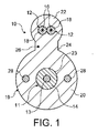
図1は、緩衝保護された光ファイバー11と2本の絶縁された導電体12が入った光ファイバー引込みケーブル(an optical fibre drop cable)10を示している。緩衝保護された光ファイバー11は、光ファイバー13と、そのファイバー13の表面を引っ掻きや磨耗から保護するプラスチック被覆14を備えている。プラスチック被覆は、例えばナイロン被覆でもよく、被覆で覆われたファイバーは、通常、直径が約1mmである。絶縁された導体12は、カラーコード化された電気絶縁被覆18内に封入された銅線16を備えているが、被覆18は、当業者周知の様に適していればどの様な材料で形成してもよい。通常、銅線は、直径が約0.4mmで、絶縁被覆の外径は通常約1.2mmである。ケーブルに接続された電話に電力供給するため、通常9ないし12ボルトを搬送している回路内で、一方の絶縁された導体12は生線として、他方の導体はニュートラル/アース線として機能している。一例として銅線を示してはいるが、アルミニウムなど他の適した導電材料を代わりに使用することもできる旨理解頂きたい。
For better understanding of the present invention, several embodiments of the present invention will be described below with reference to the drawings.
FIG. 1 shows an optical
光ファイバー11と導電体12は、外装19に収納されており、この外装は、光ファイバー13が入っている第1部分20と、第1部分から分離可能であり、かつ導電体12が入っている第2部分を備えている。光ファイバー11は、第1部分20に形成された通路23内に収納されており、その壁が、光ファイバーとその長さに亘って円周状に係合する通路を画定している。
The
外装部分20と22は、断面が略円形で互いに並んだ平行な関係にあり、略8の字の形状を形成している。両外装部分の間の接続点には、肉厚部、即ちウェブ24がある。ウェブには、第1外装部分及び第2外装部分の縦軸を通る面に対してオフセットし、それらの軸に対して実質的に平行にケーブルに沿って走る引き裂きコード(tear cord)、すなわち切り裂きコード(rip cord)26が入っている。切り裂きコード26は、引き裂き力を加えた際に、ウェブ24を切り裂いて第1外装部分と第2外装部分を分離できるだけの強さがあれば、どの様な材料で製作してもよい。切り裂きコードに適した材料の1つは、高強度Terylene(TN)の糸である。外装19は、適していれば、ポリエチレン、MDPE、HDPE、又はナイロンのような、どの様な被覆材料で製作してもよい。代表的には、外装の第1部分20の直径は約8mmであり、2つの外装部分を合わせた高さは約12mmである。
The
外装の第1部分19には、光ファイバー11に隣接して配置された強化部材28の形態をした強化装置が設けられている。強化部材28は、光ファイバー11の各側に1つずつ平行に間隔を空けた関係で配置され、外装の第1部分20に封入されている。図面に示すように、強化部材は、外装部分20、22の各縦軸を通る面に垂直で且つ外装の第1部分20の縦軸を通る面内に配置されるのが望ましい。強化部材28は、断面が実質的に円形であり外装の第1部分20の縦軸に概ね平行に伸びている。
The
強化部材は、ガラス強化プラスチック(GRP)のような誘電性材料で作るのが望ましいが、ガラス糸を使っても同様の利点が得られる。好ましくはないが、他の材料としてアラミド繊維を挙げることができる。誘電性材料が好ましいが、金属の強化材料を使用してもよい。GRP強化材料は、この材料が光ファイバーと同様の熱膨張係数を有しており、熱の影響により強化部材の長さが変化しても光ファイバーに伝わる力が増すことはないことから、好ましい材料である。ガラス糸にも同様の利点がある。アラミド繊維及び金属材料のような材料は、光ファイバーとは熱膨張係数が異なるので、これらの材料を使用する場合は、光ファイバーとは別様に膨張又は収縮することを考慮し、それによって光ファイバー13に悪影響を及ぼす荷重が確実に掛からないようにすることを考慮すべきである。
The reinforcing member is preferably made of a dielectric material such as glass reinforced plastic (GRP), but similar advantages are obtained using glass yarn. Although not preferred, other materials include aramid fibers. Although dielectric materials are preferred, metal reinforcement materials may be used. The GRP reinforced material has a thermal expansion coefficient similar to that of the optical fiber, and the force transmitted to the optical fiber does not increase even if the length of the reinforcing member changes due to the influence of heat. is there. Glass yarn has similar advantages. Materials such as aramid fibers and metal materials have different coefficients of thermal expansion from optical fibers, so when these materials are used, it is considered that they will expand or contract differently from optical fibers, thereby creating
GRP、ガラス糸、又はアラミド繊維のような電気的に非伝導性の材料で強化部材を作ることにより、更なる利点が得られる。撚った鋼のような導電性材料で強化部材を作る場合は、電気絶縁のために外装の直径を大きくする必要がある。非導電性強化部材を使用する場合は、あらゆる耐電圧要件を満たすために外装の第1部分20の外装肉厚を増しておく必要は無い。従って、外装の第1部分の直径を小さくすることができ、その結果ケーブルに対する氷や風による荷重の影響が小さくなる。非導電性強化部材を使用することにより、外装の第1部分19の直径は、外装が電気絶縁性を備えることを求められる場合に比較して、2mmも小さくすることができる。
A further advantage is obtained by making the reinforcing member from an electrically non-conductive material such as GRP, glass yarn, or aramid fiber. When a reinforcing member is made of a conductive material such as twisted steel, it is necessary to increase the diameter of the exterior for electrical insulation. When the non-conductive reinforcing member is used, it is not necessary to increase the outer wall thickness of the outer
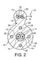
図2に示す光ファイバー引込みケーブル40は、光学引込み線10に対して単独で又は組合わせて加えられる変更を示している。第1の変更例では、強化部材28が更に2つ追加されている。光ファイバーケーブル40の4つの強化部材28は、共通のピッチ円上に90度間隔で配置され、外装の第1部分20及び第2部分22の縦軸を通過する面が2つの強化部材の縦軸を通過し、その面に垂直な第2面が他の2つの強化部材の縦軸を通過するように配置されている。第2の変更例では、2本の光ファイバー11が設けられている。図示のように、光ファイバー11は、円形通路44内にゆるく収納されている。しかしながら、外装の第1部分20は、単一の通路を形成するようにしてもよいし、図1の光ファイバーケーブル10と同じように光ファイバーを包み込む別々の通路を形成するようにしてもよい。
The optical fiber lead-in
図3は、光ファイバー11が、第1の外装部分20に形成された通路63内に含まれている中空プラスチックチューブ62の中にゆるく収納されている点で光ファイバー引込みケーブル10とは異なる光ファイバー引込みケーブル60を示している。このチューブの中には2つ以上の光ファイバーを入れることができるが、図では1つしか示していない。
FIG. 3 shows an optical fiber lead-in cable that differs from the optical fiber lead-in
図3に示す光ファイバー引込み線60に対して可能な変更(図示せず)には、チューブ62から光ファイバー11を省くことが含まれる。その場合は、光ファイバー引込みケーブルの敷設後、1つ又は複数のファイバー11がチューブの中に吹き込まれる。吹き込みファイバー法により敷設される光ファイバーは、例えば、EP−A−0345968号、EP−A−0521710号、又はEP−A−0646818号に開示されている形態を取ってもよいし、EP−A−0108590号に記載されている処理のような既知の吹き込み処理によりチューブ62内に導入してもよい。吹き込みファイバー敷設の場合、チューブ62は、US4952021号に開示されているように、内周面に炭素を充填し伝導率を高めたポリエチレンで作ってもよい。吹き込みファイバー敷設には、光ファイバーがケーブル吊り下げ時に発生する応力を受けないという利点がある。
Possible changes (not shown) to the optical fiber lead-in
光ファイバー引込みケーブル10、40、60に対する別の可能な変更(図示せず)には、強化部材28を、外装の第1部分20に入れられた強化スリーブの形を取る強化配置に代えることが含まれる。スリーブは、アラミド繊維のような非導電性材料で作るのが望ましい。しかしながら、スリーブは、鋼のような金属材料の撚り線で作ってもよい。このようなスリーブの繊維又は撚り線は、光ファイバー(11)及び/又はチューブ62並びに導電体12に2方向から螺旋状に巻きつける、いわゆるSZ巻きであるのが望ましい。
Another possible modification (not shown) to the fiber optic lead-in
図4は、光ファイバー引込みケーブル10、40、60の何れかを含む引込み線設備100を示している。説明を分かり易くするために、光ファイバー引込み線10を含む設備の場合だけについて参照する。
FIG. 4 shows a lead-in
引込み線設備100は、顧客の家屋まで走る電気通信線に対する接続を分配する配電装置が中に入ったハウジング101を含んでいる。ハウジングは、既知のファイバー地下ケーブル48のようなマルチファイバー・光ファイバーケーブル102で、交換局から配線されている。10本の電気通信線104と接続するに十分なファイバーを備えたマルチファイバー・光ファイバーケーブル103(シングルファイバー回路の場合ファイバー10本、ツインファイバー回路の場合ファイバー20本)は、ハウジング101から、近傍の電柱106の接続ボックス又はマニホールド105に伸びている。更に、参照番号103は、9ないし12ボルトの電圧をマニホールドに導電するための導電体を示している。
The lead-in
電気通信線104は、マニホールド105から、建物107のような顧客の家屋まで走っている。図面では、1本はマニホールドの右方向に伸びて建物107に到り、もう1本はマニホールドの左側に伸びる、2本の電気通信線104を示している。先に述べたように、光ファイバーケーブル103には、10本の電気通信線104と接続するのに十分な光ファイバーが入っており、従ってマニホールド105からは10本の別々の電気通信線が伸びている。
The
電気通信線104はそれぞれ、電柱106と建物107に取り付けられた各接続ボックス108で端と端が接続されている、長さを有する複数の光ファイバー引込みケーブル10を含んでいる。所定長さのケーブル10は、固定装置110で電柱106に接続されている。図面では、電柱は2本しか示していないが、実際には、マニホールド105と顧客家屋との間の途中のケーブルを支えるのに必要な数の電柱がある。通常は、電柱間の間隔は約200フィート(61メートル)であるが、100メートルまで伸ばしてもよい。
Each
図5に分かり易く示すように、各固定装置110は、2つの端部114、116を有するよう二重に折り曲げられ細長部材112を備えており、二重になった部分は、外装の第1部分20の回りに同じように螺旋状に巻きつけられ、折り曲げ部分、即ちループ118が両端部分を接続している。固定装置110は、更に、フック状の両端部を有する引張り接続部材120を備えており、一方の端部はループ118と係合し、他方の端部は電柱106に固定された電柱リング122と係合している。引張り接続部材120は、隣り合った電柱106上の固定装置の間のケーブル10の張力を調整するための手段(図示せず)を含んでいてもよい。その場合、引張り接続部材は2つの部分を備え、各部分は、フック状の端部分から離れた端部にねじが切られ、ナットの回転により引っ張り接続部材を長くしたり短くしたりできるようにナットで相互接続される。
As clearly shown in FIG. 5, each fixing
図5に示すように、細長部材112の端部分114、116を、外装の第1部分20の回りに巻きつけることができるようにするため、導電体12が入った第2部分22は、第1部分19から分離されている。この分離は、光ファイバーケーブル10の隣接する端部の切り裂きコード26の自由端にアクセスし、これを使って適した距離だけウェブ24を切り裂くことで容易に行える。図面中、破断部は、外装の第1部分19の分離された部分に、単にループ118と引張り接続部材120を分かり易く示すために示されている。
As shown in FIG. 5, in order to allow the
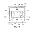
図6に概略的に示すように、接続ボックス108は、カバープレート(図示せず)を取り外すとアクセスできる中空の内部130を有している。ボックスの各側にはケーブル10の端部の入口点として機能するケーブル10用の開口部132が設けられている。分離された外装部分を個別に受け入れるために、単一の開口部132に代えて、対になった開口部を設けてもよい。接続ボックス108は、スクリュー133の様な適した手段で電柱106に固定される。各ボックス内には、押し込み嵌合コネクタ器具又は装置134が収納されており、これでケーブル10の両端がボックス内に固定される。押し込み嵌合コネクタ器具134は、適していればどの様な既知の押し込み嵌合技術を利用してもよく、2つの押し込み嵌合接続点135が各ケーブル端用に1つずつ間を空けて配置されている。
As shown schematically in FIG. 6, the
押し込み嵌合接続点135は、それぞれ図7に示すような押し込み嵌合コネクタ136のような押し込み嵌合コネクタ136を2つ有してもよい。各押し込み嵌合コネクタ136は、段付き貫通通路140を画定する本体138を備えている。円周方向に間隔を空けて配置され、半径方向内向きかつ軸方向内向きに伸びる複数の突起、すなわち、とげを有するリングを備えた把持手段142が、貫通通路140の両端から離れた位置にある、貫通通路の大径部分144内に収納されている。把持手段142は、金属製であるのが望ましいが、プラスチック材料製でもよく、とげは、外装部分20、22の端部を(図面では右側から)貫通通路140内へと挿入すると、半径方向外向きに撓むことができるが、ケーブルを挿入方向と反対の方向に引っぱると外装に食い込み、外装部分が接続点135から引き抜かれないように抵抗する。接続を切るのが望ましい場合には外装部分を引き抜けるように、コレット146が設けられてもよい。コレット146は、把持手段142に対し軸方向内向きに移動させると、貫通通路140内へ突き出て、とげと係合し、とげを半径方向外向きに撓ませ外装部分に対する把持を解いてその部分を引き抜けるようにする、円筒形の先端部148を有している。
The push-
それぞれの長さを有するケーブル10の隣接する端部の間の接続を接続ボックス108内で形成するために、各ケーブルのそれぞれの端部の分離された第1及び第2外装部分20、22は、開口部132を通して接続ボックス108の中空内部に送り込まれる。外装と強化部材28は、光ファイバー11と絶縁された導体12を露出させるために切り詰められ、外装部分の端部は、貫通通路140により画定されたショルダ150に外装の切り詰められた端部が当接するまで、それぞれの押し込み嵌合コネクタ136に押し込み嵌合される。この段階で、外装の第1部分及び第2部分の端部は、把持手段142のとげにより押し込み嵌合コネクタ136内に固定され、露出された光ファイバー11と絶縁された導体12は、貫通通路の内端152から接続ボックスの接続領域154まで突き出る。ここで、ケーブル端の導電体と光ファイバーは、適当な従来の手段で接続される。例えば、導体12は、絶縁被覆18を剥ぎ取って銅線16を露出させ、線の端を一緒にねじることにより接続されてもよい。代わりに、導線の端がスクリューで固定される端子ブロックを使用してもよい。
In order to form a connection in the
マニホールド105は、接続ボックス108と同様の構造であってもよい。マニホールド105は、光ファイバーケーブル103を送り込む追加の開口部と、マニホールドから10本の電気通信線104を送り出せるようにする10個の開口部132を保有している。電気通信線104の端部は、接続ボックス108の場合と同じように押し込み嵌合コネクタ136の様な押し込み嵌合コネクタ、又は何らかの他の適した手段で、マニホールド105内に固定することができる。同様に、マニホールド内に送り込まれる導電体の間、及び光ファイバー103の光ファイバーの間の接続は、適当な従来的手段により、導電体12と光ファイバー11により形成される。図4に示すように、電柱106の間に吊り下げられた所定長さの光ファイバー引込みケーブル10は、ケーブルの端から離間した位置でケーブルに固定された固定装置110により電柱に接続される。電柱の間に吊るされたケーブルに掛かる張力は、仮に手段が設けられている場合には、引張接続部材120の調整手段により、ケーブルを吊るした後で調整することができる。外装の第1部分の端部10E(図5)、並びに、固定装置110と接続ボックス108との間のその内容物は引っ張られない。
The manifold 105 may have the same structure as the
細長部材112の両端部114、116の螺旋巻きは、ケーブル10の張力が所定のレベルに達するか又はそれを超えると、外装が滑るような所定の力で外装を把持する様に作ることができる。ケーブルが滑ると、以前には張力の掛かっていなかった部分10Eに張力が掛かり、接続点136は、部分10Eの張力が、ケーブルの滑りを発生させる引張荷重より大きくない、望ましくは相当に低い第2の所定レベルに達すると、ケーブルが外れて、隣接する所定長さのケーブルとの接続を断つように設定されている。細長部材112がケーブルを滑らせる引張荷重は、ケーブルを破損させるのに要する荷重よりも低い荷重でケーブルが滑るように選択される。ケーブルの強度は、2KN程度の荷重が加わるとケーブルが破損し、細長部材112は1.2から1.5KN程度の荷重下でケーブルを滑らせるようにし、押し込み嵌合コネクタは170N程度の荷重でケーブル接続が破損するように作ることが期待されるが、上記荷重は例示を目的として示したものであり、限定を加えるものではない旨理解頂きたい。
The spiral turns of the
引込み線設備100では、端部10Eは、押し込み嵌合装置で接続ボックス106に固定されるように説明している。この構造は、簡潔さと装着の容易さの点で有利ではあるが、これに限定されるものではない。端部10Eは、端部10Eを所定の位置に保持するのに十分な安全性を提供し、正常な作動状態の間は何らの引張荷重も光ファイバー11と導体12の接合部に伝わらないようにすると同時に、高い信頼性で、固定装置110を通してケーブルを滑らせるのに要する荷重よりも小さい引張荷重で接続を断つことのできる、ばね負荷付のケーブルクランプの様な、何らかの適した手段で固定してもよい。
In the lead-in
電気通信線104を図3に示す光ファイバー引込みケーブル60を使って構成し、光ファイバーを吹き込み技法で敷設しようとする場合は、光ファイバーを吹き込む実質的に気密な通路を設ける必要がある。その場合、外装の第1部分20は、その端部を押し込み嵌合コネクタ136に押し込み嵌合すると、プラスチックチューブ62の切断された端部が貫通通路140の端部152から接続領域154内に突き出るように切り詰める。接続領域に突き出たチューブ62の端部は、次いで相互に接続して、光ファイバーに、その間に挿入された適した長さのチューブにより気密通路を提供することができる。代わりに、通路を形成する手段を、押し込み嵌合接続点135の間に設けて、チューブ62の端をその中に挿入すると光ファイバー用の連続した気密通路ができるような構造にしてもよい。
When the
光ファイバー引込みケーブルは、電気通信線の破損を制御するために引込み設備100で使用されるものとして説明しているが、これは基本的要件ではなく、このケーブルは適していれば、どの様な従来型の引込み設備に使用してもよい。
Although fiber optic lead-in cables are described as being used in lead-in
光ファイバー引込みケーブル10、40、60は、ケーブルを破損させるのに要する荷重よりも小さい荷重の下で電気通信線の破損を制御できる設備100のような設備に設置するのが基本的要件ではなく、そのような設備が有利であると理解されたい。これは、光ファイバー引込みケーブルを滑らせ、隣接する端部間の接続を断つような荷重を、ケーブルを破損させるのに要する荷重よりも小さくなるように選択できるからであり、これは、高速の車が通信線104に突っ込んできたり、木や他の構造物が上に落ちてきたりするような場合の有効な安全構造である。更に、所定長さの光ファイバー引込みケーブルとその隣接する所定長さの引込み線の間の接続は、そのような事象の時には切れるので、電気通信線への損傷は局所的なもので済み、これにより修理に要する時間と費用が軽減できる。更に、電気通信線は、所定の荷重が加えられると破損するように設計できるので、ケーブルをそうでない場合よりも遙かに強くして、ケーブルの中に入っている光ファイバーへの防護をより高めることができる。具体的には、ケーブルをより固くして、風力及び水分の凝結又は氷結などによる各種荷重の影響に対する耐性を高めることができる。
It is not a basic requirement that the fiber optic lead-in
既存の架空設備によりケーブルを支持する可能性とは逆に、光ファイバーに隣接する外装の第1部分に強化装置を設けること、又はケーブルに対して補助的に或いは外装の第2部分に強化装置を設けることには一般的に有利な点があると考えられる。その利点は、強化装置は、光ファイバーに近接して配置されているため、ケーブルの熱的性能と引張性能を直接制御し、光ファイバーに対する良好な防護を提供できることである。また、図4及び図5に示すような装置に設置するために外装部分を分離する場合も、外装部分を分離する領域の光ファイバーを防護するのに特別な手段は一切必要ないという利点もある。 Contrary to the possibility of supporting the cable with existing aerial installations, a reinforcement device is provided in the first part of the sheath adjacent to the optical fiber, or a reinforcement device is provided auxiliary to the cable or in the second part of the sheath It is generally considered that there are advantages to the provision. The advantage is that the strengthening device is located in close proximity to the optical fiber, so it can directly control the thermal and tensile performance of the cable and provide good protection against the optical fiber. Further, when the exterior part is separated for installation in an apparatus as shown in FIGS. 4 and 5, there is also an advantage that no special means is required to protect the optical fiber in the region where the exterior part is separated.
上記実施形態の光ファイバー引込みケーブルは、最終引込み線として架空設備に使用することを目的とした小数ファイバーケーブルである。このような小数ファイバーケーブルでは、光ファイバーの本数は1本又は2本であると考えられる。更に、導電体は、望ましくは9から12ボルトの低電圧しか搬送しないよう意図されているので、このためには導体は2本しか必要ない。 The optical fiber lead-in cable of the above embodiment is a fractional fiber cable intended for use in an aerial facility as a final lead-in line. In such a small fiber cable, the number of optical fibers is considered to be one or two. In addition, the conductor is preferably intended to carry only low voltages of 9 to 12 volts, so only two conductors are required for this purpose.
Claims (25)
前記ケーブルを前記吊り下げ設備内で支持するための強化装置を保有している第1部分と、前記第1部分から分離可能で、複数の導電体を保有している第2部分とを有する外装を備えており、
前記第1部分は光ファイバー用の少なくとも1つの通路を画定しているケーブル。 In fiber optic lead-in cables for hanging equipment,
An exterior having a first part having a strengthening device for supporting the cable in the suspension facility and a second part separable from the first part and having a plurality of conductors With
The cable wherein the first portion defines at least one passage for an optical fiber.
Applications Claiming Priority (2)
| Application Number | Priority Date | Filing Date | Title |
|---|---|---|---|
| EP01309727 | 2001-11-19 | ||
| PCT/GB2002/005153 WO2003044584A1 (en) | 2001-11-19 | 2002-11-15 | Optical fibre drop cables |
Publications (2)
| Publication Number | Publication Date |
|---|---|
| JP2005510027A true JP2005510027A (en) | 2005-04-14 |
| JP2005510027A5 JP2005510027A5 (en) | 2009-01-08 |
Family
ID=8182472
Family Applications (1)
| Application Number | Title | Priority Date | Filing Date |
|---|---|---|---|
| JP2003546157A Pending JP2005510027A (en) | 2001-11-19 | 2002-11-15 | Optical fiber lead-in cable |
Country Status (9)
| Country | Link |
|---|---|
| US (1) | US7106931B2 (en) |
| EP (1) | EP1446689B1 (en) |
| JP (1) | JP2005510027A (en) |
| CN (1) | CN1589417B (en) |
| AU (1) | AU2002339166B2 (en) |
| BR (2) | BR0206428A (en) |
| CA (1) | CA2467513C (en) |
| ES (1) | ES2401082T3 (en) |
| WO (1) | WO2003044584A1 (en) |
Cited By (1)
| Publication number | Priority date | Publication date | Assignee | Title |
|---|---|---|---|---|
| JP2016220319A (en) * | 2015-05-15 | 2016-12-22 | 日本電信電話株式会社 | Anchoring method for drop cable |
Families Citing this family (77)
| Publication number | Priority date | Publication date | Assignee | Title |
|---|---|---|---|---|
| US7783147B2 (en) | 2001-11-19 | 2010-08-24 | Prysmian Cables & Systems Limited | Optical fibre drop cables |
| WO2005098496A2 (en) * | 2004-03-26 | 2005-10-20 | Plain Sight Systems, Inc. | Method and apparatus for resonantly driving plasmon oscillations on nanowires |
| US7391943B2 (en) * | 2005-05-31 | 2008-06-24 | Corning Cable Systems Llc | Fiber optic cables that are separable for optical fiber access |
| US8472767B2 (en) | 2006-05-19 | 2013-06-25 | Corning Cable Systems Llc | Fiber optic cable and fiber optic cable assembly for wireless access |
| US20080011514A1 (en) * | 2006-07-14 | 2008-01-17 | Tenvera, Inc. | Optical Fiber Distribution Apparatus and Method |
| US20080013956A1 (en) * | 2006-07-14 | 2008-01-17 | Tenvera, Inc. | Provisioning of Services Via an Optical Fiber Network |
| US20080011990A1 (en) * | 2006-07-14 | 2008-01-17 | Tenvera, Inc. | Installation of Fiber Optic Cables |
| US20080013893A1 (en) * | 2006-07-14 | 2008-01-17 | Tenvera, Inc. | Optical Fiber Ferrule and Ferrule Receiver, and Method for Manufacturing the Same |
| US20080013907A1 (en) * | 2006-07-14 | 2008-01-17 | Tenvera, Inc. | Optical Fiber Blowing Device and Method |
| US20080013909A1 (en) * | 2006-07-14 | 2008-01-17 | Tenvera, Inc. | Modular Optical Fiber Network Interface |
| US20080013957A1 (en) * | 2006-07-14 | 2008-01-17 | Tenvera, Inc. | Service Aggregation Gateway |
| US7787823B2 (en) | 2006-09-15 | 2010-08-31 | Corning Cable Systems Llc | Radio-over-fiber (RoF) optical fiber cable system with transponder diversity and RoF wireless picocellular system using same |
| US7848654B2 (en) | 2006-09-28 | 2010-12-07 | Corning Cable Systems Llc | Radio-over-fiber (RoF) wireless picocellular system with combined picocells |
| US8873585B2 (en) | 2006-12-19 | 2014-10-28 | Corning Optical Communications Wireless Ltd | Distributed antenna system for MIMO technologies |
| US8111998B2 (en) | 2007-02-06 | 2012-02-07 | Corning Cable Systems Llc | Transponder systems and methods for radio-over-fiber (RoF) wireless picocellular systems |
| US20100054746A1 (en) * | 2007-07-24 | 2010-03-04 | Eric Raymond Logan | Multi-port accumulator for radio-over-fiber (RoF) wireless picocellular systems |
| US7409127B1 (en) * | 2007-09-28 | 2008-08-05 | Corning Cable Systems Llc | Fiber optic assemblies suitable for adding nodes to a communication network |
| US8175459B2 (en) | 2007-10-12 | 2012-05-08 | Corning Cable Systems Llc | Hybrid wireless/wired RoF transponder and hybrid RoF communication system using same |
| WO2009081376A2 (en) | 2007-12-20 | 2009-07-02 | Mobileaccess Networks Ltd. | Extending outdoor location based services and applications into enclosed areas |
| US9673904B2 (en) | 2009-02-03 | 2017-06-06 | Corning Optical Communications LLC | Optical fiber-based distributed antenna systems, components, and related methods for calibration thereof |
| WO2010090999A1 (en) | 2009-02-03 | 2010-08-12 | Corning Cable Systems Llc | Optical fiber-based distributed antenna systems, components, and related methods for monitoring and configuring thereof |
| EP2394379B1 (en) | 2009-02-03 | 2016-12-28 | Corning Optical Communications LLC | Optical fiber-based distributed antenna systems, components, and related methods for calibration thereof |
| US9360647B2 (en) * | 2009-02-06 | 2016-06-07 | Draka Comteq, B.V. | Central-tube cable with high-conductivity conductors encapsulated with high-dielectric-strength insulation |
| US8548330B2 (en) | 2009-07-31 | 2013-10-01 | Corning Cable Systems Llc | Sectorization in distributed antenna systems, and related components and methods |
| US8280259B2 (en) | 2009-11-13 | 2012-10-02 | Corning Cable Systems Llc | Radio-over-fiber (RoF) system for protocol-independent wired and/or wireless communication |
| CN102822709A (en) * | 2009-11-20 | 2012-12-12 | Adc电信公司 | Fiber optic cable assembly |
| US8275265B2 (en) | 2010-02-15 | 2012-09-25 | Corning Cable Systems Llc | Dynamic cell bonding (DCB) for radio-over-fiber (RoF)-based networks and communication systems and related methods |
| US20110268446A1 (en) | 2010-05-02 | 2011-11-03 | Cune William P | Providing digital data services in optical fiber-based distributed radio frequency (rf) communications systems, and related components and methods |
| US9525488B2 (en) | 2010-05-02 | 2016-12-20 | Corning Optical Communications LLC | Digital data services and/or power distribution in optical fiber-based distributed communications systems providing digital data and radio frequency (RF) communications services, and related components and methods |
| CN103119865A (en) | 2010-08-16 | 2013-05-22 | 康宁光缆系统有限责任公司 | Remote antenna clusters and related systems, components, and methods supporting digital data signal propagation between remote antenna units |
| US9252874B2 (en) | 2010-10-13 | 2016-02-02 | Ccs Technology, Inc | Power management for remote antenna units in distributed antenna systems |
| US20120145453A1 (en) * | 2010-12-14 | 2012-06-14 | General Cable Technologies Corporation | Power cable with microduct |
| WO2012115843A1 (en) | 2011-02-21 | 2012-08-30 | Corning Cable Systems Llc | Providing digital data services as electrical signals and radio-frequency (rf) communications over optical fiber in distributed communications systems, and related components and methods |
| CN103609146B (en) | 2011-04-29 | 2017-05-31 | 康宁光缆系统有限责任公司 | For increasing the radio frequency in distributing antenna system(RF)The system of power, method and apparatus |
| EP2702710A4 (en) | 2011-04-29 | 2014-10-29 | Corning Cable Sys Llc | Determining propagation delay of communications in distributed antenna systems, and related components, systems and methods |
| US9419321B2 (en) | 2011-08-12 | 2016-08-16 | Commscope Technologies Llc | Self-supporting stripline RF transmission cable |
| EP2832012A1 (en) | 2012-03-30 | 2015-02-04 | Corning Optical Communications LLC | Reducing location-dependent interference in distributed antenna systems operating in multiple-input, multiple-output (mimo) configuration, and related components, systems, and methods |
| EP2842245A1 (en) | 2012-04-25 | 2015-03-04 | Corning Optical Communications LLC | Distributed antenna system architectures |
| WO2014024192A1 (en) | 2012-08-07 | 2014-02-13 | Corning Mobile Access Ltd. | Distribution of time-division multiplexed (tdm) management services in a distributed antenna system, and related components, systems, and methods |
| US9455784B2 (en) | 2012-10-31 | 2016-09-27 | Corning Optical Communications Wireless Ltd | Deployable wireless infrastructures and methods of deploying wireless infrastructures |
| CN105308876B (en) | 2012-11-29 | 2018-06-22 | 康宁光电通信有限责任公司 | Remote unit antennas in distributing antenna system combines |
| US9647758B2 (en) | 2012-11-30 | 2017-05-09 | Corning Optical Communications Wireless Ltd | Cabling connectivity monitoring and verification |
| CH707360A1 (en) * | 2012-12-17 | 2014-06-30 | Alpine En Holding Ag | Telecommunication system and to appropriate telecommunications cable |
| WO2014197103A2 (en) | 2013-03-18 | 2014-12-11 | Adc Telecommunications, Inc. | Architecture for a wireless network |
| US9557505B2 (en) | 2013-03-18 | 2017-01-31 | Commscope Technologies Llc | Power and optical fiber interface |
| MX359326B (en) | 2013-05-14 | 2018-09-25 | Adc Telecommunications Inc | Power/fiber hybrid cable. |
| CN103325459A (en) * | 2013-05-31 | 2013-09-25 | 成都亨通光通信有限公司 | Photodetachment easily-branching type mixed cable in shape of Arabic number 8 |
| WO2014199384A1 (en) | 2013-06-12 | 2014-12-18 | Corning Optical Communications Wireless, Ltd. | Voltage controlled optical directional coupler |
| EP3008828B1 (en) | 2013-06-12 | 2017-08-09 | Corning Optical Communications Wireless Ltd. | Time-division duplexing (tdd) in distributed communications systems, including distributed antenna systems (dass) |
| US9247543B2 (en) | 2013-07-23 | 2016-01-26 | Corning Optical Communications Wireless Ltd | Monitoring non-supported wireless spectrum within coverage areas of distributed antenna systems (DASs) |
| US9661781B2 (en) | 2013-07-31 | 2017-05-23 | Corning Optical Communications Wireless Ltd | Remote units for distributed communication systems and related installation methods and apparatuses |
| US9385810B2 (en) | 2013-09-30 | 2016-07-05 | Corning Optical Communications Wireless Ltd | Connection mapping in distributed communication systems |
| US9178635B2 (en) | 2014-01-03 | 2015-11-03 | Corning Optical Communications Wireless Ltd | Separation of communication signal sub-bands in distributed antenna systems (DASs) to reduce interference |
| US9775123B2 (en) | 2014-03-28 | 2017-09-26 | Corning Optical Communications Wireless Ltd. | Individualized gain control of uplink paths in remote units in a distributed antenna system (DAS) based on individual remote unit contribution to combined uplink power |
| US9357551B2 (en) | 2014-05-30 | 2016-05-31 | Corning Optical Communications Wireless Ltd | Systems and methods for simultaneous sampling of serial digital data streams from multiple analog-to-digital converters (ADCS), including in distributed antenna systems |
| US9525472B2 (en) | 2014-07-30 | 2016-12-20 | Corning Incorporated | Reducing location-dependent destructive interference in distributed antenna systems (DASS) operating in multiple-input, multiple-output (MIMO) configuration, and related components, systems, and methods |
| US9730228B2 (en) | 2014-08-29 | 2017-08-08 | Corning Optical Communications Wireless Ltd | Individualized gain control of remote uplink band paths in a remote unit in a distributed antenna system (DAS), based on combined uplink power level in the remote unit |
| US9602210B2 (en) | 2014-09-24 | 2017-03-21 | Corning Optical Communications Wireless Ltd | Flexible head-end chassis supporting automatic identification and interconnection of radio interface modules and optical interface modules in an optical fiber-based distributed antenna system (DAS) |
| US10659163B2 (en) | 2014-09-25 | 2020-05-19 | Corning Optical Communications LLC | Supporting analog remote antenna units (RAUs) in digital distributed antenna systems (DASs) using analog RAU digital adaptors |
| US9420542B2 (en) | 2014-09-25 | 2016-08-16 | Corning Optical Communications Wireless Ltd | System-wide uplink band gain control in a distributed antenna system (DAS), based on per band gain control of remote uplink paths in remote units |
| WO2016071902A1 (en) | 2014-11-03 | 2016-05-12 | Corning Optical Communications Wireless Ltd. | Multi-band monopole planar antennas configured to facilitate improved radio frequency (rf) isolation in multiple-input multiple-output (mimo) antenna arrangement |
| WO2016075696A1 (en) | 2014-11-13 | 2016-05-19 | Corning Optical Communications Wireless Ltd. | Analog distributed antenna systems (dass) supporting distribution of digital communications signals interfaced from a digital signal source and analog radio frequency (rf) communications signals |
| US9729267B2 (en) | 2014-12-11 | 2017-08-08 | Corning Optical Communications Wireless Ltd | Multiplexing two separate optical links with the same wavelength using asymmetric combining and splitting |
| EP3235336A1 (en) | 2014-12-18 | 2017-10-25 | Corning Optical Communications Wireless Ltd. | Digital interface modules (dims) for flexibly distributing digital and/or analog communications signals in wide-area analog distributed antenna systems (dass) |
| WO2016098111A1 (en) | 2014-12-18 | 2016-06-23 | Corning Optical Communications Wireless Ltd. | Digital- analog interface modules (da!ms) for flexibly.distributing digital and/or analog communications signals in wide-area analog distributed antenna systems (dass) |
| US20160249365A1 (en) | 2015-02-19 | 2016-08-25 | Corning Optical Communications Wireless Ltd. | Offsetting unwanted downlink interference signals in an uplink path in a distributed antenna system (das) |
| US9681313B2 (en) | 2015-04-15 | 2017-06-13 | Corning Optical Communications Wireless Ltd | Optimizing remote antenna unit performance using an alternative data channel |
| CA2986474C (en) * | 2015-05-27 | 2022-11-01 | Prysmian S.P.A. | Aerial optical and electric cable assembly |
| US9948349B2 (en) | 2015-07-17 | 2018-04-17 | Corning Optical Communications Wireless Ltd | IOT automation and data collection system |
| US10560214B2 (en) | 2015-09-28 | 2020-02-11 | Corning Optical Communications LLC | Downlink and uplink communication path switching in a time-division duplex (TDD) distributed antenna system (DAS) |
| CN105375431B (en) * | 2015-12-10 | 2017-05-31 | 国网四川省电力公司电力科学研究院 | One kind communication lightning-protection system |
| US10236924B2 (en) | 2016-03-31 | 2019-03-19 | Corning Optical Communications Wireless Ltd | Reducing out-of-channel noise in a wireless distribution system (WDS) |
| EP3513231A1 (en) | 2016-09-14 | 2019-07-24 | Prysmian S.p.A. | Figure-of-eight cable |
| EP3539255A4 (en) | 2016-11-09 | 2020-05-27 | Commscope Inc. of North Carolina | Exchangeable powered infrastructure module |
| DE102018118450B3 (en) * | 2018-07-31 | 2020-01-30 | Lwl-Sachsenkabel Gmbh Spezialkabel Und Vernetzungstechnik | Junction box for fiber-optic distribution networks and method for installing a junction box |
| CN112461663B (en) * | 2020-11-27 | 2022-11-11 | 安徽长荣光纤光缆科技有限公司 | Optical fiber cable tensile deformation detection device |
| CN117392796B (en) * | 2023-12-11 | 2024-03-22 | 云南保利天同水下装备科技有限公司 | Partition detection method, partition detection system and defense detection assembly thereof |
Family Cites Families (25)
| Publication number | Priority date | Publication date | Assignee | Title |
|---|---|---|---|---|
| DE3037289C2 (en) | 1980-10-02 | 1982-10-28 | Siemens AG, 1000 Berlin und 8000 München | Optical aerial cable |
| GB2104304B (en) | 1981-06-16 | 1985-01-16 | Bicc Plc | An improved overhead electric transmission or distribution system |
| ATE134046T1 (en) | 1982-11-08 | 1996-02-15 | British Telecomm | OPTICAL CABLE |
| JPS59226413A (en) * | 1983-06-06 | 1984-12-19 | 住友電気工業株式会社 | Optical composite cable |
| FR2543729B1 (en) * | 1983-03-30 | 1985-12-27 | Cables De Lyon Geoffroy Delore | COMPOSITE CABLE FOR TRANSMISSION OF HIGH FREQUENCY SIGNALS AND OPTICAL SIGNALS |
| DE3522694A1 (en) | 1985-06-25 | 1987-01-08 | Kabelmetal Electro Gmbh | Cable for the transmission of signals |
| JPS6267505A (en) | 1985-09-20 | 1987-03-27 | Furukawa Electric Co Ltd:The | Method for laying optical cable to aerial |
| US4952021A (en) * | 1988-05-18 | 1990-08-28 | Sumitomo Electric Industries Ltd. | Pressure transporting system |
| GB8911959D0 (en) | 1988-05-28 | 1989-07-12 | Ici Plc | Coated optical fibres |
| NZ231613A (en) | 1988-12-01 | 1992-04-28 | British Telecomm | Drop cable; carried line in duct and supported by cable |
| GB8917347D0 (en) | 1989-07-28 | 1989-09-13 | Bicc Plc | Overhead electric and optical transmission systems |
| US5189718A (en) * | 1991-04-02 | 1993-02-23 | Siecor Corporation | Composite cable containing light waveguides and electrical conductors |
| KR100303720B1 (en) | 1991-07-01 | 2001-11-22 | 내쉬 로저 윌리엄 | Optical fiber and its manufacturing method |
| CA2090053C (en) * | 1992-03-24 | 1997-10-28 | Lawrence Russell Dunn | Hybrid communications cable for enhancement of transmission capability |
| GB2270992B (en) | 1992-08-04 | 1995-12-20 | Pirelli General Plc | Cables having electrical conductors and optical fibres |
| GB2282897B (en) | 1993-10-01 | 1996-10-23 | Pirelli General Plc | Optical fibre assembly with coating having projecting particulate material for blown installation |
| US5469523A (en) * | 1994-06-10 | 1995-11-21 | Commscope, Inc. | Composite fiber optic and electrical cable and associated fabrication method |
| GB2308752B (en) * | 1995-12-22 | 1999-12-29 | Pirelli General Plc | Suspended line for an optical fibre unit |
| DE19641616B4 (en) * | 1996-10-09 | 2007-07-19 | CCS Technology, Inc., Wilmington | Communication cable with strain relief elements attached in the area of the outer jacket |
| US6563990B1 (en) * | 1998-06-22 | 2003-05-13 | Corning Cable Systems, Llc | Self-supporting cables and an apparatus and methods for making the same |
| US6195487B1 (en) | 1998-06-30 | 2001-02-27 | Pirelli Cable Corporation | Composite cable for access networks |
| US6363192B1 (en) * | 1998-12-23 | 2002-03-26 | Corning Cable Systems Llc | Composite cable units |
| US6236789B1 (en) * | 1999-12-22 | 2001-05-22 | Pirelli Cables And Systems Llc | Composite cable for access networks |
| US6545222B2 (en) * | 2000-01-11 | 2003-04-08 | Sumitomo Electric Industries, Ltd. | Cable, and method for removing sheath at intermediate part of cable |
| US7783147B2 (en) | 2001-11-19 | 2010-08-24 | Prysmian Cables & Systems Limited | Optical fibre drop cables |
-
2002
- 2002-11-15 WO PCT/GB2002/005153 patent/WO2003044584A1/en active Application Filing
- 2002-11-15 EP EP02777542A patent/EP1446689B1/en not_active Expired - Lifetime
- 2002-11-15 CA CA2467513A patent/CA2467513C/en not_active Expired - Fee Related
- 2002-11-15 US US10/495,980 patent/US7106931B2/en not_active Expired - Lifetime
- 2002-11-15 CN CN028229363A patent/CN1589417B/en not_active Expired - Fee Related
- 2002-11-15 ES ES02777542T patent/ES2401082T3/en not_active Expired - Lifetime
- 2002-11-15 AU AU2002339166A patent/AU2002339166B2/en not_active Ceased
- 2002-11-15 BR BR0206428-6A patent/BR0206428A/en not_active IP Right Cessation
- 2002-11-15 JP JP2003546157A patent/JP2005510027A/en active Pending
- 2002-11-15 BR BRPI0206428-6A patent/BRPI0206428B1/en unknown
Cited By (1)
| Publication number | Priority date | Publication date | Assignee | Title |
|---|---|---|---|---|
| JP2016220319A (en) * | 2015-05-15 | 2016-12-22 | 日本電信電話株式会社 | Anchoring method for drop cable |
Also Published As
| Publication number | Publication date |
|---|---|
| CN1589417B (en) | 2012-05-30 |
| WO2003044584A1 (en) | 2003-05-30 |
| CA2467513C (en) | 2011-09-27 |
| CN1589417A (en) | 2005-03-02 |
| BR0206428A (en) | 2003-12-23 |
| AU2002339166A1 (en) | 2003-06-10 |
| BRPI0206428B1 (en) | 2017-11-28 |
| AU2002339166B2 (en) | 2009-01-29 |
| US20050002622A1 (en) | 2005-01-06 |
| EP1446689B1 (en) | 2013-01-30 |
| ES2401082T3 (en) | 2013-04-16 |
| US7106931B2 (en) | 2006-09-12 |
| EP1446689A1 (en) | 2004-08-18 |
| CA2467513A1 (en) | 2003-05-30 |
Similar Documents
| Publication | Publication Date | Title |
|---|---|---|
| JP2005510027A (en) | Optical fiber lead-in cable | |
| US7783147B2 (en) | Optical fibre drop cables | |
| JP2005510027A5 (en) | ||
| JP2006058892A (en) | Optical fiber cable | |
| US4820012A (en) | Electric wire | |
| JPS6193514A (en) | Mechanical connector for electricity and light transmission system set overhead | |
| CZ283964B6 (en) | Terrestrial optical transmission systems and installation process thereof | |
| US10833494B2 (en) | Apparatus, method and system for electrical interconnection | |
| CN113949028B (en) | Optical fiber composite overhead insulated cable laying and connecting assembly for metropolitan area distribution network | |
| EP3451037A1 (en) | Method for gripping optical fiber cable, and optical fiber cable gripping tool | |
| JP2008129170A (en) | Optical fiber cable, optical fiber cable system using the same, and method of laying optical fiber cable | |
| EP3304155B1 (en) | Aerial optical and electric cable assembly | |
| KR20110039837A (en) | Optical fiber cable | |
| WO2002057833A1 (en) | A method of routing fibre optic core and a fibre optic core distribution network produced thereby | |
| CN216489655U (en) | Optical fiber composite overhead insulated cable laying and connecting assembly for metropolitan area power distribution network | |
| US20240027718A1 (en) | Supporting and routing drop lines from an all-dielectric selfsupporting (adss) fiber optic trunk cable | |
| RU136900U1 (en) | FIBER OPTICAL CABLE NAVY | |
| CN211578458U (en) | Ultra-light photoelectric composite cable | |
| KR100342592B1 (en) | Tight bound fluorescent cable | |
| CN113889303A (en) | Photoelectric hybrid cable for smart city road pole and matched construction method | |
| JPS60162203A (en) | Optical fiber taking-in structure of optical fiber compound overhead power transmission line | |
| JP2001216851A (en) | Composite electrical wire | |
| KR20000047115A (en) | Tightly bound optical cable | |
| JPH053614A (en) | Extending method for light-electric power composite cable | |
| JP2001251746A (en) | Stringing method for drop cable |
Legal Events
| Date | Code | Title | Description |
|---|---|---|---|
| A621 | Written request for application examination |
Free format text: JAPANESE INTERMEDIATE CODE: A621 Effective date: 20050930 |
|
| A131 | Notification of reasons for refusal |
Free format text: JAPANESE INTERMEDIATE CODE: A131 Effective date: 20080514 |
|
| A601 | Written request for extension of time |
Free format text: JAPANESE INTERMEDIATE CODE: A601 Effective date: 20080814 |
|
| A602 | Written permission of extension of time |
Free format text: JAPANESE INTERMEDIATE CODE: A602 Effective date: 20080821 |
|
| A524 | Written submission of copy of amendment under section 19 (pct) |
Free format text: JAPANESE INTERMEDIATE CODE: A524 Effective date: 20081113 |
|
| A02 | Decision of refusal |
Free format text: JAPANESE INTERMEDIATE CODE: A02 Effective date: 20100302 |