JP2005509357A - Method for link adaptation processing and transmission power control related to applications - Google Patents
Method for link adaptation processing and transmission power control related to applications Download PDFInfo
- Publication number
- JP2005509357A JP2005509357A JP2003543214A JP2003543214A JP2005509357A JP 2005509357 A JP2005509357 A JP 2005509357A JP 2003543214 A JP2003543214 A JP 2003543214A JP 2003543214 A JP2003543214 A JP 2003543214A JP 2005509357 A JP2005509357 A JP 2005509357A
- Authority
- JP
- Japan
- Prior art keywords
- node
- link
- data
- frame
- mode
- Prior art date
- Legal status (The legal status is an assumption and is not a legal conclusion. Google has not performed a legal analysis and makes no representation as to the accuracy of the status listed.)
- Granted
Links
Images


Classifications
-
- H—ELECTRICITY
- H04—ELECTRIC COMMUNICATION TECHNIQUE
- H04L—TRANSMISSION OF DIGITAL INFORMATION, e.g. TELEGRAPHIC COMMUNICATION
- H04L1/00—Arrangements for detecting or preventing errors in the information received
- H04L1/0001—Systems modifying transmission characteristics according to link quality, e.g. power backoff
- H04L1/0023—Systems modifying transmission characteristics according to link quality, e.g. power backoff characterised by the signalling
- H04L1/0026—Transmission of channel quality indication
-
- A—HUMAN NECESSITIES
- A01—AGRICULTURE; FORESTRY; ANIMAL HUSBANDRY; HUNTING; TRAPPING; FISHING
- A01D—HARVESTING; MOWING
- A01D34/00—Mowers; Mowing apparatus of harvesters
- A01D34/001—Accessories not otherwise provided for
- A01D34/005—Mulching means
-
- H—ELECTRICITY
- H04—ELECTRIC COMMUNICATION TECHNIQUE
- H04L—TRANSMISSION OF DIGITAL INFORMATION, e.g. TELEGRAPHIC COMMUNICATION
- H04L1/00—Arrangements for detecting or preventing errors in the information received
- H04L1/0001—Systems modifying transmission characteristics according to link quality, e.g. power backoff
- H04L1/0023—Systems modifying transmission characteristics according to link quality, e.g. power backoff characterised by the signalling
-
- A—HUMAN NECESSITIES
- A01—AGRICULTURE; FORESTRY; ANIMAL HUSBANDRY; HUNTING; TRAPPING; FISHING
- A01D—HARVESTING; MOWING
- A01D2101/00—Lawn-mowers
-
- H—ELECTRICITY
- H04—ELECTRIC COMMUNICATION TECHNIQUE
- H04L—TRANSMISSION OF DIGITAL INFORMATION, e.g. TELEGRAPHIC COMMUNICATION
- H04L1/00—Arrangements for detecting or preventing errors in the information received
- H04L1/0001—Systems modifying transmission characteristics according to link quality, e.g. power backoff
- H04L1/0009—Systems modifying transmission characteristics according to link quality, e.g. power backoff by adapting the channel coding
Landscapes
- Engineering & Computer Science (AREA)
- Quality & Reliability (AREA)
- Computer Networks & Wireless Communication (AREA)
- Signal Processing (AREA)
- Life Sciences & Earth Sciences (AREA)
- Environmental Sciences (AREA)
- Mobile Radio Communication Systems (AREA)
- Small-Scale Networks (AREA)
- Transceivers (AREA)
- Detection And Prevention Of Errors In Transmission (AREA)
- Temperature-Responsive Valves (AREA)
- Harvester Elements (AREA)
Abstract
Description
本願は、2001年11月8日に提出された米国特許仮出願第60/344,610号について優先権を主張するとともに、その開示のすべてをここに参照により取り入れる。 This application claims priority to US Provisional Application No. 60 / 344,610, filed Nov. 8, 2001, the entire disclosure of which is hereby incorporated by reference.
本発明は、リンク適応処理に係り、とりわけ、通信するノード間でリンクモードの情報を転送することなくリンクを適応させる方法に関連する。 The present invention relates to link adaptation processing, and more particularly to a method for adapting a link without transferring link mode information between communicating nodes.
IEEE802.11のワイヤレスLAN(WLAN)標準規格は1997年に策定され、様々なノード間でワイヤレスLANによる通信が可能となった。IEEE802.11標準規格は、OFDM(直交周波数分割多重)方式をベースとした新しい物理層を用いて拡張されている。また、高度のQAM(直交振幅変調方式)や種々の畳み込み符号処理を用いて、7つの異なるデータレートを実現している。2.4GHzの周波数帯向けに設計された類似の規格であるIEEE802.11bも規格化されており、この規格でも4つの異なるデータレートを提供している。 The IEEE 802.11 wireless LAN (WLAN) standard was established in 1997, and wireless LAN communication between various nodes became possible. The IEEE 802.11 standard has been extended with a new physical layer based on the OFDM (Orthogonal Frequency Division Multiplexing) scheme. In addition, seven different data rates are realized using advanced QAM (Quadrature Amplitude Modulation) and various convolutional code processes. IEEE 802.11b, a similar standard designed for the 2.4 GHz frequency band, has also been standardized, and this standard also provides four different data rates.
これらの標準規格や現存するすべてのリンク適応アルゴリズムのいずれもが、リンク適応制御メッセージを送信するための交換メカニズムを定義してはいない。リンク適応メッセージのための交換メカニズムが欠如しているので、IEEE802.11の性能について限界が生じている。正しいリンク適応が選択されているかどうかに関する間接的な示唆に、設計者らは頼らなければならない。これらの例には、ある種の受領通知が有るか無いかが含まれる。従って、明瞭なリンクモードのシグナリングを必要としないリンク適応を制御する方法が必要とされている。 None of these standards or all existing link adaptation algorithms define an exchange mechanism for sending link adaptation control messages. The lack of an exchange mechanism for link adaptation messages has created a limit on the performance of IEEE 802.11. Designers must rely on indirect suggestions as to whether the correct link adaptation has been chosen. These examples include the presence or absence of certain types of receipt notifications. Therefore, there is a need for a method for controlling link adaptation that does not require explicit link mode signaling.
本発明は、第1のノードと第2のノードとの間にあるリンクを介して情報を転送するシステム及び方法に関する上述の問題及び他の問題を克服しようとするものである。第1のノードから第2のノードへとフレームが送信される。当該フレームにはリンクデータが含まれている。リンクデータは、将来の転送のためのリンクモードを第2のノードが決定するのに役立つものである。当該フレームを第2のノードが受信すると、第2のノードは、当該フレームに含まれていたリンクデータを使用して、第2のノードから第1のノードへのリンクモードの決定を実行する。決定されたリンクモードを使用して、第2のノードから第1のノードへの送信が実行される。 The present invention seeks to overcome the above and other problems associated with systems and methods for transferring information over a link between a first node and a second node. A frame is transmitted from the first node to the second node. The frame includes link data. The link data is useful for the second node to determine the link mode for future transfers. When the second node receives the frame, the second node performs link mode determination from the second node to the first node using the link data included in the frame. A transmission from the second node to the first node is performed using the determined link mode.
添付の図面は、本発明の実施形態を図解しており、また本発明の原理を説明するための記述が含まれている。さらに、当該図面は、本発明の理解を深めるために提供され、またこの明細書の一部を構成するとともに明細書に取り入れられているものとする。 The accompanying drawings illustrate embodiments of the invention and include descriptions to explain the principles of the invention. Further, the drawings are provided to enhance the understanding of the present invention, and constitute a part of this specification and are incorporated in the specification.
添付図面のうち、とりわけ図1を参照する。図1には、伝統的なリンク適応処理の例が示されている。ノードAは、10において、ノードBが受信品質を決定できるようにするためのフレームを送信する。ノードBは、ある種のアルゴリズムまたは処理15において、この情報を使用する。このアルゴリズムまたは処理15は、ノードAからノードBへの通信用のリンクモードについて最適なものを選択するものである。続いて、ノードBは、ノードAに対し、推奨されるリンク適応(リンクアダプテーション:LA)モードについての通知を送信する。ノードAは、推奨されているリンクモードを使用して、後続の送信25を実行する。このプロシージャは、後続の通信のために繰り返し利用され、これによって、リンクの状態の変化に対し連続的に適応することが可能となる。このプロシージャは、閉ループ型の送信電力制御に類似しており、当該電力制御回路に統合してもよい。
In particular, reference is made to FIG. 1 of the accompanying drawings. FIG. 1 shows an example of a traditional link adaptation process. Node A transmits a frame at 10 to allow node B to determine the reception quality. Node B uses this information in certain algorithms or
いくつかの無線システムにおいて、ノードの1つはアクセスネットワークへと物理的にアタッチされていてもよい。アクセスネットワークが、あるリンクモードを使用するという決定をしてもよい。ここで、他のノードらはリンクモードについての推奨情報を提供するだけであってもよいし、あるいは測定報告を送信するだけであってもよい。その結果、いささか非対称性が生じる。これは図1からは明瞭ではないが、ノードAとノードBとが互いに均等ではないからである。このタイプのシステムでの主な問題は、IEEE802.11用の詳細なシグナリング方法が定義されていないことである。それゆえ、この方法は、リンク適応シグナリングを用いて、標準規格を拡張できる場合にしか適用できない。 In some wireless systems, one of the nodes may be physically attached to the access network. The access network may make the decision to use a certain link mode. Here, the other nodes may only provide recommendation information about the link mode, or may only send a measurement report. The result is some asymmetry. Although this is not clear from FIG. 1, node A and node B are not equal to each other. The main problem with this type of system is that the detailed signaling method for IEEE 802.11 is not defined. This method is therefore only applicable when the standard can be extended using link adaptive signaling.
IEEE802.11について考えられるリンク適応方式の一つは、間接的なフィードバックを使用することである。もちろんこの方式も、明確なリンク適応のフィードバックメカニズムが欠如している。間接的なフィードバックは、受信確認通知が到着しているか未着であるかを利用することによって適用可能である。リンクモードは、応答の関数として上昇または下降する。しかしながら、このアプローチは、適当なレートが見つかるまで少々時間がかかり、それを我慢することを通信に強いるものである。動作点を決定するようにフレームエラーは意図的に導かなければならないので、レートを増加/減少させる方法は、あまり効率的ではない。 One possible link adaptation scheme for IEEE 802.11 is to use indirect feedback. Of course, this method also lacks a clear link adaptation feedback mechanism. Indirect feedback can be applied by using whether the reception confirmation notification has arrived or has not arrived. The link mode rises or falls as a function of response. However, this approach takes some time to find a suitable rate and forces the communication to endure it. Since frame errors must be deliberately introduced to determine the operating point, the method of increasing / decreasing the rate is not very efficient.
エンティティ間で情報を送信する必要のある閉ループシステムにおいて実装される伝統的なリンク適応システムの方法には、リンク適応用のシグナリング方式が必要とされるといった問題が内在している。図2を参照すると、本発明によれば開ループ型のリンク適応アプローチが提案されている。多くの無線システムで利用可能なチャネルの相互性を利用することによって、これは実現される。しかしながら、この方式を実現するには追加の情報が必要となる。まずフレームが送信されるときの送信電力に関する情報が提供されなければならない。また、受信ノードにおける干渉レベルも提供されなければならない(好ましくは、干渉レベルフィールドにおいて示唆されなければならない。)。干渉レベルは、スペクトラム分布によって例示されてもよい。 The problem with traditional link adaptation systems implemented in closed loop systems that need to transmit information between entities is that a signaling scheme for link adaptation is required. Referring to FIG. 2, an open loop link adaptation approach is proposed according to the present invention. This is achieved by taking advantage of the channel reciprocity available in many wireless systems. However, additional information is required to implement this scheme. First, information on transmission power when a frame is transmitted must be provided. The interference level at the receiving node must also be provided (preferably should be suggested in the interference level field). The interference level may be exemplified by a spectrum distribution.
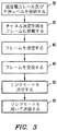
図2に示されているシーケンスと図3に示されているフローチャートに関連する方法について参照する。初めに、ステップ30において、送信電力レベルとノードAの干渉レベルとが、ノードAからノードBへと送信されるフレーム中に記憶される。さらに、ステップ35において、チャネルの決定を可能にするいくつかの手段が当該フレームに含められる。チャネルを推定する方法は二つあり、いわゆるパイロットシーケンス(これは、パイロット、パイロットシンボル、チャネル推定シーケンス/シンボル、トレーニングシーケンス/シンボルと呼ばれることがある。)、またはいわゆるブラインドチャネル推定を通して実行する方法である。ブラインドチャネル推定はそれほど一般的な方法ではないが、特定のパイロットシーケンスに頼る必要がない。その代わりに、データ搬送シンボル(または類似のもの)と、使用されている変調方式についてのある種の属性とを使用する。例えば、許容されている変調方式の振幅もしくは位相についての情報は、チャネルの情報を決定するために使用することができる。パイロットシーケンスの場合は、トレーニングシーケンスについての情報を保持している受信機は、良いチャネル推定を実行できる。システムを識別できるようにするため、あるシステムと他のシステムとではパイロットシーケンスが異なり、また変調方式を識別するためにある変調方式と他の変調方式とではパイロットシーケンスが異なるように設計される。例えば、IEEE802.11aで使用されているパイロットシーケンスは、標準規格において定められている。ステップ40において、ノードAはノードBへとフレームを送信し、ステップS45において当該フレームがノードBによって受信される。
Reference is made to the method associated with the sequence shown in FIG. 2 and the flowchart shown in FIG. Initially, in
IEEE802.11のプロトコルでは、例えば、フレームは、アクセスポイントからステーション(STA)へと発行されたCF−POLLフレームとすることができる。ノードAは、使用されている送信電力と望ましい受信電力とを同一のCF−POLLフレームに入れて伝送しうる。後者は、ノードAにて観測される干渉レベルと受信電力のレベルに依存している。 In the IEEE 802.11 protocol, for example, the frame may be a CF-POLL frame issued from an access point to a station (STA). Node A can transmit the used transmission power and the desired reception power in the same CF-POLL frame. The latter depends on the interference level and reception power level observed at node A.
ステップ45において、ノードBがノードAから当該フレームを受信した後であれば、ノードBからノードAへと送信される後続のメッセージについて、リンクレートやリンクモードを選択するために必要となる必須の情報のすべてを保持したことになる。ノードBはステップ50においてリンクレートやリンクモードを決定する。また、ノードBは、過去の通信と、リンクモードを決定する際に(既に)関連して導出されたチャネル情報とを考慮してもよい。なお、図1に関連して説明したシステムでは、ノードAからノードBへの送信についてのリンクモードをノードBが決定していたが、これとは対照的に、ノードBからノードAへの送信についてのリンクモードをノードBが決定してもよい。なお、ノードAから受信したフレームに搭載されていた情報を使用して、リンクレートやリンクモードを決定する際に利用される特定のアルゴリズムまたは方法は、種々の手法により実行可能である。
In
しかしながら、数個のアプローチが使用されてもよい。1つのアプローチとしては、無線リソース管理ポリシーを適用することであろう。無線リソース管理ポリシーは、ネットワークの全体にわたり利益をもたらすものである。あるいは、他の通信へと妨害を与えることなく、また、発生する干渉に関連する弊害を与えることなく、自己の性能を最大限に利用するために単一のノードが試行するといったポリシーを適用してもよい。IEEE802.11ネットワークにおけるポリシーは、後者により似ており、すなわち、各ノードが自己の性能を最大限となるように試行するものである。これに照らし、各々のノードがリンクモードだけでなく送信電力を選択するために試行してもよい。その際には、ノードのスループットが最大となるような手法を用いる。オプションとして、スループットを最大にしつつ、かつ最速のリンクモードを使用しているときに、超過電力を使用して送信しないことを各ノードが選択するようにすれば、送信電力を節約し、(バッテリーを使用しているときは)バッテリーの持ち時間を延ばすことができる。 However, several approaches may be used. One approach would be to apply a radio resource management policy. Radio resource management policies benefit the entire network. Or, apply a policy that a single node tries to make the best use of its own performance without disrupting other communications or harming the interference that occurs. May be. The policy in the IEEE 802.11 network is more similar to the latter, ie, each node tries to maximize its performance. In light of this, each node may attempt to select transmission power as well as link mode. In such a case, a technique that maximizes the throughput of the node is used. Optionally, when using the fastest link mode while maximizing throughput, each node can choose not to transmit using excess power to conserve transmit power and When using the battery life can be extended.
本発明の特徴として取り入れられる典型的なリンクモードの選択方法としては、スループットを最大限にする状況下で(そして最速のレートに近い任意の最速レートモードについて)、ノードBの送信電力を最小化する方法がある。これは目的関数fqによって概念化することができる。fq=f(SLM,PTX,H,I)であり、ここで、SLMは、すべてのリンクモードの組みを表しており、PTXは、ノードBに対して許可された送信電力の範囲内における送信電力を表しており、Hは、ノードAからBへの決定されたチャネルであり(ここでは相互的なチャネル、もしくは少なくとも相互的に近いものを仮定している。)、Iは、ノードAにおける干渉レベルを表している。目的関数は、例えば、期待されるスループットであってもよいが、他の最適化の原理(例えばパケット誤り率など)であってもよい。ここで、目的関数fqには、満すべき条件として、ある最低品質の状況であるQminを課すものとする。次に、SLMの組み内のリンクモードが、PTXの取りうる範囲内でテストされる。状況Qminを満たし、かつ、最小の電力PTXを消費するものの組み合わせが選択される。代替案として、もしPTXを変更できない場合には、fqによって最適な品質を与えるリンクモードが選択される。 Typical link mode selection methods incorporated as a feature of the present invention include minimizing Node B transmit power under conditions that maximize throughput (and for any fastest rate mode close to the fastest rate). There is a way to do it. This can be conceptualized by the objective function f q. f q = f (S LM , P TX , H, I), where S LM represents all link mode combinations, and P TX is the transmission power allowed for Node B Where H is the determined channel from node A to B (assuming here a reciprocal channel, or at least close to each other), I Represents the interference level at node A. The objective function may be, for example, an expected throughput, but may be another optimization principle (for example, a packet error rate). Here, Q min which is a certain minimum quality situation is imposed on the objective function f q as a condition to be satisfied . Next, the link modes within the set of S LM is tested in a range that can be taken of the P TX. A combination that satisfies the situation Q min and consumes the minimum power P TX is selected. As an alternative, if P TX cannot be changed, the link mode that gives the optimum quality with f q is selected.
リンク適応については、一般に、リンクモード(単一の座標配置と前方誤り訂正符号化)の変更に限定されることはなく、送信電力制御が含まれてもよいことは重要である。すなわち、提供される送信電力は固定レベルでなくてもよいのである。しかしながら、オリジナルのIEEE802.11標準規格によれば、送信電力は固定であり、それゆえリンク適応には、リンクモード(座標配置とFEC)の変更だけが含まれよう。ノードBからノードAへの送信は、ステップ55において、決定されたリンクモードを使用して実行される。
Link adaptation is generally not limited to changing link modes (single coordinate placement and forward error correction coding), it is important that transmit power control may be included. That is, the provided transmission power does not have to be a fixed level. However, according to the original IEEE 802.11 standard, the transmission power is fixed, so link adaptation will only include changes to the link mode (coordinate placement and FEC). Transmission from Node B to Node A is performed at
次に図4及び図5を参照する。これらには、閉ループのリンク適応を実現するために提案された開ループのリンク適応方法の拡張が示されている。この処理の第1の部分では、図2に関して説明したように、ノードAにおける送信電力レベルと干渉レベルとが、ステップ60においてフレームに格納される。当該フレームはノードAからノードBへと送信されるものである。 Reference is now made to FIGS. These show an extension of the open-loop link adaptation method proposed to achieve closed-loop link adaptation. In the first part of this process, the transmission power level and interference level at node A are stored in the frame at step 60 as described with respect to FIG. The frame is transmitted from the node A to the node B.
さらに、チャネル決定を可能ならしめる何らかの手段がステップ65においてフレーム内に含められる。チャネルを推定する方法は本質的に2つあり、いわゆるパイロットシーケンスまたは前述のブラインドチャネル推定を通じた方法である。ノードAは、ステップ70において、ノードAからノードBへとフレームを送信し、ステップ75において当該フレームが受信される。ステップ75において、ノードBが、ノードAからのフレーム受信すると、ノードBは、ノードBからノードAへと送信される後続のメッセージについて、リンクレート/モードを選択するために必要となる必須の情報をすべて保持することになろう。この情報を使用して、ノードBは、ステップ80において、リンクレート/モードを決定する。ノードBからノードAへの送信は、ステップ85において、決定されたリンクモードを使用して実行される。
In addition, some means of enabling channel determination is included in the frame at
決定されたリンクモードを使用して、ノードBからの送信信号をノードAにおいて受信すると、ステップ90において、ノードAは、ノードBからノードAへの送信の際に最適のリンクモードが使用されていたかどうかを判定する。もし、最適なリンクモードが使用されていれば、制御はステップ60に戻り、送信電力レベルと干渉レベルの情報とが、ノードBへと返送されるフレーム内に格納される。一方で、最適なリンクモードが使用されていなかったと判定されたときは、ノードAは、ノードBからの後続の送信についてのリンクモードの変更を実行する。すなわち、ステップ95において、示された送信電力レベル、干渉レベルまたはこれらの双方を操作変更し、これらの操作変更後のものをノードBへと返送されるフレームに格納することによって、リンクモードの変更が実行される。最適なリンクモードでなければ、電力レベルの不適切な設定につながり、あるいはチャネル送信信号内に存在する測定値が不正確になってしまうだろう。これは、最適なリンクモードへと到達するまで継続してしまうだろう。
When the transmission signal from node B is received at node A using the determined link mode, at
もし通信を偶然受信してしまう他の局(ステーション)が、上述したように調整すべきか否かのリンクレートのマージンを誤解してしまうと、特定の状況が生じてしまうだろう。例えば、ノードAにおいて、閉ループの拡張によって示唆される干渉レベル(または可能であれば送信電力レベル)によって、のちに、誤ったリンク適応や送信電力を使用してしまうといった問題の状況を招いてしまうおそれがある。これは顕著な問題かどうかは明らかではない。しかしながら、これを回避するために、規格化を必要とする2つの方法を提案する。これらの実装はオプションである。 If other stations (stations) that accidentally receive communications misunderstand the link rate margin of whether or not to adjust as described above, a specific situation will arise. For example, in Node A, the interference level (or transmission power level if possible) suggested by the expansion of the closed loop may later lead to a problem situation where incorrect link adaptation or transmission power is used. There is a fear. It is not clear whether this is a significant problem. However, to avoid this, we propose two methods that require normalization. These implementations are optional.
第一の方法は、フレーム交換シーケンスの中で最初にだけあるフレームを送信できるようにすることである。そのようなフレームの例は、IEEE802.11におけるRTS、CTS及びCF−POLLなどである。最初の2つのフレームについて、何れかの閉ループ適応を実行することはほとんど意味をなさないので、これらのフレームは、調整され、そして示唆された干渉レベルを決して含めるべきではない。それゆえ、通信を受信しているときは、いつも他の局は正しい送信パラメータを決定できることになる。どのフレームを用いて、正しい干渉レベル(もしくは可能なら送信電力レベル)の示唆を信号伝達するかについては、標準規格化されるべきであろう。 The first way is to be able to transmit only the first frame in the frame exchange sequence. Examples of such frames are RTS, CTS and CF-POLL in IEEE 802.11. Since performing any closed-loop adaptation on the first two frames makes little sense, these frames should be adjusted and should never include the suggested interference level. Therefore, whenever a communication is being received, other stations will be able to determine the correct transmission parameters. It should be standardized as to which frame is used to signal an indication of the correct interference level (or transmission power level if possible).
第2の方法は、正しいパラメータが示されているか否かを特定するためのPLCP(Physical Layer Convergence Protocol:物理層コンバージェンス・プロトコル)サービスフィールドにビットを追加することを基礎としている。このビットの利用方法のひとつは、閉ループモードまたは開ループモードのどちらが使用されているかを信号伝達することである。開ループにおいて、他のSTAらは制限されることなく、非制限の情報を使用してもよいし、もし閉ループであることを信号伝達された場合は、他のSTAらは当該情報を注意して使用すべきである。最初の2つのフレームについて開ループであることを信号伝達すると、効果的であろう。 The second method is based on adding a bit to the PLCP (Physical Layer Convergence Protocol) service field to identify whether the correct parameters are indicated. One use of this bit is to signal whether closed loop mode or open loop mode is being used. In an open loop, other STAs may use unrestricted information without restriction, and if signaled that they are closed loop, other STAs will be aware of that information. Should be used. It would be effective to signal that it is open loop for the first two frames.
閉ループ拡張についてのさらなる利点は、様々なアンテナダイバーシチの構成が採用されるときなど、リンクが相互的でないときに、役立ちうるということであろう。閉ループ拡張は、また、開ループの電力制御を閉ループの電力制御へと拡張する際に、直接的に適用可能である。なぜなら、リンク適応と電力制御は、異なる信号対雑音比の領域において、補完的に運用されるからである。 A further advantage for closed-loop expansion may be that it can be useful when the links are not reciprocal, such as when various antenna diversity configurations are employed. Closed loop expansion is also directly applicable in extending open loop power control to closed loop power control. This is because link adaptation and power control are complementarily operated in different signal-to-noise ratio regions.
本発明についてIEEE802.11の文脈を用いて説明してきたが、当業者であれば、本発明は、似通った条件をともなう他の規格、システムおよびその他においても適用可能であることを明らかに理解できよう。 Although the present invention has been described in the context of IEEE 802.11, those skilled in the art will clearly understand that the present invention is applicable in other standards, systems and others with similar conditions. Like.
「干渉フィールド」及び「送信電力フィールド」は、同様に、単なるスカラー量
というよりは、むしろベクトル量に関連するかもしれない。その理由は、単一の無線チャネルを介しての種々の信号座標配置(もしくはより一般的な任意の変調方式)と前方誤り訂正だけでなく、送信機、受信機またはその双方が多数のアンテナを使用するときにはいつも使用される多重並列無線チャネルと、関連する符号処理および変調処理とをリンクモードが含んでもよいからである。N個の送信アンテナとM個の受信アンテナとが採用されるときは、事実上、M*N個のチャネルを使用できる。これは、MIMO(multiple input multiple output:多入力多出力)チャネルと呼ばれ、ロバスト性、スペクトル効率またはその双方を拡大させるために前方誤り訂正符号を使用することができる。
The “interference field” and “transmit power field” may similarly relate to vector quantities rather than just scalar quantities. The reason for this is not only the various signal coordinate arrangements (or any more general modulation scheme) and forward error correction over a single radio channel, but also the transmitter, receiver or both have multiple antennas. This is because the link mode may include multiple parallel radio channels that are always used when used, and associated code processing and modulation processing. When N transmit antennas and M receive antennas are employed, in effect M * N channels can be used. This is referred to as a multiple input multiple output (MIMO) channel, and forward error correction codes can be used to increase robustness, spectral efficiency, or both.
代替案としては、送信機がN個のアンテナを備え、受信機が一つのアンテナだけを備えるものがある。この種のチャネルは、MISO(multiple input single output:多入力一出力)と呼ばれ、主として通信のロバスト性を拡大するために使用される。SIMO(single input multiple output:一入力多出力)チャネルは、概念としては存在するが、送信側においてベクトル量による示唆を使用する必要性がない。これは、送信機がたった一つのアンテナしか備えていないからである。前方誤り訂正符号化方法については種々のタイプが既に開発されており、また開発中でもある。これは、MIMOやMISOの通信に関する研究は比較的に新しい分野であり、これらはここ数年に研究が始まったにすぎない。現時点での分類では、MIMO/MISOの符号化について未だに分類が欠落しているので、研究分野では種々の呼び名が氾濫している。MIMO/MISOのチャネルで使用可能な符号の例としては、STC(Space Time Coding:時空間符号化)、MIMO符号(MIMOでだけ使用可能)、送信ダイバーシチ(MISOでだけ使用可能)、MISO符号(MISOでだけ使用可能)、BLAST(Bell Labs Layered Space−Time:ベル研、多層化時空間)符号(MIMOでだけ使用可能)がある。 As an alternative, the transmitter has N antennas and the receiver has only one antenna. This type of channel is called MISO (Multiple Input Single Output) and is mainly used to increase the robustness of communication. Although a SIMO (single input multiple output) channel exists as a concept, there is no need to use a vector quantity suggestion on the transmission side. This is because the transmitter has only one antenna. Various types of forward error correction coding methods have been developed and are under development. This is a relatively new field of research on MIMO and MISO communications, and these have only begun in the last few years. In the current classification, since the classification is still missing for the encoding of MIMO / MISO, various names are overflowing in the research field. Examples of codes that can be used in a MIMO / MISO channel include STC (Space Time Coding), MIMO code (available only for MIMO), transmit diversity (available only for MISO), MISO code ( And BLAST (Bell Labs Layered Space-Time: Bell Labs, Multi-layered Space-Time) code (available only for MIMO).
本発明に関する動作と構造については、上述の説明から明らかであろう。本発明について、特定の実施形態として特徴づけ、図示し、そして説明してきたが、添付の特許請求の範囲において定義された発明から逸脱することなく、変更、改良を施すことができる。 The operation and structure of the present invention will be apparent from the above description. Although the invention has been characterized, illustrated and described as specific embodiments, changes and modifications can be made without departing from the invention as defined in the appended claims.
Claims (26)
(a)前記第1のノードから前記第2のノードへとリンクデータを搭載したフレームを転送するステップと、
(b)前記第2のノードにおいて、前記フレームを受信するステップと、
(c)前記第2のノードにおいて、前記リンクデータを使用して、前記第1のノードから前記第2のノードへのリンクモードを決定するステップと、
(d)決定された前記リンクモードを使用して、前記第1のノードから前記第2のノードへとデータを送信するステップと
を含むことを特徴とする方法。 A method for transferring information via a link between a first node and a second node, comprising:
(A) transferring a frame carrying link data from the first node to the second node;
(B) receiving the frame at the second node;
(C) determining a link mode from the first node to the second node using the link data at the second node;
(D) transmitting data from the first node to the second node using the determined link mode.
前記第2のノードから前記第1のノードへと送信された前記データについて最適なリンクモードが使用されたかを判定するステップと、
もし最適なリンクモードが使用されていなければ、前記第1のノードから前記第2のノードへと、調整されたリンクデータを搭載した第2のフレームを送信するステップと
をさらに含むことを特徴とする請求項1に記載の方法。 Receiving the data transmitted from the second node at the first node;
Determining whether an optimal link mode has been used for the data transmitted from the second node to the first node;
If the optimal link mode is not used, the method further comprises the step of transmitting a second frame carrying the adjusted link data from the first node to the second node. The method of claim 1.
(a)前記第1のノードから前記第2のノードへと、送信電力レベル、干渉レベル、およびチャネルを決定するための手段を含むリンクデータを搭載したフレームを転送するステップと、
(b)前記第2のノードにおいて、前記フレームを受信するステップと、
(c)前記第2のノードにおいて、前記リンクデータを使用して、前記第1のノードから前記第2のノードへのリンクモードを決定するステップと、
(d)決定された前記リンクモードを使用して、前記第1のノードから前記第2のノードへとデータを送信するステップと、
(e)前記第1のノードから前記第2のノードへと送信された前記データを受信するステップと、
(f)前記第2のノードから前記第1のノードへと送信された前記データについて最適なリンクモードが使用されたかを判定するステップと、
(g)もし最適なリンクモードが使用されていなければ、前記第1のノードから前記第2のノードへと、実質的に最適なリンクモードを達成できるように選択された調整後のリンクデータを搭載した第2のフレームを送信するステップと
を含むことを特徴とする方法。 A method for transferring information via a link between a first node and a second node, comprising:
(A) transferring a frame carrying link data including means for determining a transmission power level, an interference level and a channel from the first node to the second node;
(B) receiving the frame at the second node;
(C) determining a link mode from the first node to the second node using the link data at the second node;
(D) transmitting data from the first node to the second node using the determined link mode;
(E) receiving the data transmitted from the first node to the second node;
(F) determining whether an optimal link mode has been used for the data transmitted from the second node to the first node;
(G) If the optimal link mode is not used, the adjusted link data selected to achieve a substantially optimal link mode from the first node to the second node. Transmitting the mounted second frame.
前記第1のノードは、前記第1のノードから前記第2のノードへと、リンクデータを搭載したフレームを送信するように構成されており、
前記第2のノードは、前記第2のノードにおいて、前記フレームを受信し、前記リンクデータを使用して、前記第2のノードから前記第1のノードへのリンクモードを決定し、決定された前記リンクモードを使用して、前記第2のノードから前記第1のノードへとデータを送信するように構成されている
ことを特徴とする通信システム。 A communication system including a first node and a second node,
The first node is configured to transmit a frame carrying link data from the first node to the second node;
The second node receives the frame at the second node and uses the link data to determine a link mode from the second node to the first node. A communication system configured to transmit data from the second node to the first node using the link mode.
Applications Claiming Priority (2)
| Application Number | Priority Date | Filing Date | Title |
|---|---|---|---|
| US33461001P | 2001-12-03 | 2001-12-03 | |
| PCT/SE2002/002034 WO2003041297A1 (en) | 2001-11-08 | 2002-11-07 | Method for link adaptation and transmit power control |
Publications (2)
| Publication Number | Publication Date |
|---|---|
| JP2005509357A true JP2005509357A (en) | 2005-04-07 |
| JP4084305B2 JP4084305B2 (en) | 2008-04-30 |
Family
ID=23307988
Family Applications (1)
| Application Number | Title | Priority Date | Filing Date |
|---|---|---|---|
| JP2003543214A Expired - Lifetime JP4084305B2 (en) | 2001-12-03 | 2002-11-07 | Method for link adaptation processing and transmission power control related to applications |
Country Status (8)
| Country | Link |
|---|---|
| US (2) | US20040246919A1 (en) |
| EP (1) | EP1446896B1 (en) |
| JP (1) | JP4084305B2 (en) |
| CN (1) | CN1331312C (en) |
| AT (1) | ATE473558T1 (en) |
| DE (1) | DE60236954D1 (en) |
| ES (1) | ES2348205T3 (en) |
| WO (1) | WO2003041297A1 (en) |
Cited By (1)
| Publication number | Priority date | Publication date | Assignee | Title |
|---|---|---|---|---|
| JP2009533976A (en) * | 2006-04-13 | 2009-09-17 | クゥアルコム・インコーポレイテッド | Dynamic carrier sensing threshold |
Families Citing this family (37)
| Publication number | Priority date | Publication date | Assignee | Title |
|---|---|---|---|---|
| JPH076207U (en) * | 1993-06-30 | 1995-01-27 | エビスニット株式会社 | Knitting tights |
| US8472473B2 (en) | 2003-10-15 | 2013-06-25 | Qualcomm Incorporated | Wireless LAN protocol stack |
| US9226308B2 (en) | 2003-10-15 | 2015-12-29 | Qualcomm Incorporated | Method, apparatus, and system for medium access control |
| US8842657B2 (en) * | 2003-10-15 | 2014-09-23 | Qualcomm Incorporated | High speed media access control with legacy system interoperability |
| US8233462B2 (en) | 2003-10-15 | 2012-07-31 | Qualcomm Incorporated | High speed media access control and direct link protocol |
| US8483105B2 (en) | 2003-10-15 | 2013-07-09 | Qualcomm Incorporated | High speed media access control |
| US8462817B2 (en) | 2003-10-15 | 2013-06-11 | Qualcomm Incorporated | Method, apparatus, and system for multiplexing protocol data units |
| DE10355749B4 (en) * | 2003-11-28 | 2006-03-23 | Schell Grüntechnik GmbH | Knife for a sickle mower |
| US8903440B2 (en) | 2004-01-29 | 2014-12-02 | Qualcomm Incorporated | Distributed hierarchical scheduling in an ad hoc network |
| US7127877B2 (en) | 2004-01-30 | 2006-10-31 | Briggs & Stratton Corporation | Universal mower blade |
| US7493133B2 (en) * | 2004-02-05 | 2009-02-17 | Qualcomm, Incorporated | Power control in ad-hoc wireless networks |
| SE0400370D0 (en) * | 2004-02-13 | 2004-02-13 | Ericsson Telefon Ab L M | Adaptive MIMO architecture |
| US7564814B2 (en) | 2004-05-07 | 2009-07-21 | Qualcomm, Incorporated | Transmission mode and rate selection for a wireless communication system |
| US8401018B2 (en) | 2004-06-02 | 2013-03-19 | Qualcomm Incorporated | Method and apparatus for scheduling in a wireless network |
| KR100621074B1 (en) * | 2004-09-08 | 2006-09-19 | 삼성전자주식회사 | Method for link adaptation without channel collision in wireless network |
| US20060213342A1 (en) * | 2005-03-22 | 2006-09-28 | Fisher-Barton Llc | Wear resistant cutting blade |
| US8600336B2 (en) | 2005-09-12 | 2013-12-03 | Qualcomm Incorporated | Scheduling with reverse direction grant in wireless communication systems |
| EP1964287A4 (en) * | 2005-11-29 | 2012-03-21 | Ericsson Telefon Ab L M | Method and arrangement for improved relaying |
| US8416779B2 (en) * | 2006-06-08 | 2013-04-09 | Samsung Electronics Co., Ltd. | Stored transmission packet intended for use in new link-adaptaton mechanism, and apparatus and method for transmitting and receiving transmission packet using the same |
| KR101277260B1 (en) * | 2006-06-08 | 2013-07-30 | 삼성전자주식회사 | Transmission packet in fast link adaptation mechanism and apparatus and method for transmitting/receiving using the same |
| JP4189410B2 (en) * | 2006-06-12 | 2008-12-03 | 株式会社東芝 | Wireless communication apparatus and transmission control method |
| JP5331005B2 (en) * | 2006-11-15 | 2013-10-30 | コーニンクレッカ フィリップス エヌ ヴェ | Method for manufacturing shaver cutting member |
| CN101645752B (en) * | 2008-08-08 | 2013-01-09 | 鸿富锦精密工业(深圳)有限公司 | Automatic detection system and automatic detection method of communication protocol |
| US8428109B2 (en) * | 2009-01-21 | 2013-04-23 | Via Telecom Inc. | Adaptive acknowledging and power control |
| US20130111863A1 (en) | 2011-11-07 | 2013-05-09 | Kondex Corporation | Disc Mower Blades |
| US9544810B2 (en) | 2011-11-14 | 2017-01-10 | T-Mobile Usa, Inc. | Device-based architecture for self organizing networks |
| US9751089B2 (en) | 2012-01-11 | 2017-09-05 | Vermeer Manufacuturing Company | Wear-resistant cutting teeth, cutting heads and related apparatus |
| US10462963B2 (en) | 2012-03-06 | 2019-11-05 | Kondex Corporation | Laser clad cutting edge for agricultural cutting components |
| CN104219755B (en) * | 2013-05-31 | 2019-10-25 | 中兴通讯股份有限公司 | A kind of power injection control method, apparatus and system of wireless body area network |
| DE102014208084A1 (en) * | 2014-04-29 | 2015-10-29 | Volkswagen Aktiengesellschaft | Estimate a reception probability of a data packet and a transmission rate for data packets |
| WO2015175421A1 (en) * | 2014-05-12 | 2015-11-19 | Kondex Corporation | Cutting blade with transverse hardened regions |
| CA2948493A1 (en) | 2014-05-12 | 2015-11-19 | Kondex Corporation | Slicing disc mower knives |
| USD767639S1 (en) | 2015-04-09 | 2016-09-27 | Kondex Corporation | Sugar cane harvester base cutter knife |
| USD768727S1 (en) | 2015-04-09 | 2016-10-11 | Kondex Corporation | Corn header chopper knife |
| US10648051B2 (en) | 2015-04-24 | 2020-05-12 | Kondex Corporation | Reciprocating cutting blade with cladding |
| USD949206S1 (en) * | 2020-12-16 | 2022-04-19 | Mtd Products Inc | Cutting blade |
| WO2023149871A1 (en) * | 2022-02-02 | 2023-08-10 | Husqvarna Ab | Extended life mower blade |
Family Cites Families (20)
| Publication number | Priority date | Publication date | Assignee | Title |
|---|---|---|---|---|
| US2924059A (en) * | 1960-02-09 | Rotary lawn mower blade | ||
| EP0032967A1 (en) * | 1980-01-29 | 1981-08-05 | Black & Decker Inc. | Cutting blade for a rotary lawnmower |
| IT1135028B (en) * | 1981-01-14 | 1986-08-20 | Luisa Fedeli | BLADE STRUCTURE, PARTICULARLY FOR ROTARY MOWER |
| JPH0626343B2 (en) * | 1988-12-16 | 1994-04-06 | 日本電気株式会社 | Modulator / demodulator data transmission rate automatic switching system |
| US5197268A (en) * | 1991-11-29 | 1993-03-30 | Barrera Sev | Mulching blade |
| GB9214107D0 (en) * | 1992-07-03 | 1992-08-12 | Ncr Int Inc | Power control method in a wireless communication system |
| US5761892A (en) * | 1996-02-26 | 1998-06-09 | Quiroga; Osvaldo R. | Rotary mower |
| US5903554A (en) * | 1996-09-27 | 1999-05-11 | Qualcomm Incorporation | Method and apparatus for measuring link quality in a spread spectrum communication system |
| NZ502698A (en) * | 1997-08-01 | 2003-03-28 | Salbu Res & Dev Pty Ltd | Power adaption in a multi-station network |
| US6317495B1 (en) * | 1997-12-19 | 2001-11-13 | Wm. Marsh Rice University | Spectral optimization and joint signaling techniques with multi-line separation for communication in the presence of crosstalk |
| US6985722B1 (en) * | 1998-09-25 | 2006-01-10 | Soma Networks, Inc. | Telecommunication services |
| MY129851A (en) * | 1999-03-22 | 2007-05-31 | Interdigital Tech Corp | Weighted open loop power control in a time division duplex communication system |
| EP1063785B1 (en) * | 1999-06-23 | 2007-02-14 | Sony Deutschland GmbH | Transmit power control for network devices in a wireless network |
| US6633552B1 (en) * | 1999-08-06 | 2003-10-14 | Qualcomm Incorporated | Method and apparatus for determining the closed loop power control set point in a wireless packet data communication system |
| US6888809B1 (en) * | 2000-01-13 | 2005-05-03 | Lucent Technologies Inc. | Space-time processing for multiple-input, multiple-output, wireless systems |
| US6944470B2 (en) * | 2000-04-06 | 2005-09-13 | Lijun Qian | Method and system for closed loop power control in wireless systems |
| US6487840B1 (en) * | 2000-07-20 | 2002-12-03 | Fisher Barton, Inc. | Combined mulching and shredding blade |
| US6567649B2 (en) * | 2000-08-22 | 2003-05-20 | Novatel Wireless, Inc. | Method and apparatus for transmitter noise cancellation in an RF communications system |
| US6990153B1 (en) * | 2001-02-06 | 2006-01-24 | Agency For Science, Technology And Research | Method and apparatus for semi-blind communication channel estimation |
| US7133689B2 (en) * | 2002-09-12 | 2006-11-07 | Interdigital Technology Corporation | Method and system for adjusting downlink outer loop power to control target SIR |
-
2002
- 2002-11-07 ES ES02783934T patent/ES2348205T3/en not_active Expired - Lifetime
- 2002-11-07 AT AT02783934T patent/ATE473558T1/en not_active IP Right Cessation
- 2002-11-07 US US10/493,673 patent/US20040246919A1/en not_active Abandoned
- 2002-11-07 WO PCT/SE2002/002034 patent/WO2003041297A1/en active Application Filing
- 2002-11-07 DE DE60236954T patent/DE60236954D1/en not_active Expired - Lifetime
- 2002-11-07 EP EP02783934A patent/EP1446896B1/en not_active Expired - Lifetime
- 2002-11-07 JP JP2003543214A patent/JP4084305B2/en not_active Expired - Lifetime
- 2002-11-07 CN CNB028219856A patent/CN1331312C/en not_active Expired - Lifetime
- 2002-12-02 US US10/307,440 patent/US20030101706A1/en not_active Abandoned
Cited By (3)
| Publication number | Priority date | Publication date | Assignee | Title |
|---|---|---|---|---|
| JP2009533976A (en) * | 2006-04-13 | 2009-09-17 | クゥアルコム・インコーポレイテッド | Dynamic carrier sensing threshold |
| JP4903859B2 (en) * | 2006-04-13 | 2012-03-28 | クゥアルコム・インコーポレイテッド | Dynamic carrier sensing threshold |
| US8681810B2 (en) | 2006-04-13 | 2014-03-25 | Qualcomm Incorporated | Dynamic carrier sensing thresholds |
Also Published As
| Publication number | Publication date |
|---|---|
| US20030101706A1 (en) | 2003-06-05 |
| US20040246919A1 (en) | 2004-12-09 |
| EP1446896A1 (en) | 2004-08-18 |
| WO2003041297A1 (en) | 2003-05-15 |
| ATE473558T1 (en) | 2010-07-15 |
| ES2348205T3 (en) | 2010-12-01 |
| EP1446896B1 (en) | 2010-07-07 |
| DE60236954D1 (en) | 2010-08-19 |
| CN1582539A (en) | 2005-02-16 |
| CN1331312C (en) | 2007-08-08 |
| JP4084305B2 (en) | 2008-04-30 |
Similar Documents
| Publication | Publication Date | Title |
|---|---|---|
| JP4084305B2 (en) | Method for link adaptation processing and transmission power control related to applications | |
| US9844038B2 (en) | Method and system for link adaptation at a mobile station | |
| US7257094B2 (en) | Jointly controlling transmission rate and power in a communications system | |
| US8364179B2 (en) | Feedback-based management of variable-rate communication links | |
| US9288719B2 (en) | Link adaptation for a multi-hop route in a wireless mesh network | |
| EP1661349B1 (en) | Apparatus and method for transmit power control and subcarrier modulation assignment in a multicarrier system | |
| JP3793312B2 (en) | Method for transmitting a signal to a receiver via a radio channel and mobile radio transmitter apparatus for transmitting a signal to a receiver via a radio communication channel | |
| US8824582B2 (en) | Base station and method for channel coding and link adaptation | |
| US20050128998A1 (en) | Adapting transmission parameters in a transmitting node of a data communication system to the current link quality of a data communication channel | |
| EP2545668B1 (en) | Rate adaptation for sdma | |
| CN112671507A (en) | User equipment, base station and method for uplink control channel | |
| US10659188B2 (en) | Transmitter link enhancement techniques | |
| KR101429791B1 (en) | Method and apparatus for transmitting frames across a communication network | |
| US11075711B2 (en) | Wireless device specific maximum code rate limit adjustment | |
| US9118410B2 (en) | Limited feedback method and apparatus for two-way wireless relaying channels with physical network coding | |
| US20170170884A1 (en) | Mu-mimo scheduler transmit mode probing with transmit mode scoring | |
| US20180367242A1 (en) | He-sig-b mcs value adaptation for multi-user transmission | |
| KR100374361B1 (en) | Method of reverse link transmission | |
| EP1633069A1 (en) | Communication units, system, and method of link adaptation thereof |
Legal Events
| Date | Code | Title | Description |
|---|---|---|---|
| A621 | Written request for application examination |
Free format text: JAPANESE INTERMEDIATE CODE: A621 Effective date: 20051102 |
|
| A131 | Notification of reasons for refusal |
Free format text: JAPANESE INTERMEDIATE CODE: A131 Effective date: 20071126 |
|
| A521 | Request for written amendment filed |
Free format text: JAPANESE INTERMEDIATE CODE: A523 Effective date: 20071226 |
|
| TRDD | Decision of grant or rejection written | ||
| A01 | Written decision to grant a patent or to grant a registration (utility model) |
Free format text: JAPANESE INTERMEDIATE CODE: A01 Effective date: 20080118 |
|
| A61 | First payment of annual fees (during grant procedure) |
Free format text: JAPANESE INTERMEDIATE CODE: A61 Effective date: 20080214 |
|
| R150 | Certificate of patent or registration of utility model |
Free format text: JAPANESE INTERMEDIATE CODE: R150 Ref document number: 4084305 Country of ref document: JP Free format text: JAPANESE INTERMEDIATE CODE: R150 |
|
| FPAY | Renewal fee payment (event date is renewal date of database) |
Free format text: PAYMENT UNTIL: 20110222 Year of fee payment: 3 |
|
| FPAY | Renewal fee payment (event date is renewal date of database) |
Free format text: PAYMENT UNTIL: 20120222 Year of fee payment: 4 |
|
| R250 | Receipt of annual fees |
Free format text: JAPANESE INTERMEDIATE CODE: R250 |
|
| FPAY | Renewal fee payment (event date is renewal date of database) |
Free format text: PAYMENT UNTIL: 20130222 Year of fee payment: 5 |
|
| R250 | Receipt of annual fees |
Free format text: JAPANESE INTERMEDIATE CODE: R250 |
|
| FPAY | Renewal fee payment (event date is renewal date of database) |
Free format text: PAYMENT UNTIL: 20130222 Year of fee payment: 5 |
|
| FPAY | Renewal fee payment (event date is renewal date of database) |
Free format text: PAYMENT UNTIL: 20140222 Year of fee payment: 6 |
|
| R250 | Receipt of annual fees |
Free format text: JAPANESE INTERMEDIATE CODE: R250 |
|
| R250 | Receipt of annual fees |
Free format text: JAPANESE INTERMEDIATE CODE: R250 |
|
| R250 | Receipt of annual fees |
Free format text: JAPANESE INTERMEDIATE CODE: R250 |
|
| R250 | Receipt of annual fees |
Free format text: JAPANESE INTERMEDIATE CODE: R250 |
|
| R250 | Receipt of annual fees |
Free format text: JAPANESE INTERMEDIATE CODE: R250 |
|
| R250 | Receipt of annual fees |
Free format text: JAPANESE INTERMEDIATE CODE: R250 |
|
| R250 | Receipt of annual fees |
Free format text: JAPANESE INTERMEDIATE CODE: R250 |
|
| R250 | Receipt of annual fees |
Free format text: JAPANESE INTERMEDIATE CODE: R250 |
|
| R250 | Receipt of annual fees |
Free format text: JAPANESE INTERMEDIATE CODE: R250 |
|
| R250 | Receipt of annual fees |
Free format text: JAPANESE INTERMEDIATE CODE: R250 |
|
| EXPY | Cancellation because of completion of term |