JP2005508564A - Charge dissipating white thermal control film and structure using the thermal control film - Google Patents
Charge dissipating white thermal control film and structure using the thermal control film Download PDFInfo
- Publication number
- JP2005508564A JP2005508564A JP2003500926A JP2003500926A JP2005508564A JP 2005508564 A JP2005508564 A JP 2005508564A JP 2003500926 A JP2003500926 A JP 2003500926A JP 2003500926 A JP2003500926 A JP 2003500926A JP 2005508564 A JP2005508564 A JP 2005508564A
- Authority
- JP
- Japan
- Prior art keywords
- thermal control
- control film
- filler particles
- particles
- binder
- Prior art date
- Legal status (The legal status is an assumption and is not a legal conclusion. Google has not performed a legal analysis and makes no representation as to the accuracy of the status listed.)
- Granted
Links
- 239000002245 particle Substances 0.000 claims abstract description 71
- 239000000945 filler Substances 0.000 claims abstract description 40
- 229920001721 polyimide Polymers 0.000 claims abstract description 23
- 239000011230 binding agent Substances 0.000 claims abstract description 22
- 239000004642 Polyimide Substances 0.000 claims abstract description 21
- 239000000758 substrate Substances 0.000 claims abstract description 16
- 229920000642 polymer Polymers 0.000 claims abstract description 12
- 229910044991 metal oxide Inorganic materials 0.000 claims abstract description 10
- 150000004706 metal oxides Chemical class 0.000 claims abstract description 10
- 238000002161 passivation Methods 0.000 claims abstract description 9
- 239000000463 material Substances 0.000 claims abstract description 8
- 238000006243 chemical reaction Methods 0.000 claims abstract description 5
- 150000001282 organosilanes Chemical class 0.000 claims abstract description 5
- XLOMVQKBTHCTTD-UHFFFAOYSA-N Zinc monoxide Chemical compound [Zn]=O XLOMVQKBTHCTTD-UHFFFAOYSA-N 0.000 claims description 20
- 239000002861 polymer material Substances 0.000 claims description 12
- 239000002344 surface layer Substances 0.000 claims description 12
- 239000011787 zinc oxide Substances 0.000 claims description 10
- 239000012528 membrane Substances 0.000 claims description 6
- 238000002955 isolation Methods 0.000 claims description 4
- 229910010293 ceramic material Inorganic materials 0.000 claims description 3
- 125000003118 aryl group Chemical group 0.000 claims description 2
- 230000007246 mechanism Effects 0.000 claims description 2
- 238000000034 method Methods 0.000 description 21
- 239000002904 solvent Substances 0.000 description 10
- 239000000203 mixture Substances 0.000 description 9
- 238000006116 polymerization reaction Methods 0.000 description 8
- 235000014692 zinc oxide Nutrition 0.000 description 8
- 238000000576 coating method Methods 0.000 description 7
- ZWEHNKRNPOVVGH-UHFFFAOYSA-N 2-Butanone Chemical compound CCC(C)=O ZWEHNKRNPOVVGH-UHFFFAOYSA-N 0.000 description 6
- 239000002243 precursor Substances 0.000 description 6
- 239000011248 coating agent Substances 0.000 description 5
- 239000010410 layer Substances 0.000 description 5
- 230000008569 process Effects 0.000 description 4
- 230000003068 static effect Effects 0.000 description 4
- XEKOWRVHYACXOJ-UHFFFAOYSA-N Ethyl acetate Chemical compound CCOC(C)=O XEKOWRVHYACXOJ-UHFFFAOYSA-N 0.000 description 3
- 239000002019 doping agent Substances 0.000 description 3
- 238000005516 engineering process Methods 0.000 description 3
- 238000004519 manufacturing process Methods 0.000 description 3
- 239000000049 pigment Substances 0.000 description 3
- 230000002028 premature Effects 0.000 description 3
- 239000002356 single layer Substances 0.000 description 3
- 239000011701 zinc Substances 0.000 description 3
- UFHFLCQGNIYNRP-UHFFFAOYSA-N Hydrogen Chemical compound [H][H] UFHFLCQGNIYNRP-UHFFFAOYSA-N 0.000 description 2
- FXHOOIRPVKKKFG-UHFFFAOYSA-N N,N-Dimethylacetamide Chemical compound CN(C)C(C)=O FXHOOIRPVKKKFG-UHFFFAOYSA-N 0.000 description 2
- HCHKCACWOHOZIP-UHFFFAOYSA-N Zinc Chemical compound [Zn] HCHKCACWOHOZIP-UHFFFAOYSA-N 0.000 description 2
- 239000000919 ceramic Substances 0.000 description 2
- 238000010586 diagram Methods 0.000 description 2
- SBZXBUIDTXKZTM-UHFFFAOYSA-N diglyme Chemical compound COCCOCCOC SBZXBUIDTXKZTM-UHFFFAOYSA-N 0.000 description 2
- 238000000227 grinding Methods 0.000 description 2
- 238000010438 heat treatment Methods 0.000 description 2
- 238000002156 mixing Methods 0.000 description 2
- 239000003973 paint Substances 0.000 description 2
- 230000005855 radiation Effects 0.000 description 2
- 229910052725 zinc Inorganic materials 0.000 description 2
- OKTJSMMVPCPJKN-UHFFFAOYSA-N Carbon Chemical compound [C] OKTJSMMVPCPJKN-UHFFFAOYSA-N 0.000 description 1
- GYHNNYVSQQEPJS-UHFFFAOYSA-N Gallium Chemical compound [Ga] GYHNNYVSQQEPJS-UHFFFAOYSA-N 0.000 description 1
- 239000006087 Silane Coupling Agent Substances 0.000 description 1
- 229910006404 SnO 2 Inorganic materials 0.000 description 1
- GWEVSGVZZGPLCZ-UHFFFAOYSA-N Titan oxide Chemical compound O=[Ti]=O GWEVSGVZZGPLCZ-UHFFFAOYSA-N 0.000 description 1
- 238000010521 absorption reaction Methods 0.000 description 1
- 229910052782 aluminium Inorganic materials 0.000 description 1
- XAGFODPZIPBFFR-UHFFFAOYSA-N aluminium Chemical compound [Al] XAGFODPZIPBFFR-UHFFFAOYSA-N 0.000 description 1
- JYMITAMFTJDTAE-UHFFFAOYSA-N aluminum zinc oxygen(2-) Chemical compound [O-2].[Al+3].[Zn+2] JYMITAMFTJDTAE-UHFFFAOYSA-N 0.000 description 1
- 238000013459 approach Methods 0.000 description 1
- 238000000149 argon plasma sintering Methods 0.000 description 1
- QVGXLLKOCUKJST-UHFFFAOYSA-N atomic oxygen Chemical compound [O] QVGXLLKOCUKJST-UHFFFAOYSA-N 0.000 description 1
- 229910052799 carbon Inorganic materials 0.000 description 1
- 238000005266 casting Methods 0.000 description 1
- 239000003054 catalyst Substances 0.000 description 1
- 238000006555 catalytic reaction Methods 0.000 description 1
- 230000001010 compromised effect Effects 0.000 description 1
- 239000004020 conductor Substances 0.000 description 1
- 230000007547 defect Effects 0.000 description 1
- AJNVQOSZGJRYEI-UHFFFAOYSA-N digallium;oxygen(2-) Chemical compound [O-2].[O-2].[O-2].[Ga+3].[Ga+3] AJNVQOSZGJRYEI-UHFFFAOYSA-N 0.000 description 1
- 238000004090 dissolution Methods 0.000 description 1
- 238000001035 drying Methods 0.000 description 1
- 230000005611 electricity Effects 0.000 description 1
- 238000001704 evaporation Methods 0.000 description 1
- 230000008020 evaporation Effects 0.000 description 1
- 230000004907 flux Effects 0.000 description 1
- 229910052733 gallium Inorganic materials 0.000 description 1
- 229910001195 gallium oxide Inorganic materials 0.000 description 1
- 230000002209 hydrophobic effect Effects 0.000 description 1
- 230000005661 hydrophobic surface Effects 0.000 description 1
- 239000012535 impurity Substances 0.000 description 1
- 229910052738 indium Inorganic materials 0.000 description 1
- APFVFJFRJDLVQX-UHFFFAOYSA-N indium atom Chemical compound [In] APFVFJFRJDLVQX-UHFFFAOYSA-N 0.000 description 1
- 229910052751 metal Inorganic materials 0.000 description 1
- 239000002184 metal Substances 0.000 description 1
- 150000002739 metals Chemical class 0.000 description 1
- 238000012986 modification Methods 0.000 description 1
- 230000004048 modification Effects 0.000 description 1
- 229910052760 oxygen Inorganic materials 0.000 description 1
- 239000001301 oxygen Substances 0.000 description 1
- 230000000704 physical effect Effects 0.000 description 1
- 239000009719 polyimide resin Substances 0.000 description 1
- 229920005596 polymer binder Polymers 0.000 description 1
- 239000002491 polymer binding agent Substances 0.000 description 1
- 229920006254 polymer film Polymers 0.000 description 1
- 239000002685 polymerization catalyst Substances 0.000 description 1
- 239000000843 powder Substances 0.000 description 1
- 230000009467 reduction Effects 0.000 description 1
- 238000000935 solvent evaporation Methods 0.000 description 1
- 238000004528 spin coating Methods 0.000 description 1
- XOLBLPGZBRYERU-UHFFFAOYSA-N tin dioxide Chemical compound O=[Sn]=O XOLBLPGZBRYERU-UHFFFAOYSA-N 0.000 description 1
- 229910001887 tin oxide Inorganic materials 0.000 description 1
- XLYOFNOQVPJJNP-UHFFFAOYSA-N water Substances O XLYOFNOQVPJJNP-UHFFFAOYSA-N 0.000 description 1
- 238000004383 yellowing Methods 0.000 description 1
- RNWHGQJWIACOKP-UHFFFAOYSA-N zinc;oxygen(2-) Chemical class [O-2].[Zn+2] RNWHGQJWIACOKP-UHFFFAOYSA-N 0.000 description 1
Images
Classifications
-
- H—ELECTRICITY
- H01—ELECTRIC ELEMENTS
- H01B—CABLES; CONDUCTORS; INSULATORS; SELECTION OF MATERIALS FOR THEIR CONDUCTIVE, INSULATING OR DIELECTRIC PROPERTIES
- H01B1/00—Conductors or conductive bodies characterised by the conductive materials; Selection of materials as conductors
- H01B1/20—Conductive material dispersed in non-conductive organic material
-
- C—CHEMISTRY; METALLURGY
- C08—ORGANIC MACROMOLECULAR COMPOUNDS; THEIR PREPARATION OR CHEMICAL WORKING-UP; COMPOSITIONS BASED THEREON
- C08L—COMPOSITIONS OF MACROMOLECULAR COMPOUNDS
- C08L79/00—Compositions of macromolecular compounds obtained by reactions forming in the main chain of the macromolecule a linkage containing nitrogen with or without oxygen or carbon only, not provided for in groups C08L61/00 - C08L77/00
- C08L79/04—Polycondensates having nitrogen-containing heterocyclic rings in the main chain; Polyhydrazides; Polyamide acids or similar polyimide precursors
- C08L79/08—Polyimides; Polyester-imides; Polyamide-imides; Polyamide acids or similar polyimide precursors
Landscapes
- Chemical & Material Sciences (AREA)
- Medicinal Chemistry (AREA)
- Dispersion Chemistry (AREA)
- Spectroscopy & Molecular Physics (AREA)
- Health & Medical Sciences (AREA)
- Chemical Kinetics & Catalysis (AREA)
- Physics & Mathematics (AREA)
- Polymers & Plastics (AREA)
- Organic Chemistry (AREA)
- Laminated Bodies (AREA)
- Compositions Of Macromolecular Compounds (AREA)
- Manufacture Of Macromolecular Shaped Articles (AREA)
- Conductive Materials (AREA)
Abstract
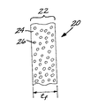
熱制御膜20はポリイミド材料から形成されたバインダ24とポリイミド材料全体にわたって分散されている充填材粒子26から形成されている自立型の薄いシート基板22を有する。充填材粒子26は各ドープされた金属酸化物粒子26の表面にオルガノシラン重合体のパッシベーション層を有する複数の白色のドープされた金属酸化物粒子である。ドープされた金属酸化物粒子26は熱制御膜20に導電性を与え、パッシベーション層28は粒子とポリイミド材料との間の化学反応の発生を減少させる。
【選択図】図1The thermal control film 20 has a self-supporting thin sheet substrate 22 formed from a binder 24 formed from a polyimide material and filler particles 26 dispersed throughout the polyimide material. Filler particles 26 are a plurality of white doped metal oxide particles having an organosilane polymer passivation layer on the surface of each doped metal oxide particle 26. The doped metal oxide particles 26 provide conductivity to the thermal control film 20 and the passivation layer 28 reduces the occurrence of chemical reactions between the particles and the polyimide material.
[Selection] Figure 1
Description
【技術分野】
【0001】
本発明は宇宙環境における物体の保護に関し、特に累積した電荷を放散させるのに十分に導電性の白色の熱制御膜に関する。
【背景技術】
【0002】
宇宙船はサービス中に広範囲の熱環境にさらされる。宇宙船の片側は自由空間に面し、他方の側は太陽に面する。宇宙船を冷却するために熱は自由空間に放射されるが、宇宙船は直接的な太陽光で集中的に加熱される。
【0003】
能動的および受動的な温度制御技術が人または感度の高い器機を含んでいる宇宙船の内部温度を許容可能な動作限度内に維持するために使用されている。能動的な温度制御は電気ヒータ、電気クーラ、ヒートパイプ等の機械または電気装置を通常含んでいる。本発明は受動的な温度制御を扱い、これは機械または電気装置を使用しない。
【0004】
受動的な温度制御に対する1つの方法は、時には“太陽遮蔽”または“熱ブランケット”と呼ばれる自立型の熱制御膜を使用する。熱制御膜は、太陽と保護される構造との間に位置され、太陽の直接光が構造と接触するのを阻止するためにややパラソルと同様の機能を行う。熱制御膜は最大の放射性と最小の太陽光吸収を実現するため白色であることが望ましく、それによって自立型の膜はサービス中に過度な高温に加熱されない。
【発明の開示】
【発明が解決しようとする課題】
【0005】
自立型の熱制御膜は同時に静電荷を所望に放散させるので望ましい。宇宙での構造は太陽風のフラックス中にあり、これは電子を静電荷として構造の表面に付着させる。静電荷が放散しなければこれは電気装置の動作に干渉するレベルまで強まり、構造を損傷するスパークの形態で放電を発生する。
【0006】
種々の技術が白色で、静電気を放散させる自立型の熱制御膜を製造するために使用されている。その1つでは導電性の層が無充填のポリイミド膜の表面に付着される。これらの熱制御膜は静電荷の放散と合理的に良好な放射性を与えるが、高価で脆弱であり、管理およびサービス中に容易に損傷を受ける。別の方法では、ポリイミドが導電性の炭素粒子で充満されており、これは黒色の導電基板を形成し、必要な熱特性を与えるために白色に塗装する。この方法により製造される熱制御膜は実施可能であるが、高価で重く、サービス中に基板から塗装の剥離が生じやすい欠点がある。
【0007】
白色で電荷放散性の自立型の熱制御膜に対して改良された方法が必要とされている。本発明はこの必要性を満足させ、さらに関連する利点を提供する。
【課題を解決するための手段】
【0008】
本発明は静電荷を放散させるために十分な導電性の自立型の白色の熱制御膜を提供する。白色および静電荷放散能力は、基板表面に設けられた異なる組成の被覆または層によってではなく基板膜中に埋設された充填材粒子によって得られる。結果的に被覆または層の接着剥離による故障の可能性はない。さらに、自立型の熱制御膜は通常の膜形成技術により生成される単一の層だけを有するので、重量が軽く比較的廉価である。
【0009】
本発明によれば、熱制御膜は重合体材料からなるバインダと、重合体材料全体に分散される複数の充填材粒子とから形成される自立型のシート基板を含んでいる。複数の充填材粒子はシート基板の重合体材料との化学反応を阻止するためにパッシベーションされている表面を有する複数の粒子で構成されている。
【0010】
好ましくは、充填材粒子は白色である。充填材粒子は粒子に対して制御された導電性レベルを与えるようにドープされている実質的に非導電性のセラミック材料で構成されることが望ましい。充填材粒子は金属酸化物粒子に所望レベルの導電性を与える物質でドープされている金属酸化物粒子が好ましく、亜鉛酸化物粒子が最も好ましい。オルガノシラン重合体のパッシベーション表面層は粒子上に存在することが好ましい。
【0011】
バインダは望ましくはポリイミドである。好ましいポリイミドは部分的に予め重合され弗素化された光学的に透明の芳香ポリイミドであり、それは最初に粉末形態で与えられ、その後充填材粒子を分散して自立型のシートに処理される。シート基板は典型的に約0.001インチ乃至約0.003インチの厚さを有する。
【0012】
熱制御膜により保護された構造は物体表面を有する物体と、物体表面の少なくとも一部分を保護するように位置付けられた自立型の熱制御膜とを具備している。熱制御膜は重合体材料のバインダと重合体材料中に全体的に分散されている複数の粒子とを有している。複数の充填材粒子はシート基板の重合体材料との化学反応を阻止するために表面がパッシベーションされている複数の粒子で構成されている。
【0013】
本発明者は好ましい金属酸化物粒子を、自立型の性質を与えるのに必要な機械特性を有する膜が得られるようにポリイミドのような重合体バインダ中へ含ませることが困難であることを観察した。金属酸化物充填材粒子は膜がその所望の物理的特性に物理的に形成される前に重合体の先駆物質の早期の重合化の触媒の作用をする可能性がある。本発明の方法では、粒子の充填材の表面は重合体の触媒化の傾向を減少するためにパッシベーションされる。さらに、好ましい重合体は早期の完全な重合化の触媒となる傾向が減少している部分的に予め重合化されたポリイミド樹脂である。その結果、粒子で充填された膜材料が準備され、重合化の前に所望の形状に物理的に形成される。これは、強度と物理的な一体性が劣り自立型の形態では通常使用されない従来の塗装処理とは対照的に、自立型の形状でその一体性を維持するのに十分な物理的強度を有する自立型のシートとして形成されることができる。
【0014】
この熱制御膜は必要な白色と、静電荷を除去するのに十分な導電性を有する単一の層であるので、通常の膜形成技術により製造されることは経済的であり、製造とサービスとの両面で非常に頑丈である。
【発明を実施するための最良の形態】
【0015】
本発明の他の特徴および利点は、本発明の原理を例示により示している添付図面を伴った好ましい実施形態の以下のさらに詳細な説明から明白になるであろう。しかしながら本発明の技術的範囲はこの好ましい実施形態に限定されるものではない。
図1は本発明にしたがった自立型の熱制御膜を示している。熱制御膜20は重合体材料から形成されたバインダ24を含む自立型のシート基板22を具備している。熱制御膜は動作可能な厚さで作られる自立型の素子であるが、好ましい厚さtf は約0.001から約0.003インチである(“自立型の”材料は例えば表面上に平らに支持される塗装層と対比され、塗装層は通常幾つかの点から支持されるとき完全な状態であるように十分な結合力をもたない)。複数の充填材粒子26(顔料の役目)は重合体材料全体に分散される。乾燥前には、重合体の溶剤も存在するが、溶剤は蒸発中に蒸発される。充填材粒子26、バインダ24、溶剤の組成、それらの割合、熱制御膜20の処理を次にさらに詳細に説明する。
【0016】
充填材粒子26は完成された熱制御膜20へ白色を与えるため白色であることが好ましい。充填材粒子は実質上非導電性のセラミック材料で構成され、それは充填材粒子と熱制御膜20に対して制御されたレベルの電気抵抗を与えるようにドープされている。熱制御膜20のバルク(容積)電気抵抗は好ましくは約1×10⁶ から約1×10⁹ オームセンチメートルである。抵抗がこの範囲外であるならば、熱制御膜20は熱制御には機能するが、電荷の放散において最も有効に機能するには抵抗が非常に大きいか非常に小さい。
【0017】
充填材粒子はドープされた金属酸化物組成物が好ましく、ドープされた亜鉛酸化物が最も好ましい。他のドープされた金属酸化物が使用されてもよく、またはそれに加えて簡単な酸化物の二酸化チタニウム(TiO2 )または酸化錫(SnO2 )または複素酸化物の亜鉛ガリウム酸化物(ZnGa2 O4 )または亜鉛アルミニウム酸化物(ZnAl2 O4 )またはその混合物等の亜鉛酸化物が使用されてもよい。
【0018】
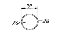
ドーパントは任意の動作可能な方法で製造される。例えば1方法では、亜鉛酸化物がアルミニウム、ガリウムまたはインジウムのような浅くドナー不純物で化学的にドープされてもよい。別の方法では亜鉛酸化物は天然の欠陥がドーパントを形成するように水素ガスでの加熱により還元されてもよい。水素ガス中での還元はZnOを形成し、ここで酸素の欠損はドナー状態であり、さらにZn+ Oを形成し、ここでは亜鉛の格子間原子はドナー状態である。適切なドープされた顔料粒子とそれらの処理については例えば米国特許第5,094,693 号、第5,820,669 号、第6,099,639 号明細書に記載されている。ドーパントは好ましくは総粒子重量の約0.1重量パーセント乃至約3.5重量パーセントの濃度で存在する。充填材粒子の形状および寸法は臨界的ではない。しかしながら充填材粒子は熱制御膜の厚さtf よりも非常に小さい直径dp を有することが望ましい。dp 値がtf 値に近付くと、充填材粒子は膜を破る可能性が生じる。tf が約0.001乃至約0.003インチの典型的な場合には、dp は好ましくは約0.1マイクロメートル乃至約5.0マイクロメートルであり、最も好ましくは効率的な光散乱が得られるように約0.3マイクロメートル乃至約0.7マイクロメートルの範囲である。
【0019】
図2で示されているように、充填材粒子26には薄いパッシベーション表面層28が配置されている(図2は実寸大ではないが、通常表面層28は非常に薄いため図面で実寸の大きさを示すことはできない)。パッシベーション表面層28はバインダの完全な重合化の前にバインダ24と充填材粒子26との触媒反応を防止し、それによってバインダ24の早期の重合化を防ぐように作用する。パッシベーション表面層28は非常に薄く、その厚さはそれを形成することに使用されるプロセスに基づいている。しかしながら典型的に、表面層28は約50乃至約100ナノメートル程度の厚さを有する基本的な疎水性単一層である。パッシベーション表面層28は好ましくはオルガノシラン重合体である。このようなオルガノシラン重合体の例および粒子を被覆する技術は米国特許第5,756,788 号、第5,565,591 号、第5,486,631 号明細書に記載されている。粒子を表面層28で被覆するための本発明で適用される別の技術はW.J van Ooiji の文献(“Protecting metals with silane coupling agents ”、Chemtech、1998年2月、26〜35頁)に記載されているものである。このような方法では、ビスー1,2−(トリエトキシ)エタンが水で加水分解され、その後充填材粒子は溶液に混合され、それによって疎水性表面層28が粒子上に形成される。
【0020】
バインダ24はポリイミドであることが好ましい。ポリイミドはUV放射に耐性であり、その結果、太陽エネルギを吸収する暗色化は膜にほとんど存在しない。好ましいポリイミドはSRS Technologies、Huntsville、ALから市場で入手可能なLaRC−CP1またはLaRC−CP2ポリイミドである。LaRC−CP1とLaRC−CP2重合体は米国特許第5,428,102 号明細書に記載されている。LaRC−CP1またはLaRC−CP2ポリイミドは予め重合化されていない形状よりも早期の重合化に対して感度が少ない部分的に予め重合化されている形状の先駆物質として仕上げられ使用される。即ち重合化プロセスは充填材粒子が導入されるときに開始されるがその時に重合は完了していない。重合化が完了した後、LaRC−CP1ポリイミドはクリアであり、黄ばんだ鋳造形態をもたず、宇宙環境での長期間にわたり透明度を維持する。これによって熱制御膜は長期間にわたって宇宙での露出中にバインダ24の変化から生じる黄ばみまたはその他の色の変色によって妨害されずに充填材粒子26の白色を保持することが可能である。
【0021】
好ましい実施例では、溶剤の蒸発後、充填材粒子26はバインダ24の約100乃至約300重量パーセントの濃度で存在し、最も好ましくは約150乃至約200重量パーセントの濃度で存在する。バインダ24は基板22の残りの容積を占めている。
【0022】
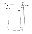
図3は物体表面44を有する物体42を備えた構造40を示している。熱制御膜20は物体表面44、したがって物体42を保護するために設置されている。物体42は典型的には宇宙船であり、特にアンテナ、バス構造ポートまたはその他の露出された機構のような宇宙船の一部である。図示の構造40では、隔離固定具46により物体42から隔てられて熱制御膜20を覆って位置して支持されている。これらの隔離固定具46は熱制御膜20から導電性の物体42へ、したがって接地へ静電荷を誘導するために導電性であり、また別個の導体が熱制御膜20から接地へ設けられてもよい。
【0023】
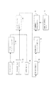
図4は熱制御膜20を準備し、物体42を保護するための好ましい方法のブロックフロー図である。充填材粒子26はブロック60で与えられ、ブロック62でパッシベーション表面層28を被覆される。本発明を実施するため、本発明者はQivaStar PO6ドープされた亜鉛酸化物粒子としてドープされた充填材粒子26を準備し、パッシベーション表面層28はSunsmart、Wainscott 社、NYにより供給される商用の被覆PS1256/4を使用する。米国特許第5,428,102 号明細書に記載された方法にしたがった予め重合化されたLaRC−CP1ポリイミド先駆物質がブロック64で与えられる。適切な溶剤はブロック66で与えられる。溶剤は望ましくは処理中に重合体の先駆物質の完全な溶解を達成する。LaRC−CP1ポリイミド先駆物質を使用する本発明の方法で実施可能な溶剤はメチルエチルケトン(MEK)、エチルアセテート、2−メトキシエチルエーテル(diglyme )、N,N−ジメチルアセトアミド(DMAC)を含んでいる。
【0024】
コンポーネントはブロック68で共に混合される。コンポーネントの好ましい比率は重量で約10部のLaRC−CP1ポリイミド先駆物質と、重量で約10乃至約20部のドープされて被覆された亜鉛酸化物粒子顔料と、重量で約60乃至約100部の溶剤である。ポリイミドは溶剤中に溶解され、被覆された充填材粒子は結果として生成された溶液中でスラリーにされる。溶剤はその後の処理中に蒸発される。この充填材粒子の量は最終的な熱制御膜20において約1:1乃至約2:1の最適な粒子対バインダ重量比をもたらす。粒子対バインダ重量比が約1:1よりも小さいならば、熱制御膜は動作は可能であるが、熱および電気特性は妥協される。粒子対バインダ重量比が約2:1よりも大きいならば、熱制御膜は動作は可能であるが、機械的特性が低下され、自立型の膜を形成するのに不十分である。
【0025】
混合の実施はセラミック蓋を有するセラミック粉砕ジャー中で行われる。コンポーネントは最小で8時間混合され、ヘグマン(Hegman)粉砕スケールで少なくとも7のヘグマングラインドを生成する。混合の完了後、混合物の粘度は時間の経過と共にゆっくりと増加することが観察される。混合物は約一週間使用可能であり、その後は、非常に粘性が高くなり鋳造できなくなる。
【0026】
動作可能な粘性の状態で、ブロック70において混合物は鋳造され、熱制御膜20のような膜を形成する。混合物は任意の実施可能な方法を使用して鋳造される。技術の実演では、混合物はプレートに鋳造され、膜の厚さに広げられることを可能にする。スピン鋳造が使用されてもよい。商用の実施では、他のタイプの薄い重合体膜の生成に広く使用されるような鋳造技術が使用されてもよい。
【0027】
薄膜はその後、ブロック72で溶剤を蒸発し重合体のバインダを硬化するために加熱される。好ましいLaRC−CP1ポリイミドバインダでは、加熱は260℃の温度で2時間、真空または空気循環炉で行われる。
【0028】
結果として生成された自立型の薄膜は白色である。これは必要な寸法に切断されてもよい。
【0029】
保護される物体は符号74で与えられる。自立型の熱制御膜20はブロック76で任意の動作可能な方法により物体42の表面44を保護するために設置される。例えば自立型の熱制御膜20は図3で示されているように隔離固定具46を使用して物体から離れて支持されてもよい。その代わりに、他の技術を使用して物体から支持されてもよい。また、代わりに、熱制御膜は他の構造から支持され、保護される物体表面を遮蔽するように位置されてもよい。
【0030】
本発明の特別な実施形態を説明のために詳細に説明したが、種々の変形および強化が本発明の技術的範囲を逸脱せずに行われてもよい。したがって、本発明の技術的範囲は特許請求の範囲の記載によってのみ限定される。
【図面の簡単な説明】
【0031】
【図1】本発明にしたがった自立型の熱制御膜の側面図。
【図2】熱制御膜で使用される粒子の拡大正面図。
【図3】図1の熱制御膜が物体を保護するために配置されている構造の側面図。
【図4】図1の熱制御膜と図3の構造の処理の方法のブロック図。【Technical field】
[0001]
The present invention relates to the protection of objects in the space environment, and more particularly to a white thermal control film that is sufficiently conductive to dissipate accumulated charge.
[Background]
[0002]
Spacecraft are exposed to a wide range of thermal environments during service. One side of the spaceship faces free space and the other side faces the sun. Heat is radiated into free space to cool the spacecraft, but the spacecraft is intensively heated by direct sunlight.
[0003]
Active and passive temperature control techniques are used to maintain the internal temperature of spacecraft, including humans or sensitive equipment, within acceptable operating limits. Active temperature control typically includes mechanical or electrical devices such as electric heaters, electric coolers, heat pipes and the like. The present invention deals with passive temperature control, which does not use mechanical or electrical equipment.
[0004]
One method for passive temperature control uses a free-standing thermal control film, sometimes referred to as a “sun shield” or “thermal blanket”. The thermal control film is located between the sun and the structure to be protected and performs a function somewhat like a parasol to prevent direct sunlight from coming into contact with the structure. The thermal control film is preferably white to achieve maximum emissivity and minimum solar absorption, so that the free-standing film is not heated to excessively high temperatures during service.
DISCLOSURE OF THE INVENTION
[Problems to be solved by the invention]
[0005]
A self-supporting thermal control film is desirable because it simultaneously dissipates electrostatic charges as desired. The structure in space is in the solar wind flux, which attaches electrons to the surface of the structure as electrostatic charges. If the static charge does not dissipate, it will build up to a level that interferes with the operation of the electrical device, generating a discharge in the form of a spark that damages the structure.
[0006]
Various techniques have been used to produce self-supporting thermal control films that are white and dissipate static electricity. In one, a conductive layer is deposited on the surface of an unfilled polyimide film. These thermal control films provide static charge dissipation and reasonably good radiation, but are expensive and fragile and are easily damaged during management and service. In another method, the polyimide is filled with conductive carbon particles, which forms a black conductive substrate and is painted white to provide the necessary thermal properties. Although the thermal control film produced by this method can be implemented, it is expensive and heavy, and has a drawback that the coating is easily peeled off from the substrate during service.
[0007]
There is a need for improved methods for white, charge-dissipating free-standing thermal control films. The present invention satisfies this need and provides further related advantages.
[Means for Solving the Problems]
[0008]
The present invention provides a self-supporting white thermal control film that is sufficiently conductive to dissipate electrostatic charges. White and electrostatic charge dissipation capabilities are obtained by filler particles embedded in the substrate film rather than by coatings or layers of different composition provided on the substrate surface. As a result, there is no possibility of failure due to debonding of the coating or layer. Furthermore, the self-supporting thermal control film has only a single layer produced by conventional film forming techniques, and thus is light and relatively inexpensive.
[0009]
According to the present invention, the thermal control film includes a self-supporting sheet substrate formed of a binder made of a polymer material and a plurality of filler particles dispersed throughout the polymer material. The plurality of filler particles are composed of a plurality of particles having a surface that is passivated to prevent chemical reaction with the polymeric material of the sheet substrate.
[0010]
Preferably, the filler particles are white. The filler particles are preferably composed of a substantially non-conductive ceramic material that is doped to provide a controlled conductivity level for the particles. The filler particles are preferably metal oxide particles doped with a material that imparts a desired level of conductivity to the metal oxide particles, and most preferably zinc oxide particles. The passivation surface layer of the organosilane polymer is preferably present on the particles.
[0011]
The binder is preferably polyimide. A preferred polyimide is a partially pre-polymerized and fluorinated optically clear aromatic polyimide, which is first provided in powder form and then processed into a free-standing sheet by dispersing the filler particles. The sheet substrate typically has a thickness of about 0.001 inches to about 0.003 inches.
[0012]
The structure protected by the thermal control film comprises an object having an object surface and a freestanding thermal control film positioned to protect at least a portion of the object surface. The thermal control film has a binder of polymer material and a plurality of particles dispersed throughout the polymer material. The plurality of filler particles are composed of a plurality of particles whose surfaces are passivated to prevent chemical reaction with the polymer material of the sheet substrate.
[0013]
The inventor has observed that it is difficult to include the preferred metal oxide particles in a polymer binder such as polyimide so as to obtain a film having the mechanical properties necessary to provide self-supporting properties. did. The metal oxide filler particles may act as a catalyst for premature polymerization of the polymer precursor before the film is physically formed to its desired physical properties. In the process of the present invention, the surface of the particle filler is passivated to reduce the tendency of the polymer to catalyze. In addition, preferred polymers are partially prepolymerized polyimide resins that have a reduced tendency to become early complete polymerization catalysts. As a result, a membrane material filled with particles is prepared and physically formed into the desired shape prior to polymerization. It has sufficient physical strength to maintain its integrity in a self-supporting shape, as opposed to a traditional coating process that is poor in strength and physical integrity and is not normally used in a self-supporting form It can be formed as a self-supporting sheet.
[0014]
Since this thermal control film is a single layer with the necessary white color and sufficient conductivity to remove the static charge, it is economical to manufacture by normal film forming technology, manufacturing and service And very sturdy on both sides.
BEST MODE FOR CARRYING OUT THE INVENTION
[0015]
Other features and advantages of the present invention will become apparent from the following more detailed description of the preferred embodiment, taken in conjunction with the accompanying drawings, illustrating by way of example the principles of the invention. However, the technical scope of the present invention is not limited to this preferred embodiment.
FIG. 1 shows a self-supporting thermal control film according to the present invention. The
[0016]
The
[0017]
The filler particles are preferably doped metal oxide compositions, most preferably doped zinc oxide. Other doped metal oxides may be used, or in addition to simple oxides titanium dioxide (TiO 2 ) or tin oxide (SnO 2 ) or complex oxides zinc gallium oxide (ZnGa 2 O 4 ) or zinc oxides such as zinc aluminum oxide (ZnAl 2 O 4 ) or mixtures thereof may be used.
[0018]
The dopant is produced by any operable method. For example, in one method, zinc oxide may be chemically doped with a shallow donor impurity such as aluminum, gallium or indium. Alternatively, the zinc oxide may be reduced by heating with hydrogen gas so that natural defects form a dopant. Reduction in hydrogen gas forms ZnO, where oxygen vacancies are in a donor state, further forming Zn + O, where the zinc interstitial atoms are in the donor state. Suitable doped pigment particles and their processing are described, for example, in US Pat. Nos. 5,094,693, 5,820,669, and 6,099,639. The dopant is preferably present at a concentration of about 0.1 weight percent to about 3.5 weight percent of the total particle weight. The shape and size of the filler particles is not critical. However, it is desirable that the filler particles have a diameter d p that is much smaller than the thickness t f of the thermal control film. If d p value approaches t f value, filler particles possibly break the membrane occurs. In the typical case where t f is about 0.001 to about 0.003 inches, d p is preferably about 0.1 micrometers to about 5.0 micrometers, most preferably efficient light scattering. In the range of about 0.3 micrometers to about 0.7 micrometers.
[0019]
As shown in FIG. 2, the
[0020]
The
[0021]
In the preferred embodiment, after solvent evaporation,
[0022]
FIG. 3 shows a structure 40 with an
[0023]
FIG. 4 is a block flow diagram of a preferred method for preparing the
[0024]
The components are mixed together at
[0025]
The mixing is performed in a ceramic grinding jar having a ceramic lid. The components are mixed for a minimum of 8 hours to produce at least 7 Hegman grinds on a Hegman grinding scale. After mixing is complete, it is observed that the viscosity of the mixture increases slowly over time. The mixture can be used for about a week, after which it becomes very viscous and cannot be cast.
[0026]
In an operable viscosity state, the mixture is cast at
[0027]
The film is then heated at block 72 to evaporate the solvent and cure the polymeric binder. In a preferred LaRC-CP1 polyimide binder, the heating is performed in a vacuum or air circulating furnace at a temperature of 260 ° C. for 2 hours.
[0028]
The resulting free-standing film is white. This may be cut to the required dimensions.
[0029]
The object to be protected is given 74. A free-standing
[0030]
While specific embodiments of the invention have been described in detail for purposes of illustration, various modifications and enhancements may be made without departing from the scope of the invention. Therefore, the technical scope of the present invention is limited only by the description of the scope of claims.
[Brief description of the drawings]
[0031]
FIG. 1 is a side view of a self-supporting thermal control film according to the present invention.
FIG. 2 is an enlarged front view of particles used in a thermal control film.
FIG. 3 is a side view of a structure in which the thermal control film of FIG. 1 is arranged to protect an object.
4 is a block diagram of a method of processing the thermal control film of FIG. 1 and the structure of FIG.
Claims (13)
重合体材料全体に分散され、シート基板(22)の重合体材料との化学反応を阻止するためにパッシベーションされている表面を有する複数の粒子で構成されている充填材粒子(26)とを含んでいる熱制御膜(20)。A free-standing sheet substrate (22) comprising a binder (24) formed from a polymeric material;
Filler particles (26) comprised of a plurality of particles dispersed throughout the polymer material and having a surface that is passivated to prevent chemical reaction with the polymer material of the sheet substrate (22). Thermal control membrane (20)
物体表面(44)を有する物体(42)と、
物体表面(44)の少なくとも一部を保護するために設置された自立型の熱制御膜(20)とを具備し、この熱制御膜(20)は、
重合体材料から形成されたバインダ(24)を含む自立型のシート基板(22)と、
重合体材料全体に分散され、シート基板(22)の重合体材料との化学反応を阻止するためにパッシベーションされている表面を有する複数の粒子で構成されている充填材粒子(26)とを具備している構造。In the structure protected by the thermal control film (20),
An object (42) having an object surface (44);
A self-supporting thermal control film (20) installed to protect at least part of the object surface (44), the thermal control film (20),
A free-standing sheet substrate (22) comprising a binder (24) formed from a polymer material;
Filler particles (26) composed of a plurality of particles dispersed throughout the polymer material and having a surface that is passivated to prevent chemical reaction with the polymer material of the sheet substrate (22). Structure.
Applications Claiming Priority (2)
| Application Number | Priority Date | Filing Date | Title |
|---|---|---|---|
| US85523201A | 2001-05-14 | 2001-05-14 | |
| PCT/US2002/011800 WO2002097829A1 (en) | 2001-05-14 | 2002-04-11 | Charge-dissipating, white thermal control film, and structures utilizing the thermal control film |
Publications (2)
| Publication Number | Publication Date |
|---|---|
| JP2005508564A true JP2005508564A (en) | 2005-03-31 |
| JP4420323B2 JP4420323B2 (en) | 2010-02-24 |
Family
ID=25320690
Family Applications (1)
| Application Number | Title | Priority Date | Filing Date |
|---|---|---|---|
| JP2003500926A Expired - Fee Related JP4420323B2 (en) | 2001-05-14 | 2002-04-11 | Charge dissipating white thermal control film and structure using the thermal control film |
Country Status (3)
| Country | Link |
|---|---|
| EP (1) | EP1405317B1 (en) |
| JP (1) | JP4420323B2 (en) |
| WO (1) | WO2002097829A1 (en) |
Cited By (1)
| Publication number | Priority date | Publication date | Assignee | Title |
|---|---|---|---|---|
| JP2013541181A (en) * | 2010-08-18 | 2013-11-07 | イー・アイ・デュポン・ドウ・ヌムール・アンド・カンパニー | Light emitting diode assembly and thermal control blanket and method related thereto |
Families Citing this family (2)
| Publication number | Priority date | Publication date | Assignee | Title |
|---|---|---|---|---|
| US8853723B2 (en) | 2010-08-18 | 2014-10-07 | E. I. Du Pont De Nemours And Company | Light emitting diode assembly and thermal control blanket and methods relating thereto |
| WO2015029975A1 (en) * | 2013-08-28 | 2015-03-05 | 三菱重工業株式会社 | Flexible thermal-control material, and production method therefor |
Family Cites Families (3)
| Publication number | Priority date | Publication date | Assignee | Title |
|---|---|---|---|---|
| US5215824A (en) * | 1990-12-05 | 1993-06-01 | General Electric Co. | RF-transparent spacecraft thermal control barrier |
| US5490893A (en) * | 1992-05-22 | 1996-02-13 | Avery Dennison Corporation | Thermoformable conductive laminate and process |
| US5798060A (en) * | 1997-02-06 | 1998-08-25 | E. I. Du Pont De Nemours And Company | Static-dissipative polymeric composition |
-
2002
- 2002-04-11 EP EP02774098A patent/EP1405317B1/en not_active Expired - Lifetime
- 2002-04-11 WO PCT/US2002/011800 patent/WO2002097829A1/en not_active Ceased
- 2002-04-11 JP JP2003500926A patent/JP4420323B2/en not_active Expired - Fee Related
Cited By (1)
| Publication number | Priority date | Publication date | Assignee | Title |
|---|---|---|---|---|
| JP2013541181A (en) * | 2010-08-18 | 2013-11-07 | イー・アイ・デュポン・ドウ・ヌムール・アンド・カンパニー | Light emitting diode assembly and thermal control blanket and method related thereto |
Also Published As
| Publication number | Publication date |
|---|---|
| WO2002097829A8 (en) | 2003-02-27 |
| JP4420323B2 (en) | 2010-02-24 |
| WO2002097829A1 (en) | 2002-12-05 |
| EP1405317B1 (en) | 2011-08-24 |
| EP1405317A1 (en) | 2004-04-07 |
Similar Documents
| Publication | Publication Date | Title |
|---|---|---|
| EP3167013B1 (en) | Thermal control coatings | |
| JP4963788B2 (en) | Sol-gel coating for solar cells | |
| US8029702B2 (en) | Low solar absorptance, high emissivity, inorganic electrostatic dissipative thermal control coating | |
| JP5228376B2 (en) | Infrared shielding fine particles and manufacturing method thereof, infrared shielding fine particle dispersion, infrared shielding body, and infrared shielding base material | |
| EP0383909B1 (en) | Method for protection of spacecraft against electrostatic discharge | |
| US5807909A (en) | (Zinc, cadmium) aluminate-gallate-containing organic-binder paint and film articles | |
| EP0681911B1 (en) | Coated article | |
| US6176453B1 (en) | Radiator using thermal control coating | |
| Zheng et al. | Al2O3/graphene/PVDF‐HFP radiative cooling coating reinforced heat dissipation of BIPV modules | |
| JP4420323B2 (en) | Charge dissipating white thermal control film and structure using the thermal control film | |
| TWI302151B (en) | Moisture barrier resins | |
| US6576290B2 (en) | Method of preparation of an electrically conductive paint | |
| US8038910B2 (en) | Low solar absorptance, high emissivity, inorganic electrostatic dissipative thermal control coating | |
| CN117343608A (en) | An infrared stealth coating material and its preparation method | |
| CN116426144A (en) | Radiation-resistant thermal control filler and antistatic thermal control coating and preparation method thereof | |
| JP5910095B2 (en) | Weather-resistant composition, weather-resistant film and weather-resistant substrate using the same | |
| KR102199935B1 (en) | Peelable solar heat barrier coating solution composition | |
| US7014915B2 (en) | Controlled binary macrosegregated powder particles, their uses, and preparation methods therefor | |
| JP2015160390A (en) | Heat ray shielding laminate and heat ray shielding structure | |
| CN115806752B (en) | Antistatic electric control coating and preparation method thereof | |
| CN100385258C (en) | Anti-radiation conductive optical protective film |
Legal Events
| Date | Code | Title | Description |
|---|---|---|---|
| A621 | Written request for application examination |
Free format text: JAPANESE INTERMEDIATE CODE: A621 Effective date: 20050324 |
|
| A977 | Report on retrieval |
Free format text: JAPANESE INTERMEDIATE CODE: A971007 Effective date: 20071010 |
|
| A131 | Notification of reasons for refusal |
Free format text: JAPANESE INTERMEDIATE CODE: A131 Effective date: 20071016 |
|
| A601 | Written request for extension of time |
Free format text: JAPANESE INTERMEDIATE CODE: A601 Effective date: 20080109 |
|
| A602 | Written permission of extension of time |
Free format text: JAPANESE INTERMEDIATE CODE: A602 Effective date: 20080117 |
|
| A601 | Written request for extension of time |
Free format text: JAPANESE INTERMEDIATE CODE: A601 Effective date: 20080218 |
|
| A602 | Written permission of extension of time |
Free format text: JAPANESE INTERMEDIATE CODE: A602 Effective date: 20080225 |
|
| A521 | Request for written amendment filed |
Free format text: JAPANESE INTERMEDIATE CODE: A523 Effective date: 20080317 |
|
| A131 | Notification of reasons for refusal |
Free format text: JAPANESE INTERMEDIATE CODE: A131 Effective date: 20080617 |
|
| A601 | Written request for extension of time |
Free format text: JAPANESE INTERMEDIATE CODE: A601 Effective date: 20080917 |
|
| A602 | Written permission of extension of time |
Free format text: JAPANESE INTERMEDIATE CODE: A602 Effective date: 20080925 |
|
| A521 | Request for written amendment filed |
Free format text: JAPANESE INTERMEDIATE CODE: A523 Effective date: 20081217 |
|
| TRDD | Decision of grant or rejection written | ||
| A01 | Written decision to grant a patent or to grant a registration (utility model) |
Free format text: JAPANESE INTERMEDIATE CODE: A01 Effective date: 20091027 |
|
| A01 | Written decision to grant a patent or to grant a registration (utility model) |
Free format text: JAPANESE INTERMEDIATE CODE: A01 |
|
| RD03 | Notification of appointment of power of attorney |
Free format text: JAPANESE INTERMEDIATE CODE: A7423 Effective date: 20091109 |
|
| A61 | First payment of annual fees (during grant procedure) |
Free format text: JAPANESE INTERMEDIATE CODE: A61 Effective date: 20091126 |
|
| FPAY | Renewal fee payment (event date is renewal date of database) |
Free format text: PAYMENT UNTIL: 20121211 Year of fee payment: 3 |
|
| R150 | Certificate of patent or registration of utility model |
Ref document number: 4420323 Country of ref document: JP Free format text: JAPANESE INTERMEDIATE CODE: R150 Free format text: JAPANESE INTERMEDIATE CODE: R150 |
|
| FPAY | Renewal fee payment (event date is renewal date of database) |
Free format text: PAYMENT UNTIL: 20121211 Year of fee payment: 3 |
|
| RD04 | Notification of resignation of power of attorney |
Free format text: JAPANESE INTERMEDIATE CODE: R3D04 |
|
| FPAY | Renewal fee payment (event date is renewal date of database) |
Free format text: PAYMENT UNTIL: 20131211 Year of fee payment: 4 |
|
| R250 | Receipt of annual fees |
Free format text: JAPANESE INTERMEDIATE CODE: R250 |
|
| R250 | Receipt of annual fees |
Free format text: JAPANESE INTERMEDIATE CODE: R250 |
|
| R250 | Receipt of annual fees |
Free format text: JAPANESE INTERMEDIATE CODE: R250 |
|
| R250 | Receipt of annual fees |
Free format text: JAPANESE INTERMEDIATE CODE: R250 |
|
| R250 | Receipt of annual fees |
Free format text: JAPANESE INTERMEDIATE CODE: R250 |
|
| R250 | Receipt of annual fees |
Free format text: JAPANESE INTERMEDIATE CODE: R250 |
|
| LAPS | Cancellation because of no payment of annual fees |