JP2005507837A - Sheet folding device - Google Patents
Sheet folding device Download PDFInfo
- Publication number
- JP2005507837A JP2005507837A JP2003534296A JP2003534296A JP2005507837A JP 2005507837 A JP2005507837 A JP 2005507837A JP 2003534296 A JP2003534296 A JP 2003534296A JP 2003534296 A JP2003534296 A JP 2003534296A JP 2005507837 A JP2005507837 A JP 2005507837A
- Authority
- JP
- Japan
- Prior art keywords
- folding
- sheet material
- blade
- bending
- rollers
- Prior art date
- Legal status (The legal status is an assumption and is not a legal conclusion. Google has not performed a legal analysis and makes no representation as to the accuracy of the status listed.)
- Pending
Links
Images


Classifications
-
- B—PERFORMING OPERATIONS; TRANSPORTING
- B65—CONVEYING; PACKING; STORING; HANDLING THIN OR FILAMENTARY MATERIAL
- B65H—HANDLING THIN OR FILAMENTARY MATERIAL, e.g. SHEETS, WEBS, CABLES
- B65H45/00—Folding thin material
- B65H45/12—Folding articles or webs with application of pressure to define or form crease lines
- B65H45/18—Oscillating or reciprocating blade folders
-
- B—PERFORMING OPERATIONS; TRANSPORTING
- B65—CONVEYING; PACKING; STORING; HANDLING THIN OR FILAMENTARY MATERIAL
- B65H—HANDLING THIN OR FILAMENTARY MATERIAL, e.g. SHEETS, WEBS, CABLES
- B65H2404/00—Parts for transporting or guiding the handled material
- B65H2404/10—Rollers
- B65H2404/14—Roller pairs
Abstract
シート材(248)の折り曲げ装置であって、折り曲げブレード(104)と、2つの折り曲げローラ(106)と、折り曲げブレード(104)を押し付けるピンチ足部(120)と、折り曲げブレード(104)及び折り曲げローラ(106)の少なくとも一方を互いに作動連通する状態に移動させる駆動手段(180)などを備えており、折り曲げローラ(106)の各々が、折り曲げブレード(104)の長手軸に平行な軸を中心にして回転するシート材折り曲げ装置。A folding device for a sheet material (248), comprising a folding blade (104), two folding rollers (106), a pinch foot (120) for pressing the folding blade (104), a folding blade (104) and a folding Drive means (180) for moving at least one of the rollers (106) into a state of being in operative communication with each other, and each of the folding rollers (106) is centered on an axis parallel to the longitudinal axis of the folding blade (104) A sheet material bending device that rotates in a straight line.
Description
【技術分野】
【0001】
本発明は、包括的にはシート材の折り曲げに、特に折り曲げブレードに対して長手方向に配置された折り曲げローラを用いたシート折り曲げ装置に関する。
【背景技術】
【0002】
印刷済みシートを仕上げて冊子にするシステムが、PCT第WO00/18583号(以下TrovingerのPCTとする)に記載されており、その全体を参照により本明細書で援用する。TrovingerのPCTは、2つの駆動モータアセンブリを用いて個々の冊子シートを折り曲げる動作を含む。第1垂直駆動モータアセンブリが、折り曲げアセンブリでシートを折り曲げブレードに押し付けることによってシートを固定するように機能する。この第1垂直駆動モータアセンブリは、1組の折り曲げローラをシート及び長手方向折り曲げブレードの両方と接触する位置へ移動させる。折り曲げローラの回転軸は、各シートを折り曲げるために使用される折り曲げブレードに対して垂直である。次に、第2水平駆動モータが、シートと接触状態に置かれている折り曲げローラ組を折り曲げブレードに沿って前後に往復移動させることによって、シートを折り曲げブレードに当てて変形させるように働き、これにより、実際にシートに折り目が付けられる。これらの折り曲げローラの数及び間隔は、折り曲げローラの水平移動中に、少なくとも1つの折り曲げローラが、折り目を付けようとするシート部分に沿ったすべての点を通過するように定められる。
【0003】
TrovingerのPCTに記載されているシステムは、折り曲げローラを2軸方向に直線移動させて折り目を付けるために、2つの個別モータを使用している。折り目を付けるために必要な時間は、折り曲げアセンブリを垂直方向に移動させる時間、及びシートに折り目を付けるために折り曲げローラを水平方向に移動させる時間の合計である。
【0004】
別の折り曲げ装置が、米国特許第4,053,150号(Lane)に開示されており、これは、その全体が参照によって本明細書に援用され、隅部の折れの防止を対象としている。Lane特許は、一度折り曲げた紙(たとえば、折り曲げ済みの新聞印刷紙)を1対のローラ間に押し進め、それによって紙を四つ折りにするためのブレードを備えている。Lane特許では、紙の縁部及び隅部の折れを防止するために、空気流ジェット及びプレートを使用している。しかし、Lane特許は、正確ではっきりした折り目を付けることや、折り曲げ工程中に確実に紙を適正に整列させることができない。
【0005】
装置コスト、及びシートに正確な折り目を付けるために必要な時間を減少させることが、望ましいであろう。
【発明の開示】
【0006】
本発明は、単一のモータと、折り曲げブレードに対して長手方向に配置された折り曲げローラとを使用して、シート材を折り曲げる装置を対象としている。
【0007】
本発明の例示的な実施形態によれば、シート材折り曲げ装置であって、折り曲げブレードと、2つの折り曲げローラと、折り曲げブレードを押し付けるピンチ足部と、折り曲げブレード及び折り曲げローラの少なくとも一方を互いに作動連通する状態に移動させる駆動手段などを備えており、折り曲げローラの各々が、折り曲げブレードの長手軸に平行な軸を中心にして回転するシート材折り曲げ装置が提供される。
【0008】
本発明の第2の実施形態によれば、シート材を折り曲げる方法であって、シート材を2つの折り曲げローラ及び折り曲げブレード間の領域に送り込むステップと、シート材をピンチ足部で折り曲げブレードに押し付けるステップと、折り曲げローラ及び折り曲げブレードを相対的に移動させるステップであって、それにより、折り曲げブレードを使用してシート材に折り目を付ける、移動させるステップとを含み、各折り曲げローラは、折り曲げブレードの長手軸に平行な軸を中心にして回転するシート材を折り曲げる方法が提供される。
【0009】
本発明の他の目的及び利点は、同様な部材を同様な参照番号で表している添付図面と組み合わせて読めば、好適な実施形態の以下の詳細な説明からさらに明らかになるであろう。
【発明を実施するための最良の形態】
【0010】
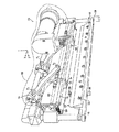
シート材を折り曲げる装置が、図1A及び図1Bに装置100として示されている。例示的な装置100は、図1Aのx軸に沿った長手軸を有する折り曲げブレード、たとえば、折り曲げブレード104を有する。折り曲げブレード104は、ブレードホルダ134によって保持されているように図示されているが、別法として任意の他の安定化構造によって保持することができ、あるいは、ブレードホルダ134と一体部材として製造することもできる。折り曲げブレード104は、ブレードモータ136のような装置を用いて固定することができるが、別法として(たとえば、図1Aのy軸に沿って、または任意の所望軸の方向に)移動可能にしてもよい。たとえば、ブレードモータ136は、歯車または任意の他の手段を使用して、ブレードホルダ134に取り付けられている(図1Bに示された)スライドアーム140によって折り曲げブレード104及びブレードホルダ134を、長手方向がy軸方向に位置するレール128に沿って並進させることができる。そのような移動を使用して、折り曲げブレード104を越えるシート材の送り込みを容易にすることができる。
【0011】
折り曲げブレード104は、金属または任意の他の成形可能な材料で形成することができ、(図1A、図1B、図2A〜図2C、図4A及び図4Bに示されているように)平坦なストリップとして成形できるが、(図3A〜図3Cに示されている)丸形にすることもでき、もちろん、これらの例は非制限的である。たとえば、別法として、折り曲げブレード104の断面(すなわち、y軸及びz軸を含む平面)が三角形でもよく、あるいは、(図2A及び図2Bに示された)ブレード面242a及び242bが、図示のように平坦ではなく、凹状または凸状であることもできる。
【0012】
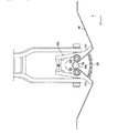
装置100はまた、2つの折り曲げローラ、たとえば、折り曲げローラ106を有し、これらは、図2Aでは2つの折り曲げローラ206として示されているが、別法として任意数にすることができる。図2A〜図2Cに示されているように、折り曲げブレード204は、2つの折り曲げローラ206間を通る平面上に位置している。図2Aには、この平面が点線244で示されている。例示の各折り曲げローラ106は、折り曲げブレードの長手軸に平行な軸を中心にして回転する。図1Aの例では、この回転軸がx軸方向である。折り曲げローラ106は、金属または任意の他の成形可能な材料で形成することができ、エラストマーなどの弾性または変形可能な材料で被覆することができる。また、折り曲げローラ106は、(図示のように)断面を円形にすることができるが、別法として、シート材に折り目を付けるために折り曲げブレード104と協働することができる任意の他の断面形状を有することができる。
【0013】
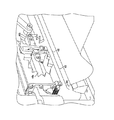
例示の各折り曲げローラ106は、図4A及び図4Bの直列配置形サブローラ446a〜446cなどの多数のサブローラを有し、サブローラ及びサブローラ間の間隔の合計長さが、少なくとも所望の折り目の長さである。たとえば、図4Aの例では、この合計長さが距離d1として表されており、サブローラ446a〜446cとその間の間隔の合計長さを含む。距離d1は、折り曲げブレード404の長手軸に沿ったシート材448の長さを表す紙長さl1と少なくとも同じ長さである。
【0014】
少なくとも折り曲げブレード及び複数の折り曲げローラを互いに作動連通(operable communication)する状態に移動させる、図1及び図2の駆動手段180のような駆動手段が設けられている。本明細書において「作動連通」とは、シート材に所望の折り目を付けることができるように、折り曲げブレード及び/または折り曲げローラを相対配置することを意味する。例示的な実施形態では、駆動手段180はカップリング116のようなカップリング及びカップリングに取り付けられた送りねじ110のようなアクチュエータを含み、ここで、送りねじが第1方向に回転することによって、折り曲げローラを移動させて折り曲げブレードに当接させ、それによってシート材に折り目を付けることができる。図1A及び図1Bに示された実施形態では、駆動手段180はカップリング116、送りねじ110、モータ114及び駆動ベルト132を含む。モータ114は、任意の従来形式(たとえば、電動式、空気圧式、または油圧式)にすることができるが、任意の他の形式にすることもできる。例示的な送りねじ110は、モータ114によって駆動ベルト132を介して、あるいは、チェーンなどの任意の他の動力伝達部材を介して回転させることができ、または、ピストンのような別のタイプのアクチュエータで置き替えられることもできる。
【0015】
装置100は、折り曲げローラを回転可能に取り付けたハウジング、たとえば、ハウジング102も有しており、ハウジングは、カップリングに取り付けられている。図1Bの例では、折り曲げローラ106は、ハウジング102の内側部分に取り付けられており、カップリング116は、ハウジング102の外側部分に取り付けられている。ハウジング102は、x軸方向に長手軸を有し、任意の成形可能な材料で、たとえば、制限的ではないが、金属またはプラスチックで形成することができる。
【0016】
例示的なカップリング116は、移動部材112を有しており、これは、内ねじの形成された部分を介して送りねじ110と噛み合い、当該技術分野では既知のように、送りねじ110の回転時にそれに沿って移動する。カップリング116はまた、リンク部材108も有し、これらは、任意の従来型または他のピボット手段によって、移動部材112及びハウジング102にそれぞれ(図1Bに示された)ピボット点P1及びP2で取り付けられている。別法として、カップリング116は、チェーンまたはベルトなどの任意の他の形式のカップリング部材を有することができる。
【0017】
本発明の例示的な図1Aの実施形態では、駆動手段180が、折り曲げようとするシート材に直交する直線経路に沿って折り曲げローラを移動させる。たとえば、送りねじ110の回転により、複数の移動部材112が送りねじ110に沿って移動する時、複数のリンク部材108がピボット点P1及びP2を中心にして回転する。ハウジング102は、複数のスライドアーム152及び複数のレール128によって、図1Aのx軸に沿う向きには拘束されており、複数のリンク部材108の回転により、ハウジング102が直線経路に沿って折り曲げブレード104に対して接離する方向に移動する。送りねじ110及びカップリング116を組み合わせて使用することにより、y方向に(すなわち、折り曲げブレード104に向かって)非常に大きい力を生じることができ、非制限的な例であるが、たとえば、従来型印刷用紙から肉厚紙料までの範囲にわたるシート材を有効に折り曲げることができる。別法として、送りねじ110及びカップリング116によって達成される単一運動を、他の機械的組み合わせ、たとえば、非制限的な例であるが、カム、ベルト/プーリ、及び歯車を含むシステムによって実施することができる。
【0018】
ハウジング102は、折り曲げブレードを押し付けるためのピンチ足部、たとえば、複数のピンチ足部120のうちの1つを含み、ピンチ足部は、ハウジングに弾性的に取り付けられている。各ピンチ足部120は、ピンチ溝154を有する。図1Bの例は、2つのピンチ足部120を示しているが、別法として、この数を増減させることができる。
【0019】
図2Aに示されているように、例示的な各ピンチ足部220は、ピンチばね222でハウジングに取り付けることができるが、別法として、任意の他の弾性取り付け手段を使用することができる。ピンチ足部220は、任意の成形可能な材料(金属及びプラスチックが非制限的な例である)か、または変形可能または弾性材料で形成することができる。ピンチ足部220は、シート材248を位置決めして折り曲げブレード204に対して当接保持するためのピンチ溝254を有し、ピンチ溝254は、逆V字形断面形状を有するように図示されているが、別法として、任意の他の断面形状(たとえば、半球形)にすることができる。
【0020】
図4Bのハウジング402の破断図に示されているように、ピンチ足部420は、2つのサブローラ446a及び446b間の隙間に配置されている。サブローラ446a〜446c間の隙間は、x軸に沿った長さを約8または9mmにすることができるが、増減させることもできる。
【0021】
ハウジング102は、シート材を折り曲げブレードの周囲に押し付けるための折り曲げフラップ、たとえば、2つの折り曲げフラップ118も備えている。図2に示されているように、折り曲げフラップ218(折り曲げフラップ118に対応)は、折り曲げ動作中にブレードホルダ234が折り曲げフラップ218間にはまるように、その間が任意角度θになるように配置することができる。折り曲げフラップ118は、ハウジング102と一体部材として、あるいはハウジング102とは別体にして製造することができ、また、ハウジング102と同一材料で、あるいは異なった成形可能な材料で製造することができる。折り曲げフラップ118は、ピボット点P3(図2A〜図2C及び図3A〜図3C)で互いに回動するように取り付けることができ、また、たとえば、フラップばね124を使用して、互いに近づく方向に回動可能に付勢することもできる。この構造によって、さまざまなシート材の厚さに対応するように、角度θを調節することができる。別法として、折り曲げフラップ118を互いに近づく方向に付勢するために、任意の他の弾性連結手段を使用することができるが、折り曲げフラップ118を互いに固定的に取り付けることもできる。
【0022】
図2A〜図2Cは、シート材を折り曲げる方法を例示的に示している。図4A及び図4Bは、同じ例示的な実施形態の、それぞれ斜視図及び破断図である。本方法は、シート材を少なくとも1つのローラ及び折り曲げブレード間の領域に送り込むステップを含む。このステップは、たとえば、図2Aに示されており、シート材248が、たとえば、トリム装置などの上流側アセンブリによって、折り曲げローラ206及び折り曲げブレード204間に送られる。もちろん、シート材248は、+z軸または−z軸方向に送ることができる。このステップは、シート材448を送り込み中の図4Aの例にも示されている。
【0023】
シート材をピンチ足部で折り曲げブレードに押し付けるステップが、例示的方法に含まれる。たとえば、ピンチ足部220は、最初にシート材248に係合し、シート材248の、折り目を付けようとする部分をピンチ溝254で折り曲げブレード204に押し付け、これにより、シート材248を折り曲げブレード204に固定する。このようにして、ピンチ足部220は、折り曲げブレード204に対するシート材の適切な位置決めを確保することによって、折り目位置を定める。
【0024】
折り曲げローラ及び折り曲げブレードを相対的に移動させるステップであって、それにより、折り曲げブレードを使用してシートに折り目を付ける、移動させるステップも含まれ、各折り曲げローラは、折り曲げブレードの長手軸に平行な軸を中心にして回転する。図2Bには、駆動手段180の作動(たとえば、モータ114による送りねじ110の回転、及びカップリング116の移動)によって、ハウジング202が折り曲げブレード204の方へ並進するところが示されている。ハウジング202がy方向にさらに進むと、ピンチ足部220は、ピンチばね222の作用によってシート材248を折り曲げブレード204に押し付ける圧力を維持しながら、ハウジング202内へ押し戻される。同時に、折り曲げフラップ218が、シート材248の、折り曲げブレード204の各側部上の部分に係合して、シート材248を折り曲げブレード204の周囲に押し付ける。シート材248の材料特性に応じて、折り曲げフラップ218は、シート材248に対応するようにピボット点P3を中心にして回動することができる。シート材248を折り曲げフラップ218で折り曲げブレード204の周囲に押し付ける作用は、はっきりした折り目を生じることなく、折り目250を付け始める。この作用はまた、折り目を付け始めるのに必要な力を減少させる。
【0025】
(図2B及び図2Cに示された)折り目250は、折り曲げブレード及びシート材が折り曲げローラ間を通過するように、折り曲げローラを折り曲げブレードに対して移動させることによって付けられる。図2Bの例では、ハウジング202が折り曲げブレード204の方へ移動し、それにより、シート材248が折り曲げ204及び折り曲げローラ206間で変形して、折り目250を形成する。折り曲げローラ206は、(たとえば、付勢された折り曲げフラップ218に取り付ける結果として、あるいは、ばね262または任意の他の付勢手段を使用して)互いに接近する向きに付勢することができ、それにより、折り曲げローラ206は、シート材248の、折り曲げブレード204の両側部上の部分をブレード面242a及び242bに押し付ける。折り曲げローラ206をシート材248及び折り曲げブレード204に押し付けて転動させることによって、シート材248の一部が、折り曲げブレード204の形状に一致し、したがって、シート材248にはっきり画定された折り目として折り目250が付けられる。
【0026】
図2Cは、折り曲げブレード204から離れた後(すなわち、折り目250が完全に形成された後)のハウジング202の位置を示す。図4Bに示されているように、折り目450の挟まれた部分456は、折り目450の他の部分ほどはっきり形成されないであろう。これは、挟まれた部分456については、折り曲げ動作中にサブローラ446a及び446bがブレード404に対して転動していないからである。束状のシート材448の挟まれた部分456を綴じ合わせて、たとえば、折り曲げ済みシートからなる冊子にすることができる。
【0027】
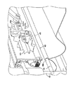
別法として、上記方法を、丸形折り曲げ面を有する折り曲げブレードで実施することができる。ここで使用する「丸形」とは、少なくとも一部に丸形外面(すなわち、何らかの曲率半径)を有することを意味する。たとえば、図3A〜図3C及び図4Cに示された例示的な実施形態では、丸形折り曲げブレード364が単一のロッド状部材として構成されており、丸形折り曲げブレード364の各端部をレール428に固定的に取り付けることができる(図4C)。別法として、丸形折り曲げブレード364は、折り曲げブレード104及びブレードホルダ134に関連して上述したようにして、レール428に沿って移動可能にすることもできる。丸形折り曲げブレード364の折り曲げ面364bは、(図3Aに示されているように)断面をほぼ円形にすることができるが、任意の他の丸形輪郭を有することもできる。折り曲げローラ306及び丸形折り曲げブレード364は、(図3A〜図3Cに示されているように)ほぼ同一の断面積を有することができるが、異なった大きさにすることもできる。
【0028】
別法として、丸形折り曲げブレード364は、折り曲げブレード104のような折り曲げブレードに取り付けることができ、また、折り曲げブレード104と同一材料、または異なった材料のいずれでも製造することができる。丸形折り曲げブレード364は、折り曲げブレードと一体部材として構成することもできるが、折り曲げブレード104に取り付けられる別体の部材にすることもできる。後者の場合、図1A、図1B、図2A〜図2C、図4A及び図4Bに示された実施形態では、丸形折り曲げブレード364を折り曲げブレード104に着脱することができる。また、折り曲げ面364bは、丸形折り曲げブレード364と別体の部材にすることができ、丸形折り曲げブレード364の製造に使用される材料と異なった、または同一の材料で製造することができる。たとえば、丸形折り曲げブレード364は、金属製にすることができる一方、折り曲げ面364bを弾性材料製にすることができる。
【0029】
シート材348を丸形折り曲げブレード364の折り曲げ面364bに、上記のように転動させて押し当てる結果、シート材348に丸形折り目350が形成される。シート材の丸形折り目には、はっきり筋が付いた折り目に勝る幾つかの利点がある。はっきりした折り目が付いたシートの頁は互いに離れる傾向があるが、丸形折り目を付けたシートの頁は、互いに閉じている傾向がある。また、はっきりした折り目を付けたシートからなる冊子は、ピローイングとして知られる効果を示す傾向があり、折り曲げ縁部付近のシート材領域が外向きに跳ねる。丸形折り目は、上記理由(すなわち、丸形折り目はシート頁を互いに閉じる状態に保持する)から、この効果を減少させる。
【0030】
図3Aに示されているように、ハウジング302が、丸形折り曲げブレード364の方へ前進して、(上記折り曲げローラ206と同様に構成して配置されている)折り曲げローラ306が最初に、図3Aに示されているように、シート材348を折り曲げ面364bの上部に押し付ける。折り曲げフラップ218に関連して上述したように、折り曲げフラップ318を使用して、シート材348に折り目350を付け始めることができる。ピンチ足部220に関連して上述したように、ピンチ足部420(図4C)を使用して、シート材348を折り曲げ面364bに当てて固定することができる。
【0031】
別の実施形態の図3B−1及び図3B−2に示されているように、ハウジング302が前進し続けると、丸形折り曲げブレード364の断面形状のために折り曲げローラ306が互いに押し離される。図3B−1の例では、折り曲げローラ306が、折り曲げフラップ318に回転可能に取り付けられており、折り曲げローラ306は互いに近づく方向に付勢されている。たとえば、折り曲げフラップ318は、フラップばね324によってピボット点P3を中心にして互いに近づく方向に回動可能に付勢されている。図3B−1の例では、折り曲げローラ306が折り曲げフラップ318上に取り付けられているので、それらも互いに近づく方向に付勢されており、折り曲げフラップ318が移動する時、ピボット点P3を中心にして回動する。別法として、図3B−2の例では、折り曲げローラ306が折り曲げフラップ318に取り付けられていないで、複数のばね362によって互いに近づく方向に付勢されている。これらの実施形態の両方において、折り曲げローラ306は(すなわち、フラップばね324または複数のばね362によって)互いに近づく方向に付勢されており、したがって、ハウジング302が丸形折り曲げブレード364の方へ進むと、それらはシート材348に接して転動して、それを折り曲げ面364bの周囲に押し付け続ける。
【0032】
図3Cの実施形態は、ハウジング302がy軸方向の前進を完了した時の折り曲げローラ306の位置を示す。この前進中、折り曲げローラ306はシート材348を折り曲げ面364bの大部分に押し付け、それによってシート材348に丸形折り目350を形成する。丸形折り曲げブレード364が折り曲げブレード304またはブレードホルダ334に取り付けられていないが、(図3A〜図3C及び図4Cに示されている)単一ロッドとして構成されている実施形態では、丸形折り曲げブレード364に対する折り曲げローラ306の大きさにもよるが、折り曲げローラ306がシート材348を丸形折り曲げブレード364の表面のほとんどに押し付けることができる(すなわち、各ローラ306は、180度の円弧を回って移動することができる)。ハウジング302は、その前進を完了した後、+y方向に後退し、上記工程が逆の順序になる。このように、シート材348の各シートを折り曲げローラ306によって折り曲げ面364bに2回押し付けることができ、それにより、完全性が高い丸形折り目が確実に得られる。
【0033】
たとえば、TrovingerのPCTに記載されているシート冊子作製システムの場合のように、個々のシートそれぞれの所定の特性を変化させることが時々必要である。丸形折り目を付けた冊子の作製において、各シートの丸形折り目の形状または大きさを変化させることが必要である。たとえば、そのような冊子の最外側、すなわちカバーシートは、最外側シートの頁間に位置するシートの丸形折り目より大きい丸形折り目を必要とするであろう。
【0034】
丸形折り目の大きさ及び/または形状を調節するために、2つの一般的な方法を記載する。1つの方法では、たとえば、完成した冊子内でのシートの位置などの個別シート情報や、折り曲げ済みシートの側部間に位置する他の冊子シートの合計厚さに基づいて、ハウジング302の前進を(たとえば、モータ114に接続された制御ユニットによって)制御する。たとえば、最終的に冊子の最外側シートになるシートに丸形折り目を付けようとする時、折り曲げローラ306がシート材348を折り曲げ面364b全体に押し付けることがない(たとえば、ハウジング302が丸形折り曲げブレード364から後退する前の状態で、シート材348が図3Bに示された程度まで押し付けられるだけである)ように、ハウジング302の前進を制御することができる。このカバーシートの頁間に位置する予定のシートの場合、個別シート情報に応じて、折り曲げローラ306が折り曲げ面364bにより多く押し付けられるように、ハウジング302を前進させることができる。
【0035】
折り曲げ面の大きさ及び/または形状を調節する別の方法は、複数のブレード部分を備えた丸形折り曲げブレード364を使用することを含む。図5A及び図5Bは、2形式の多分割丸形折り曲げブレードの斜視図を示しているが、本発明はこれらの例に制限されない。また、図5A及び図5Bに示された両実施形態は、3つのブレード部分(それぞれブレード部分566及び568)を示しているが、別法としてこの数を2か、あるいは4以上の任意数にすることができる。
【0036】
図5Aの実施形態では、丸形折り曲げブレード564が、分離した複数のブレード部分566を有し、各ブレード部分566は、内側がくさび形で、外側が丸くなっている。3つの部分566を接触するか、ほぼ接触するような位置に置くと、組み合わされた折り曲げ面564bは、円形(または任意の他の丸形)断面形状を有することができる。有効折り曲げ面564bの大きさ及び/または形状を変化させるために、任意の従来型または他の作動手段によって、ブレード部分566を互いに接離するように移動させることができる。たとえば、ブレード部分566間に送りねじまたはくさび状部材を配置して、その間の距離を変更するように制御することができる。図5Bの実施形態では、丸形折り曲げブレード564は、3つのブレード部分568と折り曲げ面564bとを有し、折り曲げ面564bは、ブレード部分568間の距離の変化に伴って形状及び大きさが変化する弾性材料にすることができる。ブレード部分568も、任意の従来型または他の手段によって移動するように制御することができる。これらの例示的な実施形態を使用して、個々のシート情報に従って丸形折り目を生成するように、丸形折り曲げブレード564の大きさ及び/または形状を調節することができる。
【0037】
また、折り曲げ面564bの増加または形状変更を行う他の方法も使用することができる。たとえば、折り曲げ面564bは、(たとえば、折り曲げ面564b内に収容されて制御された流体またはガスからの)内圧の変化に基づいて、大きさ及び/または形状を変化させる弾性円筒室として構成することができる。
【0038】
例示的な実施形態のいずれも、図1Aの例のガイド126のようなガイドでシート材を案内して折り曲げブレードを通過させるステップも含むことができる。ガイド126は、任意の成形可能な材料で形成することができ、図1Aの例では、シート材を折り曲げブレード104の上方へ案内することによって、折り曲げブレード104及びハウジング102間へのシート材の送り込みを助けることができる。言い換えると、ガイド126を使用することによって、シート材の前縁部が折り曲げブレード104の面に接触することを防止することができ、それにより、送り込みステップ中のシート材の詰まりを防止することができる。また、ガイド126は、x軸方向のピボット点P4を中心にして回動し、それにより、折り目を付ける時にガイド126が折り曲げブレード104から離れる(たとえば、回動する)ように構成することができる。この動作は、ガイド126が折り曲げ工程を妨害することを防止し、ハウジング102及びガイド126間に取り付けられたガイドカップリング、たとえば、ガイドカップリング130の使用によって達成することができる。別法として、ガイド126は、任意の他の手段によって、たとえば、非制限的な例として、レール128に沿った直動並進によって、折り曲げブレード104から離れるように構成することができる。また、ガイド126は、ハウジング102が折り曲げブレード104から離れる時、ガイドカップリング130を介して折り曲げ済みシート材を折り曲げブレード104から持ち上げるように機能することができる。
【0039】
加えて、本方法は、スコアリングローラ、たとえば、図1Bの例に示されたスコアリングローラ158でシート材に筋を付けるステップを含むことができる。スコアリングローラ158は、折り曲げブレード304に直交する軸を中心にして回転し、スコアリングモータ160によって駆動することができる。スコアリングローラ158は、TrovingerのPCTに記載されている折り曲げローラと同様に構成することができるが、任意の変更構造にすることもできる。スコアリングローラ158は、折り曲げ動作の前に、シート材の、折り目を付けようとする部分を折り曲げブレード304に当ててロールするように機能する。この動作は、シート材に事前折り目を付けて、たとえば、厚いシート材を折り曲げる時、以後の折り曲げを容易にすることによって役立つことができる。筋付け動作の後、折り曲げ動作を行うために、スコアリングローラ158をハウジング302の経路外へ移動させることができる。筋付け及び折り曲げ動作の両方が共用折り曲げブレード104を使用して行われるので、図1Bに示されたようなスコアリングローラ158の配置は、シート材を置き直すことなく、筋付け及び折り曲げの両動作を可能にする。
【0040】
本発明の例示的な実施形態は、シート材に折り目を付けるように折り曲げローラを単一の軸方向に駆動するために単一のモータを使用するため、低い装置コストでシート材をより迅速に折り曲げることができる。このように、2回の往復移動ではなく、1回のスムーズな動きで折り目を付けることができる。本発明の例示的な実施形態は、すべてが本出願と同日に出願された同時係属出願であって、その開示内容全体が参照によって本明細書に援用される以下の出願、「ピボットアーム折り曲げローラ有するシート折り曲げ装置(Sheet Folding Apparatus With Pivot Arm Fold Rollers)」代理人整理番号第10001418号、「厚い媒体の折り曲げ方法(Thick Media Folding Method)」代理人整理番号第10013508号、「可変媒体厚さ折り曲げ方法(Variable Media Thickness Folding Method)」代理人整理番号第10013507号、及び「丸形折り曲げブレード付きシート折り曲げ装置(Sheet Folding Apparatus With Rounded Fold Blade)」代理人整理番号第10013506号のいずれか、またはすべての特徴を含むように変更することができる。
【0041】
本発明は、その精神または本質的特徴から逸脱することなく、他の特定形状で実施することができることは、当該技術分野の技術者には理解されるであろう。したがって、ここで開示する実施形態は、すべての点で説明的であって、制限的ではないと考えられる。本発明の範囲は、上記説明ではなく、添付の特許請求の範囲によって示されており、それの意味、範囲及び同等物に入るすべての変化は、それに包含されるものとする。
【図面の簡単な説明】
【0042】
【図1A】本発明の例示的な実施形態に従ったシート折り曲げ装置の斜視図である。
【図1B】本発明の例示的な実施形態に従ったシート折り曲げ装置の斜視図である。
【図2A】本発明の別の実施形態による、シート材を折り曲げる工程を示す側面図である。
【図2B】本発明の別の実施形態による、シート材を折り曲げる工程を示す側面図である。
【図2C】本発明の別の実施形態による、シート材を折り曲げる工程を示す側面図である。
【図3A】本発明の別の実施形態による、丸形折り曲げブレードでシート材を折り曲げる工程を示す図である。
【図3B−1】本発明の別の実施形態による、丸形折り曲げブレードでシート材を折り曲げる工程を示す図である。
【図3B−2】本発明の別の実施形態による、丸形折り曲げブレードでシート材を折り曲げる工程を示す図である。
【図3C】本発明の別の実施形態による、丸形折り曲げブレードでシート材を折り曲げる工程を示す図である。
【図4A】図1A、図1B及び図3A〜図3Cのシート折り曲げ装置の破断斜視図である。
【図4B】図1A、図1B及び図3A〜図3Cのシート折り曲げ装置の破断斜視図である。
【図4C】図1A、図1B及び図3A〜図3Cのシート折り曲げ装置の破断斜視図である。
【図5A】本発明の別の実施形態による、複数ブレード部分を有する丸形折り曲げブレードを示す図である。
【図5B】本発明の別の実施形態による、複数ブレード部分を有する丸形折り曲げブレードを示す図である。【Technical field】
[0001]
The present invention relates generally to a sheet folding apparatus that uses a folding roller disposed in a longitudinal direction with respect to a folding blade for folding a sheet material.
[Background]
[0002]
A system for finishing printed sheets into booklets is described in PCT No. WO 00/18583 (hereinafter referred to as Trovinger's PCT), which is incorporated herein by reference in its entirety. Trovinger's PCT includes the operation of folding individual booklet sheets using two drive motor assemblies. A first vertical drive motor assembly functions to secure the sheet by pressing the sheet against the folding blade at the folding assembly. The first vertical drive motor assembly moves a set of folding rollers to a position that contacts both the sheet and the longitudinal folding blade. The axis of rotation of the folding roller is perpendicular to the folding blade used to fold each sheet. Next, the second horizontal drive motor acts to deform the sheet against the folding blade by reciprocating the folding roller set placed in contact with the sheet back and forth along the folding blade. Thus, the sheet is actually creased. The number and spacing of these folding rollers is determined such that during the horizontal movement of the folding rollers, at least one folding roller passes through all points along the portion of the sheet to be creased.
[0003]
The system described in Trovinger's PCT uses two separate motors to make a crease by moving the folding roller linearly in two axes. The time required to crease is the sum of the time to move the folding assembly vertically and the time to move the folding rollers horizontally to crease the sheet.
[0004]
Another folding apparatus is disclosed in US Pat. No. 4,053,150 (Lane), which is incorporated herein by reference in its entirety and is directed to preventing corner folds. The Lane patent includes a blade for pushing paper once folded (eg, folded newsprint) between a pair of rollers, thereby folding the paper into four. The Lane patent uses air flow jets and plates to prevent paper edge and corner folds. However, the Lane patent fails to make accurate and clear creases and to ensure that the paper is properly aligned during the folding process.
[0005]
It would be desirable to reduce equipment costs and the time required to accurately crease the sheet.
DISCLOSURE OF THE INVENTION
[0006]
The present invention is directed to an apparatus for folding a sheet material using a single motor and a folding roller disposed longitudinally with respect to a folding blade.
[0007]
According to an exemplary embodiment of the present invention, there is provided a sheet material folding apparatus, wherein a folding blade, two folding rollers, a pinch foot for pressing the folding blade, and at least one of the folding blade and the folding roller are operated with respect to each other. There is provided a sheet material bending apparatus that includes a driving unit that moves to a communicating state, and in which each of the bending rollers rotates about an axis parallel to the longitudinal axis of the bending blade.
[0008]
According to a second embodiment of the present invention, there is a method for folding a sheet material, the step of feeding the sheet material to an area between two folding rollers and a folding blade, and pressing the sheet material against the folding blade with a pinch foot Moving the folding roller and the folding blade relative to each other, thereby crease the sheet material using the folding blade and moving each folding roller. A method is provided for folding a sheet material that rotates about an axis parallel to the longitudinal axis.
[0009]
Other objects and advantages of the present invention will become more apparent from the following detailed description of the preferred embodiments when read in conjunction with the accompanying drawings, in which like parts are designated with like reference numerals.
BEST MODE FOR CARRYING OUT THE INVENTION
[0010]
An apparatus for folding a sheet material is shown as
[0011]
The folding blade 104 can be formed of metal or any other moldable material and is flat (as shown in FIGS. 1A, 1B, 2A-2C, 4A and 4B). Although it can be molded as a strip, it can also be rounded (shown in FIGS. 3A-3C) and, of course, these examples are non-limiting. For example, alternatively, the cross section of the bending blade 104 (ie, the plane containing the y-axis and z-axis) may be triangular, or the
[0012]
The
[0013]
Each illustrated
[0014]
Driving means such as the driving means 180 of FIGS. 1 and 2 are provided for moving at least the folding blade and the plurality of folding rollers into operable communication with each other. In this specification, “operational communication” means that the folding blade and / or the folding roller are relatively arranged so that a desired crease can be formed in the sheet material. In the exemplary embodiment, drive means 180 includes a coupling such as coupling 116 and an actuator such as
[0015]
The
[0016]
The exemplary coupling 116 has a moving
[0017]
In the exemplary embodiment of FIG. 1A of the present invention, the driving means 180 moves the folding roller along a straight path perpendicular to the sheet material to be folded. For example, when the plurality of moving
[0018]
The
[0019]
As shown in FIG. 2A, each exemplary pinch foot 220 can be attached to the housing with a pinch spring 222, but alternatively any other resilient attachment means can be used. The pinch foot 220 can be formed of any moldable material (metal and plastic are non-limiting examples), or a deformable or elastic material. The pinch foot 220 has a
[0020]
As shown in the cutaway view of the housing 402 in FIG. 4B, the pinch foot 420 is disposed in the gap between the two sub-rollers 446a and 446b. The gap between the
[0021]
The
[0022]
2A to 2C exemplify a method of bending a sheet material. 4A and 4B are a perspective view and a cutaway view, respectively, of the same exemplary embodiment. The method includes feeding a sheet material into an area between at least one roller and a folding blade. This step is illustrated, for example, in FIG. 2A, where the
[0023]
The step of pressing the sheet material against the folding blade with a pinch foot is included in the exemplary method. For example, the pinch foot portion 220 first engages with the
[0024]
The method also includes moving the folding roller and the folding blade relative to each other, whereby the folding blade is used to crease and move the sheet, each folding roller being parallel to the longitudinal axis of the folding blade. Rotate around a specific axis. FIG. 2B shows that the
[0025]
The crease 250 (shown in FIGS. 2B and 2C) is applied by moving the folding roller relative to the folding blade such that the folding blade and sheet material pass between the folding rollers. In the example of FIG. 2B, the
[0026]
FIG. 2C shows the position of the
[0027]
Alternatively, the method can be performed with a folding blade having a round folding surface. As used herein, “round” means having at least part of a round outer surface (ie, some radius of curvature). For example, in the exemplary embodiment shown in FIGS. 3A-3C and 4C, the
[0028]
Alternatively, the
[0029]
As a result of rolling the
[0030]
As shown in FIG. 3A, the
[0031]
As shown in FIGS. 3B-1 and 3B-2 of another embodiment, as the
[0032]
The embodiment of FIG. 3C shows the position of the
[0033]
For example, it is sometimes necessary to change the predetermined properties of each individual sheet, as in the case of the sheet booklet production system described in Trovinger's PCT. In the production of a booklet with a round crease, it is necessary to change the shape or size of the round crease of each sheet. For example, the outermost, or cover sheet, of such a booklet will require a round fold that is larger than the round fold of the sheet located between the pages of the outermost sheet.
[0034]
Two general methods are described for adjusting the size and / or shape of the round fold. In one method, the
[0035]
Another method of adjusting the size and / or shape of the folding surface includes using a
[0036]
In the embodiment of FIG. 5A, the
[0037]
In addition, other methods for increasing or changing the shape of the
[0038]
Any of the exemplary embodiments can also include guiding the sheet material through a folding blade with a guide, such as
[0039]
In addition, the method can include streaking the sheet material with a scoring roller, eg, the scoring
[0040]
The exemplary embodiment of the present invention uses a single motor to drive the folding rollers in a single axial direction to crease the sheet material, thus making the sheet material faster at lower equipment costs. Can be folded. In this way, the crease can be made with one smooth movement instead of two reciprocating movements. Exemplary embodiments of the present invention are co-pending applications, all filed on the same day as this application, the following application, the entire disclosure of which is hereby incorporated by reference: “Pivot Arm Bending Roller” "Sheet Folding Apparatus With Pivot Arm Fold Rollers" Agent No. 10001418, "Thick Media Folding Method" Agent No. 10013508, "Variable Media Thickness Bending Any or all of “Variable Media Thickness Folding Method”, Agent No. 10013507, and “Sheet Folding Apparatus With Rounded Fold Blade”, Agent No. 10013506 Can be modified to include
[0041]
It will be appreciated by those skilled in the art that the present invention may be implemented in other specific forms without departing from the spirit or essential characteristics thereof. Accordingly, the embodiments disclosed herein are considered in all respects as illustrative and not restrictive. The scope of the invention is indicated by the appended claims rather than by the foregoing description, and all changes that come within its meaning, scope and equivalents are intended to be embraced therein.
[Brief description of the drawings]
[0042]
FIG. 1A is a perspective view of a sheet folding apparatus according to an exemplary embodiment of the present invention.
FIG. 1B is a perspective view of a sheet folding apparatus according to an exemplary embodiment of the present invention.
FIG. 2A is a side view showing a process of bending a sheet material according to another embodiment of the present invention.
FIG. 2B is a side view showing a process of bending a sheet material according to another embodiment of the present invention.
FIG. 2C is a side view showing a process of bending a sheet material according to another embodiment of the present invention.
FIG. 3A is a diagram illustrating a process of folding a sheet material with a round folding blade according to another embodiment of the present invention.
FIG. 3B-1 is a diagram illustrating a process of folding a sheet material with a round folding blade according to another embodiment of the present invention.
FIG. 3B-2 is a diagram showing a process of folding a sheet material with a round folding blade according to another embodiment of the present invention.
FIG. 3C is a diagram illustrating a process of folding a sheet material with a round folding blade according to another embodiment of the present invention.
4A is a cutaway perspective view of the sheet folding apparatus of FIGS. 1A, 1B, and 3A to 3C. FIG.
4B is a cutaway perspective view of the sheet folding apparatus of FIGS. 1A, 1B, and 3A to 3C. FIG.
4C is a cutaway perspective view of the sheet folding apparatus of FIGS. 1A, 1B, and 3A to 3C. FIG.
FIG. 5A illustrates a round folding blade having multiple blade portions according to another embodiment of the present invention.
FIG. 5B illustrates a round folding blade having multiple blade portions according to another embodiment of the present invention.
Claims (10)
シート材(248)を2つの折り曲げローラ(106)、及び折り曲げブレード(104)間の領域に送り込むステップと、
前記シート材(248)をピンチ足部(120)で前記折り曲げブレード(104)に押し付けるステップと、
前記折り曲げローラ(106)及び前記折り曲げブレード(104)を相対的に移動させるステップであって、それにより、前記折り曲げブレード(104)を使用して前記シート材(248)に折り目(250)を付ける、移動させるステップとを含み、各折り曲げローラ(106)は、前記折り曲げブレードの長手軸に平行な軸を中心にして回転することを特徴とするシート材を折り曲げる方法。A method of bending a sheet material (248),
Feeding the sheet material (248) into the area between the two folding rollers (106) and the folding blade (104);
Pressing the sheet material (248) against the folding blade (104) with a pinch foot (120);
Moving the folding roller (106) and the folding blade (104) relative to each other, thereby using the folding blade (104) to crease (250) the sheet material (248). A method of folding the sheet material, wherein each folding roller (106) rotates about an axis parallel to the longitudinal axis of the folding blade.
前記シート材(248)をガイド(126)で案内して前記折り曲げブレード(104)を通過させるステップを含み、前記折り目(250)を付ける時、前記ガイド(126)は、前記折り曲げブレード(104)から離れることを特徴とする請求項1に記載のシート材を折り曲げる方法。The feeding step includes:
The sheet material (248) is guided by a guide (126) and passed through the folding blade (104). When the fold (250) is applied, the guide (126) The method of bending a sheet material according to claim 1, wherein the sheet material is bent.
複数のサブローラ(446)を有しており、前記サブローラ(446)及び前記サブローラ(446)間の間隔の合計長さが、少なくとも所望の折り目(250)の長さであることを特徴とする請求項1に記載のシート材を折り曲げる方法。Each folding roller (106)
It has a plurality of sub-rollers (446), and the total length of the interval between the sub-rollers (446) and the sub-rollers (446) is at least the length of the desired fold (250). A method of bending the sheet material according to Item 1.
折り曲げブレード(104)と、
2つの折り曲げローラ(106)と、
前記折り曲げブレード(104)に押し付けるピンチ足部(120)と、
前記折り曲げブレード(104)及び前記折り曲げローラ(106)の少なくとも一方を互いに作動連通する状態に移動させる駆動手段(180)とを備えており、前記折り曲げローラ(106)の各々が、前記折り曲げブレード(104)の長手軸に平行な軸を中心にして回転することを特徴とするシート材折り曲げ装置。A folding device for a sheet material (248) used in the method of claim 1,
A bending blade (104);
Two folding rollers (106);
A pinch foot (120) that presses against the bending blade (104);
Driving means (180) for moving at least one of the folding blade (104) and the folding roller (106) into a state of being in operative communication with each other, and each of the folding rollers (106) 104) A sheet material bending apparatus which rotates about an axis parallel to the longitudinal axis.
カップリング(116)と、
前記カップリング(116)に取り付けられた送りねじ(110)とを有しており、前記送りねじ(110)の第1方向への回転によって、前記折り曲げローラ(106)を移動させて前記折り曲げブレード(104)に当接させることができることを特徴とする請求項7に記載のシート材折り曲げ装置。The drive means (180)
Coupling (116);
A feed screw (110) attached to the coupling (116), and the folding roller (106) is moved by the rotation of the feed screw (110) in a first direction to move the folding blade. The sheet material bending apparatus according to claim 7, wherein the sheet material bending apparatus can be brought into contact with (104).
Applications Claiming Priority (2)
| Application Number | Priority Date | Filing Date | Title |
|---|---|---|---|
| US09/970,730 US6855101B2 (en) | 2001-10-05 | 2001-10-05 | Sheet folding apparatus |
| PCT/US2002/031954 WO2003031304A1 (en) | 2001-10-05 | 2002-10-04 | Sheet folding apparatus |
Publications (2)
| Publication Number | Publication Date |
|---|---|
| JP2005507837A true JP2005507837A (en) | 2005-03-24 |
| JP2005507837A5 JP2005507837A5 (en) | 2006-01-05 |
Family
ID=25517419
Family Applications (1)
| Application Number | Title | Priority Date | Filing Date |
|---|---|---|---|
| JP2003534296A Pending JP2005507837A (en) | 2001-10-05 | 2002-10-04 | Sheet folding device |
Country Status (5)
| Country | Link |
|---|---|
| US (1) | US6855101B2 (en) |
| EP (1) | EP1432634B1 (en) |
| JP (1) | JP2005507837A (en) |
| DE (1) | DE60205764T2 (en) |
| WO (1) | WO2003031304A1 (en) |
Cited By (2)
| Publication number | Priority date | Publication date | Assignee | Title |
|---|---|---|---|---|
| JP2014136414A (en) * | 2013-01-18 | 2014-07-28 | Mitsubishi Electric Corp | Insulating film molding machine and insulating film molding method |
| JP2015209329A (en) * | 2014-04-30 | 2015-11-24 | コニカミノルタ株式会社 | Sheet binding device and image formation system |
Families Citing this family (11)
| Publication number | Priority date | Publication date | Assignee | Title |
|---|---|---|---|---|
| EP1117540B1 (en) * | 1998-09-29 | 2004-03-03 | Hewlett-Packard Company, A Delaware Corporation | Method and apparatus for making booklets |
| US7033123B2 (en) * | 2002-02-28 | 2006-04-25 | Hewlett-Packard Development Company, L.P. | Booklet maker |
| US6981830B2 (en) * | 2002-02-28 | 2006-01-03 | Hewlett-Packard Development Company, L.P. | Pivotable collecting device |
| US6837841B2 (en) * | 2002-09-30 | 2005-01-04 | Hewlett-Packard Development Company, L.P. | Method and apparatus for sheet folding |
| US6997450B2 (en) * | 2003-10-09 | 2006-02-14 | Hewlett-Packard Development Company, L.P. | Sheet folding and accumulation system for a booklet maker |
| US20060022393A1 (en) * | 2004-07-30 | 2006-02-02 | Trovinger Steven W | Method of sheet accumulation using sideways saddle motion |
| US7503554B2 (en) * | 2005-11-30 | 2009-03-17 | Hewlett-Packard Development Company, L.P. | Book finishing station with heating element and method of use |
| US7819615B2 (en) | 2005-12-06 | 2010-10-26 | Hewlett-Packard Development | Method and apparatus for finishing sheets for a bound document |
| US7857442B2 (en) * | 2008-10-20 | 2010-12-28 | Xerox Corporation | Heated folding system for a phase change ink imaging device |
| JP5954151B2 (en) * | 2012-12-12 | 2016-07-20 | 富士ゼロックス株式会社 | Recording material processing apparatus and recording material processing system |
| CN110799329B (en) * | 2017-09-27 | 2021-10-08 | 三菱重工机械系统株式会社 | Paperboard folding device and box making machine |
Family Cites Families (56)
| Publication number | Priority date | Publication date | Assignee | Title |
|---|---|---|---|---|
| US1215613A (en) * | 1914-02-12 | 1917-02-13 | Benjamin Clayton | Baling-press. |
| US1840319A (en) * | 1926-08-20 | 1932-01-12 | Wood Newspaper Mach Corp | Folder roller adjusting device |
| US2493410A (en) * | 1945-09-07 | 1950-01-03 | Orchard Paper Company | Apparatus for folding paper sheets |
| US3202066A (en) * | 1962-10-11 | 1965-08-24 | Monsanto Co | Apparatus and method for folding synthetic plastic sheet stock |
| US3434399A (en) * | 1966-07-29 | 1969-03-25 | Jones & Laughlin Steel Corp | Process for scoring and folding steel foil-paperboard laminates |
| US3398661A (en) * | 1966-09-20 | 1968-08-27 | Procter & Gamble | Frame blank forming machine |
| US3995849A (en) * | 1970-08-17 | 1976-12-07 | Hermann Kistner | Sheet folding machine with rollers and a pocket |
| US3711086A (en) * | 1970-09-01 | 1973-01-16 | H Weist | Method and apparatus for folding lengths of material |
| US3916749A (en) * | 1973-06-05 | 1975-11-04 | Georges Edouard Armelin | Rotary cutting and fold marking tool |
| US3926425A (en) * | 1974-06-27 | 1975-12-16 | Kimberly Clark Co | Method of coupon positioning and mechanism therefor |
| DE2451469C3 (en) * | 1974-10-30 | 1979-05-23 | Bay, Otto, Dipl.-Ing., Subingen (Schweiz) | Method and device for producing a folded sheet of paper, film or the like |
| US3978773A (en) * | 1974-11-29 | 1976-09-07 | Albert Anthony Pinto | Package liner forming and feeding apparatus |
| US3954258A (en) * | 1975-03-24 | 1976-05-04 | Rockwell International Corporation | Second fold roller mounting and adjustment means |
| FR2317092A1 (en) * | 1975-07-11 | 1977-02-04 | Shinko Kikai Seisakusho | METHOD AND APPARATUS FOR FOLDING CARDBOARD SHEETS |
| US4053150A (en) * | 1976-03-08 | 1977-10-11 | Cornelius Printing Co. | Folder apparatus |
| US4101121A (en) * | 1977-02-09 | 1978-07-18 | Pitney-Bowes, Inc. | Document folding apparatus |
| CH615646A5 (en) * | 1977-03-18 | 1980-02-15 | Grapha Holding Ag | |
| CH623289A5 (en) * | 1977-10-24 | 1981-05-29 | Ferag Ag | |
| US4226410A (en) * | 1978-04-20 | 1980-10-07 | Centronics Data Computer Corporation | Stacking system for fanfold paper and the like |
| US4310326A (en) * | 1979-08-23 | 1982-01-12 | Bellanca Joseph V | Apparatus for folding paper |
| US4419088A (en) * | 1981-06-19 | 1983-12-06 | Nemec David G | Gate folding apparatus |
| FR2520665B1 (en) * | 1982-02-04 | 1987-12-24 | Martin Sa | PLAQUE FOLDING MACHINE |
| SE431975B (en) * | 1982-04-22 | 1984-03-12 | Dynasonic | DEVICE FOR FOLDING A SHEET TO A FOLDER |
| US4496339A (en) * | 1983-04-18 | 1985-01-29 | Moll Richard J | Apparatus for setting roller clearance |
| US4595187A (en) * | 1985-07-26 | 1986-06-17 | Xerox Corporation | Saddle stapler accessory |
| US4643705A (en) * | 1985-07-29 | 1987-02-17 | Xerox Corporation | Positive drive knife folder |
| SE451261B (en) * | 1986-01-08 | 1987-09-21 | Mo Och Domsjoe Ab | DEVICE FOR DOUBLEVIKA A FLEXIBLE PRODUCT |
| DE3601660A1 (en) * | 1986-01-21 | 1987-07-23 | Eltex Elektrostatik Gmbh | METHOD AND DEVICE FOR FOLDING SHEETS CUT FROM A CONTINUOUS MATERIAL |
| US4834696A (en) * | 1987-09-30 | 1989-05-30 | Marquip, Inc. | Folding of paperboard sheets and the like |
| US4891681A (en) | 1988-12-09 | 1990-01-02 | Eastman Kodak Company | Hard copy apparatus for producing center fastened sheet sets |
| US5028193A (en) * | 1989-04-26 | 1991-07-02 | Misicka James A | Saddle-bound books, magazines and the like and process for manufacture same |
| US5080339A (en) * | 1989-05-29 | 1992-01-14 | Mitsubishi Jukogyo Kabushiki Kaisha | Folding machine of a rotary press |
| US5114392A (en) * | 1989-09-28 | 1992-05-19 | The International Paper Box Machine Co., Inc. | Apparatus for folding paper boxes |
| US5092827A (en) * | 1989-09-28 | 1992-03-03 | International Paper Box Machine Co., Inc. | Apparatus for folding paper boxes |
| DE4020937C2 (en) * | 1990-06-30 | 1996-07-11 | Koenig & Bauer Albert Ag | Longitudinal folding device |
| WO1992002888A1 (en) | 1990-07-27 | 1992-02-20 | Ross Harvey M | System and method of manufacturing a single book copy |
| US5145158A (en) * | 1990-09-07 | 1992-09-08 | Mim Industries, Inc. | Method and apparatus for attaching binding to extensible material |
| US5152654A (en) | 1990-10-04 | 1992-10-06 | Minnesota Mining And Manufacturing Company | Hot melt adhesive applicator |
| CH682064A5 (en) | 1990-10-24 | 1993-07-15 | Kolbus Gmbh & Co Kg | |
| DE4101399A1 (en) * | 1991-01-18 | 1992-07-23 | Kodak Ag | DEVICE FOR FOLDING LEAFS |
| EP0511488A1 (en) * | 1991-03-26 | 1992-11-04 | Mathias Bäuerle GmbH | Paper folder with adjustable folding rollers |
| US5190514A (en) * | 1991-10-11 | 1993-03-02 | Profold, Inc. | Gap control apparatus for fold roller |
| US5230686A (en) * | 1992-08-19 | 1993-07-27 | International Paper Box Machine Co., Inc. | Apparatus for folding paper boxes |
| US5377965A (en) * | 1993-11-08 | 1995-01-03 | Xerox Corporation | Automatic on-line signature booklets finisher for electronic printers |
| US5452920A (en) | 1994-02-16 | 1995-09-26 | Parker; Kevin P. | Adhesive binding strip and method of making the same |
| DE4439198A1 (en) * | 1994-11-06 | 1996-05-09 | Klett Alfred | Device for processing a blank conveyed along a conveying path with a predetermined conveying speed |
| DE19543152C2 (en) * | 1995-11-18 | 1999-09-02 | Kodak Ag | Device for folding sheets |
| US5803891A (en) * | 1996-02-01 | 1998-09-08 | Moore Business Forms, Inc. | Apparatus of accumulating sheets for a booklet |
| JP3028204B2 (en) | 1996-06-20 | 2000-04-04 | 株式会社バルダンソーイングマシン | Three winding method for edge sewing of long fabric and three winding device used therefor |
| US6094225A (en) * | 1997-12-02 | 2000-07-25 | Daewoo Electronics, Co., Ltd. | Method and apparatus for encoding mode signals for use in a binary shape coder |
| US5937757A (en) * | 1998-01-07 | 1999-08-17 | Goss Graphic Systems, Inc. | Gap adjusting device with pressure relief for a second fold roller |
| US5957823A (en) * | 1998-01-13 | 1999-09-28 | Fan; K. S. | Folding mechanism for a bag knitting apparatus |
| EP1117540B1 (en) * | 1998-09-29 | 2004-03-03 | Hewlett-Packard Company, A Delaware Corporation | Method and apparatus for making booklets |
| JP3744234B2 (en) | 1998-11-10 | 2006-02-08 | コニカミノルタホールディングス株式会社 | Sheet post-processing apparatus and image forming apparatus |
| US6090032A (en) * | 1999-03-19 | 2000-07-18 | Joseph V. Bellanca Revocable Trust | Apparatus for folding paper |
| US6193458B1 (en) | 1999-04-29 | 2001-02-27 | Jeffrey D. Marsh | System for and method of binding and trimming a perfect bound book |
-
2001
- 2001-10-05 US US09/970,730 patent/US6855101B2/en not_active Expired - Lifetime
-
2002
- 2002-10-04 WO PCT/US2002/031954 patent/WO2003031304A1/en active IP Right Grant
- 2002-10-04 DE DE60205764T patent/DE60205764T2/en not_active Expired - Fee Related
- 2002-10-04 JP JP2003534296A patent/JP2005507837A/en active Pending
- 2002-10-04 EP EP02778457A patent/EP1432634B1/en not_active Expired - Fee Related
Cited By (2)
| Publication number | Priority date | Publication date | Assignee | Title |
|---|---|---|---|---|
| JP2014136414A (en) * | 2013-01-18 | 2014-07-28 | Mitsubishi Electric Corp | Insulating film molding machine and insulating film molding method |
| JP2015209329A (en) * | 2014-04-30 | 2015-11-24 | コニカミノルタ株式会社 | Sheet binding device and image formation system |
Also Published As
| Publication number | Publication date |
|---|---|
| US6855101B2 (en) | 2005-02-15 |
| EP1432634A1 (en) | 2004-06-30 |
| DE60205764T2 (en) | 2006-06-29 |
| DE60205764D1 (en) | 2005-09-29 |
| WO2003031304A1 (en) | 2003-04-17 |
| US20040048728A1 (en) | 2004-03-11 |
| EP1432634B1 (en) | 2005-08-24 |
Similar Documents
| Publication | Publication Date | Title |
|---|---|---|
| US6673002B2 (en) | Sheet folding apparatus with pivot arm fold rollers | |
| JP2005507837A (en) | Sheet folding device | |
| JP2004345863A5 (en) | ||
| US6939284B2 (en) | Sheet folding apparatus with rounded fold blade | |
| US6878104B2 (en) | Variable media thickness folding method | |
| US8419003B2 (en) | Creasing device and image forming system | |
| US6808479B2 (en) | Thick media folding method | |
| JP2871858B2 (en) | Method and apparatus for vertical folding | |
| US6916281B2 (en) | Method and apparatus for sheet folding | |
| JP2006159894A (en) | Center fold booklet square back shaping apparatus | |
| EP3925744A1 (en) | A perforation device for a document processing machine | |
| JP3552312B2 (en) | Sheet material cutting device | |
| JP3735477B2 (en) | Packaging machine feeding device for packaging machine | |
| JPH08257987A (en) | Method and device for cutting elastic long sheet | |
| JPH02182667A (en) | High speed folding machine for elastic material band | |
| JP2010036403A (en) | Booklet forming apparatus and booklet forming method | |
| CN106863077A (en) | Finishing belting and workpiece method for fine finishing | |
| JPH05493U (en) | Paper press mechanism of paper moving probing plotter | |
| JPH07309526A (en) | Continuous paper sheet folding device |
Legal Events
| Date | Code | Title | Description |
|---|---|---|---|
| A521 | Written amendment |
Free format text: JAPANESE INTERMEDIATE CODE: A523 Effective date: 20050929 |
|
| A621 | Written request for application examination |
Free format text: JAPANESE INTERMEDIATE CODE: A621 Effective date: 20050929 |
|
| A131 | Notification of reasons for refusal |
Free format text: JAPANESE INTERMEDIATE CODE: A131 Effective date: 20071113 |
|
| A02 | Decision of refusal |
Free format text: JAPANESE INTERMEDIATE CODE: A02 Effective date: 20080408 |