JP2005506639A - Sensing device - Google Patents
Sensing device Download PDFInfo
- Publication number
- JP2005506639A JP2005506639A JP2003538976A JP2003538976A JP2005506639A JP 2005506639 A JP2005506639 A JP 2005506639A JP 2003538976 A JP2003538976 A JP 2003538976A JP 2003538976 A JP2003538976 A JP 2003538976A JP 2005506639 A JP2005506639 A JP 2005506639A
- Authority
- JP
- Japan
- Prior art keywords
- rolling element
- sensing device
- indicator means
- magnetic field
- instrument
- Prior art date
- Legal status (The legal status is an assumption and is not a legal conclusion. Google has not performed a legal analysis and makes no representation as to the accuracy of the status listed.)
- Pending
Links
Images


Classifications
-
- G—PHYSICS
- G06—COMPUTING; CALCULATING OR COUNTING
- G06F—ELECTRIC DIGITAL DATA PROCESSING
- G06F3/00—Input arrangements for transferring data to be processed into a form capable of being handled by the computer; Output arrangements for transferring data from processing unit to output unit, e.g. interface arrangements
- G06F3/01—Input arrangements or combined input and output arrangements for interaction between user and computer
- G06F3/03—Arrangements for converting the position or the displacement of a member into a coded form
- G06F3/033—Pointing devices displaced or positioned by the user, e.g. mice, trackballs, pens or joysticks; Accessories therefor
- G06F3/0354—Pointing devices displaced or positioned by the user, e.g. mice, trackballs, pens or joysticks; Accessories therefor with detection of 2D relative movements between the device, or an operating part thereof, and a plane or surface, e.g. 2D mice, trackballs, pens or pucks
- G06F3/03545—Pens or stylus
- G06F3/03546—Pens or stylus using a rotatable ball at the tip as position detecting member
Abstract
表面に対する本体の並進運動を検出する感知装置である。該装置は、使用時に上記表面と接触する転動要素を有し、該転動要素は上記本体により保持されると共に、使用時に該本体とは独立に回転可能である。該装置は、更に上記転動要素と関連付けられると共に該回転要素と一緒に回転可能な1以上のインジケータ手段と、1以上のトランスジューサであって、該1以上のトランスジューサに対する上記インジケータ手段の回転に応答して1以上の信号を生成する1以上のトランスジューサとを有する。使用時において、上記転動要素は表面に対する上記本体の相対並進運動に応答して該表面上を転動し、これにより、上記インジケータ手段の位置的向きを上記トランスジューサに対して変化させる。A sensing device that detects the translation of the body relative to the surface. The device has a rolling element that contacts the surface during use, the rolling element being held by the body and rotatable independently of the body during use. The apparatus further includes one or more indicator means associated with the rolling element and rotatable with the rotating element, and one or more transducers responsive to rotation of the indicator means relative to the one or more transducers. And one or more transducers for generating one or more signals. In use, the rolling element rolls on the surface in response to the relative translation of the body relative to the surface, thereby changing the positional orientation of the indicator means relative to the transducer.
Description
【技術分野】
【0001】
本発明は感知装置に係り、特には、表面に対する本体の並進運動を検出する感知装置に関する。
【背景技術】
【0002】
従来既知のセンサは、運動自体又は1以上の方向への特定の運動の何れかを検出していた。このようなセンサは、手持ち装置内に組み込まれている。
【0003】
ユーザがコンピュータにより発生される環境と対話するのを可能にする良く知られた手持ち入力装置は、タッチスクリーン、トラックボール、マウス、ジョイスティック、グローブ、スタイラスを備えるデジタル化(離散化)タブレット及び電子書込ボード上で対話するライトペンを含む。これらの多くは、主に“使い易い”ように設計されており、従って斯かる装置を方向制御又はカーソルの指し示しに使用することのみができる程度の精度を有している。これら装置の多くは、自然な書き込み姿勢で使用することはできず、従って、書き込まれた文字又は形状に関する捕捉し及び更に解析することができるような情報を容易に発生することはできない。
【0004】
ライトペン又はデジタル化タブレットのような自然な書き込み姿勢で保持することが可能な装置は、情報を発生するためには2つの別個の部分を使用することによってのみ使用することができ、その場合に、これら部分は繋がれるか又は無線であるので、斯かる装置は携帯装置として使用するには(即ち、ユーザが移動する場合には)高価、面倒であり、実用的でない。
【発明の開示】
【発明が解決しようとする課題】
【0005】
従って、本発明の目的は、スタイラス又はペンのような手持ち装置内で使用することができ、書き込まれた文字又は形状に関する情報を発生させるために自然な書き込み姿勢で使用することができるような感知装置を提供することにある。
【課題を解決するための手段】
【0006】
本発明によれば、表面に対する本体の並進運動を検出する感知装置であって、
使用時に上記表面と接触する転動要素であって、上記本体により保持されると共に、使用時に該本体とは独立に回転することが可能な転動要素と、
上記転動要素と関連されると共に該転動要素と一緒に回転可能な1以上のインジケータ手段と、
1以上のトランスジューサであって、該1以上のトランスジューサに対する上記インジケータ手段の回転に応答して、1以上の信号を生成する1以上のトランスジューサと、
を有し、前記転動要素は使用時に前記表面に対する前記本体の相対並進運動に応答して前記表面上を転動し、これにより、前記インジケータ手段の位置又は向きを前記トランスジューサに対して変化させるような感知装置が提供される。
【0007】
前記インジケータ手段は前記転動要素内の永久的又は一時的磁場とすることができ、該磁場は異方性の又は不均一なものであり得る。
【0008】
上記インジケータ手段は、上記転動要素の外部の手段により発生することができるが、該転動要素の表面の特性により変化させることができる。例えば、上記インジケータ手段は上記転動要素の表面上の被覆とすることができ、該被覆は活性源により活性化される。該被覆は、燐光性、サーモクロミック又は熱性(thermal)なものとすることができる。上記活性化手段は光源、熱源又は磁場発生器とすることができる。上記活性源はパルス型とすることができる。
【0009】
代替的に又は追加的に、上記インジケータ手段は上記転動要素の表面のマーキングを含むことができる。
【0010】
上記インジケータ手段は過渡的な場に基づくものとすることができ、斯かる過渡場は上記転動要素の一部に誘起されるようにすることができると共に、時間にわたり減衰する。これは、磁場又は減衰する電荷とすることができる。
【0011】
上記1以上のトランスジューサは、該トランスジューサに対する上記インジケータ手段の相対的回転に応答して信号を発生する磁場センサ、電荷センサ又は光センサを含むことができる。該トランスジューサにより発生された信号は、感知された特性に比例するものとすることができ、又は閾値に対して双安定的なものとすることができる。
【0012】
上記転動要素の表面は磁化可能な物質の表面被覆を含むことができ、該表面被覆を磁化する手段及び当該トランスジューサが関連の信号を発生した後に該磁化を除去する消去手段が存在してもよい。上記消去装置は、永久的にオンされたものとすることができる。
【0013】
上記転動要素の表面上の又は斯かる表面内の双極子のアレイのような、該転動要素の表面の所定の磁化パターンが存在してもよい。他の例として、該転動要素自体が1以上の双極子を含むこともできる。
【0014】
上記転動要素は、好ましくは、炭化タングステンから形成される。
【0015】
当該装置は、表面から持ち上げられた場合に上記転動要素の運動の一時的中断を検出する手段を含むことができ、該手段は圧力センサとすることができる。
【0016】
感知される単一の回転軸のみが存在するようにすることができる。
【0017】
また、本発明は上述した感知装置を含むような器具も含み、その場合において、感知装置は当該器具の先端に配置されると共に、該先端の表面上における運動を追跡するために使用される。
【0018】
また、本発明は上述した感知装置を含むような器具も含み、その場合において、前記転動要素は当該器具の感知点に配置されると共に、該感知点に対する表面の運動を感知及び追跡するために使用される。
【0019】
上記器具の何れにおいても、上記先端にはインクを供給することができ、次いで該インクは上記転動要素が上記表面に沿って移動するにつれ、該表面上に付着される。この場合、当該器具は組込センサを備える筆記器具となる。
【0020】
現在の好ましい例においては、球状物体の位置を検出する方法は、該球状物体に関連する磁場を検出する。この転動する物体の運動に関する情報を推定するためには、該転動する物体がセンサのサンプルの間において1以上の完全な回転を達成することができないような充分に高い頻度でサンプルされることを保証することが必要である。
【0021】
この技術は、如何なる軸の廻りにも何の制限もなく回転する自由度を有するような転動物体に適用することができ、限られた運動の範囲を有する関節連結にも適用することができる。2以上の軸における運動を検出するには複数のセンサ(自由度当たり少なくとも1つのセンサ)が必要となる。
【0022】
上記転動物体の位置は、該物体の周りの複数の位置において磁場を測定することにより検出される。これは、異方性磁気抵抗(AMR)センサ又は磁場強度を検出する他のセンサを用いることにより達成することができる。これは、球状物体の動きというよりは位置を検出することができるという点で磁場の変化率を検出するような技術を凌駕する利点を有し、このような機能は、この技術が多くの用途に適用されることを可能にする。当該ボールは、自身の位置が決定されるために動いている必要はない。また、上記センサからの信号を処理することにより、回転速度及び加速も直接的に利用可能となる。
【0023】
この技術は、以下のような永久磁場の1つを持つ転動物体と共に使用することができる:
単純な磁気双極子。これは、球状物体に印加する磁場が最も単純で且つ最も安価であるという利点を有している。加えて、所与の大きさの球状物体に対する磁場強度が、この形態の磁化に関しては最大となるであろう。
【0024】
湾曲磁気双極子。これは、単純な双極子に関連する軸方向の縮退を除去するという利点を有している。これは、球状物体が磁軸の廻りに回転し得、従って当該センサにより測定される如何なる磁場の変化も除去し得るという事態が除去されることを意味する。
【0025】
複数磁区:四極子及び複数極。四又は複数の極を持つ球状物体を作製することは、単一の双極子(真っ直ぐな又は湾曲された)を作製することよりも一層複雑であるが、この磁場パターンは球状物体の位置の一層精細な分解能を提供するという利点を有している。
【0026】
好ましいセンサ装置は、殆どが又は全体として球状の磁化された本体(例えば、前者はボール・ソケット型関節連結体であり得、後者は自由なボールであり得る)を組み込んでいる。
【0027】
後者の場合、上記ボールが回転することができるように、該ボールが自由に回転するのを可能にするようなベアリング内に保持されることを要する。この場合、該ボールは印加される如何なる回転的乱れに対しても応答し得る。上記ベアリングは、滑らかな及び/又は信頼性のある動作を補助するために何らかの形の静又は動圧流体潤滑を付加的に必要とし得る。
【0028】
例えば、質量中心が当該ボールの物理的中心にないような球は傾きセンサとして動作し得る。他の例として、ボールペン又は1若しくは2次元平行移動エンコーダにおけるように、ボールが表面に押圧されて回転することができ、ベアリングが該表面に対して移動される。
【0029】
ボールハウジングがハウジング内でバネ支持されている場合は、第3次元(z)における位置及び運動も検出することができる。
【0030】
このアナログ系における所要の精度を達成するために、ボールの向きを見付けるべくセンサ及び該ボールの相対位置は固定され且つ良好に制御されることを要する。
【0031】
これを固定するために、上記ボールハウジングの正確な加工を用いることができるが、多くの場合において、該ハウジングは実際には使用中に摩耗するので、ボール及び該ボールのハウジングをセンサアセンブリから分離するのが有利であろう。これは、摩耗した部分の容易な交換を可能にする。
【0032】
当該系が2つの部分を有する場合(一方としてハウジング内のボール、他方としてセンサアセンブリ)、これら2つの構成部品の互いの間の正確な位置決めに対する要件が存在する。拘束の運動理論の原理を用いれば、上記ボール用のベアリングを6つの自由度のうちの3つ(平行移動のもの)において拘束することのみが必要であるが、実際には、幾何学構造が与えられると、その自由度の6つ全てが動作時に拘束されることになる。
【0033】
ボールハウジングにおける相補的な構造と一緒に、センサアセンブリにおいては該ボールハウジングが所定位置に押し込まれると共にロックされるのを可能にするような構造が必要とされる。
【0034】
一例として2つの面(例えばx及びy)において回転対称な構造をとると、3つの接触点が該面を拘束する。第3の面における相手の基準面が当該拘束を完成させる。基準面を押し合わせると共に、それらの相対位置を維持するためのメカニズムが必要である。これの一例は、差込口金金具(バイオネット口金嵌め込み:bayonet cap fitting)である。
【0035】
本発明の感知装置を組み込む製品は、機能的に、テキスト、又はグラフィックス、又は速度プロファイル入力からの範囲のものとなるであろう。
【発明を実施するための最良の形態】
【0036】
以下、本発明の実施例を、添付図面を参照して説明する。
【0037】
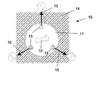
図1において、感知装置10は、双極子12により磁化された球状ボール11を有している。該ボールは、典型的には、直径が700〜1000μmである。該ボールは、100μmなる典型的な壁厚のハウジング(図示略)内に保持され、該ハウジングには3つの磁場センサ13が取り付けられている。これらセンサ13は、ボール11の表面から約200μmにある。使用時において、ボール11は、本体が表面14に対して移動されるにつれて該ボール11が磁場センサ13に対して回転するように、表面14に接触させられる。このようにして、上記双極子の向きが変化し、これにより当該ボールの周りの磁場を変化させる。この変化はセンサ13により検出される。センサ13は、該検出された場の変化を、連続的に変化可能な出力信号15に変換する。
【0038】
上記磁場センサ13は、本例では、薄膜トランスジューサである。本例においては、ボール11の動きを決定するために3つのセンサが好ましい。残りの図の説明においては、同様の特徴に関しては同一の符号が使用されている。
【0039】
図3及び4に示される第2実施例は、ボール11上の異なる形態の磁場を示している。この場合、ボール11は不均一に磁化されており、これが磁界線16により示されている。勿論、これら磁界線は如何なる好適な形態のものとすることもできる磁場の概念的表現である。本例では、ボール11がセンサ13に対して回転するにつれて、磁場の変化がセンサ13により検出される。
【0040】
ボール11の表面における磁場強度は、該ボール11が形成される材料に依存して、典型的には1ないし100ガウス程度である。
【0041】
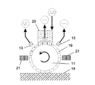
本発明の第3実施例が図5及び6に示され、該実施例においてボール11は異方性の又は不均一な透磁率を備えている。該ボールは元々(本来的に)磁化されていても、そうでなくてもよい。永久的又は切り換え可能な電磁石18のアレイがボール11の周りに離隔配置されて、該ボール11に印加される磁場の強度を制御する。この構成においては、上記電磁石は表面14と略平行であると共にボール11の略中間点にある面内に配置されている。
【0042】
図7及び8は第4実施例を示し、該実施例においてボール11には例えば磁気テープにおけるような酸化第二鉄等の磁化可能な材料の表面被覆19が設けられている。図8から分かるように、平面視でボール11の中心上に配置された書込ヘッド20が、上記表面層19上に磁化領域22を付与する。この磁化領域は、ボール11が回転するにつれてセンサにより検出される。該領域は、消去ヘッド21により供給される消去磁場に暴露されると消去される。本例では、消去ヘッド21は永久的にオン状態であるが、これらヘッドは必要な場合にのみ活性化されるように制御することもできる。ボール11の回転速度が読出ヘッド信号の強度を決定し、回転の方向はセンサ信号の間の相関により与えられる。
【0043】
図9及び10に示す第5実施例は、上記第4実施例におけるように中央に配置された書込ヘッド20を示し、赤道状消去ヘッド21を備えている。本例では、書込ヘッド20はパルス駆動されて、表面磁気の二進パターン23を生成する。本例では、センサ13からの出力信号15もパルス状である。
【0044】
図11及び12において、第6実施例におけるボール11には表面被覆19に所定のパターンの磁化が、該表面が個別双極子のアレイを有するように設けられている。センサ13は、ボール11が回転されるにつれて、上記所定パターンの双極子の移動を検出することができる。読み取りの精度を向上させるために、オプションとしての中央の“基準”センサ24を設けることもできる。
【0045】
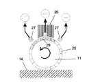
図13及び14に示す第7実施例は、表面活性化可能な被覆25が設けられたボール11を有している。該被覆は、燐光性、サーモクロミック又は熱性(thermal)なものとすることができ、熱源又は光源であり得るような活性源26により活性化される。センサ27は、上記活性源に応じて熱センサ又は光センサの何れかとすることができる。上記活性源は、典型的には中実又は中空の管28に取り付けられ、ボール11の表面上に上記センサにより検出することが可能な局在化された活性領域29を形成する。該活性化は既知のレートで減衰し、これを、ボール11の回転方向及び速度を決定するために使用することができる。
【0046】
図15及び16に示される第8実施例は、上記第7実施例のものと同一であるが、この構成においては、上記活性源がパルス駆動されて、ボール11の表面上に異なる形状の活性化領域を形成する。
【0047】
図17のAないし17のF及び図18に示す第9実施例は、ボール11の表面上のパターンを検出するための光学センサ30を有している。図17のBないしFに示すような異なる形態のパターンは、各々、ランダム、市松模様、ラインパターン又はマイクロコードであり得る。
【0048】
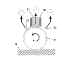
図19及び20は本発明の第10実施例を示し、該実施例においては、インク31がボール11に供給されると共に以前の筆記器具から既知の態様で表面14上に被着することができる。しかしながら、本例においては、活性源32が設けられ、例えば熱、光又は磁場を用いてインク温度、燐光性又は当該インク内の粒子の磁気整列を変えるようにして、該インクの特性を変化させる。センサ33は、上記活性化を検出するために要する如何なる形態のものでもあり、当該ボールが回転するにつれて上記活性化の減衰による該活性化の場の変化を検出する。
【0049】
特に、上記インクは、該インクがボール11上に引き出される際に活性源32により局部的に配向される磁化可能な粒子を含むことができる。この場合、上記検出は磁気センサによるものとなるであろう。上記磁気配列は当該インクが表面14に受け渡された場合に失われるであろう。図示されていないが、ボール11の回転の指示情報を得るためにインク膜の厚さを検出することも考えられ、これは、インクの透過性(permeability)に基づいて容量的に実施することができるか、又はインクの光学濃度に基づいて光学的に実施することができる。
【0050】
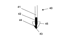
図21及び22は、図19及び20に示したセンサ装置を用いた筆記器具に使用することができる先端の概略構成を示している。
【0051】
特に、図21及び22は詰め替え先端部40を示し、該詰め替え先端部はインクの供給のための詰め替えカートリッジ41及び黄銅の先端インサート42を含んでおり、該インサートを介してインクは先端43に流れることができる。トランスジューサ44は、当該詰め替え体の周のまわりに間隔をあけて設けられ、筆記器具の先端ケーシング45内に填り込むように整形されている。
【0052】
図23及び24は、手書きをホストプロセッサ上のアプリケーション内に現れるタイプ入力テキストに変換する器具50を示している。ローラーボール51は標準のローラーボールインク詰め替え53内に収容され、該詰め替えは、図27A及び27Bに示すように、当該ペン本体内に配置されるセンサ52に対して正確に保持される。センサ52は、キャリア66上に取り付けられ、エポキシ(チバガイギ2019)内に封入され、プラスチックの保護円錐シュラウド54内に収容される。
【0053】
ローラーボール51はラブアロイ(Ruballoy)、即ち炭化タングステンの標準的合金(72%のWC、20%のCo及び5%のCrを含む)から形成される。該ボールは典型的には1.0mmの直径である。該ローラーボールは、電磁コイルにより発生される飽和線形磁場に暴露することにより、組立前に一様な双極子で磁化される。
【0054】
詰め替え体53の一方の端部におけるローラーボールハウジング53aは、黄銅、即ち非磁性である標準のペン先端材料である。インク63が流れ、且つ、上記ローラーボールが回転するのを可能にするために、ローラーボール51とハウジング53aとの間には僅かな量の空き空間65が存在する。
【0055】
ローラーボールハウジング53aは、ローラーボールが当該ハウジング内に係留されるように、該ローラーボールを少し赤道を越えて閉じ込める。
【0056】
センサ52は、ブリッジ構成で使用される異方性磁気抵抗(AMR)センサである。磁場強度は、これらAMRセンサのうちの複数を含むブリッジに電圧を印加すると共に、発生された電圧オフセットを測定することにより検出することができる。
【0057】
本例では、3つのセンサが使用される。これらセンサは、当該ペンの長軸の周りに回転対称的に、該軸に45度の角度で、当該センサの活性面が該ローラーボールの中心に向けられた状態で配設される。
【0058】
センサ52は、センサ位置からキャリア66を介して主ペン本体56内に繋がる導体55を用い、コネクタ57を介してPCB67に電気的に接続される。当該センサに発生された小さな電圧差は電気導体55を介して演算増幅器58へ伝送され、該増幅器は該信号を増幅する。
【0059】
増幅された上記信号はアナログ/デジタル変換器59に伝送される。次いで、マイクロプロセッサ60が該センサ信号を処理し圧縮する。無線周波数送信機モジュール(例えば、ブルートゥースモジュール)61は上記信号をアンテナ62を介して、ホストプロセッサ(例えば、パーソナルコンピュータ又はPDA)上の同等のアンテナ及び受信機モジュールに伝送する。
【0060】
以下に、ベクトル再生アルゴリズムを簡単に説明する:
・ 前記3つのセンサからのセンサデータが、上記マイクロプロセッサにより収集される。
・ 各センサからのデータは、上記マイクロプロセッサによりセンサの局部最大及び最小値に対して正規化される。
・ このデータは上記ホストプロセッサに送信される。
・ 上記3つのセンサからのセンサデータは、上記ホストプロセッサにより磁化されたローラーボールにおける磁気双極子の向きを計算するために使用される。これは、双極子の向きの測定値を提供する。
・ 回転する磁化球体の回転軸が、上記ホストプロセッサにより一連の双極子の向きを使用して計算される。これは、双極子の回転の測定値を提供する。
・ 当該ローラーボールの面に沿うベクトル平行移動が上記ホストプロセッサにより計算される。
【0061】
図27A及び27Bは、シュラウド54の内側上に配置されたセンサとローラーボール51との整列がなされる機構の一例を示している。
【0062】
詰め替え53には案内溝70と、該詰め替えの反対側の丁度対向する対応する溝とが設けられ、これら溝にシュラウド54の内側表面上に配置された案内ピン71が嵌入される。上記溝70には略直線の区間72と鈎型部分73とが設けられている。案内ピン71が上記直線部分72の終端に到達した場合、シュラウド54と詰め替え53との相対的回転は、案内ピン71を鈎型部分73内へ進入させる。突起74は狭められた区間75を形成し、該区間を経て上記案内ピン71が付勢され、これにより当該詰め替えを上記シュラウドとロックする。
【図面の簡単な説明】
【0063】
【図1】図1は、本発明の第1実施例の概略側面図である。
【図2】図2は、上記第1実施例の平面図である。
【図3】図3は、本発明の第2実施例の概略側面図である。
【図4】図4は、上記第2実施例の平面図である。
【図5】図5は、本発明の第3実施例の概略側面図である。
【図6】図6は、上記第3実施例の平面図である。
【図7】図7は、本発明の第4実施例の概略側面図である。
【図8】図8は、上記第4実施例の平面図である。
【図9】図9は、本発明の第5実施例の概略側面図である。
【図10】図10は、上記第5実施例の平面図である。
【図11】図11は、本発明の第6実施例の概略側面図である。
【図12】図12は、上記第6実施例の平面図である。
【図13】図13は、本発明の第7実施例の概略側面図である。
【図14】図14は、上記第7実施例の平面図である。
【図15】図15は、本発明の第8実施例の概略側面図である。
【図16】図16は、上記第8実施例の平面図である。
【図17】図17のA〜Fは、本発明の第9実施例を示す。
【図18】図18は、上記第9実施例の平面図である。
【図19】図19は、本発明の第10実施例の概略側面図である。
【図20】図20は、上記第10実施例の平面図である。
【図21】図21は、ペン先を通る概略断面図である。
【図22】図22は、ペン先の概略斜視図である。
【図23】図23は、本発明を使用した感知器具の概略縦断面図である。
【図24】図24は、図23の器具の先端を通る概略縦断面図である。
【図25】図25は、図23の器具から実験的に得られた出力電圧の例を示すグラフである。
【図26】図26は、上記器具により描かれたラインベクトルに対する、センサ信号に基づき感知されたラインを示すグラフである。
【図27】図27のA及びBは、図23におけるもののような器具に使用するための、詰め替え及び先端シュラウドの概略斜視図である。
【符号の説明】
【0064】
10 感知装置
11 ボール
12 双極子
13 センサ
14 表面
15 出力信号
18 電磁石
19 表面被覆
20 書込ヘッド
21 消去ヘッド
26 活性源
27 センサ
30 光学センサ
31 インク
32 活性源
33 センサ【Technical field】
[0001]
The present invention relates to a sensing device, and more particularly to a sensing device that detects translational movement of a body relative to a surface.
[Background]
[0002]
Previously known sensors have detected either the movement itself or a specific movement in one or more directions. Such a sensor is incorporated in a handheld device.
[0003]
Well-known handheld input devices that allow a user to interact with a computer-generated environment are digitized (discretized) tablets and electronic books with a touch screen, trackball, mouse, joystick, glove, stylus. Includes a light pen that interacts on the embedded board. Many of these are designed primarily to be “easy to use” and are therefore accurate enough to only use such devices for directional control or cursor pointing. Many of these devices cannot be used in a natural writing posture and therefore cannot easily generate information about the written character or shape that can be captured and further analyzed.
[0004]
Devices that can be held in a natural writing posture, such as a light pen or a digitized tablet, can only be used by using two separate parts to generate information, in which case Since these parts are connected or wireless, such a device is expensive, cumbersome and impractical to use as a portable device (ie when the user moves).
DISCLOSURE OF THE INVENTION
[Problems to be solved by the invention]
[0005]
Accordingly, the object of the present invention is to sense such that it can be used in a handheld device such as a stylus or pen and can be used in a natural writing posture to generate information about written characters or shapes. To provide an apparatus.
[Means for Solving the Problems]
[0006]
According to the invention, a sensing device for detecting the translational movement of the body relative to the surface,
A rolling element in contact with the surface during use, which is held by the body and capable of rotating independently of the body during use;
One or more indicator means associated with the rolling element and rotatable with the rolling element;
One or more transducers, wherein the one or more transducers generate one or more signals in response to rotation of the indicator means relative to the one or more transducers;
And the rolling element rolls on the surface in response to relative translation of the body relative to the surface in use, thereby changing the position or orientation of the indicator means relative to the transducer. Such a sensing device is provided.
[0007]
The indicator means can be a permanent or temporary magnetic field in the rolling element, which can be anisotropic or non-uniform.
[0008]
The indicator means can be generated by means external to the rolling element, but can be varied depending on the surface characteristics of the rolling element. For example, the indicator means may be a coating on the surface of the rolling element, the coating being activated by an active source. The coating can be phosphorescent, thermochromic or thermal. The activating means can be a light source, a heat source or a magnetic field generator. The active source can be pulsed.
[0009]
Alternatively or additionally, the indicator means may include a marking on the surface of the rolling element.
[0010]
The indicator means can be based on a transient field, which can be induced in a part of the rolling element and attenuates over time. This can be a magnetic field or a decaying charge.
[0011]
The one or more transducers can include a magnetic field sensor, a charge sensor, or an optical sensor that generates a signal in response to relative rotation of the indicator means relative to the transducer. The signal generated by the transducer can be proportional to the sensed characteristic or can be bistable with respect to a threshold.
[0012]
The surface of the rolling element may include a surface coating of magnetizable material, and there may be means for magnetizing the surface coating and an erasing means for removing the magnetization after the transducer has generated an associated signal. Good. The erasing device may be permanently turned on.
[0013]
There may be a predetermined magnetization pattern on the surface of the rolling element, such as an array of dipoles on or in the surface of the rolling element. As another example, the rolling element itself may include one or more dipoles.
[0014]
The rolling element is preferably formed from tungsten carbide.
[0015]
The device can include means for detecting a temporary interruption of the movement of the rolling element when lifted from the surface, which means can be a pressure sensor.
[0016]
There can be only a single axis of rotation that is sensed.
[0017]
The present invention also includes an instrument that includes the sensing device described above, in which case the sensing device is placed at the tip of the instrument and used to track movement on the surface of the tip.
[0018]
The present invention also includes an instrument that includes the sensing device described above, in which case the rolling element is located at a sensing point of the instrument and for sensing and tracking movement of the surface relative to the sensing point. Used for.
[0019]
In any of the devices, the tip can be supplied with ink, which is then deposited on the surface as the rolling element moves along the surface. In this case, the instrument is a writing instrument with a built-in sensor.
[0020]
In the presently preferred example, a method for detecting the position of a spherical object detects a magnetic field associated with the spherical object. To estimate information about the motion of this rolling object, the rolling object is sampled frequently enough that it cannot achieve one or more complete rotations between sensor samples. It is necessary to ensure that.
[0021]
This technique can be applied to a moving animal body having a degree of freedom to rotate around any axis without any limitation, and can also be applied to articulated joints having a limited range of motion. . Multiple sensors (at least one sensor per degree of freedom) are required to detect motion in more than one axis.
[0022]
The position of the moving animal body is detected by measuring a magnetic field at a plurality of positions around the object. This can be accomplished by using an anisotropic magnetoresistive (AMR) sensor or other sensors that detect magnetic field strength. This has the advantage over technology that detects the rate of change of the magnetic field in that it can detect the position rather than the movement of the spherical object. Allows to be applied to. The ball need not be moving in order for its position to be determined. Further, by processing the signal from the sensor, the rotational speed and acceleration can be directly used.
[0023]
This technique can be used with animals that have one of the following permanent magnetic fields:
A simple magnetic dipole. This has the advantage that the magnetic field applied to the spherical object is the simplest and cheapest. In addition, the magnetic field strength for a given size spherical object will be maximized for this form of magnetization.
[0024]
Curved magnetic dipole. This has the advantage of eliminating the axial degeneracy associated with simple dipoles. This means that the situation where the spherical object can rotate around the magnetic axis and thus any magnetic field change measured by the sensor can be eliminated.
[0025]
Multiple domains: Quadrupoles and multiple poles. Creating a spherical object with four or more poles is more complex than creating a single dipole (straight or curved), but this magnetic field pattern is more in the position of the spherical object. It has the advantage of providing fine resolution.
[0026]
Preferred sensor devices incorporate a mostly or generally spherical magnetized body (eg, the former can be a ball-and-socket joint and the latter can be a free ball).
[0027]
In the latter case, it is necessary to be held in a bearing that allows the ball to rotate freely so that the ball can rotate. In this case, the ball can respond to any applied rotational disturbance. The bearing may additionally require some form of static or hydrodynamic lubrication to assist in smooth and / or reliable operation.
[0028]
For example, a sphere whose center of mass is not at the physical center of the ball can act as a tilt sensor. As another example, as in a ballpoint pen or a one or two dimensional translation encoder, the ball can be pressed against the surface and rotated, and the bearing is moved relative to the surface.
[0029]
If the ball housing is spring supported in the housing, position and motion in the third dimension (z) can also be detected.
[0030]
In order to achieve the required accuracy in this analog system, the sensor and the relative position of the ball need to be fixed and well controlled to find the orientation of the ball.
[0031]
To fix this, precise machining of the ball housing can be used, but in many cases the housing will actually wear during use, thus separating the ball and the ball housing from the sensor assembly. It would be advantageous to do so. This allows easy replacement of worn parts.
[0032]
If the system has two parts (balls in the housing on the one hand and sensor assemblies on the other hand), there is a requirement for precise positioning of these two components between each other. Using the principle of constraint motion theory, it is only necessary to constrain the ball bearing in three of the six degrees of freedom (translational ones). Given, all six of its degrees of freedom will be constrained during operation.
[0033]
Along with the complementary structure in the ball housing, a structure is required in the sensor assembly that allows the ball housing to be pushed into place and locked.
[0034]
As an example, when a rotationally symmetric structure is taken in two surfaces (for example, x and y), three contact points constrain the surfaces. The opponent's reference plane on the third plane completes the constraint. A mechanism is needed to push the reference surfaces together and maintain their relative positions. An example of this is a bayonet cap fitting.
[0035]
Products incorporating the sensing device of the present invention will functionally range from text, or graphics, or speed profile input.
BEST MODE FOR CARRYING OUT THE INVENTION
[0036]
Embodiments of the present invention will be described below with reference to the accompanying drawings.
[0037]
In FIG. 1, the
[0038]
The
[0039]
The second embodiment shown in FIGS. 3 and 4 shows different forms of magnetic field on the
[0040]
The magnetic field strength on the surface of the
[0041]
A third embodiment of the present invention is shown in FIGS. 5 and 6, in which the
[0042]
FIGS. 7 and 8 show a fourth embodiment in which the
[0043]
The fifth embodiment shown in FIGS. 9 and 10 shows a
[0044]
11 and 12, the
[0045]
The seventh embodiment shown in FIGS. 13 and 14 has a
[0046]
The eighth embodiment shown in FIGS. 15 and 16 is the same as that of the seventh embodiment. However, in this configuration, the active source is pulse-driven so that differently shaped active surfaces are formed on the surface of the
[0047]
17A to 17F and the ninth embodiment shown in FIG. 18 have an
[0048]
19 and 20 show a tenth embodiment of the present invention, in which
[0049]
In particular, the ink can include magnetizable particles that are locally oriented by the
[0050]
21 and 22 show a schematic configuration of a tip that can be used for a writing instrument using the sensor device shown in FIGS. 19 and 20.
[0051]
In particular, FIGS. 21 and 22 show a
[0052]
FIGS. 23 and 24 show an
[0053]
The
[0054]
The
[0055]
The
[0056]
[0057]
In this example, three sensors are used. These sensors are arranged rotationally symmetrically about the long axis of the pen, at an angle of 45 degrees to the axis, with the active surface of the sensor directed toward the center of the roller ball.
[0058]
The
[0059]
The amplified signal is transmitted to the analog /
[0060]
The following briefly describes the vector reconstruction algorithm:
• Sensor data from the three sensors is collected by the microprocessor.
Data from each sensor is normalized to the local maximum and minimum values of the sensor by the microprocessor.
• This data is sent to the host processor.
The sensor data from the three sensors is used to calculate the orientation of the magnetic dipole in the roller ball magnetized by the host processor. This provides a measure of the dipole orientation.
The rotation axis of the rotating magnetized sphere is calculated by the host processor using a series of dipole orientations. This provides a measure of dipole rotation.
A vector translation along the surface of the roller ball is calculated by the host processor.
[0061]
FIGS. 27A and 27B show an example of a mechanism by which the sensor disposed on the inner side of the
[0062]
The
[Brief description of the drawings]
[0063]
FIG. 1 is a schematic side view of a first embodiment of the present invention.
FIG. 2 is a plan view of the first embodiment.
FIG. 3 is a schematic side view of a second embodiment of the present invention.
FIG. 4 is a plan view of the second embodiment.
FIG. 5 is a schematic side view of a third embodiment of the present invention.
FIG. 6 is a plan view of the third embodiment.
FIG. 7 is a schematic side view of a fourth embodiment of the present invention.
FIG. 8 is a plan view of the fourth embodiment.
FIG. 9 is a schematic side view of a fifth embodiment of the present invention.
FIG. 10 is a plan view of the fifth embodiment.
FIG. 11 is a schematic side view of a sixth embodiment of the present invention.
FIG. 12 is a plan view of the sixth embodiment.
FIG. 13 is a schematic side view of a seventh embodiment of the present invention.
FIG. 14 is a plan view of the seventh embodiment.
FIG. 15 is a schematic side view of an eighth embodiment of the present invention.
FIG. 16 is a plan view of the eighth embodiment.
FIGS. 17A to 17F show a ninth embodiment of the present invention.
FIG. 18 is a plan view of the ninth embodiment.
FIG. 19 is a schematic side view of a tenth embodiment of the present invention.
FIG. 20 is a plan view of the tenth embodiment.
FIG. 21 is a schematic cross-sectional view through the pen tip.
FIG. 22 is a schematic perspective view of a nib.
FIG. 23 is a schematic longitudinal sectional view of a sensing instrument using the present invention.
24 is a schematic longitudinal cross-sectional view through the tip of the instrument of FIG. 23. FIG.
FIG. 25 is a graph showing an example of an output voltage obtained experimentally from the instrument of FIG.
FIG. 26 is a graph showing lines sensed based on sensor signals versus line vectors drawn by the instrument.
27A and B of FIG. 27 are schematic perspective views of a refill and tip shroud for use in an instrument such as that in FIG.
[Explanation of symbols]
[0064]
DESCRIPTION OF
Claims (24)
使用時に前記表面と接触する転動要素であって、該転動要素は前記本体により保持されると共に、使用時に該本体とは独立に回転することができるような転動要素と、
前記転動要素と関連されると共に、該転動要素と一緒に回転可能な1以上のインジケータ手段と、
1以上のトランスジューサであって、該1以上のトランスジューサに対する前記インジケータ手段の回転に応答して1以上の信号を生成する1以上のトランスジューサと、
を有し、
使用時に、前記転動要素は前記本体の前記表面に対する相対並進運動に応答して該表面上を転動し、これにより前記インジケータ手段の位置的向きを前記トランスジューサに対して変化させることを特徴とする感知装置。In a sensing device for detecting the translation of the body relative to the surface, the device comprises:
A rolling element in contact with the surface in use, the rolling element being held by the body and capable of rotating independently of the body in use;
One or more indicator means associated with the rolling element and rotatable with the rolling element;
One or more transducers, wherein the one or more transducers generate one or more signals in response to rotation of the indicator means relative to the one or more transducers;
Have
In use, the rolling element rolls over the surface in response to relative translational movement of the body relative to the surface, thereby changing the positional orientation of the indicator means relative to the transducer. Sensing device.
Applications Claiming Priority (2)
| Application Number | Priority Date | Filing Date | Title |
|---|---|---|---|
| GBGB0125529.8A GB0125529D0 (en) | 2001-10-24 | 2001-10-24 | Sensing apparatus |
| PCT/GB2002/004817 WO2003036560A2 (en) | 2001-10-24 | 2002-10-24 | Sensing apparatus comprising a rolling component |
Publications (2)
| Publication Number | Publication Date |
|---|---|
| JP2005506639A true JP2005506639A (en) | 2005-03-03 |
| JP2005506639A5 JP2005506639A5 (en) | 2005-12-22 |
Family
ID=9924437
Family Applications (1)
| Application Number | Title | Priority Date | Filing Date |
|---|---|---|---|
| JP2003538976A Pending JP2005506639A (en) | 2001-10-24 | 2002-10-24 | Sensing device |
Country Status (6)
| Country | Link |
|---|---|
| US (1) | US20050012716A1 (en) |
| EP (1) | EP1442422A2 (en) |
| JP (1) | JP2005506639A (en) |
| AU (1) | AU2002334236A1 (en) |
| GB (1) | GB0125529D0 (en) |
| WO (1) | WO2003036560A2 (en) |
Cited By (4)
| Publication number | Priority date | Publication date | Assignee | Title |
|---|---|---|---|---|
| JP2009143145A (en) * | 2007-12-14 | 2009-07-02 | Mitsubishi Pencil Co Ltd | Ball-point pen having length measuring function |
| JP2009143144A (en) * | 2007-12-14 | 2009-07-02 | Mitsubishi Pencil Co Ltd | Ball-point pen having writing detecting function |
| JP2009145238A (en) * | 2007-12-14 | 2009-07-02 | Mitsubishi Pencil Co Ltd | Rotation detector |
| JP2012520999A (en) * | 2009-03-19 | 2012-09-10 | コミサリア ア レネルジー アトミック エ オ ゼネルジー アルテルナティブ | Apparatus for magnetically measuring the rotation of a magnetized ball and method for measuring the rotation of the ball |
Families Citing this family (44)
| Publication number | Priority date | Publication date | Assignee | Title |
|---|---|---|---|---|
| US7190247B2 (en) | 2002-04-01 | 2007-03-13 | Med-El Elektromedizinische Geraete Gmbh | System and method for reducing effect of magnetic fields on a magnetic transducer |
| US8013699B2 (en) | 2002-04-01 | 2011-09-06 | Med-El Elektromedizinische Geraete Gmbh | MRI-safe electro-magnetic tranducer |
| US6838963B2 (en) | 2002-04-01 | 2005-01-04 | Med-El Elektromedizinische Geraete Gmbh | Reducing effects of magnetic and electromagnetic fields on an implant's magnet and/or electronics |
| DE10262063A1 (en) * | 2002-12-20 | 2004-09-16 | Hewlett-Packard Co.(A Delaware Corporation), Palo Alto | Interface device with a generator of electrical energy |
| US7275292B2 (en) * | 2003-03-07 | 2007-10-02 | Avago Technologies Wireless Ip (Singapore) Pte. Ltd. | Method for fabricating an acoustical resonator on a substrate |
| DK2824943T3 (en) * | 2003-06-26 | 2019-01-07 | Med El Elektromedizinische Geraete Gmbh | Plant and method for reducing the effect of magnetic fields on a magnetic transducer |
| US7388454B2 (en) * | 2004-10-01 | 2008-06-17 | Avago Technologies Wireless Ip Pte Ltd | Acoustic resonator performance enhancement using alternating frame structure |
| US8077152B2 (en) * | 2004-10-15 | 2011-12-13 | University Of Iowa Research Foundation | Magneto resistive elements and methods for manufacture and use of same |
| US8981876B2 (en) | 2004-11-15 | 2015-03-17 | Avago Technologies General Ip (Singapore) Pte. Ltd. | Piezoelectric resonator structures and electrical filters having frame elements |
| US7202560B2 (en) | 2004-12-15 | 2007-04-10 | Avago Technologies Wireless Ip (Singapore) Pte. Ltd. | Wafer bonding of micro-electro mechanical systems to active circuitry |
| US7791434B2 (en) * | 2004-12-22 | 2010-09-07 | Avago Technologies Wireless Ip (Singapore) Pte. Ltd. | Acoustic resonator performance enhancement using selective metal etch and having a trench in the piezoelectric |
| US7369013B2 (en) * | 2005-04-06 | 2008-05-06 | Avago Technologies Wireless Ip Pte Ltd | Acoustic resonator performance enhancement using filled recessed region |
| DE102005028183A1 (en) * | 2005-06-17 | 2006-12-28 | Siemens Ag | Arrangement for detecting the change of a relative position of two parts to each other |
| DE102005051357B4 (en) * | 2005-10-25 | 2013-08-14 | Rayonex Schwingungstechnik Gmbh | Device and method for locating a device |
| US7479685B2 (en) * | 2006-03-10 | 2009-01-20 | Avago Technologies General Ip (Singapore) Pte. Ltd. | Electronic device on substrate with cavity and mitigated parasitic leakage path |
| US20070279399A1 (en) * | 2006-05-31 | 2007-12-06 | Avago Technologies Ecbu Ip (Singapore) Pte. Ltd. | Method and apparatus for obtaining navigation information from a ball mounted in a stylus |
| US7732977B2 (en) * | 2008-04-30 | 2010-06-08 | Avago Technologies Wireless Ip (Singapore) | Transceiver circuit for film bulk acoustic resonator (FBAR) transducers |
| US7855618B2 (en) * | 2008-04-30 | 2010-12-21 | Avago Technologies Wireless Ip (Singapore) Pte. Ltd. | Bulk acoustic resonator electrical impedance transformers |
| TWI397002B (en) * | 2009-05-22 | 2013-05-21 | Waltop Int Corp | Inputting device for handwriting system |
| US8248185B2 (en) * | 2009-06-24 | 2012-08-21 | Avago Technologies Wireless Ip (Singapore) Pte. Ltd. | Acoustic resonator structure comprising a bridge |
| US8902023B2 (en) * | 2009-06-24 | 2014-12-02 | Avago Technologies General Ip (Singapore) Pte. Ltd. | Acoustic resonator structure having an electrode with a cantilevered portion |
| US8774930B2 (en) | 2009-07-22 | 2014-07-08 | Vibrant Med-El Hearing Technology Gmbh | Electromagnetic bone conduction hearing device |
| US8796904B2 (en) | 2011-10-31 | 2014-08-05 | Avago Technologies General Ip (Singapore) Pte. Ltd. | Bulk acoustic resonator comprising piezoelectric layer and inverse piezoelectric layer |
| US9243316B2 (en) | 2010-01-22 | 2016-01-26 | Avago Technologies General Ip (Singapore) Pte. Ltd. | Method of fabricating piezoelectric material with selected c-axis orientation |
| EP2559262B1 (en) | 2010-04-15 | 2020-07-08 | MED-EL Elektromedizinische Geräte GmbH | Transducer for stapedius monitoring |
| US8962443B2 (en) | 2011-01-31 | 2015-02-24 | Avago Technologies General Ip (Singapore) Pte. Ltd. | Semiconductor device having an airbridge and method of fabricating the same |
| US9136818B2 (en) | 2011-02-28 | 2015-09-15 | Avago Technologies General Ip (Singapore) Pte. Ltd. | Stacked acoustic resonator comprising a bridge |
| US9048812B2 (en) | 2011-02-28 | 2015-06-02 | Avago Technologies General Ip (Singapore) Pte. Ltd. | Bulk acoustic wave resonator comprising bridge formed within piezoelectric layer |
| US9148117B2 (en) | 2011-02-28 | 2015-09-29 | Avago Technologies General Ip (Singapore) Pte. Ltd. | Coupled resonator filter comprising a bridge and frame elements |
| US9083302B2 (en) | 2011-02-28 | 2015-07-14 | Avago Technologies General Ip (Singapore) Pte. Ltd. | Stacked bulk acoustic resonator comprising a bridge and an acoustic reflector along a perimeter of the resonator |
| US9154112B2 (en) | 2011-02-28 | 2015-10-06 | Avago Technologies General Ip (Singapore) Pte. Ltd. | Coupled resonator filter comprising a bridge |
| US9425764B2 (en) | 2012-10-25 | 2016-08-23 | Avago Technologies General Ip (Singapore) Pte. Ltd. | Accoustic resonator having composite electrodes with integrated lateral features |
| US9203374B2 (en) | 2011-02-28 | 2015-12-01 | Avago Technologies General Ip (Singapore) Pte. Ltd. | Film bulk acoustic resonator comprising a bridge |
| US9490771B2 (en) | 2012-10-29 | 2016-11-08 | Avago Technologies General Ip (Singapore) Pte. Ltd. | Acoustic resonator comprising collar and frame |
| US9444426B2 (en) | 2012-10-25 | 2016-09-13 | Avago Technologies General Ip (Singapore) Pte. Ltd. | Accoustic resonator having integrated lateral feature and temperature compensation feature |
| US9490418B2 (en) | 2011-03-29 | 2016-11-08 | Avago Technologies General Ip (Singapore) Pte. Ltd. | Acoustic resonator comprising collar and acoustic reflector with temperature compensating layer |
| US9401692B2 (en) | 2012-10-29 | 2016-07-26 | Avago Technologies General Ip (Singapore) Pte. Ltd. | Acoustic resonator having collar structure |
| US8575820B2 (en) | 2011-03-29 | 2013-11-05 | Avago Technologies General Ip (Singapore) Pte. Ltd. | Stacked bulk acoustic resonator |
| US8350445B1 (en) | 2011-06-16 | 2013-01-08 | Avago Technologies Wireless Ip (Singapore) Pte. Ltd. | Bulk acoustic resonator comprising non-piezoelectric layer and bridge |
| US8922302B2 (en) | 2011-08-24 | 2014-12-30 | Avago Technologies General Ip (Singapore) Pte. Ltd. | Acoustic resonator formed on a pedestal |
| WO2013096559A1 (en) | 2011-12-22 | 2013-06-27 | Vibrant Med-El Hearing Technology Gmbh | Magnet arrangement for bone conduction hearing implant |
| US9420388B2 (en) | 2012-07-09 | 2016-08-16 | Med-El Elektromedizinische Geraete Gmbh | Electromagnetic bone conduction hearing device |
| US9385684B2 (en) | 2012-10-23 | 2016-07-05 | Avago Technologies General Ip (Singapore) Pte. Ltd. | Acoustic resonator having guard ring |
| JP6306233B1 (en) * | 2017-02-28 | 2018-04-04 | ウィンボンド エレクトロニクス コーポレーション | Flash memory and manufacturing method thereof |
Family Cites Families (10)
| Publication number | Priority date | Publication date | Assignee | Title |
|---|---|---|---|---|
| GB2090656B (en) * | 1981-01-07 | 1984-08-01 | Gen Electric Plc | Optical position sensing |
| GB2150301B (en) * | 1983-11-25 | 1987-02-18 | Colin Leslie Poynder | Length measuring probe for computer |
| US5434371A (en) * | 1994-02-01 | 1995-07-18 | A.T. Cross Company | Hand-held electronic writing tool |
| US5560119A (en) * | 1994-12-07 | 1996-10-01 | Lebreton Guy C | Opto-mechanical instrument to accurately measure linear distances on flat or curved surfaces with incrementing |
| US5583541A (en) * | 1995-02-03 | 1996-12-10 | Tandberg Data Storage As | Mouse and trackball design with contact-less roller sensor |
| EP0799445B1 (en) * | 1995-10-23 | 2002-04-24 | Koninklijke Philips Electronics N.V. | Input apparatus for a data processing system |
| ES2161035T3 (en) * | 1997-02-12 | 2001-11-16 | Kanitech As | Input device for a computer |
| WO2000004490A2 (en) * | 1998-07-13 | 2000-01-27 | Kanitech A/S | Computer input device |
| GB9825462D0 (en) * | 1998-11-21 | 1999-01-13 | Connor Edward O | Digital memory pen |
| RU2168201C1 (en) * | 1999-11-03 | 2001-05-27 | Супрун Антон Евгеньевич | Computer data input device |
-
2001
- 2001-10-24 GB GBGB0125529.8A patent/GB0125529D0/en not_active Ceased
-
2002
- 2002-10-24 JP JP2003538976A patent/JP2005506639A/en active Pending
- 2002-10-24 US US10/493,929 patent/US20050012716A1/en not_active Abandoned
- 2002-10-24 AU AU2002334236A patent/AU2002334236A1/en not_active Abandoned
- 2002-10-24 WO PCT/GB2002/004817 patent/WO2003036560A2/en not_active Application Discontinuation
- 2002-10-24 EP EP02801967A patent/EP1442422A2/en not_active Withdrawn
Cited By (4)
| Publication number | Priority date | Publication date | Assignee | Title |
|---|---|---|---|---|
| JP2009143145A (en) * | 2007-12-14 | 2009-07-02 | Mitsubishi Pencil Co Ltd | Ball-point pen having length measuring function |
| JP2009143144A (en) * | 2007-12-14 | 2009-07-02 | Mitsubishi Pencil Co Ltd | Ball-point pen having writing detecting function |
| JP2009145238A (en) * | 2007-12-14 | 2009-07-02 | Mitsubishi Pencil Co Ltd | Rotation detector |
| JP2012520999A (en) * | 2009-03-19 | 2012-09-10 | コミサリア ア レネルジー アトミック エ オ ゼネルジー アルテルナティブ | Apparatus for magnetically measuring the rotation of a magnetized ball and method for measuring the rotation of the ball |
Also Published As
| Publication number | Publication date |
|---|---|
| US20050012716A1 (en) | 2005-01-20 |
| GB0125529D0 (en) | 2001-12-12 |
| WO2003036560A3 (en) | 2003-12-18 |
| EP1442422A2 (en) | 2004-08-04 |
| AU2002334236A1 (en) | 2003-05-06 |
| WO2003036560A2 (en) | 2003-05-01 |
Similar Documents
| Publication | Publication Date | Title |
|---|---|---|
| JP2005506639A (en) | Sensing device | |
| EP0960369B1 (en) | An input device for a computer | |
| US7317450B2 (en) | Spatial chirographic sign reader | |
| JP3965119B2 (en) | Stylus input device using permanent magnet | |
| KR101617829B1 (en) | User input processing apparatus using limited number of magnetic sensors | |
| US6486875B1 (en) | Wireless computer peripheral that functions as a mouse and pen with ink processor memory power display and speaker all in one | |
| US9195351B1 (en) | Capacitive stylus | |
| EP0799445B1 (en) | Input apparatus for a data processing system | |
| JP2005527919A (en) | Stylus input device using permanent magnet | |
| CN113157116A (en) | Electronic pen | |
| US20090309854A1 (en) | Input devices with multiple operating modes | |
| JPH09508729A (en) | Handheld electronic writing instrument | |
| JP2005506639A5 (en) | ||
| US6479768B1 (en) | Precision data acquisition using magnetomechanical transducer | |
| EP1668566B1 (en) | Spatial chirographic sign reader | |
| JP2015005284A (en) | System and method for plotting mark drawn on writing medium | |
| US20040222976A1 (en) | Writing pen and recorder with built in position tracking device | |
| KR101477968B1 (en) | Multi-scale digitizer using 3 dimensional magnetism sensor and magnetic pen | |
| JPH05302836A (en) | Encoder having eight-pole magnetized ball | |
| US11782527B2 (en) | System for recording a track traced by a utensil over a writing surface | |
| JP5419344B2 (en) | Ballpoint pen with writing detection function | |
| JPS62240595A (en) | Electronic pen | |
| US4363023A (en) | Electromagnetic device for measuring the speed of handwriting | |
| KR102432047B1 (en) | Writing instrument for drawing desired lines | |
| CN116368452A (en) | Container end tracking method and apparatus including distance recalibration between end and magnetic substance integral with appliance |
Legal Events
| Date | Code | Title | Description |
|---|---|---|---|
| A131 | Notification of reasons for refusal |
Free format text: JAPANESE INTERMEDIATE CODE: A131 Effective date: 20060704 |
|
| A02 | Decision of refusal |
Free format text: JAPANESE INTERMEDIATE CODE: A02 Effective date: 20070110 |