JP2005504334A - L-band dispersion compensating fiber and transmission system including the same - Google Patents
L-band dispersion compensating fiber and transmission system including the same Download PDFInfo
- Publication number
- JP2005504334A JP2005504334A JP2003531228A JP2003531228A JP2005504334A JP 2005504334 A JP2005504334 A JP 2005504334A JP 2003531228 A JP2003531228 A JP 2003531228A JP 2003531228 A JP2003531228 A JP 2003531228A JP 2005504334 A JP2005504334 A JP 2005504334A
- Authority
- JP
- Japan
- Prior art keywords
- dispersion
- segment
- fiber
- range
- optical fiber
- Prior art date
- Legal status (The legal status is an assumption and is not a legal conclusion. Google has not performed a legal analysis and makes no representation as to the accuracy of the status listed.)
- Pending
Links
Images


Classifications
-
- G—PHYSICS
- G02—OPTICS
- G02B—OPTICAL ELEMENTS, SYSTEMS OR APPARATUS
- G02B6/00—Light guides; Structural details of arrangements comprising light guides and other optical elements, e.g. couplings
- G02B6/02—Optical fibres with cladding with or without a coating
- G02B6/036—Optical fibres with cladding with or without a coating core or cladding comprising multiple layers
- G02B6/03616—Optical fibres characterised both by the number of different refractive index layers around the central core segment, i.e. around the innermost high index core layer, and their relative refractive index difference
- G02B6/03661—Optical fibres characterised both by the number of different refractive index layers around the central core segment, i.e. around the innermost high index core layer, and their relative refractive index difference having 4 layers only
- G02B6/03677—Optical fibres characterised both by the number of different refractive index layers around the central core segment, i.e. around the innermost high index core layer, and their relative refractive index difference having 4 layers only arranged - + + -
-
- G—PHYSICS
- G02—OPTICS
- G02B—OPTICAL ELEMENTS, SYSTEMS OR APPARATUS
- G02B6/00—Light guides; Structural details of arrangements comprising light guides and other optical elements, e.g. couplings
- G02B6/02—Optical fibres with cladding with or without a coating
- G02B6/02214—Optical fibres with cladding with or without a coating tailored to obtain the desired dispersion, e.g. dispersion shifted, dispersion flattened
- G02B6/02219—Characterised by the wavelength dispersion properties in the silica low loss window around 1550 nm, i.e. S, C, L and U bands from 1460-1675 nm
- G02B6/02252—Negative dispersion fibres at 1550 nm
- G02B6/02261—Dispersion compensating fibres, i.e. for compensating positive dispersion of other fibres
-
- G—PHYSICS
- G02—OPTICS
- G02B—OPTICAL ELEMENTS, SYSTEMS OR APPARATUS
- G02B6/00—Light guides; Structural details of arrangements comprising light guides and other optical elements, e.g. couplings
- G02B6/02—Optical fibres with cladding with or without a coating
- G02B6/02214—Optical fibres with cladding with or without a coating tailored to obtain the desired dispersion, e.g. dispersion shifted, dispersion flattened
- G02B6/0228—Characterised by the wavelength dispersion slope properties around 1550 nm
-
- H—ELECTRICITY
- H04—ELECTRIC COMMUNICATION TECHNIQUE
- H04B—TRANSMISSION
- H04B10/00—Transmission systems employing electromagnetic waves other than radio-waves, e.g. infrared, visible or ultraviolet light, or employing corpuscular radiation, e.g. quantum communication
- H04B10/25—Arrangements specific to fibre transmission
- H04B10/2507—Arrangements specific to fibre transmission for the reduction or elimination of distortion or dispersion
- H04B10/2513—Arrangements specific to fibre transmission for the reduction or elimination of distortion or dispersion due to chromatic dispersion
- H04B10/2525—Arrangements specific to fibre transmission for the reduction or elimination of distortion or dispersion due to chromatic dispersion using dispersion-compensating fibres
Abstract
本発明は、少なくとも3つのセグメントからなるセグメントコアを有し、且つ、Lバンドにおいて負の全分散と負の分散スロープとを有する分散補償光ファイバ(DCファイバ)に関する。セグメントコアの屈折率分布は、Lバンド波長バンド、すなわち約1570nmから1620nmの間で動作する高性能な通信システムに適する特性を有する光ファイバを提供するように選択される。本発明によるDCファイバは、−70から−225ps/km/nmの間の1595nmでの全分散と−0.7ps/km/nm2よりも負の分散スロープを呈する。DCファイバは、システムにおける非ゼロ分散シフトファイバに光学的に接続されて、非ゼロ分散シフトファイバの分散及び分散スロープを補償する。The present invention relates to a dispersion compensating optical fiber (DC fiber) having a segment core composed of at least three segments and having a negative total dispersion and a negative dispersion slope in the L band. The refractive index profile of the segment core is selected to provide an optical fiber having characteristics suitable for a high performance communication system operating in the L-band wavelength band, ie, between about 1570 nm and 1620 nm. The DC fiber according to the present invention exhibits a total dispersion at 1595 nm between -70 and -225 ps / km / nm and a dispersion slope more negative than -0.7 ps / km / nm 2 . The DC fiber is optically connected to the non-zero dispersion shifted fiber in the system to compensate for the dispersion and dispersion slope of the non-zero dispersion shifted fiber.
Description
【技術分野】
【0001】
本出願は、2001年9月26日付け米国特許出願第09/965,406号の優先権及び利益を請求する。
【0002】
本発明は、分散補償光ファイバ及びこれを含む伝送システムに関し、より詳細には、Lバンド(1570nmから1620nm)の範囲内で負の分散と負の分散スロープとを有する分散補償光ファイバ及び伝送システムに関する。
【背景技術】
【0003】
通信産業では、より高いデータ信号速度が必要とされている。故に、長距離に亘って高いビット速度で通信可能に設計された高性能な光ファイバの探索が強く望まれてきた。しかしながら、これらの高いデータ信号レートは、これに伴うペナルティを有するのである。特に、分散は、大なる実効面積のファイバを用いたシステムにおいて重要な課題である。更に、高いデータ信号速度の伝送ファイバの長さの関数として正の分散が生じる。ケーブル若しくは分散補償モジュール(DCM)に含まれる分散補償(DC)ファイバは、かかる分散を補償するように設計されてきた。これらのDCファイバは、短い長さで、より長い伝送部分の正の分散及び正の分散スロープを補償するために一般的に負の分散スロープ及び負の分散を有するのである。DCファイバの好適な例として、本願出願人と同じ出願人による2001年3月9日付けの米国特許出願出願第09/802,696号がある。1570nmと1620nmの間のLバンド動作範囲内におけるDCファイバの曲げ特性及び分散特性(分散及び/又は分散スロープ)は、特に重要である。これは、DCMの巻き取りスプールに巻き取られたDCファイバにおいて特に重要である。
【0004】
以上のことから、DCファイバには以下が要求される:
(1)DCMに含まれて、Lバンドの波長範囲(1570nmから1620nm)内でシングルモードであること
(2)通常の高性能な光ファイバ特性、例えば、高い強度、低い減衰及び許容範囲内の曲げ損失を維持すること
(3)Lバンドにおいて非ゼロ分散シフトファイバ(NZDSF)の分散を特に効果的に補償すること
(定義)
以下の定義は、従来技術においても一般的な用法である。
− 屈折率分布は、屈折率と光ファイバ半径との間の関係である。
− セグメントコアは、少なくとも第1及び第2のセグメント、例えば、中央コア及びモートを有する。各々のコアセグメントは、それぞれ屈折率分布及び最大、最小屈折率を有する。
− コアのセグメントの半径は、屈折率分布のセグメントの始点及び終点に関して、若しくは、リングセグメントの場合はセグメントの中央位置に関して定義される。図2では、本願明細書において使用される半径の定義を図示している。同じ定義は図3乃至5でも使用されている。中央コアセグメント22の半径R1は、クラッド30について計測された相対屈折率のゼロのラインと交差する位置まで、DCファイバの中央線(CL)から伸びた線分の長さである。モートセグメント24の外側半径R2は、モートの外側端部がクラッド30に関して測定された相対屈折率のゼロのラインと交差する半径位置まで中央線から伸びた線分である。半径R3は、リングセグメント26のΔ3%の半分の値の位置で計測される。リングセグメント26の半値高さ幅は、リングセグメント26の半値Δ%で計測される。セグメント26の半径R3は、中央線(CL)から、半値高さ線セグメント27の中心位置28まで伸びた線分である。中心位置28は、Δ3%の半値高さ位置のラインがリングセグメントの曲線と2箇所で交差する位置の中点であって、セグメント26を二分して形成される。半径R4は、リングセグメント26の最外側位置がクラッド30に対して計測されたゼロ屈折率の位置と交差する位置まで中央線(CL)から測定される。
− 実効面積は、以下のように定義される。
【0005】
【数1】

ここで、積分範囲は0から∞、Eは1595nmで測定された伝搬光に関する電界である。
− 実効半径(Deff)は、以下のように定義される。
【0007】
【数2】
− 分布体積は、以下のように定義される。
【0009】
【数3】
ここで、中央コアセグメント22の分布体積は、導波路の中心線R=0から半径R1まで延在する。リングセグメント26の分布体積は、半径R2から半径R4のリングセグメントの最後の位置まで延在する。相対屈折率は無次元であるので、分布体積の単位は%μm2である。分布体積の単位%μm2は、本明細書中に亘って単にユニット又は単位と称される。
− Δ%は、以下の式によって定義される屈折率の相対的な計測値で表される。
【0011】
【数4】
ここで、特に明記しない限り、niは、各領域i(例えば、22、24、26)の最大屈折率であり、ncは、特に明記しない限りクラッド(例えば、30)の屈折率である。
− アルファ分布は、屈折率分布に関し、Δ(b)%で表される。ここで、bは半径であって、以下の式による。
【0013】
【数5】
ここで、b0は分布の最大位置、b1はΔ(b)%がゼロの位置、bはbi≦b≦bfである。ここで、Δ%は上記の如く定義される。biはα分布の始点であって、bfはα分布の終点であって、αは実数である。α分布の始点及び終点の位置が選択されて、コンピュータモデルに入力される。本明細書中で使用されているように、α分布はステップ屈折率分布の後に続く場合、α分布の始点位置は、α分布及びステップ分布の交差位置である。モデル化において隣接した分布セグメントの分布とα分布とを滑らかに接続するためには、前述した式は、以下のように書き直される。
【0015】
【数6】
ここで、b0は隣接したセグメントの最初の位置である。
− ピン配列曲げ試験は、曲げに対する光ファイバの相対的な抵抗力を比較するために使用される。この試験を実行するために、まず、光ファイバは曲げ損失が生じないように配置されて、減衰が計測される。同じ光ファイバがピン配列の間を縫うように配置されて、再度、減衰が計測される。曲げによって引き起こされる損失は、2つの減衰の間の差である。ピン配列は、一列に配置されて、平坦な表面に垂直に固定されて維持されている一組10本の円筒ピンである。ピンの中心から中心の間隔は、5mmである。ピンの直径は、0.67mmである。光ファイバは、隣接したピンをそれぞれ反対側に通される。このテストの間、光ファイバは、導波路をピンの外周の一部に沿って配置するのに十分な張力を付加される。
【発明の開示】
【0017】
本願明細書において開示及び記載されている本発明によるDCファイバは、特にLバンドにおける特定のNZDSFの分散及び分散スロープを補償する場合に適している。
【0018】
本発明の1つの実施例によれば、DCファイバは、少なくとも3つのセグメントからなるセグメントコアを有し、各々のセグメントは、屈折率分布、相対屈折率Δ%及び半径の大きさによって特徴づけられる。DCファイバの全体の屈折率分布構造は、設計される伝送システムが約1595nmに中間点を有するLバンド波長窓、及び、約1570nmから1620nmの間の波長バンドで動作するのに適した特性(属性)の特定のセットを提供するように選択される。本発明によるDCファイバは、NZDSFの分散及び/又は分散スロープの蓄積の補償に適している。すなわち、かかるDCファイバは、伝送システムを形成するNZDSFに接続されて、好ましくはLバンドにおいてNZDSFの分散及び/又は分散スロープ(最も好ましくは両方とも)を補償するように設計されている。DCファイバを含む伝送システムは、好ましくは、光増幅器、波長分割多重化のための素子や他の従来のシステムに使用される素子をも含むことができる。好ましくは、DCファイバは、スプール上に巻き取られた上でモジュールに収容される。
【0019】
本発明の実施例によれば、100kmのNZDSF伝送ファイバを使用した伝送システムの全分散(本願明細書においては、測定可能な分散−全分散=全分散+導波路分散+分布分散として定義される)と本発明によるDCファイバの適切な長さによって、Lバンド(1570nmから1620nmの間)の全体に亘って+/−25ps/nm未満のシステムを構築できる。本発明によって設計されたファイバ分布は、1595nmで0.8dB/km未満の優れた減衰を呈する。更に、ピン配列試験によって計測される曲げ損失は、好ましくは25dB未満、より好ましくは10dB未満、最も好ましくは3dB未満である。すなわち、本発明によるDCファイバは、優れた曲げ損失を呈しているので、好都合にも、NZDSFの分散及び分散スロープを補償する伝送システムにおいて利用される小なる直径のDCMに巻き取られても使用され得るのである。
【0020】
DCファイバの好適な実施例によると、コアのセグメントの各々は屈折率分布によって特徴づけられて、好ましくはセグメントのうちの少なくとも1つがα分布を有する。最も好ましくは、コア分布は、正のΔ1%の中央コアセグメント、負のΔ2%のモート領域及び正のΔ3%のリングセグメントを含む。好ましくは、リングセグメントは、非ステップ屈折率分布を有しており、モートセグメントからオフセットされている。
【0021】
本発明によるDCファイバは、少なくとも3つのセグメントを有するセグメントコアを有し、セグメントコアの屈折率分布は、1595nmで、より好ましくは1570nmから1620nmのLバンド全体に亘って、負の全分散及び負の分散スロープを与えるように選択されている。本発明のDCファイバは、1595nmでの全分散が約−70ps/nm-kmから−225ps/nm-kmの間にあって、分散スロープが1595nmで−0.7ps/nm2-kmよりも負である。より好ましくは、1595nmでの分散は、約−95と−225ps/nm-kmの間にあって、分散スロープは、1595nmで−0.9ps/nm2-kmよりも負である。更に、より好ましくは、1595nmでの分散が約−110と−150ps/nm-kmの間であって、より好ましくは、1570nmから1620nmのLバンド波長範囲に亘って−80から−190ps/nm-kmの範囲内である。最も好ましくは、分散スロープは、1595nmで−0.70ps/nm2-kmよりも負であって、更に好ましくは、1595nmで−0.9ps/nm2-kmと−1.5ps/nm2-kmの間である。
【0022】
好ましくは、DCファイバは、1570nmから1620nmのLバンド全体に亘って−0.5ps/nm2-kmよりも負であって、より好ましくは−0.7よりも負であって、最も好ましくは−1.2ps/nm2-kmよりも小さい。好ましくは、分散スロープは、Lバンド全体に亘って−0.5と−2.5ps/nm2-kmの範囲内にあって、より好ましくは、−1.0と−1.8ps/nm2-kmの間である。
【0023】
DC光ファイバは、1595nmでの全分散を1595nmでの分散スロープによって割り算して定義されたカッパ値において90nmから110nmの間の値を有し、より好ましくは、カッパ値は90nmと105nmとの間であって、最も好ましくは、95nmと100nmの間である。最も好ましくは、カッパ値は、1570nmから1620nmのLバンド範囲に亘って80nmと155nmの間であって、より好ましくは、85nmから110nmの間にある。
【0024】
DCファイバは、約1.8から5.0、より好ましくは約2.0から2.2の範囲内のα分布を有する中央コアセグメントを含む。
【0025】
本発明の実施例によるDCファイバは、1.5%よりも大なる正のΔ1%を有する中央コアセグメントと、中央コアセグメントに隣接しており−0.3%よりも小なる負のΔ2%を有するモートセグメントと、モートセグメントに隣接しており0.6%よりも大なる正のΔ3%を有するリングセグメントとを含む。
【0026】
更に好ましくは、本発明の実施例によるDCファイバは、1.7%よりも大なる正のΔ1%を有する中央コアセグメントと、中央コアセグメントに隣接しており−0.5%よりも小なる負のΔ2%を有するモートセグメントと、モートセグメントに隣接しており0.8%よりも大なる正のΔ3%を有するリングセグメントとを含む。
【0027】
本発明によるDCファイバの1595nmでの実効面積は、15μm2よりも大であって、より好ましくは、17μm2よりも大である。
【0028】
本発明の他の実施例によると、光伝送システムが分散補償光ファイバを有して与えられる。ここで、分散補償ファイバは、少なくとも3つのセグメントを有し、その屈折率分布は、1550nmで約−70ps/nm-kmから−225ps/nm-kmの間の全分散及び1595nmで−0.7ps/nm2-kmよりも小なる負の分散スロープを与えるように選択されたセグメントコアを含む。
【0029】
本発明の更なる特徴及び効果は、あとに続く発明の詳細な説明に記載され、当業者であればこの発明の詳細な説明の記載から直ちに明らかであろうが、添付図面とともに特許請求の範囲を含み発明の詳細な説明をも含む本願明細書に記載された発明を実施することによっても認識されるであろう。前述の一般的な説明及び以下の詳細な説明は単に本発明の典型例を示すにすぎず、特許請求の範囲により請求された本発明の特徴及び性質を理解するための概要若しくはフレームワークを提供することを目的としているに過ぎないことを理解されたい。添付の図面は、本発明の更なる理解を提供するために含まれており、ここに取り入れられて本明細書の一部を構成する。図面は、本発明の特定の実施例を示しており、発明の詳細な説明の記載とともに、本発明の原理及び動作の説明を与える。
【発明を実施するための最良の形態】
【0030】
本発明によるDCファイバは、所望の特性(特性値)の際だった特定のセットを生じる一連のセグメントコア設計において実施され、本願明細書において充分に記載されている。DCファイバコア設計のファミリーは、本願明細書において記載されている特定の実施例を含むが、これに限定されるものではない。すなわち、本願明細書に記載されている特定の実施例に対するモディファイが本発明の範囲内において、なされ得ることを認識されたい。第1の実施例が図1及び2に記載される。DCファイバ20は、少なくとも3つのセグメントをコアに含む。図1は、スケール通りに作図されておらず、また、各層の相対的なサイズはわかりやすくするために誇張されて記載されていると理解されなければならない。好ましくは、DCファイバ20は、中央コアセグメント22、隣接した円筒モートセグメント24及びこのモートセグメントを包囲している円筒リングセグメント26を有する。リングセグメント26は、中央線(CL)から、約62.5μmの半径まで及ぶ円筒クラッド30によって更に包囲される。ファイバ20の全てのコア及びクラッド30は、例えばウレタンアクリレートまたは他の適切なコーティングの如き、保護コーティング34でコートされている。コーティング34は、異なる特性を有するいくつかの層からなることができる。例えば、最も内側の第1コーティング層は、最も外側の第2コーティング層よりも低いモジュラスを有し得る。しかしながら、すべての適切なコーティングが従来方法を利用して与えられ得ることを理解されたい。
【0031】
各コアセグメント22、24、26は、クラッド30に対してそれらの屈折率を変化させるためのドーパントを好ましくは含む。コアセグメント20は、クラッド30に対して、その屈折率を高めるためにゲルマニアを添加したシリカを好ましくは含む。クラッド30は、純シリカから好ましくは製造される。モートセグメント24は、シリカガラスにフッ素の如き適当な屈折率低下ドーパントを添加することによって形成される。リングセグメント26は、シリカにゲルマニアの如き適当な屈折率上昇ドーパントを添加することによってコアセグメントと同様に形成される。クラッドに対して屈折率を変化させることのできる他のドーパントが使用され得る。
【0032】
以上の如く、かかるドーパントの添加によって、正確に画定された分布を有するDCファイバコアが得られるのである。特に、適切なドーパント量の添加によって、中央コアセグメント22は正のΔ1%を有するようになされ、モートセグメント24は負のΔ2%を有するようになされ、及び、リングセグメント26は正のΔ3%を有するようになされる。Δ1%、Δ2%及びΔ3%は、従来通り、クラッド30の屈折率と相対的に正又は負であると定義されるのである。上記したように、DCファイバは、特にコーニング社によって製造されているLEAF(登録商標)の如きNZDSFの分散及びスロープの補償に効果的である。特に、DCファイバは、約7.93ps/nm-kmの1595nmでの分散及び0.0791ps/nm2-kmの1595nmでの分散スロープを有するNZDSFファイバを補償するように設計されている。NZDSFの分散及びスロープの補償をDCファイバの短い長さで達成するためには、DCファイバは、1595nmで高い負の分散及び高い分散スロープを有しなければならない。好ましくは、分散を分散スロープによって割り算した比(本願明細書ではカッパとして定義される)は、また1595nmで定義された範囲内にあるべきである。本発明によるDCファイバは、1595nmで約0.065と0.08ps/nm2-kmの間の分散スロープを有するすべての非ゼロ分散シフトファイバを補償するのに適している。本発明によるDCファイバは、1595nmで約6.5から8.5ps/nm-kmの間の分散を有する非ゼロ分散シフトファイバの分散を補償するためにも使用され得る。
【0033】
特に、図6に示すように、DCファイバのファミリーは、好ましくはLバンド動作窓に亘って約−60ps/nm-kmと−275ps/nm-kmの間で変動する全分散を有する。1つの実施例において、曲線120に示されるように、全分散は−80から−190ps/nm-kmの間で変動する。図7に示すように、Lバンド(1570nmから1620nm)全体に亘って、DCファイバのファミリーの分散スロープは、約−0.5ps/nm2-kmよりも負であって、多くは−0.7ps/nm2-kmよりも負であって、いくつかは−1.2ps/nm2-kmよりも負である。好ましくは、このDCファイバは、約−0.7ps/nm2-kmから−2.5ps/nm2-kmの間の1595nmでの分散スロープを有する。これらの相対的に低い負の分散値及び非常に低い負のスロープ値は、LバンドでのNZDSFにおいて補償される分散及び分散スロープを可能にする。図8に示すように、NZDSFのようなファイバを補償するとき、カッパ(分散を分散スロープによって割り算した値で定義される)が1595nmで約90nmから110nmの間にあって、好ましくは90nmから105nmの間にあって、最も好ましくは95nmから100nmの間であることが望ましい。好ましくはカッパ値は、1570nmから1620nmのLバンドに亘って約80nmと155nmの間の範囲内にある。特定の実施例において、図8の曲線120に示されているように、1570nmでのカッパ値よりも1570nmのカッパ値の方が高い値を有する。
【0034】
これに限定されるものではないが、1つの実施例によると、例えば、コーニング社によって製造されるLEAF(登録商標)ファイバの如きNZDSF36の100kmの長さを含む図9の伝送システム32は、1595nmで約7.93ps/nm-kmの正分散及び1595nmで約0.0791ps/nm2-kmの正分散スロープを有し、約1.8kmの本発明によるDCファイバ120の従来に比べて短い長さで補償され得る。1つの実施例において、DCファイバ120は、1595nmで約−142ps/nm-kmの分散及び1595nmで約−1.46ps/nm2-kmの分散スロープを有する。Lバンドに亘って約−110ps/nm-km及び−180ps/nm-kmの範囲内の分散と、Lバンドに亘って約−1.15ps/nm2-kmと約−1.7ps/nm2-kmの分散スロープと、を有するDCファイバ20をDCMに納めて使用すると、1570nmから1620nmのLバンド全体に亘っての全残余全分散は、伝送システム32で約+/−25ps/km−nmよりも大きくならないようにできる。伝送システム32は、例えば送受信機40、光増幅器42及び受信機44などの従来の素子を含み得る。図10に示すように、任意には、伝送システム32aは、受信機の代わりに1つ以上の追加のNZDSF36bに連結され得る。
【0035】
表1では、1595nmで約7.9ps/nm-kmの分散及び0.079ps/nm2-kmの分散スロープを有するNZDSFの分散スロープ及び分散を補償するための所望の特性を有する本発明のDCファイバのファミリーを定義する。以下の実施例において、減衰が非常に小さく、曲げ誘起損失が許容される範囲内にあることを認識されたい。
【0036】
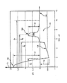
図2を参照すると、コア半径(μm)に対するΔ%の屈折率分布プロットが示される。これは、本願明細書において記載されているDCファイバ20の第1の実施例であって、以下の表1の実施例1に対応している。特に、中央コアセグメント22は、約2.0のアルファ、1.83%の最大Δ1%、及び、約1.83ミクロンの外側半径R1のアルファ分布を有する。コアセグメントは、約1.83%の中央線上の相対屈折率パーセントを有するステップ屈折率領域を含み、α分布が開始する約0.2μmの半径まで及ぶ。隣接したモートセグメント24は、コアセグメント22に当接してこれを包囲して、最も内側の半径R1で外側半径R2よりも僅かに負であるΔ2%を有するような、わずかなテーパーを有する屈折率分布である。モートセグメント24は、約5.97μmの外側半径R2及び約−0.5%の最も負のΔ2%を有する。実施例1では、半径R3に位置するリングセグメントを含む。この半径R3は、上記した如く、リングセグメントの中間位置半径である。R3は、リングセグメント26の半値高さ幅の中央位置まで計測される。リングセグメント26は、モートセグメント24に当接してこれを包囲し、7.70μmの半径R3、約0.9μmのリングセグメント26の半値高さ幅及び約0.8%のΔ2%を含む。リングセグメント26は、リングセグメント26のボディ29からR2でモートセグメント24の端部方向へ伸びる第1のテーパー部分25を含む。第2のテーパ化部分31は、ボディ29からR4のクラッド30の開始位置まで伸びる。
【実施例1】
【0037】
DCファイバ20は、図2に従ってモデル化され、上記した構成を有する。連続的にセグメントを数えて、中心線を包囲する中央コアセグメントである1で始まって、上記した定義に従って、コア構造が表1に記載されている。
【0038】
図6乃至8に図示したように、DCファイバ20の実施例は、以下の予測された特性を有する:
・ 1570nmでの全分散が−90ps/nm-km
・ 1595nmでの全分散が−115ps/nm-km
・ 1620nmでの全分散が−148ps/nm-km
・ 1595nmでの分散スロープが−1.18ps/nm2-km
・ 2019nmのカットオフ波長λc (まっすぐなDCファイバのLP01よりもより高次のLP11及びLP02の最も高いカットオフ波長)
・ 17.49μm2の実効面積(Aeff)
・ 0.5dB/kmの1595nmでの減衰
・ 6.4dBのピン配列曲げ損失
【実施例2】
【0039】
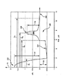
第2の3つのセグメントコアDCファイバ120は、図3に示される屈折率分布に従ってモデル化された。この場合、コアセグメント122のα分布は、中央線から0.2μmの位置で始まって、2.0のα、1.83%のΔ1%及び1.81μmのR1を有する。モートセグメント124は、テーパ化ステップ分布を有し、−0.6%の負のΔ2%及び5.38μmの外側半径R2を有する。リングセグメント126は、0.85%のΔ3%、7.02μmの上記した定義による中心位置半径R3及び0.8μmの中心位置幅を有する。追加の特性及び特徴は、表1に見いだされる。
【0040】
図6乃至図8に示すように、このDCファイバ120は、以下の予測された特性を有する:
・ 1570nmでの全分散が−118ps/nm-km
・ 1595nmでの全分散が−142ps/nm-km
・ 1620nmでの全分散が−180ps/nm-km
・ 1595nmでの分散スロープが−1.46ps/nm2-km
・ 1975nmのカットオフ波長λc (まっすぐなDCファイバのLP01よりもより高次のLP11及びLP02の最も高いもののカットオフ波長)
・ 17.49μm2の実効面積Aeff
・ 0.6dB/kmの1595nmでの減衰
・ 6.8dBのピン配列曲げ損失
この実施例において、優れたが得られるとともに、曲げ損失は実施例1の設計よりも改善される。
【実施例3】
【0041】
図4に示された分布を有する本発明によるDCファイバ220がモデル化された。コアセグメント222は、1.73%の相対屈折率Δ1及び1.83μmの外側半径R1を有する。α分布は、2.2のαを有する。モートセグメント224は、−0.5%のΔ2%及び5.87μmの外側セグメント半径R2を有する。リングセグメント226は、0.85のΔ3%及び7.53umの中心点半径R3を有する。このDCファイバ220は、以下の予測された特性を有した。
・ 1570nmでの全分散が−75ps/nm-km
・ 1595nmでの全分散が−95ps/nm-km
・ 1595nmでの全分散が−126ps/nm-km
・ 分散スロープが−1.04ps/nm2-km、
・ 2010nmのカットオフ波長λc (まっすぐなDCファイバのLP01よりもより高次のLP11及びLP02のうち最も高いもののカットオフ波長)
・ 16.73μm2の実効面積Aeff
・ 0.5dB/kmの1595nmでの減衰
・ 5.5dBのピン配列曲げ損失
【実施例4】
【0042】
3つのセグメント設計の更なる実施例として、本発明によるDCファイバ320がまたモデル化された。図5を参照すると、コアセグメント322は、2.0のα、1.83%のΔ1%、1.79μmのR1のα分布を有する。モートセグメント324は、−0.7%のΔ2%、5.33μmの外側半径R2を有する。リングセグメント326は0.85のΔ3%、中心点半径R3は6.93μm、リングセグメントの半値高さ幅は0.8μmである。
【0043】
本発明によるDCファイバは、以下の予測された特性を有する:
・ 1570nmでの全分散が−165ps/nm-km
・ 1595nmでの全分散が−222ps/nm-km
・ 1620nmでの全分散が−275ps/nm-km
・ 1595nmでの分散スロープが−2.40ps/nm2-km
・ 1950nmのカットオフ波長λc (まっすぐなDCファイバのLP01よりもより高次のLP11及びLP02のうちの最も高いもののカットオフ波長)
・ 19.84μm2の実効面積Aeff
・ 0.8dB/kmの1595nmでの減衰
・ 22dBのピン配列曲げ損失
【実施例5】
【0044】
3つのセグメント設計の更なる実施例として、本発明によるDCファイバ42が再度、モデル化された。図11を参照すると、コアセグメント422は2.0のα、1.89%のΔ1%及び1.86μmのR1のα分布を有する。モートセグメント424は、−0.61%のΔ2%、5.68μmの外側半径R2を有する。リングセグメント426は0.81のΔ3%を有し、中央半径R3は7.41μmであって、リングセグメントの半値高さ幅は0.9μmである。
【0045】
本発明によるDCファイバは、以下の予測された特性を有する。
・ 1570nmでの全分散が−58ps/nm-km
・ 1595nmでの全分散が−74ps/nm-km
・ 1620nmでの全分散が−95ps/nm-km
・ 1595nmでの分散スロープが−0.71ps/nm2-km
・ 2037nmのカットオフ波長λc (まっすぐなDCファイバのLP01よりもより高次のLP11及びLP02のうちの最も高いもののカットオフ波長)
・ 15.63μm2の実効面積Aeff
・ 3.0dBのピン配列曲げ損失、である。
【0046】
所望の特性を結果として達成する本発明による好適なDCファイバのパラメータを表1に示す。上記した3つのセグメント設計でのパラメータが表1に示される。各特定のセグメントの最大Δ%が半径R1に対応して記載される。半径がセグメントの中心点で計測される場合は、表に中にその旨を表記している。他の全ての半径は、セグメントの最も外側の半径であって、次の隣接したセグメントの最も内側の半径と一致する。ここで、セグメントは1(中央コアセグメントに対応する)から始まって外側に向かって計数される。これらの他の半径は、分布がクラッド屈折率と交差する位まで計測される。
【0047】
【表1】
本発明のDCファイバは、例えばOVD、MCVD若しくはPCVDの如き、公知の化学蒸着法によって製造され得る。好ましくは、DCファイバは、OVD法によって製造されることができて、コアは、所望の直径までアルミナマンドレル上にゲルマニア酸化物を添加され、且つ、コアセグメントの所望の屈折率分布を達成するために適量のゲルマニアを添加したシリコン酸化物を堆積することによって製造される。マンドレルが除去されて、コアセグメントを構成しているスートプリフォームが塩素含有雰囲気内で完全に乾燥させられた後に、ヘリウム雰囲気を含む圧密化炉で圧密化される。圧密化コアブランクは、目標とする堆積表面にモートセグメントスートを与えたコアケーンに再度、線引きされる。シリカスートは、モートの適当な直径まで堆積して、圧密化炉の塩素含有雰囲気によって乾燥する。スートプリフォームは、例えば、CF4又はSiF4の如き、フッ素含有雰囲気ガスによって添加され、その後圧密化されて、再度、ケーンに再線引きされる。これらのケーンは、リングセグメントスートを堆積するための堆積前処理表面となる。ゲルマニア添加シリカスートは、2つのセグメントケーン上に与えられ、その後に乾燥、圧密化処理される。再度、圧密化されたブランクが再線引きされ、ここにおいてセグメントコアの3つの全てのセグメントを含む最終的なコアケーンになるのである。続いて、クラッドを含む追加のシリカスートがらコアケーン上に与えられる。最終的なスートブランクが乾燥、圧密化された後にDCファイバが線引きされる線引き炉に移される。
【0049】
DCファイバの特定の実施例が開示されて、本願明細書において記載されてきたが、さまざまな変更態様及びバリエーションが本発明の範囲内から逸脱することなく本発明に対してなされ得ることは、当業者にとって明らかであろう。このように、添付の請求の範囲及びそれらの均等物の範囲内で与えられる本発明のこのような変更態様及びバリエーションをカバーすることを意図される。
【図面の簡単な説明】
【0050】
【図1】本発明によるDCファイバの各セグメントの断面斜視図である。
【図2】本発明によるDCファイバの第1の実施例のコア半径(μm)に対するΔ%のグラフである。
【図3】本発明によるDCファイバの第2の実施例のコア半径(μm)に対するΔ%のグラフである。
【図4】本発明によるDCファイバの第3の実施例のコア半径(μm)に対するΔ%のグラフである。
【図5】本発明によるDCファイバの第4の実施例のコア半径(μm)に対するΔ%のグラフである。
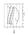
【図6】本発明によるDCファイバの幾つかの実施例の波長に対する分散のプロット図である。
【図7】本発明によるDCファイバの幾つかの実施例の波長に対する分散スロープのプロット図である。
【図8】本発明によるDCファイバの幾つかの実施例の波長に対するカッパ値のプロット図である。
【図9】本発明によるDCファイバを含む伝送システムの第1の実施例のダイアグラム図である。
【図10】本発明によるDCファイバを含む伝送システムの第2の実施例のダイアグラム図である。
【図11】本発明によるDCファイバの第5の実施例のコア半径(μm)に対するΔ%の図である。【Technical field】
[0001]
This application claims the priority and benefit of US patent application Ser. No. 09 / 965,406, filed Sep. 26, 2001.
[0002]
The present invention relates to a dispersion-compensating optical fiber and a transmission system including the same, and more specifically, a dispersion-compensating optical fiber and a transmission system having negative dispersion and a negative dispersion slope in an L band (1570 nm to 1620 nm) range. About.
[Background]
[0003]
In the communications industry, higher data signal rates are needed. Therefore, a search for a high-performance optical fiber designed to be communicable at a high bit rate over a long distance has been strongly desired. However, these high data signal rates have penalties associated therewith. In particular, dispersion is an important issue in a system using a fiber having a large effective area. Furthermore, positive dispersion occurs as a function of the length of the high data signal rate transmission fiber. Dispersion compensation (DC) fibers included in cables or dispersion compensation modules (DCM) have been designed to compensate for such dispersion. These DC fibers are short in length and generally have a negative dispersion slope and a negative dispersion to compensate for the positive dispersion and positive dispersion slope of the longer transmission portion. A suitable example of a DC fiber is US patent application Ser. No. 09 / 802,696, filed Mar. 9, 2001 by the same applicant as the present applicant. The bending and dispersion characteristics (dispersion and / or dispersion slope) of DC fibers in the L-band operating range between 1570 nm and 1620 nm are particularly important. This is particularly important for DC fibers wound on a DCM winding spool.
[0004]
In view of the above, DC fibers are required to:
(1) Included in DCM and single mode within the L-band wavelength range (1570 nm to 1620 nm)
(2) Maintain normal high performance optical fiber characteristics such as high strength, low attenuation and acceptable bending loss.
(3) Particularly effectively compensating for dispersion of non-zero dispersion shifted fiber (NZDSF) in the L band.
(Definition)
The following definitions are common usages in the prior art.
The refractive index profile is the relationship between the refractive index and the optical fiber radius.
The segment core has at least first and second segments, for example a central core and a mote; Each core segment has a refractive index profile and a maximum and minimum refractive index, respectively.
The radius of the segment of the core is defined with respect to the start and end of the segment of the refractive index profile or in the case of a ring segment with respect to the central position of the segment. FIG. 2 illustrates the definition of radius as used herein. The same definition is used in FIGS. Radius R of
-Effective area is defined as follows:
[0005]
[Expression 1]
Here, the integration range is 0 to ∞, and E is the electric field related to the propagation light measured at 1595 nm.
-Effective radius (Deff) Is defined as follows.
[0007]
[Expression 2]
-The distribution volume is defined as follows:
[0009]
[Equation 3]
Here, the distribution volume of the
Δ% is expressed as a relative measurement of the refractive index defined by the following equation:
[0011]
[Expression 4]
Where n unless otherwise statediIs the maximum refractive index of each region i (eg, 22, 24, 26) and ncIs the refractive index of the cladding (eg, 30) unless otherwise specified.
The alpha distribution is expressed as Δ (b)% with respect to the refractive index distribution; Here, b is a radius and is according to the following equation.
[0013]
[Equation 5]
Where b0Is the maximum position of the distribution, b1Is the position where Δ (b)% is zero, b is bi≦ b ≦ bfIt is. Here, Δ% is defined as described above. biIs the start of the α distribution and bfIs the end point of the α distribution, and α is a real number. The start and end positions of the α distribution are selected and input to the computer model. As used herein, when the α distribution follows the step refractive index distribution, the starting position of the α distribution is the intersection of the α distribution and the step distribution. In order to smoothly connect the distribution of adjacent distribution segments and the α distribution in modeling, the above-described equation is rewritten as follows.
[0015]
[Formula 6]
Where b0Is the first position of an adjacent segment.
-A pin array bend test is used to compare the relative resistance of optical fibers to bending. To perform this test, the optical fiber is first placed so that no bending loss occurs and attenuation is measured. The same optical fiber is placed so as to sew between the pin arrays, and attenuation is again measured. The loss caused by bending is the difference between the two attenuations. The pin array is a set of ten cylindrical pins that are arranged in a row and maintained vertically fixed on a flat surface. The distance from the center of the pin to the center is 5 mm. The pin diameter is 0.67 mm. The optical fiber is passed through adjacent pins on opposite sides. During this test, the optical fiber is tensioned enough to place the waveguide along a portion of the outer periphery of the pin.
DISCLOSURE OF THE INVENTION
[0017]
The DC fiber according to the invention disclosed and described herein is particularly suitable for compensating the dispersion and dispersion slope of a specific NZDSF in the L band.
[0018]
According to one embodiment of the present invention, the DC fiber has a segment core consisting of at least three segments, each segment being characterized by a refractive index profile, a relative refractive index Δ% and a radius size. . The overall refractive index profile of the DC fiber is suitable for the designed transmission system to operate in an L-band wavelength window with an intermediate point at about 1595 nm and a wavelength band between about 1570 nm and 1620 nm. ) Selected to provide a specific set of. The DC fiber according to the invention is suitable for compensation of NZDSF dispersion and / or dispersion slope accumulation. That is, such a DC fiber is designed to be connected to the NZDSF forming the transmission system, preferably to compensate for the dispersion and / or dispersion slope (most preferably both) of the NZDSF in the L band. Transmission systems that include DC fibers can preferably also include optical amplifiers, elements for wavelength division multiplexing, and elements used in other conventional systems. Preferably, the DC fiber is wound on a spool and accommodated in the module.
[0019]
According to an embodiment of the present invention, the total dispersion of a transmission system using a 100 km NZDSF transmission fiber (herein defined as measurable dispersion−total dispersion = total dispersion + waveguide dispersion + distributed dispersion) ) And the appropriate length of the DC fiber according to the present invention, a system of less than +/− 25 ps / nm can be constructed throughout the L band (between 1570 nm and 1620 nm). The fiber distribution designed according to the present invention exhibits excellent attenuation of less than 0.8 dB / km at 1595 nm. Furthermore, the bending loss as measured by the pin array test is preferably less than 25 dB, more preferably less than 10 dB, and most preferably less than 3 dB. That is, the DC fiber according to the present invention exhibits excellent bending loss and is therefore advantageously used even when wound on a small diameter DCM utilized in transmission systems that compensate for NZDSF dispersion and dispersion slope. It can be done.
[0020]
According to a preferred embodiment of the DC fiber, each of the core segments is characterized by a refractive index profile, and preferably at least one of the segments has an α profile. Most preferably, the core distribution is positive Δ1% Central core segment, negative Δ2% Moat region and positive ΔThree% Ring segments included. Preferably, the ring segment has a non-step refractive index profile and is offset from the moat segment.
[0021]
The DC fiber according to the present invention has a segment core with at least three segments, and the refractive index profile of the segment core is 1595 nm, more preferably negative total dispersion and negative over the entire L band from 1570 nm to 1620 nm. Is chosen to give a distributed slope. The DC fiber of the present invention has a total dispersion at 1595 nm between about -70 ps / nm-km and -225 ps / nm-km and a dispersion slope of -0.7 ps / nm at 1595 nm.2It is more negative than -km. More preferably, the dispersion at 1595 nm is between about -95 and -225 ps / nm-km, and the dispersion slope is -0.9 ps / nm at 1595 nm.2It is more negative than -km. More preferably, the dispersion at 1595 nm is between about -110 and -150 ps / nm-km, more preferably -80 to -190 ps / nm- over the L-band wavelength range of 1570 nm to 1620 nm. km. Most preferably, the dispersion slope is -0.70 ps / nm at 1595 nm.2More negative than -km, more preferably -0.9 ps / nm at 1595 nm2-km and -1.5ps / nm2between -km.
[0022]
Preferably, the DC fiber is -0.5 ps / nm over the entire L band from 1570 nm to 1620 nm.2more negative than -km, more preferably more negative than -0.7, most preferably -1.2 ps / nm2Less than -km. Preferably, the dispersion slope is -0.5 and -2.5 ps / nm over the entire L band.2-km and more preferably -1.0 and -1.8 ps / nm.2between -km.
[0023]
The DC optical fiber has a value between 90 nm and 110 nm at a kappa value defined by dividing the total dispersion at 1595 nm by the dispersion slope at 1595 nm, more preferably the kappa value is between 90 nm and 105 nm. Most preferably, it is between 95 nm and 100 nm. Most preferably, the kappa value is between 80 nm and 155 nm over the L band range of 1570 nm to 1620 nm, more preferably between 85 nm and 110 nm.
[0024]
The DC fiber includes a central core segment having an α distribution in the range of about 1.8 to 5.0, more preferably about 2.0 to 2.2.
[0025]
DC fibers according to embodiments of the present invention have a positive Δ greater than 1.5%.1A central core segment with a negative Δ, which is adjacent to the central core segment and less than -0.3%2A mote segment with a% and a positive Δ that is adjacent to the mote segment and greater than 0.6%ThreeAnd a ring segment having a percentage.
[0026]
More preferably, the DC fiber according to an embodiment of the present invention has a positive Δ greater than 1.7%.1A central core segment having a%, a mote segment adjacent to the central core segment and having a negative Δ2% less than -0.5%, and adjacent to the moat segment and greater than 0.8% Positive ΔThreeAnd a ring segment having a percentage.
[0027]
The effective area of the DC fiber according to the present invention at 1595 nm is 15 μm.2Larger, more preferably 17 μm2Is bigger than.
[0028]
According to another embodiment of the present invention, an optical transmission system is provided having a dispersion compensating optical fiber. Here, the dispersion compensating fiber has at least three segments, and its refractive index profile has a total dispersion between about -70 ps / nm-km to -225 ps / nm-km at 1550 nm and -0.7 ps at 1595 nm. / Nm2Includes segment cores selected to give a negative dispersion slope less than -km.
[0029]
Additional features and advantages of the invention will be set forth in the detailed description of the invention which follows, and will be readily apparent to those skilled in the art from the description of the detailed description of the invention. Will be recognized by practicing the invention described herein including the detailed description of the invention. The foregoing general description and the following detailed description are merely exemplary of the invention and provide an overview or framework for understanding the features and characteristics of the invention as claimed by the claims. It should be understood that it is only intended to do. The accompanying drawings are included to provide a further understanding of the invention, and are incorporated in and constitute a part of this specification. The drawings illustrate certain embodiments of the invention and, together with the description of the invention, provide a description of the principles and operation of the invention.
BEST MODE FOR CARRYING OUT THE INVENTION
[0030]
The DC fiber according to the present invention is implemented in a series of segmented core designs that yield a specific set of characteristics (characteristic values) desired, and is fully described herein. The family of DC fiber core designs includes, but is not limited to, the specific examples described herein. That is, it should be appreciated that modifications to the specific embodiments described herein can be made within the scope of the present invention. A first embodiment is described in FIGS. The
[0031]
Each
[0032]
As described above, by adding such a dopant, a DC fiber core having a precisely defined distribution can be obtained. In particular, with the addition of an appropriate amount of dopant, the
[0033]
In particular, as shown in FIG. 6, the DC fiber family preferably has a total dispersion that varies between about −60 ps / nm-km and −275 ps / nm-km over the L-band operating window. In one example, the total dispersion varies between −80 and −190 ps / nm-km, as shown by
[0034]
Without being limited thereto, according to one embodiment, the transmission system 32 of FIG. 9 including a 100 km length of
[0035]
Table 1 shows a dispersion of about 7.9 ps / nm-km at 1595 nm and 0.079 ps / nm.2We define a family of DC fibers of the present invention that have the desired characteristics for compensating the dispersion slope and dispersion of NZDSF with a dispersion slope of -km. It will be appreciated that in the following examples, the attenuation is very small and the bending induced loss is within an acceptable range.
[0036]
Referring to FIG. 2, a refractive index profile plot of Δ% against core radius (μm) is shown. This is a first example of the
[Example 1]
[0037]
The
[0038]
As illustrated in FIGS. 6-8, an embodiment of the
-Total dispersion at 1570nm is -90ps / nm-km
-The total dispersion at 1595nm is -115ps / nm-km
-Total dispersion at 1620nm is -148ps / nm-km
・ Dispersion slope at -1595nm is -1.18ps / nm2-km
・ Cutoff wavelength λ of 2019 nmc(Straight DC fiber LP01Higher order LP than11And LP02The highest cutoff wavelength)
・ 17.49μm2Effective area (Aeff)
Attenuation at 1595 nm of 0.5 dB / km
6.4 dB pin array bending loss
[Example 2]
[0039]
The second three segment
[0040]
As shown in FIGS. 6-8, the
-Total dispersion at 1570 nm is -118 ps / nm-km
-Total dispersion at 1595nm is -142ps / nm-km
-Total dispersion at 1620nm is -180ps / nm-km
・ Dispersion slope at -1595nm is -1.46ps / nm2-km
1975 nm cutoff wavelength λc(Straight DC fiber LP01Higher order LP than11And LP02Cutoff wavelength of the highest)
・ 17.49μm2Effective area Aeff
Attenuation at 1595 nm of 0.6 dB / km
6.8dB pin array bending loss
In this example, excellent results are obtained and the bending loss is improved over the design of Example 1.
[Example 3]
[0041]
A
-Total dispersion at 1570 nm is -75 ps / nm-km
-Total dispersion at 1595nm is -95ps / nm-km
-Total dispersion at 1595nm is -126ps / nm-km
・ Dispersion slope is -1.04ps / nm2-km,
・ Cutoff wavelength λ of 2010 nmc(Straight DC fiber LP01Higher order LP than11And LP02(The cut-off wavelength of the highest one)
・ 16.73μm2Effective area Aeff
Attenuation at 1595 nm of 0.5 dB / km
・ 5.5dB pin array bending loss
[Example 4]
[0042]
As a further example of a three segment design, a
[0043]
The DC fiber according to the present invention has the following expected properties:
Total dispersion at 1570 nm is -165 ps / nm-km
Total dispersion at 1595 nm is -222 ps / nm-km
-Total dispersion at 1620 nm is -275 ps / nm-km
-Dispersion slope at -1955 nm is -2.40 ps / nm2-km
1950 nm cut-off wavelength λc(Straight DC fiber LP01Higher order LP than11And LP02(The cut-off wavelength of the highest one)
・ 19.84μm2Effective area Aeff
Attenuation at 0.85 dB / km at 1595 nm
・ 22dB pin array bending loss
[Example 5]
[0044]
As a further example of a three segment design, the
[0045]
The DC fiber according to the present invention has the following predicted characteristics.
-Total dispersion at 1570nm is -58ps / nm-km
-Total dispersion at 1595nm is -74ps / nm-km
-Total dispersion at 1620 nm is -95 ps / nm-km
・ Dispersion slope at 1595nm is -0.71ps / nm2-km
・ Cutoff wavelength λ of 2037 nmc(Higher order LP than the straight DC fiber LP0111And LP02(The cut-off wavelength of the highest one)
・ 15.63μm2Effective area Aeff
-3.0 dB pin array bend loss.
[0046]
Table 1 shows the parameters of a preferred DC fiber according to the present invention that achieves the desired properties as a result. The parameters for the three segment designs described above are shown in Table 1. The maximum Δ% of each specific segment is the radius R1It is described corresponding to. If the radius is measured at the center point of the segment, this is shown in the table. All other radii are the outermost radius of the segment and coincide with the innermost radius of the next adjacent segment. Here, the segments are counted outwards starting from 1 (corresponding to the central core segment). These other radii are measured to the extent that the distribution intersects the cladding refractive index.
[0047]
[Table 1]
The DC fiber of the present invention can be manufactured by a known chemical vapor deposition method such as OVD, MCVD or PCVD. Preferably, the DC fiber can be manufactured by the OVD method, the core is doped with germania oxide on the alumina mandrel to the desired diameter, and to achieve the desired refractive index profile of the core segment. It is manufactured by depositing a silicon oxide to which an appropriate amount of germania is added. After the mandrel is removed and the soot preform constituting the core segment is completely dried in a chlorine-containing atmosphere, the mandrel is consolidated in a consolidation furnace containing a helium atmosphere. The consolidated core blank is again drawn to a core cane that has been mote segmented soot on the target deposition surface. Silica soot is deposited to the appropriate moat diameter and dried by the chlorine-containing atmosphere of the consolidation furnace. The soot preform is, for example, CFFourOr SiFFourAs described above, it is added by a fluorine-containing atmospheric gas, and then it is consolidated and redrawn again in the cane. These canes provide a pre-deposition surface for depositing ring segment soot. The germania-added silica soot is applied over two segment canes and then dried and consolidated. Again, the consolidated blank is redrawn, where it becomes the final core cane containing all three segments of the segment core. Subsequently, additional silica soot containing the cladding is applied over the core cane. After the final soot blank is dried and consolidated, it is transferred to a drawing furnace where the DC fiber is drawn.
[0049]
While specific embodiments of DC fibers have been disclosed and described herein, it should be understood that various modifications and variations can be made to the present invention without departing from the scope of the invention. It will be clear to the contractor. Thus, it is intended to cover such modifications and variations of this invention that are given within the scope of the appended claims and their equivalents.
[Brief description of the drawings]
[0050]
FIG. 1 is a cross-sectional perspective view of each segment of a DC fiber according to the present invention.
FIG. 2 is a graph of Δ% against core radius (μm) of the first embodiment of the DC fiber according to the present invention.
FIG. 3 is a graph of Δ% versus core radius (μm) of a second embodiment of a DC fiber according to the present invention.
FIG. 4 is a graph of Δ% against core radius (μm) of a third embodiment of a DC fiber according to the present invention.
FIG. 5 is a graph of Δ% versus core radius (μm) of a fourth embodiment of a DC fiber according to the present invention.
FIG. 6 is a plot of dispersion versus wavelength for some embodiments of DC fiber according to the present invention.
FIG. 7 is a plot of dispersion slope versus wavelength for some embodiments of DC fiber according to the present invention.
FIG. 8 is a plot of kappa value versus wavelength for some embodiments of DC fiber according to the present invention.
FIG. 9 is a diagram of a first embodiment of a transmission system including a DC fiber according to the present invention.
FIG. 10 is a diagram of a second embodiment of a transmission system including a DC fiber according to the present invention.
FIG. 11 is a graph of Δ% with respect to the core radius (μm) of the fifth embodiment of the DC fiber according to the present invention.
Claims (26)
前記中央コアセグメントに隣接し、−0.4%よりも負のΔ2%を有するモートセグメントと、
前記モートセグメントに隣接し、0.7%よりも大なる正のΔ3%を有するリングセグメントと、を更に含むことを特徴とする請求項5記載の分散補償光ファイバ。A central core segment having a positive Δ 1 % greater than 1.5%;
Adjacent the central core segment, a moat segment having a 2% negative Δ than -0.4%,
6. The dispersion compensating optical fiber of claim 5, further comprising a ring segment adjacent to the moat segment and having a positive [Delta] 3 % greater than 0.7%.
約−0.3%から−0.9%までの範囲内にあるΔ2%及び約4.5μmから6.5μmまでの範囲内にある半径R2を有するモートセグメントと、
約0.6%から1.1%までの範囲内にあるΔ3%及び約6.0μmから8.0μmまでの範囲内にある中央半径R3を有するリングセグメントと、を更に含むことを特徴とする請求項1記載の分散補償光ファイバ。A central core segment having Δ 1 % in the range of about 1.5% to 2.0% and a radius R 1 in the range of about 1.5 μm to 2.0 μm;
A mote segment having a Δ 2 % in the range of about −0.3% to −0.9% and a radius R 2 in the range of about 4.5 μm to 6.5 μm;
A ring segment having a Δ 3 % in the range of about 0.6% to 1.1% and a central radius R 3 in the range of about 6.0 μm to 8.0 μm. The dispersion compensating optical fiber according to claim 1.
前記中央コアセグメントに隣接し、−0.5%よりも負のΔ2%を有するモートセグメントと、
前記モートセグメントに隣接し、約0.8%よりも正のΔ3%を有するリングセグメントと、を更に含むことを特徴とする請求項1記載の分散補償光ファイバ。A central core segment having a positive Δ 1 % greater than 1.7%;
Adjacent the central core segment, a moat segment having a 2% negative Δ than -0.5%,
The dispersion compensating optical fiber of claim 1, further comprising a ring segment adjacent to the moat segment and having a Δ 3 % more positive than about 0.8%.
約−0.5%から−0.7%までの範囲内にあるΔ2%及び約5.0μmから6.0μmまでの範囲内にある半径R2を有するモートセグメントと、
約0.75%から0.9%までの範囲内にあるΔ3%及び約6.5μmから8.0μmまでの範囲内にある半径R3を有するリングセグメントとを更に含むことを特徴とする請求項1記載の分散補償光ファイバ。A central core segment having a Δ 1 % in the range of about 1.7% to 1.9% and a radius R 1 in the range of about 1.7 μm to 1.9 μm;
A mote segment having a Δ 2 % in the range of about −0.5% to −0.7% and a radius R 2 in the range of about 5.0 μm to 6.0 μm;
And a ring segment having a Δ 3 % in the range of about 0.75% to 0.9% and a radius R 3 in the range of about 6.5 μm to 8.0 μm. The dispersion compensating optical fiber according to claim 1.
約4.5μmと6.5μmの間の範囲内にある外側半径R2を有するモートセグメントと、
約6.0μmと8.0μmの間の範囲内にある中央半径R3を有するリングセグメントと、を更に含むことを特徴とする請求項1記載の分散補償光ファイバ。A central core segment having an outer radius R 1 in the range between about 1.5 μm and 2.0 μm;
A mote segment having an outer radius R 2 in a range between about 4.5 μm and 6.5 μm;
The dispersion-compensating optical fiber of claim 1, further comprising a ring segment having a central radius R 3 in a range between about 6.0 μm and 8.0 μm.
Applications Claiming Priority (2)
| Application Number | Priority Date | Filing Date | Title |
|---|---|---|---|
| US09/965,406 US20030059186A1 (en) | 2001-09-26 | 2001-09-26 | L-band dispersion compensating fiber and transmission system including same |
| PCT/US2002/028911 WO2003027737A1 (en) | 2001-09-26 | 2002-09-09 | L-band dispersion compensating fiber and transmission system including same |
Publications (2)
| Publication Number | Publication Date |
|---|---|
| JP2005504334A true JP2005504334A (en) | 2005-02-10 |
| JP2005504334A5 JP2005504334A5 (en) | 2005-12-22 |
Family
ID=25509930
Family Applications (1)
| Application Number | Title | Priority Date | Filing Date |
|---|---|---|---|
| JP2003531228A Pending JP2005504334A (en) | 2001-09-26 | 2002-09-09 | L-band dispersion compensating fiber and transmission system including the same |
Country Status (6)
| Country | Link |
|---|---|
| US (2) | US20030059186A1 (en) |
| EP (1) | EP1430337A1 (en) |
| JP (1) | JP2005504334A (en) |
| KR (1) | KR20040037130A (en) |
| CN (1) | CN1646957A (en) |
| WO (1) | WO2003027737A1 (en) |
Families Citing this family (15)
| Publication number | Priority date | Publication date | Assignee | Title |
|---|---|---|---|---|
| US6711332B2 (en) * | 2001-11-05 | 2004-03-23 | Corning Incorporated | Highly negative-slope dispersion compensating fiber and transmission system including same |
| US6650814B2 (en) | 2001-12-11 | 2003-11-18 | Corning Incorporated | Single mode dispersion compensating optical fiber |
| US6751390B2 (en) * | 2001-12-11 | 2004-06-15 | Corning Incorporation | Dispersion and dispersion slope compensating fiber and optical transmission system utilizing same |
| JP2003241000A (en) * | 2002-02-19 | 2003-08-27 | Furukawa Electric Co Ltd:The | Optical fiber, and optical amplifier and optical transmission system using the optical fiber |
| US6757468B2 (en) * | 2002-03-14 | 2004-06-29 | Corning Incorporated | Dispersion compensation optical fiber and optical transmission line using same |
| US7102812B2 (en) * | 2002-10-15 | 2006-09-05 | Corning Incorporated | Devices and methods for raman amplification and dispersion compensation |
| US6888993B2 (en) * | 2002-11-27 | 2005-05-03 | Corning Incorporated | Dispersion compensating optical fiber for SMF and transmission link including same |
| US6993228B2 (en) | 2003-08-13 | 2006-01-31 | Corning Incorporated | Dispersion compensated optical fiber transmission system and module including micro-structured optical fiber |
| CN1300609C (en) * | 2003-10-28 | 2007-02-14 | 长飞光纤光缆有限公司 | High performance chromatic dispersion compensation optical fiber and its producing method |
| US6985662B2 (en) * | 2003-10-30 | 2006-01-10 | Corning Incorporated | Dispersion compensating fiber for moderate dispersion NZDSF and transmission system utilizing same |
| CN100406933C (en) * | 2003-12-24 | 2008-07-30 | 古河电气工业株式会社 | Optical fiber, optical module and Raman amplifier using the same |
| US7046433B2 (en) * | 2003-12-30 | 2006-05-16 | The Furukawa Electric Co., Ltd. | Optical fiber, and optical module and Raman amplifier using the optical fiber |
| US20050185905A1 (en) * | 2004-02-20 | 2005-08-25 | Burke James P. | Dispersion correction fiber, transmission system and method of operating same |
| JP2007005484A (en) * | 2005-06-22 | 2007-01-11 | Fujitsu Ltd | Optical amplifier and optical fiber |
| US7689083B1 (en) * | 2006-11-28 | 2010-03-30 | Corning Incorporated | High SBS threshold optical fiber |
Family Cites Families (27)
| Publication number | Priority date | Publication date | Assignee | Title |
|---|---|---|---|---|
| US4715679A (en) | 1981-12-07 | 1987-12-29 | Corning Glass Works | Low dispersion, low-loss single-mode optical waveguide |
| US5361319A (en) | 1992-02-04 | 1994-11-01 | Corning Incorporated | Dispersion compensating devices and systems |
| US5448674A (en) | 1992-11-18 | 1995-09-05 | At&T Corp. | Article comprising a dispersion-compensating optical waveguide |
| JPH07261048A (en) | 1994-03-23 | 1995-10-13 | Sumitomo Electric Ind Ltd | Dispersion compensating fiber |
| CA2170815C (en) | 1995-03-10 | 2002-05-28 | Youichi Akasaka | Dispersion compensating optical fiber |
| DE69630426T2 (en) | 1995-08-31 | 2004-08-19 | Sumitomo Electric Industries, Ltd. | Dispersion-compensating fiber and process for its manufacture |
| GB9526183D0 (en) | 1995-12-21 | 1996-02-21 | Stc Submarine Systems Ltd | Dispersion slope equalisaion for wdm systems wih branches |
| CA2202586C (en) | 1996-04-15 | 2003-05-06 | Masashi Onishi | Dispersion compensating fiber and optical transmission system including the same |
| US5999679A (en) | 1997-07-14 | 1999-12-07 | Corning Incorporated | Dispersion compensating single mode waveguide |
| JPH10253847A (en) | 1997-03-11 | 1998-09-25 | Furukawa Electric Co Ltd:The | Dispersion compensation optical fiber |
| CA2232101A1 (en) | 1997-03-25 | 1998-09-25 | Kazunori Mukasa | Dispersion compensating optical fiber, and wavelength division multiplex light transmission line using the same |
| AU731474B2 (en) | 1997-08-07 | 2001-03-29 | Corning Incorporated | Dispersion managed optical waveguide fiber |
| WO1999013366A1 (en) | 1997-09-10 | 1999-03-18 | The Furukawa Electric Co., Ltd. | Dispersion slope-compensated optical fiber |
| JP3337954B2 (en) | 1997-09-17 | 2002-10-28 | 株式会社フジクラ | Dispersion compensating optical fiber |
| EP1130428A4 (en) * | 1998-09-18 | 2005-08-31 | Sumitomo Electric Industries | Dispersion compensating fiber |
| FR2786343A1 (en) * | 1998-11-23 | 2000-05-26 | Cit Alcatel | DISPERSION COMPENSATION FIBER FOR WAVELENGTH MULTIPLEXED OPTICAL FIBER TRANSMISSION SYSTEM EMPLOYING OFFSET DISPERSED LINE FIBER |
| MXPA01011017A (en) * | 1999-04-30 | 2002-05-06 | Corning Inc | Dispersion compensating fiber. |
| WO2000070378A1 (en) | 1999-05-17 | 2000-11-23 | The Furukawa Electric Co., Ltd. | Optical fiber and optical transmission line comprising the optical fiber |
| FR2795828B1 (en) * | 1999-06-29 | 2001-10-05 | Cit Alcatel | OPTICAL FIBER FOR THE COMPENSATION OF THE CHROMATIC DISPERSION OF A POSITIVE CHROMATIC DISPERSION OPTICAL FIBER |
| KR20020012319A (en) * | 1999-07-19 | 2002-02-15 | 오카야마 노리오 | Dispersion compensation system |
| FR2799006B1 (en) * | 1999-09-02 | 2002-02-08 | Cit Alcatel | OPTICAL FIBER FOR ONLINE COMPENSATION OF THE CHROMATIC DISPERSION OF AN OPTICAL FIBER WITH POSITIVE CHROMATIC DISPERSION |
| JP2001311849A (en) | 2000-02-25 | 2001-11-09 | Furukawa Electric Co Ltd:The | Low dispersion optical fiber and optical transmission system using the same |
| EP1189082A4 (en) * | 2000-02-25 | 2005-01-12 | Furukawa Electric Co Ltd | Low-dispersion optical fiber and optical transmission system using the low-dispersion optical fiber |
| US6445864B2 (en) * | 2000-03-24 | 2002-09-03 | Corning Incorporated | Dispersion compensating optical fiber |
| US6477306B2 (en) * | 2000-04-11 | 2002-11-05 | Sumitomo Electric Industries, Ltd. | Dispersion-compensating optical fiber, and, optical transmission line and dispersion-compensating module respectively including the same |
| US6400877B1 (en) * | 2000-09-01 | 2002-06-04 | Sumitomo Electric Industries, Ltd. | Negative-dispersion optical fiber and optical transmission line incorporating the same |
| US6490398B2 (en) * | 2001-02-21 | 2002-12-03 | Fitel Usa Corp. | Dispersion-compensating fiber having a high figure of merit |
-
2001
- 2001-09-26 US US09/965,406 patent/US20030059186A1/en not_active Abandoned
-
2002
- 2002-09-09 CN CN02818485.8A patent/CN1646957A/en active Pending
- 2002-09-09 US US10/238,100 patent/US6807351B2/en not_active Expired - Fee Related
- 2002-09-09 EP EP02757692A patent/EP1430337A1/en not_active Withdrawn
- 2002-09-09 JP JP2003531228A patent/JP2005504334A/en active Pending
- 2002-09-09 KR KR10-2004-7004383A patent/KR20040037130A/en not_active Application Discontinuation
- 2002-09-09 WO PCT/US2002/028911 patent/WO2003027737A1/en not_active Application Discontinuation
Also Published As
| Publication number | Publication date |
|---|---|
| US20030063881A1 (en) | 2003-04-03 |
| US20030059186A1 (en) | 2003-03-27 |
| WO2003027737A1 (en) | 2003-04-03 |
| US6807351B2 (en) | 2004-10-19 |
| KR20040037130A (en) | 2004-05-04 |
| EP1430337A1 (en) | 2004-06-23 |
| CN1646957A (en) | 2005-07-27 |
Similar Documents
| Publication | Publication Date | Title |
|---|---|---|
| EP1353202A2 (en) | Optical fibre with optimised dispersion | |
| JP2005504334A (en) | L-band dispersion compensating fiber and transmission system including the same | |
| US6961500B2 (en) | Dispersion and slope compensating optical fiber and transmission link including same | |
| US6711332B2 (en) | Highly negative-slope dispersion compensating fiber and transmission system including same | |
| US6757468B2 (en) | Dispersion compensation optical fiber and optical transmission line using same | |
| US6650814B2 (en) | Single mode dispersion compensating optical fiber | |
| JP4533388B2 (en) | Dispersion compensating fiber for NZDSF having medium dispersion and transmission system using the same | |
| WO2006012107A2 (en) | Large kappa dispersion compensating fiber and transmission system | |
| JP2006508397A (en) | SMF dispersion compensating optical fiber and transmission link including the same | |
| JP4861181B2 (en) | High performance index dispersion compensating fiber for standard single mode fiber and transmission system using the dispersion compensating fiber | |
| JP2005533278A (en) | Dispersion compensating fiber for low dispersion inclined transmission fiber and optical transmission line using the same | |
| US20040076392A1 (en) | Low Kappa, dual-moat DC fiber and optical transmission line | |
| US20180011245A1 (en) | Dispersion shifted optical fiber | |
| JP2004093650A (en) | Optical transmission line and dispersion compensated optical fiber using therefor | |
| JP2004271644A (en) | Optical fiber and optical transmission system using the same |
Legal Events
| Date | Code | Title | Description |
|---|---|---|---|
| A621 | Written request for application examination |
Free format text: JAPANESE INTERMEDIATE CODE: A621 Effective date: 20050617 |
|
| A977 | Report on retrieval |
Free format text: JAPANESE INTERMEDIATE CODE: A971007 Effective date: 20080722 |
|
| A131 | Notification of reasons for refusal |
Free format text: JAPANESE INTERMEDIATE CODE: A131 Effective date: 20080729 |
|
| A02 | Decision of refusal |
Free format text: JAPANESE INTERMEDIATE CODE: A02 Effective date: 20090106 |