JP2005354136A - Communication terminal, connection management server and communication system - Google Patents
Communication terminal, connection management server and communication system Download PDFInfo
- Publication number
- JP2005354136A JP2005354136A JP2004169438A JP2004169438A JP2005354136A JP 2005354136 A JP2005354136 A JP 2005354136A JP 2004169438 A JP2004169438 A JP 2004169438A JP 2004169438 A JP2004169438 A JP 2004169438A JP 2005354136 A JP2005354136 A JP 2005354136A
- Authority
- JP
- Japan
- Prior art keywords
- communication
- terminal
- connection
- user
- communication terminal
- Prior art date
- Legal status (The legal status is an assumption and is not a legal conclusion. Google has not performed a legal analysis and makes no representation as to the accuracy of the status listed.)
- Pending
Links
Images


Landscapes
- Small-Scale Networks (AREA)
- Mobile Radio Communication Systems (AREA)
- Telephone Function (AREA)
- Telephonic Communication Services (AREA)
Abstract
Description
本発明は、移動通信技術に関し、とくに、移動通信端末が所定の通信ネットワークと接続するための設定処理に関する。 The present invention relates to mobile communication technology, and more particularly to a setting process for a mobile communication terminal to connect to a predetermined communication network.
ブロードバンドネットワークの整備に伴い、いわゆるユビキタス社会への移行が進みつつある。現代の情報機器の多くは、ネットワークを介して、情報交換することを前提として設計されている。パーソナルコンピュータはもとより、PDA(Personal Digital Assistance)などの携帯端末機器のアプリケーションソフトウェアにおいても、これらの機器が有する通信機能を利用するものは多い。
これらの通信機能を有する情報機器(以下、「情報通信端末」とよぶ)が、IEEE802.11などにより規格策定される無線LAN(Local Area Network)に接続するためには、さまざまな通信設定が必要である。たとえば、無線LANとの接続においては、ESSID(Extended Service Set Identifier)やWEP(Wired Equivalent Privacy)キー、IEEE 802.11i/WPA(Wi-Fi Protected Access)やIEEE 802.1xにおいて認証に利用される電子証明書もしくはPSK(Pre shared key)など、無線LANのセキュリティに関する各種情報を情報通信端末に設定する必要がある。また、無線LANに接続するための通信設定情報は恒常的なものではなく、システムの運用変更に応じて、その設定を適宜変更する必要がある。 Various communication settings are required for an information device (hereinafter referred to as an “information communication terminal”) having these communication functions to connect to a wireless local area network (LAN) defined by IEEE 802.11 or the like. It is. For example, in connection with a wireless LAN, it is used for authentication in ESSID (Extended Service Set Identifier), WEP (Wired Equivalent Privacy) key, IEEE 802.11i / WPA (Wi-Fi Protected Access), and IEEE 802.1x. Various information related to wireless LAN security such as an electronic certificate or PSK (Pre shared key) needs to be set in the information communication terminal. Further, the communication setting information for connecting to the wireless LAN is not constant, and it is necessary to change the setting as appropriate in accordance with the operation change of the system.
このように、情報通信端末を所定の通信ネットワークに接続させるために必要とされる設定入力の煩雑さは、通信システムの利便性を低下させる。また、家電製品がネットワーク接続機能を有する場合には、その設定のための入力インタフェースを設けること自体が困難となる場合もある。 Thus, the complexity of the setting input required for connecting the information communication terminal to a predetermined communication network reduces the convenience of the communication system. In addition, when the home appliance has a network connection function, it may be difficult to provide an input interface for the setting.
本発明は、このような課題に鑑みてなされたものであり、その主たる目的は、簡便なインタフェースにより、情報通信端末が通信ネットワークと接続するために必要な設定を行うための技術を提供することである。 The present invention has been made in view of such problems, and a main object thereof is to provide a technique for performing settings necessary for an information communication terminal to connect to a communication network with a simple interface. It is.
上記課題を解決するために、本発明のある態様の通信端末装置は、所定の構内通信網において当該端末装置を識別するために必要とされる情報である端末IDを記憶し、当該端末装置と構内通信網の接続を支援する接続支援装置に対し、近距離無線通信によって端末IDを送信する。この装置は、接続支援装置を介して端末IDを受信した接続管理サーバから、当該端末装置が構内通信網と接続するために必要とする通信設定情報を接続支援装置を介した近距離無線通信により受信し、その通信設定情報に基づいて構内通信網と接続する。 In order to solve the above problem, a communication terminal device according to an aspect of the present invention stores a terminal ID, which is information required to identify the terminal device in a predetermined local area communication network, The terminal ID is transmitted by short-range wireless communication to the connection support apparatus that supports the connection of the local communication network. This device receives communication setting information necessary for the terminal device to connect to the local communication network from the connection management server that has received the terminal ID via the connection support device by short-range wireless communication via the connection support device. Receive and connect to the local communication network based on the communication setting information.
この態様によると、通信端末装置は接続支援装置との近距離無線通信を介して、接続管理サーバとデータを送受信する。近距離無線通信とは、たとえば、RFID(Radio Frequency-Identification)カード、ブルートゥース(bluetooth:登録商標)やIrDA(Infrared Data Association)など、所定範囲内における電磁波や光を搬送波とする通信であってよい。なお、通信端末装置は、ピアツーピアの有線接続により、接続支援装置と接続してもよいし、直接接続管理サーバと接続してもよい。通信端末装置は、このような簡易な通信インタフェースにより、接続先として本来目的とする構内通信網に対する通信設定情報を取得できる。そのため、通信端末装置に通信設定情報を設定する上での大幅な省力化が可能となる。 According to this aspect, the communication terminal device transmits / receives data to / from the connection management server via short-range wireless communication with the connection support device. The short-range wireless communication may be communication using an electromagnetic wave or light within a predetermined range as a carrier wave, such as an RFID (Radio Frequency-Identification) card, Bluetooth (registered trademark), or IrDA (Infrared Data Association). . Note that the communication terminal device may be connected to the connection support device through a peer-to-peer wired connection, or may be connected to the direct connection management server. The communication terminal device can acquire communication setting information for the intended local area communication network as a connection destination through such a simple communication interface. Therefore, significant labor savings can be achieved in setting communication setting information in the communication terminal device.
本発明の別の態様は、接続管理サーバである。この接続管理サーバは、所定の構内通信網において通信端末装置を識別するために必要とされる情報である端末IDを、通信端末装置と構内通信網の接続を支援する接続支援装置を介して通信端末装置から受信し、通信端末装置が構内通信網に接続するために必要とする通信設定情報を生成して接続支援装置を介して通信端末装置に送信する。 Another aspect of the present invention is a connection management server. The connection management server communicates a terminal ID, which is information required to identify a communication terminal device in a predetermined local communication network, via a connection support device that supports connection between the communication terminal device and the local communication network. The communication setting information received from the terminal device and necessary for the communication terminal device to connect to the local communication network is generated and transmitted to the communication terminal device via the connection support device.
この態様によると、接続管理サーバは通信端末装置が通信ネットワークに接続するために必要な通信設定情報を生成する。また、その通信設定情報は、接続支援装置を介した近距離無線通信によって通信端末装置に送信される。そのため、通信端末装置のユーザにとっては、通信設定情報を自ら設定する手間が省かれるため、通信システムの利便性が向上する。 According to this aspect, the connection management server generates communication setting information necessary for the communication terminal device to connect to the communication network. The communication setting information is transmitted to the communication terminal device by short-range wireless communication via the connection support device. For this reason, the user of the communication terminal apparatus can save the trouble of setting the communication setting information by itself, thereby improving the convenience of the communication system.
本発明によれば、情報通信端末が通信ネットワークと接続するための設定を簡便化する上で効果がある。 According to the present invention, there is an effect in simplifying the setting for the information communication terminal to connect to the communication network.
図1は、本実施例における通信システム300のハードウェア構成図である。LAN106は、一般家庭などの屋内に設置される。LAN106はゲートウェイ104を介して、インターネット102と接続される。同図において実線は有線接続を表す。また、破線は無線接続を表す。
FIG. 1 is a hardware configuration diagram of a
LAN106には、アクセスポイント112a、アクセスポイント112b(以下、まとめていうときには、単に「アクセスポイント112」とよぶ)が接続される。各アクセスポイント112は、それぞれ所定のエリアを管理する。たとえば、アクセスポイント112aが管理するエリア140aは、リビングルームをカバーする。また、アクセスポイント112bが管理するエリア140bは、書斎をカバーする。エリア140a内のテレビ114やハードディスクレコーダ116は、アクセスポイント112aを介してLAN106と接続する。同様に、エリア140b内のパーソナルコンピュータ118は、アクセスポイント112bを介してLAN106と接続する。また、LAN106は、ゲートウェイ104を介してインターネット102と接続される。アクセスポイント112にはルータ機能があってもよいし、アクセスポイント112とLAN106の間にルータを設置してもよい。
Connected to the
LAN106には、非接触ICメモリリーダライタ110が接続される。非接触ICメモリリーダライタ110は、情報通信端末100やRFIDカード108とRFIDプロトコルにより無線通信する。LAN106に接続される接続管理サーバ200は、情報通信端末100がLAN106と接続するための制御を行う。接続管理サーバ200と非接触ICメモリリーダライタ110は、LAN106を介さずにUSB(Universal Serial Bus)などのケーブルによって接続されてもよいし、アドホックモードにて無線通信してもよい。
A non-contact IC memory reader /
情報通信端末100は、デジタルカメラや携帯電話などのネットワーク接続機能を有する装置全般であってよい。すなわち、テレビ114やハードディスクレコーダ116、パーソナルコンピュータ118も情報通信端末100の一種である。RFIDカード108は、ユーザをユニークに識別するための情報であるユーザIDを記憶する。ユーザIDは、通信システム300について専用に設定されてもよい。あるいは、ユーザIDは、免許証番号などの汎用的に使用される情報であってもよい。すなわち、RFIDカード108は、通信システム300に対応した専用カードであってもよいが、非接触ICチップを内蔵する運転免許証や住民カードなどの汎用のカードであってもよい。
The
ユーザがRFIDカード108と情報通信端末100を非接触ICメモリリーダライタ110にかざすと、非接触ICメモリリーダライタ110はそれぞれからユーザIDと端末情報を読み取る。ここでいう端末情報とは、情報通信端末100のMAC(Media Access Control)アドレス、情報通信端末100の種別、非接触ICメモリ固有のシリアル番号などの情報をいう。非接触ICメモリリーダライタ110が読み取ったユーザIDと端末情報は、接続管理サーバ200に送信される。なお、端末情報のうち、MACアドレスのように、情報通信端末100をユニークに識別する情報のことを、以下、「端末ID」とよぶ。端末IDは、通信システム300について専用に設定されてもよい。
When the user holds the
接続管理サーバ200は、登録ユーザとして複数のユーザのユーザIDを記憶している。接続管理サーバ200は、非接触ICメモリリーダライタ110により受信されたユーザIDが、登録ユーザのユーザIDとして登録されているか判定する。登録ユーザでなければ、接続を許可しない。このような方法により、LAN106への不正ユーザによるアクセスを防ぐ。たとえば、情報通信端末100が盗難されても、登録ユーザのユーザIDが記録されたRFIDカード108がなければ、情報通信端末100はLAN106への接続を接続管理サーバ200により拒否される。
The
情報通信端末100とLAN106との接続を許可する場合には、接続管理サーバ200は情報通信端末100がLAN106に接続するために必要な情報である通信設定情報を非接触ICメモリリーダライタ110を介して情報通信端末100に送信する。ここでいう通信設定情報とは、ESSIDやWEPKEY、IEEE 802.11i/WPA(Wi-Fi Protected Access)やIEEE 802.1xにおいて認証に利用される電子証明書もしくはPSK(Pre shared key)、アクセスポイント112のMACアドレスや通信チャネルなどをいう。情報通信端末100は、非接触ICメモリリーダライタ110から送信された通信設定情報を内蔵メモリに記録する。情報通信端末100は、エリア140aやエリア140bなどの各エリアに入ると、記録した通信設定情報に基づいて、各アクセスポイント112と接続する。以下、ユーザが情報通信端末100とRFIDカード108を非接触ICメモリリーダライタ110にかざして、情報通信端末100をLAN106と接続させるための操作のことを、「登録依頼操作」とよぶ。
When permitting the connection between the
この態様によれば、情報通信端末100のユーザは、情報通信端末100とRFIDカード108を非接触ICメモリリーダライタ110にかざすだけで、LAN106と接続するために必要な通信設定がなされる。なお、情報通信端末100は、ユーザIDを記録した記録媒体からユーザIDを読み取り、端末情報と併せて非接触ICメモリリーダライタ110に送信してもよい。この場合には、この記録媒体が非接触ICチップを内蔵することは必須条件ではない。
According to this aspect, the user of the
情報通信端末100が、たとえば、大型テレビのように可搬性を有しない、または、可搬性に乏しい装置である場合には、情報通信端末100自体を非接触ICメモリリーダライタ110にかざすことは現実的ではない。この場合には、大型テレビのうちLAN106と接続するために必要な機能を端末用RFIDカードとして別個に設けてもよい。この場合、ユーザはこの端末用RFIDカードとユーザID用のRFIDカード108を非接触ICメモリリーダライタ110にかざすことにより、通信設定情報を端末用RFIDカードに記憶させる。この装置は端末用RFIDカードからその通信設定情報を装置に内蔵または外付けされる非接触ICリーダライタに読み込ませる。これにより、装置はアクセスポイント112と接続する。あるいは、非接触ICメモリリーダライタ110そのものを携帯可能に構成してもよい。その場合、ユーザは非接触ICメモリリーダライタ110を大型テレビとRFIDカード108にかざすことにより、通信設定情報を取得する。
When the
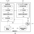
図2は、情報通信端末100の機能ブロック図である。ここに示す各ブロックは、ハードウェア的には、コンピュータのCPUをはじめとする素子や機械装置で実現でき、ソフトウェア的にはコンピュータプログラム等によって実現されるが、ここでは、それらの連携によって実現される機能ブロックを描いている。したがって、これらの機能ブロックはハードウェア、ソフトウェアの組合せによっていろいろなかたちで実現できることは、当業者には理解されるところである。
FIG. 2 is a functional block diagram of the
情報通信端末100は、通信部120、ユーザID取得部122、通信設定情報格納部124および端末情報格納部126を含む。通信部120は、外部との通信処理を行う。通信設定情報格納部124は、通信設定情報を格納する。端末情報格納部126は、端末情報を格納する。端末情報格納部126は、たとえば、ROM(Read Only Memory)であってもよい。ユーザID取得部122は、必要に応じてRFIDカード108からユーザIDを取得する。
The
通信部120は、対向無線通信部128とアクセスポイント通信部130を含む。対向無線通信部128は、非接触ICメモリリーダライタ110と無線通信によりデータを送受信する。情報通信端末100を非接触ICメモリリーダライタ110にかざすと、対向無線通信部128は端末情報格納部126が格納する端末情報を非接触ICメモリリーダライタ110に送信する。図1に関連して説明したようにユーザIDは、RFIDカード108から非接触ICメモリリーダライタ110に送信される。あるいは、ユーザID取得部122がユーザIDを取得して、対向無線通信部128が端末情報と併せてユーザIDを送信してもよい。
The
対向無線通信部128は、接続管理サーバ200から非接触ICメモリリーダライタ110を介して通信設定情報を受信し通信設定情報格納部124に格納する。アクセスポイント通信部130は、アクセスポイント112と無線通信によりデータを送受信する。アクセスポイント通信部130は、更に接続処理部132を含む。接続処理部132は、通信設定情報格納部124に格納される通信設定情報に基づいて、各アクセスポイント112との接続処理を実行する。
The opposing
図3は、接続管理サーバ200の機能ブロック図である。ここに示す各ブロックも、ハードウェア的には、コンピュータのCPUをはじめとする素子や機械装置で実現でき、ソフトウェア的にはコンピュータプログラム等によって実現されるが、ここでは、それらの連携によって実現される機能ブロックを描いている。したがって、これらの機能ブロックはハードウェア、ソフトウェアの組合せによっていろいろなかたちで実現できることは、当業者には理解されるところである。
FIG. 3 is a functional block diagram of the
接続管理サーバ200は、リーダライタインタフェース処理部202、接続管理部204、設定入力部206、登録ユーザ格納部208および接続設定情報格納部210を含む。リーダライタインタフェース処理部202は、非接触ICメモリリーダライタ110とのインタフェース処理を担当する。接続管理部204は、情報通信端末100のLAN106との接続を統括的に管理する。登録ユーザ格納部208は、登録ユーザのユーザIDを格納する。接続設定情報格納部210は、接続設定情報を格納する。接続設定情報格納部210のデータ構造については、図4に関連して後述する。設定入力部206は、接続設定情報について権限のあるユーザからの設定入力を受け付ける。この入力は、接続管理サーバ200のキーボードやマウスなどの入力デバイスを介してなされてもよいし、LAN106を介して外部からなされてもよい。入力データはそれぞれ、登録ユーザ格納部208や接続設定情報格納部210に格納される。また、ユーザからの入力ではなく接続管理サーバ200が乱数を利用して自動生成してもよい。
The
リーダライタインタフェース処理部202は、端末情報取得部220、ユーザID取得部222および通信設定情報送信部224を含む。端末情報取得部220は、情報通信端末100から端末情報を取得する。ユーザID取得部222は、RFIDカード108からユーザIDを取得する。通信設定情報送信部224は、通信設定情報生成部216が生成する通信設定情報を情報通信端末100に送信する。
The reader / writer
接続管理部204は、接続可否判定部212、メール送受信部214、通信設定情報生成部216および端末登録部218を含む。接続可否判定部212は、接続依頼操作に対する接続可否を判定する。登録ユーザでないユーザによる接続依頼操作の場合、接続可否判定部212は、情報通信端末100とLAN106との接続を許可しない。
The
メール送受信部214は、ユーザが各情報通信端末100を操作してデータを送受信するときの制限解除のために、管理者と電子メールを送受信する。本実施例においては、登録ユーザであっても、アクセスポイント112が管理するすべてのエリアにある機器(テレビ114、ハードディスクレコーダ116、パソコン118)をネットワーク経由にて操作できるわけではなく、所定の制限を受ける場合がある。以下、情報通信端末100を利用して、LAN106を介したアクセスポイント112が管理するすべてのエリアにある機器(テレビ114、ハードディスクレコーダ116、パソコン118)の操作をいうときには、「ネットワーク経由操作」とよぶ。たとえば、リビングルームのテレビ114やハードディスクレコーダ116は、登録ユーザであればだれでもネットワーク経由操作できるが、書斎のパソコン118は、一部の登録ユーザしかネットワーク経由操作できないとしてもよい。書斎のパソコン118をネットワーク経由操作する権限を有しないユーザが、ネットワーク経由操作を行おうとするとき、メール送受信部214は管理者として指定されたユーザに対して、許可を求める旨のメールを自動送信する。管理者から許可する旨のメールが受信されると、当該ユーザは当該情報通信端末100をネットワークに接続できるようになり、書斎のパソコン118をネットワーク経由操作できるようになる。更に詳しくは、次の図4以降に関連して後述する。通信設定情報生成部216は、接続依頼操作に対して接続を許可する場合に送信すべき通信設定情報を生成する。端末登録部218は、アクセスポイント112やゲートウェイ104、アクセスポイント112が管理する任意の機器(ハードディスクレコーダ116、パソコン118等)の中で、必要な機器に対して、各情報通信端末100の端末情報を登録する。
The mail transmission /
図4は、接続設定情報格納部210のデータ構造図である。アクセスポイントID欄230は、各アクセスポイント112を識別するアクセスポイントIDを示す。端末ID欄232は、端末IDを示す。管理者ID欄234は、各アクセスポイント112が担当するエリア140の管理者として設定されるユーザのユーザIDを示す。
FIG. 4 is a data structure diagram of the connection setting
管理者は、各情報通信端末100を操作する上で制限を受けない。管理者は、接続設定情報を設定変更する権限を有する。ファミリー権限欄236は、ファミリーユーザとして設定されるユーザの各情報通信端末100に対するネットワーク経由操作の権限を示す。ファミリーユーザは登録ユーザのうち、管理者以外のユーザである。ファミリーユーザは、各情報通信端末100をネットワーク経由操作する上で一定の制限を受ける。ゲスト権限欄238はゲストユーザとして設定されるユーザの各情報通信端末100におけるネットワーク経由操作の権限を示す。ゲストユーザは、ゲストカードとよばれるゲスト専用のユーザID(以下、「ゲストID」とよぶ)が記録されたRFIDカード108によって、各情報通信端末100をネットワーク経由操作する。すなわち、ゲストユーザは特殊な登録ユーザとして扱われる。ゲストユーザは、特別な登録ユーザとして情報通信端末100を操作可能である。ゲストユーザによるネットワーク経由操作も一定の制限を受ける。アドレス欄240は、管理者の電子メールアドレスを示す。
The administrator is not restricted in operating each
ユーザは、LAN106に接続された情報通信端末100を利用して、ネットワーク経由操作するときには、当該情報通信端末100と自己のRFIDカード108を、非接触ICメモリリーダライタ110にかざす。情報通信端末100は、受信した通信設定情報を利用してネットワークに接続する。更に、ユーザID取得部122により取得したユーザIDを利用して、任意の機器(ハードディスクレコーダ116、パソコン118等)に接続する。端末登録部218は、接続設定情報に基づいて、各機器に設定制御の為の情報を登録している。すなわち、情報通信端末100は、ネットワークに接続しても、ユーザIDに依存して、操作可能な機器が制限される。
When operating via the network using the
同図において、アクセスポイントID「01」のアクセスポイント112には、端末IDが「04」、「06」および「08」の3つの情報通信端末100が接続許可されている。たとえば、端末ID「04」の情報通信端末100を利用して、ユーザID「02」の管理者であるユーザがネットワーク経由操作をするとき、情報通信端末100は、端末ID「04」をアクセスポイントID「01」のアクセスポイント112に送信する。接続設定情報に従い、当該アクセスポイント112は、端末「04」に基づくデータの送受信を制限しない。続いて、ユーザID「02」に基づいて、任意の機器に接続する。そのため、この管理者であるユーザは、当該情報通信端末100を当該アクセスポイント112に接続させた上で、外部機器とデータを送受信可能となる。すなわち、当該ユーザは、当該情報通信端末100を制限無くネットワーク経由操作することができる。
In the figure, the access point 112 with the access point ID “01” is permitted to connect the three
一方、この情報通信端末100をユーザID「01」のファミリーユーザがネットワーク経由操作をする場合にも、情報通信端末100は端末ID「04」をアクセスポイント112に送信し、ユーザID「01」に基づいて、任意の機器に接続する。同図において、端末ID「04」の情報通信端末100のファミリーユーザによるネットワーク経由操作は、受信のみが許可されている。すなわち、ゲートウェイ104に受信のみ登録されており、外部機器からLAN106を経由してデータを受信することは可能であるが、データを外部に送信することはできない。この場合、当該情報通信端末100の接続対象となる任意の機器もしくはゲートウェイ104は、当該装置へのデータ転送は制限しないが、当該装置からのデータ転送を制限する。
On the other hand, also when the family user with the user ID “01” operates the
アクセスポイント112がデータ転送を制限するとき、アクセスポイント112は、対象となっている端末ID「04」を接続管理サーバ200に送信する。メール送受信部214は、端末ID「04」について、管理者として設定されているユーザの電子メールアドレスをアドレス欄240を参照して検出する。同図においては、「axa@xxx.com」である。この電子メールアドレスは、たとえば、管理者の携帯電話やノートパソコンなどのアドレスであってよい。
When the access point 112 restricts data transfer, the access point 112 transmits the target terminal ID “04” to the
メール送受信部214は、この電子メールアドレスを送信先として、データ転送許可を依頼する旨の電子メールを自動送信する。メール送受信部214は、管理者により接続を許可する旨の回答を受信すると、当該アクセスポイント112にこれを通知する。これにより、アクセスポイント112の設定は一時的に変更され、ファミリーユーザであっても端末ID「04」を介して外部へデータ送信できるようになる。同図において、ゲストユーザは端末ID「04」の情報通信端末100をアクセスポイント112に接続させることはできないが、この場合にも、管理者からの許可があれば一時的に接続を許可される。
The mail transmitting / receiving
より具体的な一例として、たとえば、ユーザがネットワーク接続機能を有するデジタルカメラによりパーソナルコンピュータに保存されている画像を参照したり、撮影した画像を保存する場合を示す。このときユーザはRFIDカード108とデジタルカメラを、非接触ICメモリリーダライタ110にかざして、デジタルカメラはRFIDカード108のユーザIDの権限で接続設定情報と通信設定情報を読み取り、端末情報(端末ID)を報告する。ここで接続管理サーバ200は、管理者に対して、ネットワーク接続報告する為、電子メールを送信し、管理者から接続許可する旨の回答を受信する。接続管理サーバ200は、接続許可のメールを受信すると、該当するアクセスポイント112に、端末情報を登録する。デジタルカメラは、読み取った通信設定情報を利用してネットワークに接続し、更に、読み取ったユーザIDを利用して、パーソナルコンピュータにログインする。こうしてデジタルカメラは、保存されている画像を参照したり、撮影した画像を保存する。
As a more specific example, for example, a case where a user refers to an image stored in a personal computer by a digital camera having a network connection function or stores a photographed image is shown. At this time, the user holds the
図1に基づいて説明すれば、このとき該当するアクセスポイント112が、デジタルカメラがネットワークに接続させるか否かを判定する。管理者から接続許可メールを受信している場合、ネットワーク接続可能となり、当該ユーザIDがパーソナルコンピュータ118に対するログイン権限を有していれば、パーソナルコンピュータ118内の画像データ等を、送受信することが可能となる。一方、管理者から接続許可メールを受信していない場合は、たとえ当該ユーザIDが、パーソナルコンピュータ118に対するログイン権限を有している場合でも、ネットワーク接続できない為、パーソナルコンピュータ118内の画像データ等を、利用することができない。
Referring to FIG. 1, the corresponding access point 112 at this time determines whether or not the digital camera is connected to the network. When the connection permission mail is received from the administrator, it is possible to connect to the network, and if the user ID has the login authority for the
このように、端末情報(端末ID)によって、アクセスポイント112に対する接続可否を簡単に管理する為、不正なアクセスを防止しやすい。また、電子メールを利用した管理者に対する確認により、予め設定された接続設定情報に関わらず、柔軟に通信システム300を運用することができる。
In this way, whether or not the connection to the access point 112 is easily managed based on the terminal information (terminal ID), it is easy to prevent unauthorized access. In addition, the
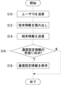
図5は、情報通信端末100をLAN106に接続させるときの情報通信端末100を中心とした処理過程を示すフローチャートである。ユーザが情報通信端末100とRFIDカード108を非接触ICメモリリーダライタ110にかざすとき、RFIDカード108からユーザIDが非接触ICメモリリーダライタ110に送信される(S10)。ユーザID取得部122がRFIDカード108からユーザIDを取得し、対向無線通信部128がこれを送信してもよい。通信部120は、端末情報格納部126から端末情報を読み出す(S12)。対向無線通信部128は、読み出された端末情報を非接触ICメモリリーダライタ110に送信する(S14)。
FIG. 5 is a flowchart showing a processing process centered on the
対向無線通信部128は、非接触ICメモリリーダライタ110を介して接続管理サーバ200から通信設定情報を受信する。所定時間内に受信できなければ(S16のN)、接続失敗として処理は終了する。接続管理サーバ200の接続可否判定部212は、非接触ICメモリリーダライタ110を介して受信したユーザIDが、登録ユーザのユーザIDでない場合には、通信設定情報送信を拒否する。対向無線通信部128が、接続管理サーバ200から通信設定情報の受信に成功すると(S16のY)、対向無線通信部128は通信設定情報を通信設定情報格納部124に保存する(S18)。情報通信端末100は、各エリア140内においてそのエリアを担当するアクセスポイント112に接続処理を実行する。ただし、図4に関連して説明したように、接続が許可されていない場合には、アクセスポイント112により接続拒否される。
The opposing
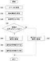
図6は、情報通信端末100をLAN106に接続させるときの接続管理サーバ200の処理過程を示すフローチャートである。ユーザが、RFIDカード108と情報通信端末100を非接触ICメモリリーダライタ110にかざすと、ユーザID取得部222は、非接触ICメモリリーダライタ110を介してユーザIDを受信する(S30)。端末情報取得部220は、同様に非接触ICメモリリーダライタ110を介して端末IDを受信する(S32)。接続可否判定部212は、ユーザIDが登録ユーザのユーザIDであるか判定して、当該ユーザによる情報通信端末100の接続可否を判定する(S34)。接続が許可されると(S36のY)、端末登録部218は各アクセスポイント112に対して当該情報通信端末100に関する端末ID等の接続設定情報を接続設定情報格納部210から読み出して登録する(S44)。次に、通信設定情報生成部216は情報通信端末100がLAN106と接続するための設定である通信設定情報を生成する(S46)。通信設定情報送信部224は、非接触ICメモリリーダライタ110からその通信設定情報を送信する(S48)。
FIG. 6 is a flowchart showing the process of the
一方、S36において、接続が許可されていなければ(S36のN)、端末登録部218は各アクセスポイント112に当該情報通信端末100の端末IDを接続が許可されない情報通信端末100として登録する(S42)。これにより当該情報通信端末100はLAN106のいずれのアクセスポイント112とも接続不能となり、不正に情報通信端末100がLAN106と接続されないように処置される。
On the other hand, if the connection is not permitted in S36 (N in S36), the
以上、実施例にもとづいて、本発明を説明した。本実施例によれば、RFIDなどのユーザに負担のかからないユーザインタフェースにより、ネットワークに接続するための設定を簡単に行うことができる。また、ユーザIDによって、情報通信端末100の使用者を認識することにより、ユーザに応じた情報通信端末100の制御が可能となる。
The present invention has been described above based on the embodiments. According to the present embodiment, setting for connecting to a network can be easily performed by a user interface that does not burden the user such as RFID. Further, by recognizing the user of the
以上、実施の形態をもとに本発明を説明した。なお本発明はこの実施の形態に限定されることなく、そのさまざまな変形例もまた、本発明の態様として有効である。 The present invention has been described above based on the embodiment. The present invention is not limited to this embodiment, and various modifications thereof are also effective as aspects of the present invention.
本実施例においては、接続管理サーバ200の接続可否判定部は、非接触ICメモリリーダライタ110にアクセスしてきたユーザが登録ユーザやゲストユーザでなければ、情報通信端末100の接続を許可しないとして説明した。
これとは別に、アクセスしてきたユーザが登録ユーザやゲストユーザであるか否かにかかわらず、情報通信端末100は無線LAN106と接続可能としてもよい。端末情報は各アクセスポイント112に一旦登録され、情報通信端末100には、非接触ICメモリリーダライタ110を介して通信設定情報が送信される。
In the present embodiment, the connection possibility determination unit of the
Apart from this, the
情報通信端末100が非接触ICメモリリーダライタ110に端末情報を送信すると、接続管理サーバ200は、予め管理者として登録しているユーザに対し、接続がなされた旨を電子メールにて通知する。このメールには、接続してきたユーザ名や端末名などについて記載される。管理者は、電子メールを確認し、接続を許可してもよい場合には、その旨を返信する。あるいは、所定時間返信しないことを以て許可としてもよい。接続させたくないときには、管理者は所定のフォームにて不許可の旨を示す電子メールを接続管理サーバ200に送信する。接続管理サーバ200は、管理者から接続不許可の旨の電子メールを受信すると、各アクセスポイント112のMACアドレスフィルタを制御して、当該情報通信端末100の接続を拒否するように設定変更してもよい。このような方法により、管理者が認めないユーザによる無線LAN106へのアクセスを制限することができる。
When the
本実施例においては、各情報通信端末100についてのネットワーク経由操作を対象として説明したが、各情報通信端末100の各機能に対してユーザごとの権限がさだめられてもよい。たとえば、ハードディスクレコーダに記録されるデータの一部しか読み出せないユーザと、すべてを読み出せるユーザが設定されてもよい。これにより、各情報通信端末100の有するデータをきめ細かく制御することができる。
In the present embodiment, the operation via the network for each
100 情報通信端末、106 LAN、108 RFIDカード、110 非接触ICメモリリーダライタ、112 アクセスポイント、120 通信部、122 ユーザID取得部、124 通信設定情報格納部、126 端末情報格納部、128 対向無線通信部、130 アクセスポイント通信部、132 接続処理部、200 接続管理サーバ、202 リーダライタインタフェース処理部、204 接続管理部、206 設定入力部、208 登録ユーザ格納部、210 接続設定情報格納部、212 接続可否判定部、214 メール送受信部、216 通信設定情報生成部、218 端末登録部、220 端末情報取得部、222 ユーザID取得部、224 通信設定情報送信部、300 通信システム。
100 information communication terminal, 106 LAN, 108 RFID card, 110 contactless IC memory reader / writer, 112 access point, 120 communication unit, 122 user ID acquisition unit, 124 communication setting information storage unit, 126 terminal information storage unit, 128 opposed
Claims (6)
所定の構内通信網において当該端末装置を識別するために必要とされる情報である端末IDを記憶する端末ID記憶部と、
当該端末装置と前記構内通信網の接続を支援する接続支援装置に対し、近距離無線通信によって前記端末IDを送信する端末ID送信部と、
前記接続支援装置を介して前記端末IDを受信した接続管理サーバから、当該端末装置が前記構内通信網と接続するために必要とする通信設定情報を前記接続支援装置を介した近距離無線通信により受信する通信設定情報受信部と、
前記通信設定情報に基づいて、前記構内通信網と接続する接続処理部と、
を備えることを特徴とする通信端末装置。 A communication terminal device having a communication function,
A terminal ID storage unit for storing a terminal ID, which is information required for identifying the terminal device in a predetermined local area communication network;
A terminal ID transmission unit that transmits the terminal ID by short-range wireless communication to a connection support device that supports connection between the terminal device and the local communication network
From the connection management server that has received the terminal ID via the connection support device, communication setting information required for the terminal device to connect to the local communication network is obtained by short-range wireless communication via the connection support device. A communication setting information receiving unit for receiving;
Based on the communication setting information, a connection processing unit connected to the local communication network;
A communication terminal device comprising:
近距離無線通信によって前記ユーザIDを前記接続支援装置に対して送信するユーザID送信部と、を更に備えることを特徴とする請求項1に記載の通信端末装置。 A user ID input unit for receiving an input of a user ID, which is information required for identifying the user in the local area communication network;
The communication terminal apparatus according to claim 1, further comprising: a user ID transmission unit that transmits the user ID to the connection support apparatus by short-range wireless communication.
前記通信端末装置が前記構内通信網に接続するために必要とする通信設定情報を生成する通信設定情報生成部と、
前記生成された通信設定情報を、前記接続支援装置を介して前記通信端末装置に送信する通信設定情報送信部と、
を備えることを特徴とする接続管理サーバ。 A terminal ID, which is information required for identifying a communication terminal device in a predetermined local communication network, is transmitted from the communication terminal device via a connection support device that supports connection between the communication terminal device and the local communication network. A terminal ID receiving unit for receiving;
A communication setting information generating unit that generates communication setting information required for the communication terminal device to connect to the local communication network;
A communication setting information transmitting unit for transmitting the generated communication setting information to the communication terminal device via the connection support device;
A connection management server comprising:
請求項3に記載の接続管理サーバと、
近距離無線通信により前記通信端末装置とデータを送受信することにより、前記通信端末装置と前記構内通信網との接続を支援する接続支援装置と、
を備えることを特徴とする通信システム。 A communication terminal device according to claim 1;
A connection management server according to claim 3;
A connection support device for supporting connection between the communication terminal device and the local communication network by transmitting and receiving data to and from the communication terminal device by short-range wireless communication;
A communication system comprising:
所定の構内通信網において前記通信端末装置を識別するために必要とされる情報である端末IDを記憶する機能と、
前記通信端末装置と前記構内通信網の接続を支援する接続支援装置に対し、近距離無線通信によって前記端末IDを送信する機能と、
前記接続支援装置を介して前記端末IDを受信した接続管理サーバから、前記通信端末装置が前記構内通信網と接続するために必要とする通信設定情報を前記接続支援装置を介した近距離無線通信により受信する機能と、
前記通信設定情報に基づいて、前記構内通信網と接続する機能と、
をコンピュータに発揮させることを特徴とする通信プログラム。 A computer program for controlling a communication terminal device,
A function of storing a terminal ID, which is information required to identify the communication terminal device in a predetermined local area communication network;
A function of transmitting the terminal ID by short-range wireless communication to a connection support device that supports connection between the communication terminal device and the local communication network;
Short-range wireless communication via the connection support device from the connection management server that has received the terminal ID via the connection support device, the communication setting information required for the communication terminal device to connect to the local communication network With the function to receive by
Based on the communication setting information, a function of connecting to the local communication network;
A communication program characterized by causing a computer to exhibit the above.
前記通信端末装置が前記構内通信網に接続するために必要とする通信設定情報を生成する機能と、
前記生成された通信設定情報を、前記接続支援装置を介して前記通信端末装置に送信する機能と、
をコンピュータに発揮させることを特徴とする接続管理プログラム。 A terminal ID, which is information required for identifying a communication terminal device in a predetermined local communication network, is transmitted from the communication terminal device via a connection support device that supports connection between the communication terminal device and the local communication network. The function to receive,
A function of generating communication setting information required for the communication terminal device to connect to the local communication network;
A function of transmitting the generated communication setting information to the communication terminal device via the connection support device;
A connection management program characterized by causing a computer to perform the operation.
Priority Applications (1)
| Application Number | Priority Date | Filing Date | Title |
|---|---|---|---|
| JP2004169438A JP2005354136A (en) | 2004-06-08 | 2004-06-08 | Communication terminal, connection management server and communication system |
Applications Claiming Priority (1)
| Application Number | Priority Date | Filing Date | Title |
|---|---|---|---|
| JP2004169438A JP2005354136A (en) | 2004-06-08 | 2004-06-08 | Communication terminal, connection management server and communication system |
Publications (2)
| Publication Number | Publication Date |
|---|---|
| JP2005354136A true JP2005354136A (en) | 2005-12-22 |
| JP2005354136A5 JP2005354136A5 (en) | 2007-07-05 |
Family
ID=35588257
Family Applications (1)
| Application Number | Title | Priority Date | Filing Date |
|---|---|---|---|
| JP2004169438A Pending JP2005354136A (en) | 2004-06-08 | 2004-06-08 | Communication terminal, connection management server and communication system |
Country Status (1)
| Country | Link |
|---|---|
| JP (1) | JP2005354136A (en) |
Cited By (12)
| Publication number | Priority date | Publication date | Assignee | Title |
|---|---|---|---|---|
| JP2009055505A (en) * | 2007-08-29 | 2009-03-12 | Nec Infrontia Corp | Personal digital assistant specific information setting system, personal digital assistant, specific information setting method, program therefor and recording medium |
| JP2009232057A (en) * | 2008-03-21 | 2009-10-08 | Kenwood Corp | Radio apparatus and radio receiving method |
| JP2010170575A (en) * | 2005-01-21 | 2010-08-05 | Fineart Technology Co Ltd | Method of controlling data transfer and computer readable recording medium |
| JP2012182679A (en) * | 2011-03-01 | 2012-09-20 | Nec Access Technica Ltd | Home gateway device, home gateway device control method and control program thereof |
| JP2012186516A (en) * | 2011-03-03 | 2012-09-27 | Silex Technology Inc | Wireless lan device setting system |
| CN102867390A (en) * | 2012-09-27 | 2013-01-09 | 上海北大方正科技电脑系统有限公司 | Realization method and system for monitoring man-machine separation of community correction personnel |
| JP2013191216A (en) * | 2007-12-28 | 2013-09-26 | Panasonic Corp | Communication device |
| JP2014033352A (en) * | 2012-08-03 | 2014-02-20 | Nec Commun Syst Ltd | Communication control system, communication terminal, communication control server, communication control method, and program therefor |
| JPWO2013153925A1 (en) * | 2012-04-10 | 2015-12-17 | ソニー株式会社 | COMMUNICATION DEVICE, COMMUNICATION CONTROL METHOD, AND PROGRAM |
| JP2017139726A (en) * | 2015-09-14 | 2017-08-10 | ザ・ボーイング・カンパニーThe Boeing Company | System and method for providing secure access to wireless network |
| JP2018133827A (en) * | 2013-01-18 | 2018-08-23 | 株式会社リコー | Communication system and communication terminal |
| CN110070673A (en) * | 2018-01-24 | 2019-07-30 | 豪星工业有限公司 | Intelligent drinking-water system |
Citations (3)
| Publication number | Priority date | Publication date | Assignee | Title |
|---|---|---|---|---|
| JP2002045573A (en) * | 2000-08-02 | 2002-02-12 | Casio Comput Co Ltd | Network system, communication competition system, and storage medium wherein competition service program is stored |
| JP2002351766A (en) * | 2001-05-29 | 2002-12-06 | Denso Corp | Setting file transmission system and transmitting method for setting file |
| JP2003032175A (en) * | 2001-07-18 | 2003-01-31 | Sony Corp | Communication system and method, information processing unit and method, communication terminal and method, extension device, and program |
-
2004
- 2004-06-08 JP JP2004169438A patent/JP2005354136A/en active Pending
Patent Citations (3)
| Publication number | Priority date | Publication date | Assignee | Title |
|---|---|---|---|---|
| JP2002045573A (en) * | 2000-08-02 | 2002-02-12 | Casio Comput Co Ltd | Network system, communication competition system, and storage medium wherein competition service program is stored |
| JP2002351766A (en) * | 2001-05-29 | 2002-12-06 | Denso Corp | Setting file transmission system and transmitting method for setting file |
| JP2003032175A (en) * | 2001-07-18 | 2003-01-31 | Sony Corp | Communication system and method, information processing unit and method, communication terminal and method, extension device, and program |
Cited By (15)
| Publication number | Priority date | Publication date | Assignee | Title |
|---|---|---|---|---|
| JP2010170575A (en) * | 2005-01-21 | 2010-08-05 | Fineart Technology Co Ltd | Method of controlling data transfer and computer readable recording medium |
| JP2009055505A (en) * | 2007-08-29 | 2009-03-12 | Nec Infrontia Corp | Personal digital assistant specific information setting system, personal digital assistant, specific information setting method, program therefor and recording medium |
| US9477860B2 (en) | 2007-12-28 | 2016-10-25 | Panasonic Intellectual Property Corporation Of America | Communication device, communication system, image presentation method, and program |
| JP2013191216A (en) * | 2007-12-28 | 2013-09-26 | Panasonic Corp | Communication device |
| JP2009232057A (en) * | 2008-03-21 | 2009-10-08 | Kenwood Corp | Radio apparatus and radio receiving method |
| JP2012182679A (en) * | 2011-03-01 | 2012-09-20 | Nec Access Technica Ltd | Home gateway device, home gateway device control method and control program thereof |
| JP2012186516A (en) * | 2011-03-03 | 2012-09-27 | Silex Technology Inc | Wireless lan device setting system |
| JPWO2013153925A1 (en) * | 2012-04-10 | 2015-12-17 | ソニー株式会社 | COMMUNICATION DEVICE, COMMUNICATION CONTROL METHOD, AND PROGRAM |
| US9913107B2 (en) | 2012-04-10 | 2018-03-06 | Sony Corporation | Communication device, communication control method, and program |
| US10687177B2 (en) | 2012-04-10 | 2020-06-16 | Sony Corporation | Communication device, communication control method, and program |
| JP2014033352A (en) * | 2012-08-03 | 2014-02-20 | Nec Commun Syst Ltd | Communication control system, communication terminal, communication control server, communication control method, and program therefor |
| CN102867390A (en) * | 2012-09-27 | 2013-01-09 | 上海北大方正科技电脑系统有限公司 | Realization method and system for monitoring man-machine separation of community correction personnel |
| JP2018133827A (en) * | 2013-01-18 | 2018-08-23 | 株式会社リコー | Communication system and communication terminal |
| JP2017139726A (en) * | 2015-09-14 | 2017-08-10 | ザ・ボーイング・カンパニーThe Boeing Company | System and method for providing secure access to wireless network |
| CN110070673A (en) * | 2018-01-24 | 2019-07-30 | 豪星工业有限公司 | Intelligent drinking-water system |
Similar Documents
| Publication | Publication Date | Title |
|---|---|---|
| US8265004B2 (en) | Transferring data using ad hoc networks | |
| US9678693B2 (en) | Method of setting wireless connection via near field communication function and image forming apparatus for performing the method | |
| JP6599341B2 (en) | Method, device and system for dynamic network access management | |
| US8151319B2 (en) | Authentication of devices in a wireless network | |
| US7903646B2 (en) | Wireless communication system allowing group identification information to be publicly available and to be hidden, wireless access point device, and communication method and program for wireless access point device | |
| US20150172925A1 (en) | Method and Apparatus for Wireless Network Access Parameter Sharing | |
| US20090183241A1 (en) | Device Ownership Transfer From A Network | |
| US20150085848A1 (en) | Method and Apparatus for Controlling Wireless Network Access Parameter Sharing | |
| JP2007528057A (en) | Guest dongle and method of connecting guest device to wireless home network | |
| JP2005142792A (en) | Connection information setting method and wireless communication terminal | |
| EP1629634B1 (en) | Secure authentication in a wireless home network | |
| JP2014509468A (en) | Method and system for out-of-band delivery of wireless network credentials | |
| JP2005354136A (en) | Communication terminal, connection management server and communication system | |
| JP2009512368A (en) | Communication system and communication method | |
| EP2741465B1 (en) | Method and device for managing secure communications in dynamic network environments | |
| JP2006350726A (en) | Access right control method | |
| JP4303905B2 (en) | Wireless communication system switching device | |
| JP2008022208A (en) | System, method and program for mutual authentication | |
| JP2021158494A (en) | Communication system, electronic device, and program | |
| US20100293300A1 (en) | Communication apparatus, control method of communication apparatus, and program | |
| JP5545433B2 (en) | Portable electronic device and operation control method for portable electronic device | |
| JP5141096B2 (en) | Automatic file encryption apparatus using acquired network connection information, method and program thereof | |
| WO2014009391A1 (en) | A method and a system for transferring access point passwords | |
| KR20070096488A (en) | Automatic authentication method between bluetooth devices | |
| JP6704380B2 (en) | External server, communication system and communication method |
Legal Events
| Date | Code | Title | Description |
|---|---|---|---|
| A521 | Request for written amendment filed |
Free format text: JAPANESE INTERMEDIATE CODE: A523 Effective date: 20070521 |
|
| A621 | Written request for application examination |
Free format text: JAPANESE INTERMEDIATE CODE: A621 Effective date: 20070530 |
|
| A977 | Report on retrieval |
Free format text: JAPANESE INTERMEDIATE CODE: A971007 Effective date: 20091203 |
|
| A131 | Notification of reasons for refusal |
Free format text: JAPANESE INTERMEDIATE CODE: A131 Effective date: 20091215 |
|
| A02 | Decision of refusal |
Free format text: JAPANESE INTERMEDIATE CODE: A02 Effective date: 20100608 |