JP2005348494A - Dynamo-electric machine - Google Patents
Dynamo-electric machine Download PDFInfo
- Publication number
- JP2005348494A JP2005348494A JP2004164057A JP2004164057A JP2005348494A JP 2005348494 A JP2005348494 A JP 2005348494A JP 2004164057 A JP2004164057 A JP 2004164057A JP 2004164057 A JP2004164057 A JP 2004164057A JP 2005348494 A JP2005348494 A JP 2005348494A
- Authority
- JP
- Japan
- Prior art keywords
- electrical machine
- rotating electrical
- heat sink
- switching
- switching element
- Prior art date
- Legal status (The legal status is an assumption and is not a legal conclusion. Google has not performed a legal analysis and makes no representation as to the accuracy of the status listed.)
- Pending
Links
Images


Abstract
Description
この発明は、インバータ制御等を行うパワー素子ユニットを搭載した回転電機、例えば車両用回転電機の構造に関するものである。 The present invention relates to a structure of a rotating electrical machine, for example, a rotating electrical machine for a vehicle, on which a power element unit that performs inverter control or the like is mounted.
従来、一般的に、回転電機をインバータ制御等するパワー素子ユニットは、当該回転電機から離して設置されていた。そのため、パワー素子ユニットと回転電機との間を電気的に接続する交流配線の長さが長くなり、配線抵抗が高くなって電圧降下が増加するので、回転電機のトルクが低下したり、回転速度が低下するという問題があった。特に、12Vや36Vの低電圧を電源とする車両用回転電機においては電圧低下の影響が大きく、例えば0.5Vの電圧降下があったとすると約4%の電源電圧のロスとなる。また、電圧降下を抑制するために配線を太くするという処置が考えられるが、配線の重量が増加し、またコストが増加する問題がある。 Conventionally, in general, a power element unit that performs inverter control or the like on a rotating electrical machine has been installed away from the rotating electrical machine. As a result, the length of the AC wiring that electrically connects the power element unit and the rotating electrical machine becomes longer, the wiring resistance increases, and the voltage drop increases, so the torque of the rotating electrical machine decreases and the rotational speed decreases. There was a problem that decreased. In particular, in a rotating electrical machine for a vehicle using a low voltage of 12V or 36V as a power source, the influence of the voltage drop is large. For example, if there is a voltage drop of 0.5V, the power supply voltage loss is about 4%. Further, although a measure of thickening the wiring in order to suppress the voltage drop can be considered, there is a problem that the weight of the wiring increases and the cost increases.
また、低電圧電源の回転電機でなくても、パワー素子ユニットと回転電機が離れて配置されると、その間を長い配線により接続する必要があり、製品のレイアウトの制約になるだけでなく、配線の部品コストや取り付けコストが増加する。 Even if the rotating element is not a low-voltage power rotating machine, if the power element unit and the rotating electric machine are placed apart from each other, it is necessary to connect them with long wires, which not only restricts the layout of the product but also the wiring. The parts cost and installation cost increase.
そこで、例えば特許文献1のように、インバータユニットを車両用回転電機に一体的に取付けられるものがあった。そこでは、インバータユニットをリヤブラケットに一体的に取付けることにより、接続するハーネス類を短くでき、電圧降下を抑制して回転電機のトルク特性、回転数特性を改善する効果を奏する。また、ハーネスの重量軽減や耐外乱ノイズ性の向上が図られる。 Therefore, for example, as in Patent Document 1, there is one in which an inverter unit can be integrally attached to a vehicular rotating electrical machine. In this case, by connecting the inverter unit integrally to the rear bracket, the harnesses to be connected can be shortened, and the voltage drop can be suppressed and the torque characteristics and the rotational speed characteristics of the rotating electrical machine can be improved. In addition, the weight of the harness can be reduced and the noise resistance can be improved.
しかしながら、特許文献1等に示すように、インバータユニットを回転電機の近傍に配置するにあたって、パワー素子の放熱性を確保する必要があった。また、回転電機自体が発熱するのでその周囲の温度環境は厳しく、発熱体であるパワー素子を含む制御回路を回転電機付近に配置することでさらに温度が上昇し、パワー素子や制御素子を破壊するという問題があった。さらに、回転電機のスペースにパワー素子ユニットを追加して設置するために装置全体が大型化する問題があった。 However, as shown in Patent Document 1 and the like, it is necessary to ensure the heat dissipation of the power element when arranging the inverter unit in the vicinity of the rotating electrical machine. Moreover, since the rotating electrical machine itself generates heat, the ambient temperature environment is severe, and by placing a control circuit including a power element that is a heating element near the rotating electrical machine, the temperature further rises and the power element and the control element are destroyed. There was a problem. Furthermore, since the power element unit is additionally installed in the space of the rotating electrical machine, there is a problem that the entire apparatus is increased in size.
この発明は、前記のような課題を解消するためになされたものであり、インバータユニット等のパワー素子ユニットを回転電機に近接するにあたって、パワー素子の放熱性を充分に確保することを目的とする。 The present invention has been made to solve the above-described problems, and an object thereof is to ensure sufficient heat dissipation of a power element when a power element unit such as an inverter unit is brought close to a rotating electrical machine. .
また、回転電機のスペースにパワー素子ユニットを追加して設置しても、装置全体が大型化しないようにする。 Moreover, even if a power element unit is added and installed in the space of the rotating electrical machine, the entire apparatus is not enlarged.
この発明に係る回転電機は、回転自在に配設された回転子と、この回転子を囲むように配設され電機子巻線を有する固定子とを備えた回転電機部と、回転電機部に一体的または近接して設けられるとともに、少なくとも上アームおよび下アームを構成する一対のスイッチング素子を備えて回転電機部のスイッチング制御を行うスイッチング回路部(パワー素子ユニット部)とを備え、スイッチング回路部の上アームおよび下アームのスイッチング素子の両方のドレイン端子が絶縁物を介することなく別々のヒートシンクに接続されていることを特徴とする。 A rotating electrical machine according to the present invention includes: a rotating electrical machine unit including a rotor that is rotatably disposed; and a stator that is disposed so as to surround the rotor and has an armature winding; A switching circuit unit that is provided integrally or in close proximity, and includes a switching circuit unit (power element unit unit) that includes at least a pair of switching elements that constitute an upper arm and a lower arm and performs switching control of the rotating electrical machine unit. The drain terminals of both the switching elements of the upper arm and the lower arm are connected to separate heat sinks without passing through an insulator.
特に、これら別々のヒートシンクは、バッテリの正極側電位に接続されるとともに上アームのスイッチング素子のドレイン端子が接続される第1のヒートシンク(内側ヒートシンク)と、電機子巻線の各相電位に接続されるとともに下アームのスイッチング素子のドレイン端子が接続される第2のヒートシンク(外側ヒートシンク)とする。 In particular, these separate heat sinks are connected to the first heat sink (inner heat sink) connected to the positive side potential of the battery and to the drain terminal of the switching element of the upper arm, and to each phase potential of the armature winding. And a second heat sink (outside heat sink) to which the drain terminal of the switching element of the lower arm is connected.
また、この発明に係る回転電機は、回転自在に配設された回転子と、この回転子を囲むように配設され電機子巻線を有する固定子とを備えた回転電機部と、回転電機部に一体的または近接して設けられるとともに、少なくとも上アームおよび下アームを構成する一対のスイッチング素子を備えて回転電機部のスイッチング制御を行うスイッチング回路部(パワー素子ユニット部)とを備え、スイッチング回路部の上アームまたは下アームのスイッチング素子のいずれかのドレイン端子が絶縁物を介することなくヒートシンクに接続されていることを特徴とする。 In addition, a rotating electrical machine according to the present invention includes a rotating electrical machine unit including a rotor that is rotatably disposed, and a stator that is disposed so as to surround the rotor and has an armature winding, and the rotating electrical machine. A switching circuit portion (power element unit portion) that is provided integrally with or close to the portion and includes at least a pair of switching elements that constitute the upper arm and the lower arm, and performs switching control of the rotating electrical machine portion. The drain terminal of either the switching element of the upper arm or the lower arm of the circuit unit is connected to the heat sink without an insulator.
特に、このヒートシンクは、バッテリの正極側電位に接続されるとともに上アームのスイッチング素子のドレイン端子が接続されるヒートシンクである。 In particular, this heat sink is a heat sink to which the drain terminal of the switching element of the upper arm is connected while being connected to the positive side potential of the battery.
この発明に係る回転電機によれば、パワー素子であるスイッチング素子とヒートシンクの間の絶縁層が不要となるので熱伝導率を向上することができる。その結果、スイッチング素子の放熱量が向上し、パワー素子ユニットの冷却性が向上する。 According to the rotating electrical machine according to the present invention, since an insulating layer between the switching element as a power element and the heat sink is not necessary, the thermal conductivity can be improved. As a result, the heat dissipation amount of the switching element is improved, and the cooling performance of the power element unit is improved.
ヒートシンクを配線として使用することができるので、配線部品の部品点数を少なくでき、また、配線基板自体も小型化することができ、装置全体の小型化が図れる。 Since the heat sink can be used as the wiring, the number of wiring components can be reduced, and the wiring board itself can be reduced in size, so that the entire apparatus can be reduced in size.
パワー素子ユニット部の小型化により、風路が確保され有効な冷却が実施されるので全体の冷却性を確保できる。また、制御回路等と一体にすることができ、接続のケーブル機器が省略できるので、システムとして安価にすることができ、また、故障確率を低減できるという効果がある。 By reducing the size of the power element unit, the air path is secured and effective cooling is performed, so that the entire cooling performance can be secured. In addition, since it can be integrated with a control circuit and the like and the connected cable device can be omitted, the system can be made inexpensive and the failure probability can be reduced.
以下、この発明を実施するための最良の形態を図に基づいて詳細に説明する。 Hereinafter, the best mode for carrying out the present invention will be described in detail with reference to the drawings.
実施の形態1.
図1はこの発明の実施の形態1による回転電機の構造を示す断面図であり、当該回転電機に一体的または近接してパワー素子ユニットを配置している。
Embodiment 1 FIG.
FIG. 1 is a cross-sectional view showing the structure of a rotating electrical machine according to Embodiment 1 of the present invention, in which a power element unit is disposed integrally or in proximity to the rotating electrical machine.
図1において、回転電機10は、フロントブラケット(図示せず)及びリヤブラケット11からなるケースと、当該ケースに支持用ベアリング12を介して回転自在に配設されているシャフト13と、このシャフト13に固定されると共に界磁巻線14を有する回転子15と、前記ケースに固定されて回転子15を囲むように配設されると共に電機子巻線16aを有する固定子16と、回転子15の軸方向の両端面に固定されたファン17と、シャフト13のフロント側の端部に固着されたプーリ18と、シャフト13のリヤ側外周に位置するようにリヤブラケット11に取り付けられたブラシホルダ19と、シャフト13のリヤ側に装着された一対のスリップリング21に摺接するようにブラシホルダ19内に配設された一対のブラシ20と、シャフト13のリヤ側端部に配設された回転位置検出センサ(レゾルバ等)22を備えている。そして、この回転電機10はプーリ18及びベルト(図示せず)を介してエンジンの回転軸(図示せず)に連結されている。
In FIG. 1, a rotating
本実施の形態では、回転電機10に一体的または近接してパワー素子ユニット4が設置されている。すなわち、リヤブラケット11のリヤ側に配設したカバー30の内側に、パワー素子ユニット4を構成する複数のパワー素子(後述するスイッチング素子)41と、各パワー素子41に接続された内側ヒートシンク50及び外側ヒートシンク51が設置されている。これらパワー素子41、内側ヒートシンク50、外側ヒートシンク51のレイアウトについては、後述の図3および図4により詳述する。また、カバー30の内側には、後述する制御回路44を搭載した制御回路基板44aと、電機子巻線16aの配線を外側ヒートシンク51に接続すると共にパワー素子ユニット4の端子をアースに接続するための結線板55が配設されている。さらに、カバー30およびリヤブラケット11には通風孔30a、11aが設けられ、回転子15のファン17の回転により、図示矢印Fのような風がカバー30内部を通り抜け、パワー素子41、内側ヒートシンク50、外側ヒートシンク51、制御回路44、結線板55を冷却する。
In the present embodiment, the
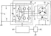
図2はパワー素子ユニットを備えた回転電機の動作を説明するための概略回路図である。図2において、回転電機10は、固定子16の電機子巻線16aと、回転子15の界磁巻線14を備え、回転子15に連結されたプーリ18がエンジン(図示せず)の回転軸とベルトにより連結されている。ここで、電機子巻線16aは、3相(U相、V相、W相)のコイルをY結線(スター結線)して構成されている。パワー素子ユニット4は、複数のパワー素子であるスイッチング素子(パワートランジスタ、MOSFET、IGBT等)41と各スイッチング素子41に並列に接続されたダイオード42からなるインバータモジュール40と、このインバータモジュール40に並列に接続されたコンデンサ43とを備えている。インバータモジュール40は、上アーム46を構成するスイッチング素子41およびダイオード42と、下アーム47を構成するスイッチング素子41およびダイオード42とを2組直列に接続したものを1セットとし、当該セットが3個並列に配置されている。
FIG. 2 is a schematic circuit diagram for explaining the operation of the rotating electrical machine including the power element unit. In FIG. 2, the rotating
電機子巻線16aのY結線の各相の端部は、交流配線9を介して前記直列に配置した上アーム46のスイッチング素子41と下アーム47のスイッチング素子41の中間点にそれぞれ電気的に接続されている。また、バッテリ5の正極側端子および負極側端子が、直列配線8を介してインバータモジュール40の正極側および負極側にそれぞれ電気的に接続されている。
The ends of each phase of the Y connection of the armature winding 16a are electrically connected to the intermediate points of the
インバータモジュール40において、それぞれのスイッチング素子41のスイッチング動作は、制御回路44の指令により制御される。また、制御回路44は、界磁電流制御回路45を制御して回転子の界磁巻線14に流す界磁電流を調整する。
In the
前記のようなパワー素子ユニット4を備えた回転電機10において、エンジンの始動時に、バッテリ5から直流配線8を介して直流電力がパワー素子ユニット4に給電される。そして、制御回路44がインバータモジュール40の各スイッチング素子41をON/OFF制御し、直流電力が三相交流電力に変換される。そして、この三相交流電力が交流配線9を介して回転電機10の電機子巻線16aに供給される。これにより、界磁電流制御回路45により界磁電流が供給されている回転子の界磁巻線14の周囲に回転磁界が与えられ、回転子15が回転駆動され、回転電機用プーリ、ベルト、クランクプーリ、クラッチ(ON)を介してエンジンが始動される。
In the rotating
一方、エンジンが始動されると、エンジンの回転動力がクランクプーリ、ベルト、回転電機用プーリを介して回転電機10に伝達される。これにより、回転子15が回転駆動されて電機子巻線16aに三相交流電圧が誘起される。そこで、制御回路44が各スイッチング素子41をON/OFF制御し、電機子巻線16aに誘起された三相交流電力を直流電力に変換して、バッテリ5を充電する。
On the other hand, when the engine is started, the rotational power of the engine is transmitted to the rotating
図3は、図1の回転電機をA−A線から観た平面図であり、パワー素子ユニット4のレイアウトを示す図である。なお、図1で示したブラシホルダ19および回転位置検出センサ22は省略している。
FIG. 3 is a plan view of the rotating electrical machine of FIG. 1 as viewed from the line AA, and shows a layout of the
図において、パワー素子ユニット4(インバータモジュール40)を構成するパワー素子(スイッチング素子)41は、U、V、Wの3相の部位(U相部位60、V相部位70、W相部位80)に分かれて配置されている。各部位には、それぞれ一対のヒートシンクである内側ヒートシンク50および外側ヒートシンク51が搭載されている。そして、各ヒートシンク50、51にはディスクリートタイプのパワー素子であるスイッチング素子41が並列に4個ずつ接続されている。
In the figure, a power element (switching element) 41 constituting the power element unit 4 (inverter module 40) is a three-phase part of U, V, and W (
例えば、U相部位60について説明すると、内側ヒートシンク50には、U相に対応する上アーム46のスイッチング素子41(図示白抜き)が4個接続されている。また、外側ヒートシンク51には、U相に対応する下アーム47のスイッチング素子41(図示斜線)が4個接続されている。なお、前記4個のスイッチング素子40は回路的に並列に接続している。このように複数個のスイッチング素子41を並列接続することで1個のスイッチング素子当たりの通電容量を小さくすることができ、安価に構成できる。また、1個のスイッチング素子41が小型化できるので、横一列に並べたり、正方形状に配置するというように配置の自由度が向上し、コンパクトな空間でのレイアウトに好都合となる。
For example, the
パワー素子であるスイッチング素子41とヒートシンク50、51の接続部分を拡大したものを図4に示す。図において、内側ヒートシンク50は正電位を有し、図2に示すバッテリー5の正極側端子と接続される。内側ヒートシンク50に配置される4個のパワー素子41は、図2に示す上アーム46のスイッチング素子41に相当し、そのドレイン端子Dとなるベース板が当該ヒートシンク50に直接半田等により接続される。また、当該スイッチング素子41のソース端子Sは配線板90に接続され、この配線板90は外側ヒートシンク51と接続されている。外側ヒートシンク51は前記配線板90を介してU相の電機子巻線のリード線Rと接続され、U相の電位を有する。外側ヒートシンク51に配置される4個のパワー素子41は、図2に示す下アーム47のスイッチング素子41に相当し、そのドレイン端子Dとなるベース板が当該ヒートシンク51に直接半田等により接続される。また、当該スイッチング素子41のソース端子Sは配線板91を介して、図1に示す結線板55に接続されアースされる。
FIG. 4 shows an enlarged connection portion between the switching
V相部位70、W相部位80のパワー素子ユニットのレイアウトもU相部位60と同様に構成される。3つの部位(U相、V相、W相部位)の内側ヒートシンク50は同電位(バッテリ5の正極側電位)となるので、それぞれの内側ヒートシンク50にバッテリ5に接続する端子を設けずに、内側ヒートシンク50同士を電気的に接続することで、バッテリ接続端子の数を減らすことができる。U相部位60、V相部位70、W相部位80の外側ヒートシンク51に配置されたパワー素子(スイッチング素子)41のソース端子と接続した配線板(図4の配線板91に相当する配線板)は、バッテリ5の負極側電位となるので、それぞれを連結して同電位としてアースに接続している。または、それぞれの配線板をそれぞれ近くのアース部(例えばブラケット)と接続することで配線板を小型化することができる。
The layout of the power element units of the V-
U相部位60、V相部位70、W相部位80の外側ヒートシンク51は、それぞれ固定子の電機子巻線16aのU相、V相、W相のリード線とそれぞれ接続され、それらの間は絶縁されている。
The
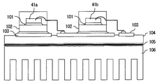
図5は、本実施の形態とは異なる、パワー素子ユニットにおけるパワー素子の搭載例を示す図である。上アーム46を構成するスイッチング素子41aと下アーム47を構成するスイッチング素子41bは、半田101、ヒートスプレッダ102を介して金属基板103に接続され、さらに絶縁樹脂104、放熱グリス105を介してヒートシンク106に接続されている。2つのスイッチング素子41a、41bの金属基板103は、それぞれドレイン端子を兼ねており、それぞれ異なる電位を有するので絶縁樹脂104により絶縁されている。パワー素子であるスイッチング素子41a、41bの熱は絶縁樹脂104を介してヒートシンク106に伝熱され、空気中に放熱される。パワー素子の電熱経路は発熱体であるチップ41a、41b、外部との接続体となるヒートスプレッダ102、それらを接続する半田101であり、それぞれの熱伝導率は0.0254W/m・K、0.0293W/m・K、0.0165W/m・Kである。一方、絶縁樹脂104の熱伝導率は0.07〜0.09W/m・Kであり、絶縁物が伝熱経路に介在することで放熱性を大きく損なっている。
FIG. 5 is a diagram showing a mounting example of a power element in a power element unit, which is different from the present embodiment. The switching
本実施の形態では、前記図5で説明したように、上アーム46と下アーム47のパワー素子(スイッチング素子)41を並べて基板上に配置し、それぞれを絶縁しておいてから当該絶縁物を介して導電性材料のヒートシンクを搭載するのでなく、上アーム46と下アーム47のパワー素子(スイッチング素子)41にそれぞれ別のヒートシンク(内側ヒートシンク50、外側ヒートシンク60)を直接接続している。そして、別々のヒートシンク(内側ヒートシンク50、外側ヒートシンク60)間を絶縁しており、パワー素子(スイッチング素子)41とヒートシンク50、60の間に絶縁物を介在しなくてよい。すなわち、パワー素子(スイッチング素子)41のベース部(ドレイン)とヒートシンク50、51は同電位であるので絶縁物を介さず直接半田づけ等により接続することができる。このように、熱抵抗の大きな絶縁物を介する必要がないので、熱抵抗を低下することができ放熱性を向上することができる。
In the present embodiment, as described with reference to FIG. 5, the power elements (switching elements) 41 of the
また、前記図5では、上アーム46と下アーム47のパワー素子(スイッチング素子)41の電気的接続のために、配線を必要としたが、本実施の形態によれば、ヒートシンク50、51が配線を兼ねている。例えば、U相の上アーム46は4つのスイッチング素子41を搭載しているが、これら4つのドレイン端子を並列接続するのに銅線などの配線を用いるのではなく、4つのスイッチング素子41をヒートシンクに直接接続することで、並列的な電気的接続が成立している。下アーム47のパワー素子(スイッチング素子)41のドレイン端子の並列接続も同様である。また、V相、W相のパワー素子(スイッチング素子)についても同様である。すなわち、ヒートシンク50、51が配線を兼ねることで銅線等の配線を少なくすることができ、パワー素子ユニット自体のサイズを小さくすることができる。
In FIG. 5, wiring is required for the electrical connection between the power elements (switching elements) 41 of the
また、回転子15の軸方向の両端面にはファン17が搭載されており、回転子15の回転により、カバー30に設けた通風孔30aから冷却風をカバー30の内部に吸入し、パワー素子ユニット4を構成するパワー素子41、内側ヒートシンク50、外側ヒートシンク51、制御回路44、結線板55を冷却する。さらに、リヤブラケット11の通風孔11aから回転電機10の本体に軸方向に冷却風を通すことにより、装置全体の冷却性を高めることができる。
また、内側ヒートシンク50、外側ヒートシンク51にはそれぞれ放熱フィンを設置している。さらに、ヒートシンク50、51の放熱フィンの面積の広い側の面を、概略回転子15の軸方向に向いて配置している。このようなヒートシンクのフィン構造であれば、フィンの放熱面が風の流れに沿う向きとなるので、圧力損失を増加させにくく、冷却のための風量を確保するのに好都合である。また、ヒートシンク50、51に搭載されるパワー素子41は回転子15の径方向に並列に配設されているので、パワー素子41が接続されている面が効率よく冷却される。
Further, the
さらに、耐熱性の低い制御回路44を、パワー素子ユニット4よりも軸方向に上流の外周側に配置している。回転子15のファン17により発生する風の流れは外周側から吸入されるので、制御回路44を冷却風の上流に配置することにより、より低温の流体で制御回路44を冷却することができ、制御回路44の冷却性を高めることができる。
Further, the
また、図3に示すように、U相部位60、V相部位70、W相部位80を構成する各パワー素子41、内側ヒートシンク50、外側ヒートシンク51は、それぞれ略90度の角度を有するように配置されており、全体としてコの字状を形成している。そして、U相部位60、V相部位70、W相部位80でない(パワー素子ユニット4の配置されていない)1辺には回転子15の界磁巻線14に給電するためのブラシユニット19が配置されている。このように、パワー素子ユニット4とブラシユニット19を同じ平面に位相を分け合って配置することで、装置全体としての軸長を短くすることができる。
Further, as shown in FIG. 3, the
なお、前記では、回転子15に界磁巻線14、ブラシホルダ19を配設した回転電機10について説明したが、界磁巻線14、ブラシホルダ19を備えていない回転電機10に適用することも可能である。また、前記U相部位60、V相部位70、W相部位80の配設されていない1辺に、ブラシホルダ19の代わりに制御回路44を搭載した基板を配置してもよい。
In the above description, the rotary
前記において、内側ヒートシンク50は、U相部位60、V相部位70、W相部位80の3部品から構成されるものを示したが、これを連結して1部品とし、U相、V相、W相の各上アーム46のパワー素子(スイッチング素子)41を同一のヒートシンクに搭載することにより、配線組立をさらに合理化することができる。
In the above, the
また、本実施の形態による回転電機を、電源電圧が100V未満である回転電機や、車載用モータジェネレータに適用すると、特に放熱性の向上や、装置の小型化の点で効果を発揮する。 Further, when the rotating electrical machine according to the present embodiment is applied to a rotating electrical machine having a power supply voltage of less than 100 V or an in-vehicle motor generator, the effects are particularly exhibited in terms of improving heat dissipation and reducing the size of the apparatus.
実施の形態2.
前記実施の形態1では、上アームおよび下アームのスイッチング素子のドレイン端子が絶縁物を介することなく別々のヒートシンクに接続されている例について説明したが、本実施の形態では、スイッチング回路部の上アームまたは下アームのスイッチング素子のいずれかのドレイン端子が絶縁物を介することなくヒートシンクに接続されている例について説明する。
Embodiment 2. FIG.
In the first embodiment, the example in which the drain terminals of the switching elements of the upper arm and the lower arm are connected to different heat sinks without using an insulator has been described. An example in which the drain terminal of either the switching element of the arm or the lower arm is connected to the heat sink without an insulator will be described.
図6は、この発明の実施の形態2による回転電機のパワー素子ユニットの配置例を示す平面図であり、図1のA−A線から観た平面図である。なお、図1で示したブラシホルダ19および回転位置検出センサ22は省略している。
6 is a plan view showing an arrangement example of power element units of a rotary electric machine according to Embodiment 2 of the present invention, and is a plan view seen from the line AA of FIG. Note that the
図において、パワー素子ユニット4(インバータモジュール40)を構成するパワー素子(スイッチング素子)41a、41bは、U、V、Wの3相の部位(U相部位60、V相部位70、W相部位80)に分かれて配置されている。各部位には、それぞれ1個のヒートシンク52が設置されている。そして、各ヒートシンク52にはディスクリートタイプのパワー素子であるスイッチング素子41a、41bがそれぞれ並列に2個ずつ接続されている。
In the figure, power elements (switching elements) 41a and 41b that constitute the power element unit 4 (inverter module 40) are U, V, and W three-phase parts (
例えば、U相部位60について説明すると、当該ヒートシンク52には、U相に対応する上アーム46のスイッチング素子41a(図示白抜き)が2個接続されている。また、当該ヒートシンク52には、U相に対応する下アーム47のスイッチング素子41b(図示斜線)が2個接続されている。なお、各スイッチング素子41a、41bはそれぞれ回路的に並列に接続している。
For example, the
図7はこの発明の実施の形態2による回転電機のパワー素子ユニットの搭載例を示す図である。上アーム46を構成するスイッチング素子41aのベース板(ドレイン端子)は半田101、ヒートスプレッダ102を介してヒートシンク52に直接接続している。ヒートシンク52はバッテリ5の正極側電位に接続されている。下アーム47を構成するスイッチング素子41bは、半田101、ヒートスプレッダ102を介して金属基板103に接続され、さらに絶縁樹脂104、放熱グリス105を介してヒートシンク52に接続されている。
FIG. 7 is a diagram showing an example of mounting a power element unit of a rotating electrical machine according to Embodiment 2 of the present invention. The base plate (drain terminal) of the switching
以上のように、本実施の形態によれば、パワー素子であるスイッチング素子とヒートシンクの間の絶縁層が一部不要となるので熱伝導率を向上することができる。その結果、スイッチング素子の放熱量が向上し、パワー素子ユニットの冷却性が向上する。 As described above, according to the present embodiment, a part of the insulating layer between the switching element, which is a power element, and the heat sink becomes unnecessary, so that the thermal conductivity can be improved. As a result, the heat dissipation amount of the switching element is improved, and the cooling performance of the power element unit is improved.
また、ヒートシンクを配線として使用することができるので、配線部品の部品点数を少なくでき、また、配線基板自体も小型化することができ、装置全体の小型化が図れる。 Further, since the heat sink can be used as the wiring, the number of wiring parts can be reduced, and the wiring board itself can be reduced in size, so that the entire apparatus can be reduced in size.
また、パワー素子ユニット部の小型化により、風路が確保され有効な冷却が実施されるので全体の冷却性を確保できる。また、制御回路等と一体にすることができ、接続のケーブル機器が省略できるので、システムとして安価にすることができ、また、故障確率を低減できるという効果がある。 Moreover, since the air passage is secured and effective cooling is performed by downsizing the power element unit portion, the entire cooling performance can be secured. In addition, since it can be integrated with a control circuit and the like and the connected cable device can be omitted, the system can be made inexpensive and the failure probability can be reduced.
4 パワー回路ユニット、10 回転電機、14 界磁巻線、15 回転子、
16 固定子、16a 電機子巻線、17 ファン、
41 スイッチング素子(パワー素子)、44 制御回路、46 上アーム、
47 下アーム、50 内側ヒートシンク、51 外側ヒートシンク、
52 ヒートシンク、60 U相部位、70 V相部位、80 W相部位。
4 power circuit units, 10 rotating electrical machines, 14 field windings, 15 rotors,
16 Stator, 16a Armature winding, 17 Fan,
41 switching element (power element), 44 control circuit, 46 upper arm,
47 lower arm, 50 inner heat sink, 51 outer heat sink,
52 heat sink, 60 U phase site, 70 V phase site, 80 W phase site.
Claims (17)
前記回転電機部に一体的または近接して設けられるとともに、少なくとも上アームおよび下アームを構成する一対のスイッチング素子を備えて前記回転電機部のスイッチング制御を行うスイッチング回路部とを備え、
前記スイッチング回路部の上アームおよび下アームのスイッチング素子の両方のドレイン端子が絶縁物を介することなく別々のヒートシンクに接続されていることを特徴とする回転電機。 A rotating electrical machine unit including a rotor disposed rotatably and a stator having an armature winding disposed so as to surround the rotor;
A switching circuit unit that is provided integrally or in proximity to the rotating electrical machine unit and includes a pair of switching elements that constitute at least an upper arm and a lower arm, and performs switching control of the rotating electrical machine unit,
A rotating electric machine characterized in that drain terminals of both switching elements of the switching circuit section are connected to different heat sinks without an insulator.
前記回転電機部に一体的または近接して設けられるとともに、少なくとも上アームおよび下アームを構成する一対のスイッチング素子を備えて前記回転電機部のスイッチング制御を行うスイッチング回路部とを備え、
前記スイッチング回路部の上アームまたは下アームのスイッチング素子のいずれかのドレイン端子が絶縁物を介することなくヒートシンクに接続されていることを特徴とする回転電機。 A rotating electrical machine unit including a rotor disposed rotatably and a stator having an armature winding disposed so as to surround the rotor;
A switching circuit unit that is provided integrally or in proximity to the rotating electrical machine unit and includes a pair of switching elements that constitute at least an upper arm and a lower arm, and performs switching control of the rotating electrical machine unit,
A rotating electrical machine, wherein a drain terminal of either the switching element of the upper or lower arm of the switching circuit portion is connected to a heat sink without an insulator.
Priority Applications (1)
| Application Number | Priority Date | Filing Date | Title |
|---|---|---|---|
| JP2004164057A JP2005348494A (en) | 2004-06-02 | 2004-06-02 | Dynamo-electric machine |
Applications Claiming Priority (1)
| Application Number | Priority Date | Filing Date | Title |
|---|---|---|---|
| JP2004164057A JP2005348494A (en) | 2004-06-02 | 2004-06-02 | Dynamo-electric machine |
Publications (1)
| Publication Number | Publication Date |
|---|---|
| JP2005348494A true JP2005348494A (en) | 2005-12-15 |
Family
ID=35500363
Family Applications (1)
| Application Number | Title | Priority Date | Filing Date |
|---|---|---|---|
| JP2004164057A Pending JP2005348494A (en) | 2004-06-02 | 2004-06-02 | Dynamo-electric machine |
Country Status (1)
| Country | Link |
|---|---|
| JP (1) | JP2005348494A (en) |
Cited By (6)
| Publication number | Priority date | Publication date | Assignee | Title |
|---|---|---|---|---|
| JP2007037280A (en) * | 2005-07-27 | 2007-02-08 | Mitsubishi Electric Corp | Rotary electric machine with integrated inverter |
| JP2007189867A (en) * | 2006-01-16 | 2007-07-26 | Mitsubishi Electric Corp | Rotary electric machine integrating controller and method of manufacturing same |
| JP2007336638A (en) * | 2006-06-13 | 2007-12-27 | Mitsubishi Electric Corp | Controller and controller-integrated rotary electric machine |
| EP1993192A1 (en) * | 2006-02-21 | 2008-11-19 | Mitsubishi Electric Corporation | Rotating electrical machine with built-in controller |
| US7589481B2 (en) | 2006-01-16 | 2009-09-15 | Mitsubishi Electric Corporation | Control device integrated dynamo-electric machine |
| JP2009284563A (en) * | 2008-05-19 | 2009-12-03 | Mitsubishi Electric Corp | Rotary electric machine integrated with control device |
-
2004
- 2004-06-02 JP JP2004164057A patent/JP2005348494A/en active Pending
Cited By (10)
| Publication number | Priority date | Publication date | Assignee | Title |
|---|---|---|---|---|
| JP2007037280A (en) * | 2005-07-27 | 2007-02-08 | Mitsubishi Electric Corp | Rotary electric machine with integrated inverter |
| JP2007189867A (en) * | 2006-01-16 | 2007-07-26 | Mitsubishi Electric Corp | Rotary electric machine integrating controller and method of manufacturing same |
| US7589481B2 (en) | 2006-01-16 | 2009-09-15 | Mitsubishi Electric Corporation | Control device integrated dynamo-electric machine |
| EP1993192A1 (en) * | 2006-02-21 | 2008-11-19 | Mitsubishi Electric Corporation | Rotating electrical machine with built-in controller |
| US8198763B2 (en) | 2006-02-21 | 2012-06-12 | Mitsubishi Electric Corporation | Controller-integrated electric rotating machine with a shifted control circuit |
| EP1993192A4 (en) * | 2006-02-21 | 2014-04-09 | Mitsubishi Electric Corp | Rotating electrical machine with built-in controller |
| US8704415B2 (en) | 2006-02-21 | 2014-04-22 | Mitsubishi Electric Corporation | Controller-integrated electric rotating machine with a shifted control circuit |
| JP2007336638A (en) * | 2006-06-13 | 2007-12-27 | Mitsubishi Electric Corp | Controller and controller-integrated rotary electric machine |
| JP2009284563A (en) * | 2008-05-19 | 2009-12-03 | Mitsubishi Electric Corp | Rotary electric machine integrated with control device |
| JP4493700B2 (en) * | 2008-05-19 | 2010-06-30 | 三菱電機株式会社 | Controller-integrated rotating electrical machine |
Similar Documents
| Publication | Publication Date | Title |
|---|---|---|
| JP4583191B2 (en) | Rotating electric machine | |
| JP4275614B2 (en) | Rotating electric machine for vehicles | |
| US7358699B2 (en) | Rotating electric machine with built-in control device | |
| US8198763B2 (en) | Controller-integrated electric rotating machine with a shifted control circuit | |
| JP4279810B2 (en) | Rotating electric machine for vehicles | |
| JP6475249B2 (en) | Protective cover for automotive rotating electrical machine | |
| JP2007189865A (en) | Rotary electric machine integrated with control unit | |
| JP6621491B2 (en) | Rotating electric machine | |
| JP2016537959A (en) | Electronic assembly for automotive rotating electrical machine | |
| JP4374312B2 (en) | Assembly method of semiconductor switching element and heat sink in in-vehicle rotating electrical machine and in-vehicle rotating electrical machine | |
| JP2004312852A (en) | Rotary electric machine for vehicle | |
| JP6872842B2 (en) | Electronic assembly for rotating electromachines for motor vehicles | |
| JP4889517B2 (en) | Rotating electrical machine equipment | |
| JP2005348494A (en) | Dynamo-electric machine | |
| JP6009609B1 (en) | Controller-integrated rotating electrical machine | |
| JP7166408B1 (en) | Rotating electric machine | |
| JP4078970B2 (en) | Inverter with multi-phase AC rotating electrical machine | |
| JP6934985B1 (en) | Rotating machine | |
| JP2004208467A (en) | Inverter to be mounted on polyphase ac rotary electric machine | |
| JP2005245150A (en) | Rotary electric machine for vehicle |
Legal Events
| Date | Code | Title | Description |
|---|---|---|---|
| A621 | Written request for application examination |
Free format text: JAPANESE INTERMEDIATE CODE: A621 Effective date: 20061002 |
|
| A977 | Report on retrieval |
Free format text: JAPANESE INTERMEDIATE CODE: A971007 Effective date: 20090605 |
|
| A131 | Notification of reasons for refusal |
Free format text: JAPANESE INTERMEDIATE CODE: A131 Effective date: 20090616 |
|
| A02 | Decision of refusal |
Free format text: JAPANESE INTERMEDIATE CODE: A02 Effective date: 20091020 |