JP2005338533A - Image forming apparatus - Google Patents
Image forming apparatus Download PDFInfo
- Publication number
- JP2005338533A JP2005338533A JP2004158704A JP2004158704A JP2005338533A JP 2005338533 A JP2005338533 A JP 2005338533A JP 2004158704 A JP2004158704 A JP 2004158704A JP 2004158704 A JP2004158704 A JP 2004158704A JP 2005338533 A JP2005338533 A JP 2005338533A
- Authority
- JP
- Japan
- Prior art keywords
- counter
- unit
- use mode
- setting
- image forming
- Prior art date
- Legal status (The legal status is an assumption and is not a legal conclusion. Google has not performed a legal analysis and makes no representation as to the accuracy of the status listed.)
- Pending
Links
- 238000001514 detection method Methods 0.000 claims abstract description 16
- 238000012545 processing Methods 0.000 claims description 11
- 238000013500 data storage Methods 0.000 abstract description 14
- 230000002093 peripheral effect Effects 0.000 description 19
- 238000012546 transfer Methods 0.000 description 11
- 238000010586 diagram Methods 0.000 description 6
- 230000032258 transport Effects 0.000 description 6
- 238000000034 method Methods 0.000 description 3
- 238000012805 post-processing Methods 0.000 description 3
- 239000002131 composite material Substances 0.000 description 2
- 230000006870 function Effects 0.000 description 2
- 238000012423 maintenance Methods 0.000 description 2
- 238000006243 chemical reaction Methods 0.000 description 1
- 238000011161 development Methods 0.000 description 1
- 238000007726 management method Methods 0.000 description 1
Images


Abstract
Description
本発明は、記録紙への印刷枚数をカウントするカウンタを備える画像形成装置に関するものである。 The present invention relates to an image forming apparatus including a counter that counts the number of prints on a recording sheet.
複写機等の画像形成装置では、装置本体に対して着脱可能であり、記録紙の印刷枚数をカウントするカウンタが使用されることがある。カウンタを使用する場合、画像形成装置をカウンタ使用モードに設定する必要がある。通常、この設定は、サービスマンのみがログインすることができるメンテナンスモードにて行われる。そして、カウンタ使用モードが設定された場合、カウンタが装置本体から取り外されると、画像形成装置は、印刷動作を禁止する。 In an image forming apparatus such as a copying machine, a counter that can be attached to and detached from the apparatus main body and counts the number of recording sheets to be printed may be used. When using the counter, it is necessary to set the image forming apparatus to the counter use mode. Normally, this setting is performed in a maintenance mode in which only a service person can log in. When the counter use mode is set, when the counter is removed from the apparatus main body, the image forming apparatus prohibits the printing operation.
その他、本発明に関連する技術として、カウンタの通電電流を検出することによって、カウンタが装着されていることを検出するもの(特許文献1)、外部カウンタの離脱が検知されると、用紙の給紙を停止させ、複写停止後に外部カウンタの装着が検知されると、内部カウンタの内容を用いて外部カウンタの内容を補正するもの(特許文献2)、複写開始後給送動作開始前にキーカウンタを除去したとき、給送手段の動作を阻止するもの(特許文献3)、及びプラグインカウンタの装着状態によって複写動作の開始が可能となる複写機にて、給紙手段の動作の前にプラグインカウンタが非装着状態となったとき、給紙手段の動作を阻止するもの(特許文献4)が開示されている。
しかしながら、従来の画像形成装置では、メンテナンスモードにログインしてカウンタ使用モードを解除すれば、カウンタを装置本体から取り外しても、画像形成装置に対して印刷動作を行なわせることが可能であった。この解除操作は、操作パネルを使った簡便なものであり、しかも、サービスマンに対して公開されているため、ユーザは、この解除操作を知ることが可能であり、一旦、解除操作を把握すれば、カウンタ使用モードが設定された状態において、装置本体からカウンタを取り外し、画像形成装置に対して印刷動作を行なわせるというようなカウンタの不正使用を容易に行なうことが可能であった。 However, in the conventional image forming apparatus, if the counter use mode is canceled by logging in to the maintenance mode, it is possible to cause the image forming apparatus to perform a printing operation even if the counter is detached from the apparatus main body. This release operation is a simple operation using the operation panel, and since it is open to the service personnel, the user can know the release operation. For example, in a state where the counter use mode is set, it is possible to easily perform illegal use of the counter such as removing the counter from the apparatus main body and causing the image forming apparatus to perform a printing operation.
本発明の目的は、カウンタの不正使用を防止する画像形成装置を提供することである。 An object of the present invention is to provide an image forming apparatus that prevents unauthorized use of a counter.
本発明にかかる画像形成装置は、装置本体に対して着脱可能であり、印刷枚数をカウントするカウンタを備える画像形成装置であって、オペレータからの操作指令を受け付ける操作手段と、装置本体をカウンタ使用モードに設定する設定手段と、前記カウンタが装置本体に対して接続されているか否かを検出する検出する検出手段と、前記設定手段によりカウンタ使用モードに設定がされ、かつ、前記検出手段により前記カウンタが装置本体に接続されていないことが検出された場合、印刷動作を禁止する禁止手段とを備え、前記設定手段は、装置本体を一度カウンタ使用モードに設定すると、前記操作手段を用いて前記カウンタ使用モードを解除する操作指令が入力されても当該設定を解除しないことを特徴とする。 An image forming apparatus according to the present invention is an image forming apparatus that is detachable from the apparatus main body and includes a counter that counts the number of printed sheets, and includes an operation unit that receives an operation command from an operator and a counter that uses the apparatus main body. A setting means for setting the mode, a detection means for detecting whether or not the counter is connected to the apparatus main body, a counter use mode is set by the setting means, and the detection means When it is detected that the counter is not connected to the apparatus main body, the setting means includes a prohibiting means for prohibiting a printing operation, and once the apparatus main body is set to the counter use mode, the operation means is used to set the counter The setting is not canceled even when an operation command for canceling the counter use mode is input.
また、前記設定手段は、カウンタ使用モードが設定されていない状態において、前記検出手段によりカウンタの接続が検出された時、装置本体をカウンタ使用モードに設定することが好ましい。 The setting means preferably sets the apparatus main body to the counter use mode when the connection of the counter is detected by the detection means in a state where the counter use mode is not set.
また、種々の設定を行なうために用いられ、装置本体に対して着脱可能な外部コンソールを更に備え、前記設定手段は、外部コンソールからカウンタ使用モードの設定を解除する操作指令が入力された場合、当該設定を解除することが好ましい。 In addition, it further includes an external console that can be used to make various settings and can be attached to and detached from the apparatus main body, and when the operation command for canceling the setting of the counter use mode is input from the external console, It is preferable to cancel the setting.
また、前記カウンタは、電磁式のカウンタであり、前記検知手段は、前記カウンタのコイルの一端に接続された第1の電源部と、第1及び第2のポートを備え、前記カウンタを動作させるためのカウント信号を前記第1のポートから出力する中央演算処理装置と、前記カウント信号を前記コイルの他端に導くカウンタ信号ラインと、前記第2のポートに前記中央演算処理装置の所定の電圧を供給する第2の電源部と、前記コイルの他端及び前記第2のポート間に接続され、前記カウンタの接続の有無に応じて、前記第2の電源部の駆動電圧を第1のレベル、又は前記第1のレベルとは異なる第2のレベルの電圧として、前記第2のポートに出力する電圧変更部とを備え、前記中央演算処理装置は、第2のポートに対して前記第1のレベル、又は前記第2のレベルの電圧が入力されるかに応じて前記カウンタが接続されているか否かを判定することが好ましい。 The counter is an electromagnetic counter, and the detection means includes a first power supply unit connected to one end of a coil of the counter, and first and second ports, and operates the counter. A central processing unit for outputting a count signal for output from the first port, a counter signal line for guiding the count signal to the other end of the coil, and a predetermined voltage of the central processing unit for the second port Is connected between the other end of the coil and the second port, and the driving voltage of the second power supply unit is set to the first level according to whether the counter is connected or not. Or a voltage changing unit that outputs to the second port as a second level voltage different from the first level, wherein the central processing unit is configured to output the first port with respect to the second port. Level, or It is preferable to determine whether the counter is connected depending on whether the voltage of the second level is inputted.
請求項1記載の発明によれば、カウンタ使用モードが設定された状態において、カウンタが装置本体に接続されていないことが検出された場合、印刷動作が禁止され、しかも、一度カウンタ使用モードが設定されると、この設定は、操作手段を用いてカウンタ使用モードの設定を解除する操作指令を入力しても解除されないため、カウンタ使用モードの設定状態において、カウンタを装置本体から取り外し、操作手段を用いてカウンタ使用モードを解除し、画像形成装置に対し印刷動作を行なわせるようなカウンタの不正使用を防止することができる。 According to the first aspect of the present invention, when it is detected that the counter is not connected to the apparatus main body in the state where the counter use mode is set, the printing operation is prohibited, and the counter use mode is once set. Then, since this setting is not canceled even if an operation command for canceling the setting of the counter use mode is input using the operation means, the counter is removed from the apparatus main body in the setting state of the counter use mode, and the operation means is removed. Thus, the counter use mode can be canceled to prevent unauthorized use of the counter that causes the image forming apparatus to perform a printing operation.
請求項2記載の発明によれば、カウンタ使用モードが設定されていない状態において、カウンタが接続されると、自動的にカウンタ使用モードに設定されるため、カウンタ使用モードの設定作業を簡略化することができる。 According to the second aspect of the present invention, when the counter is connected in the state where the counter use mode is not set, the counter use mode is automatically set, so that the setting operation of the counter use mode is simplified. be able to.
請求項3記載の発明によれば、外部コンソールを用いた場合のみ、カウンタ使用モードの設定を解除することができるため、外部コンソールの存在を知らない一般ユーザに対するカウンタ使用モードの設定解除を困難としつつ、カウンタ使用モードの設定を解除することができる。 According to the third aspect of the invention, since the counter use mode setting can be canceled only when the external console is used, it is difficult to cancel the counter use mode setting for general users who do not know the existence of the external console. Meanwhile, the setting of the counter use mode can be canceled.
請求項4記載の発明によれば、中央処理装置の第2のポートには、カウンタの接続の有無に応じて第1のレベル又は第2のレベルの電圧が入力され、中央処理装置は、第2のポートに入力された電圧のレベルを基に、カウンタの接続の有無を判定しているため、カウンタの接続の有無を高精度に検出することができる。 According to the fourth aspect of the present invention, the first level or the second level voltage is input to the second port of the central processing unit according to whether the counter is connected or not. Since whether or not the counter is connected is determined based on the level of the voltage input to the second port, it is possible to detect whether or not the counter is connected with high accuracy.
以下、図面を参照しつつ、本発明の実施の形態について説明する。図1は、本発明に係る画像形成装置をデジタル複合機に適用したときの機械的構成を主に示す側面概略図である。デジタル複合機は、本体部200と、本体部200の左側に配設された用紙後処理部300と、ユーザが種々の操作指令等を入力するための操作部400と、本体部200の上部に配設された原稿読み取り部500と、原稿読み取り部500の上方に配設された原稿給送部600とから構成される。
Hereinafter, embodiments of the present invention will be described with reference to the drawings. FIG. 1 is a schematic side view mainly showing a mechanical configuration when the image forming apparatus according to the present invention is applied to a digital multi-function peripheral. The digital multi-function peripheral includes a
操作部400は、操作パネル401、スタートキー402及びテンキー403等を備える。操作パネル401は、種々の操作画面を表示するとともに、ユーザが種々の操作指令を入力するための種々の操作ボタン等を表示する。スタートキー402は、ユーザが印刷実行指令等を入力するために用いられ、テンキー403は、印刷部数等を入力するために用いられる。
The
原稿給送部600は、原稿載置部601、原稿排出部602、給紙ローラ603及び原稿搬送部604等を備え、原稿読み取り部500は、スキャナ501等を備える。給紙ローラ603は、原稿載置部601にセットされた原稿を繰り出し、原稿搬送部604は、繰り出される原稿を1枚ずつ順にスキャナ501上に搬送する。スキャナ501は搬送される原稿を順次読み取り、読み取られた原稿は原稿排出部602に排出される。
The
本体部200は、複数の給紙カセット201、複数の給紙ローラ202、転写ローラ203、中間転写体ローラ204、感光体ドラム205、露光装置206、イエロー、マゼンタ、シアン、ブラックの各色用の現像装置207Y,207M,207C,207K、定着ローラ208、排出口209、及び排出トレイ210等を備える。
The
感光体ドラム205は、矢印方向に回転しながら帯電装置(図示省略)によって一様に帯電される。露光装置206は、原稿読み取り部500において読み取られた原稿の画像データに基づいて生成された変調信号をレーザ光に変換して出力し、感光体ドラム205に各色別に静電潜像を形成する。現像装置207Y,207M,207C,207Kは、各色の現像剤を感光体ドラム205に供給して各色別のトナー像を形成する。
The
中間転写体ローラ204は、感光体ドラム205から各色のトナー像が転写され、中間転写体ローラ204上にカラーのトナー像が形成される。
The
一方、給紙ローラ202は、記録紙が収納された給紙カセット201から記録紙を引き出し、転写ローラ203まで給送する。転写ローラ203は、搬送された記録紙に中間転写体ローラ204上のトナー像を転写させ、定着ローラ208は、転写されたトナー像を加熱して記録紙に定着させる。その後、記録紙は、本体部200の排出口209から用紙後処理部300に搬入される。また、記録紙は、必要に応じて排出トレイ210へも排出される。
On the other hand, the
用紙後処理部300は、搬入口301、記録紙搬送部302、搬出口303及びスタックトレイ304等を備える。記録紙搬送部302は、排出口209から搬入口301に搬入された記録紙を順次搬送し、最終的に搬出口303からスタックトレイ304へ記録紙を排出する。スタックトレイ304は、搬出口303から搬出された記録紙の集積枚数に応じて矢印方向に上下動可能に構成されている。
The
図2は、図1に示すデジタル複合装置の電気的構成を示すブロック図である。本デジタル複合機は、原稿データ取得部1、ハードディスクドライブ(HDD)2、操作部3、印刷部4、カウンタ5、プリンタコントローラ6、FAX部7、制御部8、及び外部コンソール9を備えている。プリンタコントローラ6には、10BASE−T、100BASE―TX等のLANケーブルCを介して、1又は複数のパーソナルコンピュータ(PC)10が接続されている。FAX部7は、公衆電話網と接続されている。外部コンソール9は、RS−232Cケーブル等を介して、制御部8に接続されている。
FIG. 2 is a block diagram showing an electrical configuration of the digital composite apparatus shown in FIG. The digital multi-function peripheral includes a document
原稿データ取得部1は、図1に示す原稿読み取り部500及び原稿給送部600等から構成され、原稿載置部601に載置された原稿の画像をスキャナ501で読み取り、得られた原稿データをアナログデジタル変換し、制御部8に出力する。
The document
HDD2は、制御部8の制御の下、原稿データ取得部1によって取得された原稿データ、プリンタコントローラ6によって受信されたPC10からの印刷データ、FAX部7によって受信されたファクシミリデータを記憶する。
The
操作部3は、操作パネル401、スタートキー402及びテンキー403から構成され、ユーザが、種々の操作指令を入力する際に用いられる。
The
印刷部4は、検出部41、モードデータ記憶部42、LSU(laser scan unit)43、及びCPU44を備えている。検出部41は、カウンタ5の接続の有無に応じたレベルの電圧信号を生成し、CPU44に出力する。モードデータ記憶部42は、不揮発性の記憶装置から構成され、カウンタ使用モードが設定されていることを示すカウンタ使用データを記憶する。ここで、カウンタ使用モードとは、本デジタル複合機にカウンタ5を接続し、このカウンタ5に対し印刷枚数をカウントさせるモードである。LSU43は、図1に示す転写ローラ203、中間転写体ローラ204、感光体ドラム205、露光装置206、現像装置207Y,207M,207C,207K、及び定着ローラ208等から構成され、制御部8の制御の下、HDD2に記憶された原稿データ、印刷データ、及びファクシミリデータを記録紙に印刷する。
The
CPU44は、検出部41から出力される電圧信号のレベルから、カウンタ5が接続されているか否かを判定する。また、CPU44は、カウンタ5が接続されていると判定し、かつ、モードデータ記憶部42にカウンタ設定データが記憶されていない場合、モードデータ記憶部42にカウンタ使用データを記憶させ、本デジタル複合機をカウンタ使用モードに設定する。これにより、カウンタ5を接続するだけで、自動的にカウンタ使用モードが設定されることとなる。
The
また、CPU44は、カウンタ使用モードが設定されていない場合において、ユーザが操作部3を介して、カウンタ使用モードを設定するための操作指令を入力し、制御部8がその操作指令を受け付けた場合、モードデータ記憶部42にカウンタ設定データを記憶させる。一方、CPU44は、カウンタ使用モードが設定されている場合において、ユーザにより、操作部3を介してカウンタ使用モードの設定を解除する操作指令が入力され、制御部8がその操作指令を受け付けた場合、モードデータ記憶部42からカウンタ設定データを消去することなく、カウンタ使用モードをそのまま維持する。したがって、一度、カウンタ使用モードが設定されると、ユーザは、操作部3を操作しても、カウンタ使用モードの設定を解除することができない。
Further, when the counter use mode is not set, the
一方、制御部8に外部コンソール9が接続され、外部コンソール9を介してカウンタ使用モードの設定を解除する操作指令が入力され、制御部8がその操作指令を受け付けた場合、CPU44は、モードデータ記憶部42からカウンタ設定データを消去し、カウンタ使用モードの設定を解除する。
On the other hand, when the external console 9 is connected to the
さらに、CPU44は、モードデータ記憶部42にカウンタ設定データが記憶され、かつ、カウンタ5が接続されていないと判定した場合、LSU43による印刷動作を禁止させる。一方、CPU44は、モードデータ記憶部42にカウンタ設定データが記憶され、かつ、カウンタ5が接続されていると判定した場合、LSU43による印刷動作を行なわせる。さらに、CPU44は、LSU43が1枚の記録紙に印刷を行なう毎に、カウンタ5のカウンタ値を1カウントアップさせる。
Further, when the
カウンタ5は、デジタル複合機に対して着脱可能な電磁式のカウンタから構成されている。 The counter 5 includes an electromagnetic counter that can be attached to and detached from the digital multi-function peripheral.
プリンタコントローラ6は、PC10から出力された印刷データを受信し、フォント変換処理等を施し、制御部8に出力する。そして、制御部8により、印刷データはHDD2に記憶される。FAX部7は、モデム、NCU(network control unit)等から構成され、電話回線網からのファクシミリデータを受信し、制御部8に出力する。そして、制御部8により、ファクシミリデータはHDD2に記憶される。
The
制御部8は、CPU(central processing unit)、ROM(read only memory)、RAM(random access memory)等を備え、本デジタル複合機の制御を行い、原稿読み取り部1からの原稿データ、プリンタコントローラ6からの印刷データ、及びFAX部7からのファクシミリデータの各々に対し、所定容量データを1つのジョブとして設定し、設定したジョブを管理するジョブ管理機能、及び原稿データ、印刷データ、及びファクシミリデータに対して所定の画像処理を施し、印刷部4に出力する画像処理機能等を備えている。
The
なお、本実施形態では、CPU44及びモードデータ記憶部42が設定手段の一例に相当し、検出部41及びCPU44が検出手段の一例に相当し、CPU44が禁止手段の一例に相当し、操作部3及び制御部8が操作手段の一例に相当する。
In this embodiment, the
図3はカウンタ5の外観構成図を示し、(a)は前面図、(b)は側面図、(c)は上面図を示している。なお、(b)において左側が前面であり、(c)において上側が前面である。カウンタ5の前面中央には、矩形状の表示部51が配設され、上面及び下面にはそれぞれ2個のストッパ52が配設されている。表示部51は、側面に0から9の番号が付されたほぼ円盤状の表示板が横方向に所定個数、回転可能に配列され、所定桁の数値を表示する。
FIG. 3 is an external configuration diagram of the counter 5, (a) is a front view, (b) is a side view, and (c) is a top view. In (b), the left side is the front surface, and in (c), the upper side is the front surface. A
本デジタル複合機には、カウンタ5を収納するカウンタスロット(図略)が設けられ、このカウンタスロットにカウンタ5を収納すると、ストッパ52は、カウンタスロットの接触面によりカウンタ本体側に押され、カウンタスロットの接触面を付勢し、カウンタ5をカウンタスロットに固定させる。カウンタ5の奥側には、カウンタ5をデジタル複合機に電気的に接続させる雄コネクタ53が配設され、一方、カウンタスロットの底面には、雌コネクタ(図略)が配設され、カウンタ5をカウンタスロットに完全に挿入すると、雄コネクタ53と雌コネクタとが接続される。
The digital multi-function peripheral is provided with a counter slot (not shown) for storing the counter 5. When the counter 5 is stored in the counter slot, the
図4は、検出部41の回路図を示している。検出部41は、バッファ411、インバータ412、3個の抵抗R1,R2,R3、トランジスタTr、コネクタ413,414を備えている。バッファ411は、入力側がCPU44のポートaに接続され、出力側がコネクタ414に接続されている。コネクタ413,414は、上述したカウンタスロットの底面に配設された雌コネクタであり、コネクタ414は、上述した雄コネクタ53を構成するコネクタ532に接続され、コネクタ413は、雄コネクタ53を構成するコネクタ531に接続される。コネクタ413は、24Vの電圧を供給する電源と接続され、カウンタ5に対し24Vの電圧を供給する。
FIG. 4 shows a circuit diagram of the
トランジスタTrは、npnバイポーラトランジスタから構成され、コレクタには、抵抗R1を介して5Vの電源が接続されているとともに、インバータ412の入力側が接続されている。トランジスタTrのエミッタは接地され、エミッタベース間は抵抗R3が接続されている。トランジスタTrのベースは、抵抗R2を介してコネクタ414と接続されている。インバータ412の出力側はCPU44のポートbに接続されている。
The transistor Tr is composed of an npn bipolar transistor, and the collector is connected to a power supply of 5 V via a resistor R1 and to the input side of the
カウンタ5がカウンタスロットに挿入され、コネクタ413,414とコネクタ531,532とが電気的に接続されると、24Vの電源電圧が抵抗R3及びR2により分圧されてトランジスタTrのベース・エミッタ間に印加され、トランジスタTrがonされる。そして、トランジスタTrにコレクタ電流が流れ、5Vの電源電圧は抵抗R1により電圧降下を受け、インバータ412にはローレベルの電圧が入力され、ポートbにはハイレベルの電圧が入力される。これにより、CPU44は、デジタル複合機にカウンタ5が接続されていると判定する。
When the counter 5 is inserted into the counter slot and the
一方、カウンタ5がデジタル複合機から取り外されると、トランジスタTrは、ベース・エミッタ間に所定レベルの電圧が印加されず、offとされる。そのため、コレクタ電流が流れず、インバータ412には、5Vの電源電圧によるハイレベルの電圧が入力され、ポートbにはローレベルの電圧が入力される。これにより、CPU44は、デジタル複合機にカウンタ5が接続されていないと判定する。
On the other hand, when the counter 5 is removed from the digital multi-function peripheral, the transistor Tr is turned off without applying a predetermined level voltage between the base and the emitter. Therefore, the collector current does not flow, the
LSU43により、1枚の記録紙が印刷されると、CPU44は、ポートaからカウンタ5をカウントアップするためのパルス電圧を出力する。このパルス電圧はバッファ411、コネクタ414,532を介してカウンタ5に入力され、コイルLを励磁し、カウンタ5を1カウントアップさせる。なお、図4に示す回路では、抵抗R1,R2,R3=10kΩ,22kΩ,4.7kΩが好ましい。
When one recording sheet is printed by the
次に、本デジタル複合機の動作を図5に示すフローチャートに従って説明する。なお、このフローチャートは、CPU44により、例えば一定の周期で実行される。まず、ステップS1において、モードデータ記憶部42にカウンタ設定データが記憶されている場合、CPU44は、カウンタ使用モードが設定されていると判定し(ステップS1でYES)、処理をステップS2へ進める。
Next, the operation of the digital multi-function peripheral will be described with reference to the flowchart shown in FIG. This flowchart is executed by the
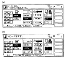
ステップS2において、CPU44のポートbにローレベルの電圧が入力されている場合、CPU44は、カウンタ5が接続されていないと判定し(ステップS2でNO)、LSU43による印刷動作を禁止する(ステップS3)。この場合、制御部8は、原稿データ取得部1の動作を禁止すると共に、操作パネル401に、図6(a)に示すようなコピー不可能であることを通知する画面を表示させ、ユーザに対し、コピー不可能であることを報知する。この状態において、ユーザは原稿載置部601に原稿をセットし、スタートキー402を押しても、印刷動作が実行されず、コピー原稿を得ることができない。
If a low level voltage is input to the port b of the
一方、ステップS2において、CPU44のポートbにハイレベルの電圧が入力されている場合、CPU44は、カウンタが接続されていると判定し(ステップS2でYES)、LSU43による印刷動作を禁止しない(ステップS4)。この場合、操作パネル401に、図6(b)に示すようなコピーが可能であることを通知する画面を表示させ、ユーザに対し、コピー可能であることを通知する。この状態において、原稿載置部601に原稿をセットし、スタートキー402を押すと、印刷動作が実行されるため、ユーザはコピー原稿を得ることができる。
On the other hand, if a high level voltage is input to the port b of the
一方、ステップS1において、CPU44は、モードデータ記憶部42にカウンタ設定データが記憶されておらず、カウンタ使用モードが設定されていないと判定し(ステップS5でYES)、かつ、カウンタ5が接続されていると判定した場合(ステップS5でYES)、モードデータ記憶部42にカウンタ設定データを記憶させ、本デジタル複合機をカウンタ使用モードに設定する(ステップS6)。これにより、ユーザは、カウンタ使用モードが設定されていない状態において、カウンタ5を接続するだけで、デジタル複合機をカウンタ使用モードに設定することができる。一方、ステップS5において、カウンタ5が接続されていないとCPU44が判定した場合(ステップS5でNO)、処理が終了される。
On the other hand, in step S1, the
以上説明したように、本デジタル複合機によれば、カウンタ使用モードが設定され、かつ、カウンタ5が接続されていない場合、印刷動作が禁止される。ここで、カウンタ使用モードは、一度設定されると、操作部3を操作しても、解除することができない。そのため、カウンタ使用モードが設定されている状態において、カウンタ5を取り外し、デジタル複合機に印刷動作を行なわせるようなカウンタの不正使用を防止することができる。
As described above, according to this digital multi-function peripheral, when the counter use mode is set and the counter 5 is not connected, the printing operation is prohibited. Here, once the counter use mode is set, it cannot be canceled even if the
一方、外部コンソール9からは、カウンタ使用モードの設定を解除することが可能であるが、外部コンソール9は、サービスマンが所有するものであり、一般ユーザはその存在を知らないため、カウンタの不正使用を防止しつつ、カウンタ使用モードの設定を解除することができる。 On the other hand, although it is possible to cancel the counter use mode setting from the external console 9, the external console 9 is owned by the service person, and the general user does not know its existence. The counter use mode setting can be canceled while preventing the use.
なお、上記実施形態では、デジタル複合機を例に挙げて説明したが、これに限定されず、複写機、コピー機等に本発明を適用してもよい。 In the above embodiment, the digital multifunction peripheral has been described as an example. However, the present invention is not limited to this, and the present invention may be applied to a copying machine, a copying machine, and the like.
1 原稿データ取得部
2 HDD
3 操作部
4 印刷部
5 カウンタ
6 プリンタコントローラ
7 FAX部
8 制御部
9 外部コンソール
41 検出部
42 モードデータ記憶部
43 LSU
44 CPU
1 Document
3
44 CPU
Claims (4)
オペレータからの操作指令を受け付ける操作手段と、
装置本体をカウンタ使用モードに設定する設定手段と、
前記カウンタが装置本体に対して接続されているか否かを検出する検出する検出手段と、
前記設定手段によりカウンタ使用モードに設定がされ、かつ、前記検出手段により前記カウンタが装置本体に接続されていないことが検出された場合、印刷動作を禁止する禁止手段とを備え、
前記設定手段は、装置本体を一度カウンタ使用モードに設定すると、前記操作手段を用いて前記カウンタ使用モードを解除する操作指令が入力されても当該設定を解除しないことを特徴とする画像形成装置。 An image forming apparatus that is detachable from the apparatus main body and includes a counter that counts the number of printed sheets,
An operation means for receiving an operation command from an operator;
Setting means for setting the device main body to the counter use mode;
Detecting means for detecting whether the counter is connected to the apparatus main body;
A prohibiting unit that prohibits a printing operation when the setting unit sets the counter use mode and the detecting unit detects that the counter is not connected to the apparatus main body;
The image forming apparatus according to claim 1, wherein the setting unit does not cancel the setting even if an operation command for canceling the counter use mode is input using the operation unit once the apparatus main body is set to the counter use mode.
前記設定手段は、外部コンソールを用いて前記カウンタ使用モードの設定を解除する操作指令が入力された場合、当該設定を解除することを特徴とする請求項1又は2記載の画像形成装置。 It is used to perform various settings, and further includes an external console that can be attached to and detached from the apparatus body,
3. The image forming apparatus according to claim 1, wherein the setting unit cancels the setting when an operation command for canceling the setting of the counter use mode is input using an external console.
前記検知手段は、
前記カウンタのコイルの一端に接続された第1の電源部と、
第1及び第2のポートを備え、前記カウンタを動作させるためのカウント信号を前記第1のポートから出力する中央演算処理装置と、
前記カウント信号を前記コイルの他端に導くカウンタ信号ラインと、
前記第2のポートに前記中央演算処理装置の所定の電圧を供給する第2の電源部と、
前記コイルの他端及び前記第2のポート間に接続され、前記カウンタの接続の有無に応じて、前記第2の電源部の駆動電圧を第1のレベル、又は前記第1のレベルとは異なる第2のレベルの電圧として、前記第2のポートに出力する電圧変更部とを備え、
前記中央演算処理装置は、第2のポートに対して前記第1のレベル、又は前記第2のレベルの電圧が入力されるかに応じて前記カウンタが接続されているか否かを判定することを特徴とする請求項1〜3のいずれかに記載の画像形成装置。 The counter is an electromagnetic counter,
The detection means includes
A first power supply connected to one end of the counter coil;
A central processing unit that includes first and second ports and outputs a count signal for operating the counter from the first port;
A counter signal line for guiding the count signal to the other end of the coil;
A second power supply for supplying a predetermined voltage of the central processing unit to the second port;
Connected between the other end of the coil and the second port, the driving voltage of the second power supply unit is different from the first level or the first level depending on whether the counter is connected or not. A voltage changing unit for outputting to the second port as a second level voltage;
The central processing unit determines whether or not the counter is connected depending on whether the first level or the second level voltage is input to the second port. The image forming apparatus according to claim 1, wherein the image forming apparatus is an image forming apparatus.
Priority Applications (1)
| Application Number | Priority Date | Filing Date | Title |
|---|---|---|---|
| JP2004158704A JP2005338533A (en) | 2004-05-28 | 2004-05-28 | Image forming apparatus |
Applications Claiming Priority (1)
| Application Number | Priority Date | Filing Date | Title |
|---|---|---|---|
| JP2004158704A JP2005338533A (en) | 2004-05-28 | 2004-05-28 | Image forming apparatus |
Publications (1)
| Publication Number | Publication Date |
|---|---|
| JP2005338533A true JP2005338533A (en) | 2005-12-08 |
Family
ID=35492180
Family Applications (1)
| Application Number | Title | Priority Date | Filing Date |
|---|---|---|---|
| JP2004158704A Pending JP2005338533A (en) | 2004-05-28 | 2004-05-28 | Image forming apparatus |
Country Status (1)
| Country | Link |
|---|---|
| JP (1) | JP2005338533A (en) |
-
2004
- 2004-05-28 JP JP2004158704A patent/JP2005338533A/en active Pending
Similar Documents
| Publication | Publication Date | Title |
|---|---|---|
| US8390841B2 (en) | Issuing a warning when a user attempts to use a device that is already being used | |
| US8683580B2 (en) | Image forming apparatus, image forming system, and authentication device | |
| JP2012049855A (en) | Image formation device and image formation system | |
| JP5291145B2 (en) | Image forming system and control method thereof | |
| US10936262B2 (en) | Image forming apparatus, a non-transitory computer-readable recording medium storing control program, and control method for alerting detection of intruder | |
| US8861026B2 (en) | Image forming apparatus | |
| JP4617981B2 (en) | Image forming system | |
| JP5232603B2 (en) | Image reading apparatus and image forming apparatus | |
| US7969614B2 (en) | Image forming apparatus capable of outputting color and monochrome images, control method thereof and computer readable recording medium | |
| JP2007049344A (en) | Image forming apparatus | |
| JP2010030149A (en) | Printing control device, printing system and printing control method | |
| JP6199810B2 (en) | Image forming apparatus | |
| JP4906748B2 (en) | Image forming apparatus | |
| JP6361521B2 (en) | Image forming apparatus | |
| CN103095952A (en) | Image Forming Apparatus | |
| JP2005338533A (en) | Image forming apparatus | |
| JP6769765B2 (en) | Image forming device, control program and control method | |
| JP5909113B2 (en) | Image forming apparatus and image forming method | |
| JP2009267590A (en) | Image forming apparatus | |
| JP2007098850A (en) | Image printing device, image printing controlling method, and control program therefor | |
| US11768725B2 (en) | Image forming apparatus with multiple cassettes and determination portion to determine a prohibited operation | |
| JP2010128334A (en) | Image forming apparatus | |
| JP2007043596A (en) | Image printer, image print control method, and control program thereof | |
| JP4390131B2 (en) | Image forming apparatus | |
| US20100134812A1 (en) | Image processing apparatus, image processing method and image forming apparatus |