JP2005337792A - Portable electronic device - Google Patents
Portable electronic device Download PDFInfo
- Publication number
- JP2005337792A JP2005337792A JP2004154643A JP2004154643A JP2005337792A JP 2005337792 A JP2005337792 A JP 2005337792A JP 2004154643 A JP2004154643 A JP 2004154643A JP 2004154643 A JP2004154643 A JP 2004154643A JP 2005337792 A JP2005337792 A JP 2005337792A
- Authority
- JP
- Japan
- Prior art keywords
- electronic device
- portable electronic
- push button
- external operation
- crown
- Prior art date
- Legal status (The legal status is an assumption and is not a legal conclusion. Google has not performed a legal analysis and makes no representation as to the accuracy of the status listed.)
- Withdrawn
Links
Images


Abstract
Description
本発明は、押ボタン等の外部操作部材を備えた携帯型電子機器に係り、特に、携帯時計
やダイビングコンピュータ等として構成する場合に好適な、外部操作部材を備えた携帯型
電子機器に関する。
The present invention relates to a portable electronic device including an external operation member such as a push button, and more particularly to a portable electronic device including an external operation member that is suitable when configured as a portable watch, a diving computer, or the like.
一般に、腕時計やダイビングコンピュータ等の携帯型電子機器においては、ケーシング
(本体)と、ケーシングを手首等に固定するためのバンドとが設けられている。ケーシン
グには、文字板や指針、或いは、液晶表示パネル等からなる表示部と、時計ムーブメント
や回路基板等を含む内部動作部と、内部動作部の動作を切り換えるための外部操作部とが
設けられる。
外部操作部としては、通常、本体に対して回転可能かつ出没可能に取付けられたリュウ
ズや、出没可能に取付けられた押ボタン等が設けられている。
リュウズを操作して回転させたり出没させたりすると、本体内のリンクや歯車等の機構
が連携して動作し、内部動作部の動作態様が切り換えられる。また、押ボタンを押圧する
と、本体内に設けられた接点が開閉し、内部回路の切り換えや動作の開始などが指示され
ることとなる。
Generally, in portable electronic devices such as a wristwatch and a diving computer, a casing (main body) and a band for fixing the casing to a wrist or the like are provided. The casing is provided with a display unit composed of a dial, a pointer, or a liquid crystal display panel, an internal operation unit including a clock movement, a circuit board, etc., and an external operation unit for switching the operation of the internal operation unit. .
As the external operation unit, a crown attached to the main body so as to be rotatable and retractable, a push button attached to be able to appear and retract, and the like are usually provided.
When the crown is operated to rotate or retract, a mechanism such as a link or a gear in the main body operates in cooperation, and the operation mode of the internal operation unit is switched. Further, when the push button is pressed, a contact provided in the main body is opened and closed, and an instruction to switch internal circuits or start an operation is given.
外部操作部を構成する部材の構造として、上述したリュウズや押ボタンの改良技術が種
々提案されている。
例えば、ネジロックリュウズのようにリュウズの出没動作を禁止し、所定位置にロック
することによって、リュウズに対する誤操作を防止するための構造が知られている。この
ネジロックリュウズは、リュウズと螺合するネジによってリュウズをロックするものであ
る。
また、バヨネット構造によって外部操作部材の位置をロックするものも知られている。
より具体的に述べると、上記のネジロックリュウズと類似した他の操作部構造として、
特許文献1に記載された押ボタンの誤動作を防止するための構造がある。特許文献1記載
の外部操作部を構成する部材の構造は、押ボタンにロック筒を螺合させ、ロック筒をねじ
込むことによって押ボタンが押圧できなくなるようにしたものである。
また、特許文献2には、腕時計の側面に沿ってスライド可能なスイッチが記載されてい
る。このスイッチは3つのスライド位置を選択することが可能であり、それぞれのスライ
ド位置において内部回路の所定の機能を活性化させる。これと同種のスライドスイッチと
しては、特許文献3に記載されたスイッチボタンも知られている
For example, a structure for preventing an erroneous operation on the crown by prohibiting the movement of the crown and locking the crown at a predetermined position like a screw lock crown is known. This screw lock crown locks the crown with a screw screwed to the crown.
Moreover, what locks the position of an external operation member with a bayonet structure is also known.
More specifically, as another operation part structure similar to the above screw lock crown,
There is a structure for preventing malfunction of a push button described in Patent Document 1. The structure of the member constituting the external operation unit described in Patent Document 1 is such that the push button cannot be pressed by screwing the lock cylinder into the push button and screwing the lock cylinder.
Patent Document 2 describes a switch that can slide along the side of a wristwatch. This switch can select three slide positions, and activates a predetermined function of the internal circuit at each slide position. As a slide switch of the same kind as this, a switch button described in Patent Document 3 is also known.
しかしながら、上記従来の携帯型電子機器の外部操作部の構造において、リュウズを特
定の位置に確実に保持するためには上記のネジロックリュウズのように複雑な構造を設け
なければならないことから、外部に突出した部分の寸法が増大し、機器の小形化に反する
結果となり、また、構造の複雑化により製造コストも増大し、その上、デザイン上の制約
も大きくなるという問題点がある。
また、押ボタンについても同様であり、通常の押ボタンでは押圧状態を維持することが
できず、これを維持しようとすると特許文献1記載のネジロックリュウズと同様の構造を
設ける必要がある。
一方、上記特許文献2あるいは特許文献3に記載されたスライド式のスイッチ構造を設
けることも考えられる。しかしながら、この場合には、スイッチ構造の防水性を確保する
ことが難しく、高い防水性が要求されるダイバーズウォッチ等には使用できないという問
題点がある。
そこで本発明の目的は、防水性などの機能性を低下させることなく、製造コストの低減
を図るとともに、ロック操作を容易とすることが可能な携帯型電子機器を提供することに
ある。
However, in the structure of the external operation unit of the conventional portable electronic device, in order to hold the crown securely at a specific position, a complicated structure like the above-described screw lock crown must be provided. There is a problem that the size of the protruding portion is increased, which is contrary to downsizing of the device, and that the manufacturing cost is increased due to the complexity of the structure, and further, the design constraints are increased.
The same applies to the push button, and a normal push button cannot maintain the pressed state. To maintain this, it is necessary to provide the same structure as the screw lock crown described in Patent Document 1.
On the other hand, it is also conceivable to provide a slide type switch structure described in Patent Document 2 or Patent Document 3. However, in this case, it is difficult to ensure the waterproofness of the switch structure, and there is a problem that it cannot be used for a diver's watch or the like that requires high waterproofness.
Accordingly, an object of the present invention is to provide a portable electronic device capable of reducing the manufacturing cost and facilitating the locking operation without deteriorating functionality such as waterproofness.
上記課題を解決するため、携帯型電子機器は、ケース本体と、前記ケース本体の外周部
に配置される外部操作部材と、前記ケース本体にスライド可能に支持され、スライドされ
て前記外部操作部材を操作禁止状態とする操作禁止部材と、を備えたことを特徴としてい
る。
上記構成によれば、操作禁止部材は、ケース本体に支持されつつ、スライドされて外部
操作部材を操作禁止状態とする。
この場合において、前記操作禁止部材は、係合片を備え、前記係合片は、前記操作禁止
部材が前記スライドされた場合に、前記外部操作部材の所定の操作方向への移動を阻止す
る位置に移動されるようにしてもよい。
In order to solve the above-described problem, a portable electronic device includes a case main body, an external operation member disposed on an outer peripheral portion of the case main body, a slidably supported by the case main body, and the external operation member that is slid. An operation prohibiting member that is in an operation prohibited state is provided.
According to the above configuration, the operation prohibiting member is slid while being supported by the case main body to place the external operation member in an operation prohibited state.
In this case, the operation prohibiting member includes an engagement piece, and the engagement piece prevents the movement of the external operation member in a predetermined operation direction when the operation prohibition member is slid. You may make it move to.
また、前記操作禁止部材は、係合片を備えた回転ベゼルとして形成され、前記外部操作
部材は、前記回転ベゼルの回転中心に対し、放射方向に操作される部材であり、前記係合
片は、前記回転ベゼルが回転方向にスライドされた場合に、前記外部操作部材の前記放射
方向への移動を阻止する位置に移動されるようにしてもよい。
さらに、前記携帯型電子機器は、前記外部操作部材としてリュウズあるいは押ボタンの
少なくともいずれか一方を備えた腕時計であり、前記回転ベゼルは、回転方向にスライド
された場合に、前記外部操作部材の引出し方向あるいは押込み方向への移動を阻止する位
置に移動されるようにしてもよい。
また、前記外部操作部材は、複数設けられ、前記操作禁止部材は、前記複数の外部操作
部材を略同時に操作禁止状態とするようにしてもよい。
さらに、前記携帯型電子機器は、前記外部操作部材としてリュウズおよび押ボタンを備
えた腕時計であり、前記係合片は、前記操作禁止部材が前記スライドされた場合に、前記
外部操作部材の引出し方向あるいは押込み方向への移動を阻止する位置に移動されるよう
にしてもよい。
Further, the operation prohibiting member is formed as a rotating bezel provided with an engaging piece, the external operating member is a member operated in a radial direction with respect to a rotation center of the rotating bezel, and the engaging piece is When the rotating bezel is slid in the rotation direction, the external operation member may be moved to a position that prevents movement in the radial direction.
Further, the portable electronic device is a wristwatch provided with at least one of a crown and a push button as the external operation member, and the rotation bezel is pulled out of the external operation member when slid in the rotation direction. You may make it move to the position which prevents the movement to a direction or a pushing direction.
In addition, a plurality of the external operation members may be provided, and the operation prohibiting member may be configured to prohibit the plurality of external operation members from operating substantially simultaneously.
Further, the portable electronic device is a wristwatch provided with a crown and a push button as the external operation member, and the engagement piece is a pull-out direction of the external operation member when the operation prohibiting member is slid. Or you may make it move to the position which prevents the movement to a pushing direction.
本発明によれば、機能性を低下させることなく、製造コストの低減を図るとともに、ロ
ック操作を容易とすることが可能となる。
According to the present invention, the manufacturing cost can be reduced and the locking operation can be facilitated without reducing the functionality.
次に図面を参照して本発明の好適な実施の形態について説明する。
図1は、実施形態の携帯時計である腕時計の外観正面図である。本実施形態の腕時計は
、いわゆるクロノグラフとして構成されている。
腕時計10は、大別すると、ケーシング11と、ケーシング11の12時方向(図中、
上方向)および6時方向(図中、下方向)に設けられ、ユーザの腕に腕時計10を装着す
るためのバンド12と、を備えている。
ケーシング11は、ケース本体15と、ケース本体15の表側に取付けられたガラス等
からなる表示窓16と、ケース本体15の裏側に取付けられた裏蓋17(図10参照)と
を有している。
ケーシング11内部には、文字板18、メインダイアルを構成する指針19および図示
が省略されたムーブメントが収容されたものである。ここで、文字板18には、それぞれ
対応する指針を有する第1インダイアル21および第2インダイアル22が設けられてい
る。
Next, preferred embodiments of the present invention will be described with reference to the drawings.
FIG. 1 is an external front view of a wrist watch that is a portable timepiece according to an embodiment. The wristwatch of this embodiment is configured as a so-called chronograph.
The
And a
The
Inside the
ケーシング11の右側部には、外部操作部材としてのリュウズ25、第1押ボタン26
および第2押ボタン27が所定位置に設けられている。また、ケーシング11の左側部に
は、リュウズ25、第1押ボタン26および第2押ボタン27が操作禁止状態(ロック状
態)あるいは操作可能状態(リリース状態)であることを後述する状態表示マーカ31と
協働してユーザに告知するための状態表示部28が設けられている。
ケーシング11の正面側には、ケーシング11の外周形状に沿って、回動可能に設けら
れた回転ベゼル30が設けられている。この回転ベゼル30の表面左側部には、三角形状
を有する状態表示マーカ31が配置されている。
上記構成において、外部操作部材であるリュウズ25、第1押ボタン26および第2押
ボタン27は、回転ベゼル30の回転中心に対し、放射方向(引出し方向あるいは押込み
方向)に操作される部材となっている。
図2は、ケース本体15の正面図である。また、図3は、ケース本体15の外観斜視図
である。
ケース本体15は、略円筒形状の外壁部15Aおよび略円筒形状の内壁15Bを有して
いる。これらの外壁部15Aおよび内壁部15Bは、回転ベゼル30の一部を回動方向に
スライド可能に収納、支持するベゼル収納溝15Cを構成している。このベゼル収納溝1
5C内には、図2に示すように、回転ベゼル30の回動量を規制するための規制ピン15
Dが立設されている。
On the right side of the
And the
A rotating
In the above-described configuration, the
FIG. 2 is a front view of the case
The case
In 5C, as shown in FIG. 2, a regulating
D is erected.
また、ケース本体15の右側部には、ケース本体15の外壁部15Aおよび内壁部15
Bを貫通する貫通孔41、42、43が形成されている。貫通孔41は、第1押ボタン2
6の配置位置に設けられ、貫通孔42は、第2押2ボタン27の配置位置に設けられ、貫
通孔43は、リュウズ25の配置位置に設けられている。
ここで、貫通孔41は、外壁部15Aを貫通する第1貫通孔41aおよび内壁部15B
を貫通する第2貫通孔41bにより構成されている。
また、貫通孔42は、外壁部15Aを貫通する第1貫通孔42aおよび内壁部15Bを
貫通する第2貫通孔42bにより構成されている。
さらに、貫通孔43は、外壁部15Aを貫通する第1貫通孔43aおよび内壁部15B
を貫通する第2貫通孔43bにより構成され、第1貫通孔43aの径が第2貫通孔43b
よりも大きくなっている。
Further, on the right side of the
Through
6, the
Here, the
It is comprised by the 2nd through-
The through
Further, the through
The second through
Is bigger than.
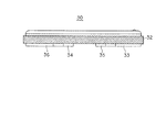
図4は、回転ベゼル30の外観斜視図である。図5は、回転ベゼル30の左側面図であ
る。図6は、回転ベゼル30の右側面図である。
回転ベゼル30は、全体として、リング形状をなしている。また、回転ベゼル30の側
面部には、摩擦力を増して、ユーザの操作性を向上させるための格子溝が切られた把持部
32が形成されている。さらに回転ベゼル30の背面側には、第1押ボタン26を操作禁
止とさせるとともに、回転ベゼル30を滑らかに回動させるべく支持するための係合支持
片33と、第2押ボタン27を操作禁止とさせるための係合片34と、リュウズ25を操
作禁止とさせるための係合片35と、回転ベゼル30を滑らかに回動させるべく支持する
ための支持片36と、を備えている。
FIG. 4 is an external perspective view of the
The rotating
図7は、ケース本体15に回転ベゼル30を組み込んだときの動作説明図である。
回転ベゼル30において、係合支持片33の一方の端部33Aと、支持片36の一方の
端部36Aとで切欠部37が構成されている。
この切欠部37内に規制ピン15Dが配置されており、回転ベゼル30をベゼル収納溝
15C内で図1あるいは図7に示す矢印L方向あるいは矢印R方向回動させた場合に、こ
の規制ピン15Dが端部33Aあるいは端部36Aと当接することにより、回転ベゼル3
0の回動量が規制されることとなる。図7は、回転ベゼル30を矢印L方向に回動させ、
支持片36の端部36Aが規制ピン15Dに当接した状態(操作禁止状態;ロック状態)
を示している。
FIG. 7 is an operation explanatory diagram when the rotating
In the
A
A rotation amount of 0 is restricted. In FIG. 7, the rotating
A state in which the
Is shown.
図8は、リュウズ25の外観斜視図である。図9はリュウズ25の正面図である。
リュウズ25は、滑り止めとして格子溝が切られた、つまみ部50と、操作禁止状態(
ロック状態)において回転ベゼル30の係合片35に係合される、つば部51と、図示し
ない巻き真と結合される一端側が円筒形状とされた杵形状を有する結合部52と、を備え
ている。
この場合において、つまみ部50と、つば部51との間にはギャップ53が形成されて
おり、リュウズ25の操作禁止時には、このギャップ53内に回転ベゼル30の係合片3
5が位置することとなる。
FIG. 8 is an external perspective view of the
The
A
In this case, a
5 will be located.
次にリュウズおよび押ボタンの操作禁止操作について説明する。
図10は、操作禁止状態における要部A−A断端面図である。図11は、操作禁止状態
における要部B−B断端面図である。
ユーザが回転ベゼル30の把持部32を掴んで矢印L方向(図1または図7参照)に回
動させると、支持片36の端部36Aが規制ピン15Dに当接することとなる。
この状態において、図10に示すように、係合片35は、つまみ部50と、つば部51
との間にはギャップ53内に入り込むこととなる。
この結果、ユーザがリュウズ25を引き出して操作しようとしても、つば部51が係合
片35に当接して、引き出すことができず、リュウズ25は操作禁止状態(ロック状態)
となる。
一方、図11に示すように、係合支持片33は、第1押ボタン26の係合支持片33側
の端面26Aに対向する位置となる。
Next, the operation prohibiting operation of the crown and the push button will be described.
FIG. 10 is a cross-sectional view of the main part AA in the operation prohibited state. FIG. 11 is a cross-sectional view of the main part BB in the operation prohibited state.
When the user grasps the
In this state, as shown in FIG. 10, the
In between, it will enter in the
As a result, even if the user pulls out the
It becomes.
On the other hand, as shown in FIG. 11, the
この結果、ユーザが第1押ボタン26を押し込もうとしても、第1押ボタン26の端面
26Aが係合支持片33に当接して押し込むことができず、第1押ボタン26は操作禁止
状態(ロック状態)となる。
第1押ボタン26と同様に、係合片34は、第2押ボタン27の係合片34側の端面に
対向する位置となり、ユーザが第2押ボタン27を押し込もうとしても、第2押ボタン2
7の端面が係合片34に当接して押し込むことができず、第2押ボタン27は操作禁止状
態(ロック状態)となる。
このときには、図1に示すように、状態表示マーカ31は、状態表示部28における「
□LOCK」を指し示し、ユーザは容易に操作禁止状態にあることを容易に認識すること
ができる。
As a result, even if the user tries to push in the
Similar to the
The end face of 7 cannot be pushed in contact with the
At this time, as shown in FIG.
“□ LOCK” is indicated, and the user can easily recognize that the operation is prohibited.
次にリュウズおよび押ボタンの操作許可操作について説明する。
図12は、操作許可状態における要部A−A断端面図である。図13は、操作許可状態
における要部B−B断端面図である。
ユーザが回転ベゼル30の把持部32を掴んで矢印R方向(図1または図7参照)に回
動させると、係合支持片33の端部33Aが規制ピン15Dに当接することとなる。
この状態において、図12に示すように、係合片35は、つまみ部50と、つば部51
との間のギャップ53から抜け出し、操作許可状態(リリース状態)とすることとなる。
この結果、ユーザがリュウズ25を引き出して操作した場合には、係合片35に邪魔さ
れることなく、通常通り、矢印X方向に引き出すことができ、ユーザは、リュウズ25の
つまみ部50をつまんで矢印Z方向に回転させて、仮想線で示す巻き真100を介して操
作を行うことが可能となる。
Next, the operation permission operation of the crown and the push button will be described.
FIG. 12 is a cross-sectional view of the main part AA in the operation permission state. FIG. 13 is a cross-sectional view of the main part BB in the operation permission state.
When the user grasps the
In this state, as shown in FIG. 12, the
And the operation is permitted (release state).
As a result, when the user pulls out the
一方、図13に示すように、係合支持片33も、第1押ボタン26の係合支持片33側
の端面26Aに対向する位置から抜け出すこととなる。
この結果、ユーザが第1押ボタン26を押し込んだ場合には、第1押ボタン26は、コ
イルばね105のばね力に抗して圧縮しつつ、そのまま貫通孔41内を押し込まれ、仮想
線に示す常開スイッチ101を構成する可動接点102を固定接点103に当接させて、
常開スイッチ101を閉状態(オン状態)とする。
第1押ボタン26と同様に、係合片34も、第2押ボタン27の係合片34側の端面に
対向する位置から抜け出すこととなる。
この結果、ユーザが第2押ボタン27を押し込んだ場合には、第2押ボタン27は、図
示しないコイルばねのばね力に抗して圧縮しつつ、そのまま貫通孔42内を押し込まれ、
図示しない対応する常開スイッチを構成する可動接点を固定接点に当接させて、当該常開
スイッチを閉状態(オン状態)とする。
On the other hand, as shown in FIG. 13, the
As a result, when the user pushes the
The normally
Similarly to the
As a result, when the user pushes in the
A movable contact constituting a corresponding normally open switch (not shown) is brought into contact with the fixed contact, and the normally open switch is closed (ON state).
このときには、状態表示マーカ31は、状態表示部28における「□RELEASE」
を指し示し、ユーザは容易に操作許可状態にあることを容易に認識することができる。
以上の説明のように、本実施形態によれば、回転ベゼル30を回動させるだけで、リュ
ウズ25、第1押ボタン26および第2押ボタン27を同時に操作禁止状態(ロック状態
)とすることができ、防水性などの機能性を低下させることなく、製造コストの低減を図
るとともに、操作禁止操作(ロック操作)を容易とすることができる。
以上の説明においては、ベゼル収納溝15Cとしては、金属、合成樹脂等の如何なる材
質のものであっても構わないが、摩擦抵抗が小さく、耐磨耗性の高いものであることが好
ましい。
以上の説明においては、腕時計を例として説明したが、ケース本体の外周部に配置され
る外部操作部材と、ケース本体にスライド可能に支持され、スライドされて外部操作部材
を操作禁止状態とする操作禁止部材と、を備えた携帯型電子機器であれば適用が可能であ
る。
At this time, the
The user can easily recognize that the operation is permitted.
As described above, according to the present embodiment, the
In the above description, the
In the above description, the wristwatch has been described as an example. However, the external operation member disposed on the outer peripheral portion of the case main body and the operation that is slidably supported by the case main body and is slid to place the external operation member in the operation prohibited state. Any portable electronic device including a prohibiting member can be applied.
10…腕時計、11…ケーシング、12…バンド、15…ケース本体、16…表示窓、
17…裏蓋、18…文字板、19…指針、25…リュウズ(外部操作部材)、26…第1
押ボタン(外部操作部材)、27…第2押ボタン(外部操作部材)、30…回転ベゼル(
操作禁止部材)、33…係合支持片(係合片)、34…係合片、35…係合片、36…支
持片。
10 ... Wristwatch, 11 ... Casing, 12 ... Band, 15 ... Case body, 16 ... Display window,
17 ... back cover, 18 ... dial, 19 ... pointer, 25 ... crown (external operation member), 26 ... first
Push button (external operation member), 27 ... second push button (external operation member), 30 ... rotating bezel (
(Operation prohibiting member), 33 ... engagement support piece (engagement piece), 34 ... engagement piece, 35 ... engagement piece, 36 ... support piece.
Claims (6)
前記ケース本体の外周部に配置される外部操作部材と、
前記ケース本体にスライド可能に支持され、スライドされて前記外部操作部材を操作禁
止状態とする操作禁止部材と、
を備えたことを特徴とする携帯型電子機器。 The case body,
An external operation member disposed on the outer periphery of the case body;
An operation prohibiting member that is slidably supported by the case body and is slid to place the external operation member in an operation prohibited state;
A portable electronic device characterized by comprising:
前記操作禁止部材は、係合片を備え、
前記係合片は、前記操作禁止部材が前記スライドされた場合に、前記外部操作部材の所
定の操作方向への移動を阻止する位置に移動されることを特徴とする携帯情報機器。 The portable electronic device according to claim 1, wherein
The operation prohibiting member includes an engagement piece,
The portable information device, wherein the engagement piece is moved to a position that prevents the external operation member from moving in a predetermined operation direction when the operation prohibiting member is slid.
前記操作禁止部材は、係合片を備えた回転ベゼルとして形成され、
前記外部操作部材は、前記回転ベゼルの回転中心に対し、放射方向に操作される部材で
あり、
前記係合片は、前記回転ベゼルが回転方向にスライドされた場合に、前記外部操作部材
の前記放射方向への移動を阻止する位置に移動されることを特徴とする携帯型電子機器。 The portable electronic device according to claim 1, wherein
The operation prohibiting member is formed as a rotating bezel provided with an engagement piece,
The external operation member is a member operated in a radial direction with respect to the rotation center of the rotation bezel,
The portable electronic device according to claim 1, wherein when the rotating bezel is slid in a rotating direction, the engaging piece is moved to a position that prevents the external operation member from moving in the radial direction.
前記携帯型電子機器は、前記外部操作部材としてリュウズあるいは押ボタンの少なくと
もいずれか一方を備えた腕時計であり、
前記回転ベゼルは、回転方向にスライドされた場合に、前記外部操作部材の引出し方向
あるいは押込み方向への移動を阻止する位置に移動されることを特徴とする携帯型電子機
器。 The portable electronic device according to claim 3, wherein
The portable electronic device is a wristwatch provided with at least one of a crown and a push button as the external operation member,
The portable electronic device according to claim 1, wherein when the rotating bezel is slid in a rotating direction, the rotating bezel is moved to a position that prevents the external operation member from moving in a pulling-out direction or a pushing-in direction.
前記外部操作部材は、複数設けられ、
前記操作禁止部材は、前記複数の外部操作部材を略同時に操作禁止状態とすることを特
徴とする携帯型電子機器。 The portable electronic device according to any one of claims 1 to 3,
A plurality of the external operation members are provided,
The portable electronic device, wherein the operation prohibiting member causes the plurality of external operation members to be in an operation prohibited state substantially simultaneously.
前記携帯型電子機器は、前記外部操作部材としてリュウズおよび押ボタンを備えた腕時
計であり、
前記係合片は、前記操作禁止部材が前記スライドされた場合に、前記外部操作部材の引
出し方向あるいは押込み方向への移動を阻止する位置に移動されることを特徴とする携帯
型電子機器。
The portable electronic device according to claim 5, wherein
The portable electronic device is a wristwatch including a crown and a push button as the external operation member,
The portable electronic device according to claim 1, wherein when the operation prohibiting member is slid, the engagement piece is moved to a position that prevents the external operation member from moving in the pulling-out direction or the pushing-in direction.
Priority Applications (1)
| Application Number | Priority Date | Filing Date | Title |
|---|---|---|---|
| JP2004154643A JP2005337792A (en) | 2004-05-25 | 2004-05-25 | Portable electronic device |
Applications Claiming Priority (1)
| Application Number | Priority Date | Filing Date | Title |
|---|---|---|---|
| JP2004154643A JP2005337792A (en) | 2004-05-25 | 2004-05-25 | Portable electronic device |
Publications (1)
| Publication Number | Publication Date |
|---|---|
| JP2005337792A true JP2005337792A (en) | 2005-12-08 |
Family
ID=35491542
Family Applications (1)
| Application Number | Title | Priority Date | Filing Date |
|---|---|---|---|
| JP2004154643A Withdrawn JP2005337792A (en) | 2004-05-25 | 2004-05-25 | Portable electronic device |
Country Status (1)
| Country | Link |
|---|---|
| JP (1) | JP2005337792A (en) |
Cited By (4)
| Publication number | Priority date | Publication date | Assignee | Title |
|---|---|---|---|---|
| JP2018025550A (en) * | 2016-08-12 | 2018-02-15 | オメガ・エス アー | Timepiece with retractable pusher |
| EP3557336A1 (en) | 2018-04-20 | 2019-10-23 | Rolex Sa | System for locking a control element of a timepiece |
| EP3650951A1 (en) | 2018-11-09 | 2020-05-13 | Omega SA | Timepiece comprising a device for locking a valve or a crown |
| EP4047423A1 (en) | 2021-02-17 | 2022-08-24 | Omega SA | Watch provided with a device for locking an external control member |
-
2004
- 2004-05-25 JP JP2004154643A patent/JP2005337792A/en not_active Withdrawn
Cited By (6)
| Publication number | Priority date | Publication date | Assignee | Title |
|---|---|---|---|---|
| JP2018025550A (en) * | 2016-08-12 | 2018-02-15 | オメガ・エス アー | Timepiece with retractable pusher |
| EP3557336A1 (en) | 2018-04-20 | 2019-10-23 | Rolex Sa | System for locking a control element of a timepiece |
| US11809139B2 (en) | 2018-04-20 | 2023-11-07 | Rolex Sa | Locking system for a control element of a timepiece |
| EP3650951A1 (en) | 2018-11-09 | 2020-05-13 | Omega SA | Timepiece comprising a device for locking a valve or a crown |
| EP4047423A1 (en) | 2021-02-17 | 2022-08-24 | Omega SA | Watch provided with a device for locking an external control member |
| US11822291B2 (en) | 2021-02-17 | 2023-11-21 | Omega Sa | Watch equipped with a device for locking an external control unit |
Similar Documents
| Publication | Publication Date | Title |
|---|---|---|
| JP5315024B2 (en) | Portable devices and portable watches | |
| JP6578975B2 (en) | Clock with rotating bezel | |
| US20090046542A1 (en) | Crown protection device for wristwatch | |
| US8721171B2 (en) | Switch device and wristwatch | |
| JP2005292139A (en) | Push-button clock | |
| JP2010190856A (en) | Portable watch | |
| JP2005108630A (en) | Operating part structure and watch | |
| JP2008076067A (en) | Watch | |
| JP5285546B2 (en) | Hand-wound portable watch and operating method of crown provided in this watch | |
| JP2007303843A (en) | Reversible display apparatus | |
| JP5389424B2 (en) | Portable devices and portable watches | |
| JP2008010599A (en) | Locking device | |
| JP2005337792A (en) | Portable electronic device | |
| JP2005127816A (en) | Watch | |
| JP5975304B2 (en) | Switch device and clock | |
| JP4533650B2 (en) | Cell phone clock | |
| JP6579878B2 (en) | Locking mechanism for operation member | |
| JP6613739B2 (en) | Switch device and clock | |
| JP2014026723A (en) | Apparatus with operation input member | |
| JP3810691B2 (en) | Cell phone clock | |
| JP2003007164A (en) | Button structure and portable equipment provided with it | |
| JP2008170494A (en) | Lock structure for mode dial | |
| JP2015068778A (en) | Moving structure of operating member, and wrist watch | |
| JP2005326280A (en) | Case for timepiece and timepiece | |
| JP7199137B2 (en) | Portable locking/unlocking display device |
Legal Events
| Date | Code | Title | Description |
|---|---|---|---|
| RD04 | Notification of resignation of power of attorney |
Free format text: JAPANESE INTERMEDIATE CODE: A7424 Effective date: 20070403 |
|
| A300 | Withdrawal of application because of no request for examination |
Free format text: JAPANESE INTERMEDIATE CODE: A300 Effective date: 20070807 |