JP2005325115A - Contrast agent for modality combination type imaging and modality combination type imaging method and imaging system - Google Patents
Contrast agent for modality combination type imaging and modality combination type imaging method and imaging system Download PDFInfo
- Publication number
- JP2005325115A JP2005325115A JP2005139265A JP2005139265A JP2005325115A JP 2005325115 A JP2005325115 A JP 2005325115A JP 2005139265 A JP2005139265 A JP 2005139265A JP 2005139265 A JP2005139265 A JP 2005139265A JP 2005325115 A JP2005325115 A JP 2005325115A
- Authority
- JP
- Japan
- Prior art keywords
- contrast agent
- component
- modality
- imaging system
- fluorescent component
- Prior art date
- Legal status (The legal status is an assumption and is not a legal conclusion. Google has not performed a legal analysis and makes no representation as to the accuracy of the status listed.)
- Withdrawn
Links
- IFTRQJLVEBNKJK-UHFFFAOYSA-N CCC1CCCC1 Chemical compound CCC1CCCC1 IFTRQJLVEBNKJK-UHFFFAOYSA-N 0.000 description 1
Images
Classifications
-
- A—HUMAN NECESSITIES
- A61—MEDICAL OR VETERINARY SCIENCE; HYGIENE
- A61B—DIAGNOSIS; SURGERY; IDENTIFICATION
- A61B5/00—Measuring for diagnostic purposes; Identification of persons
- A61B5/0059—Measuring for diagnostic purposes; Identification of persons using light, e.g. diagnosis by transillumination, diascopy, fluorescence
-
- A—HUMAN NECESSITIES
- A61—MEDICAL OR VETERINARY SCIENCE; HYGIENE
- A61K—PREPARATIONS FOR MEDICAL, DENTAL OR TOILETRY PURPOSES
- A61K41/00—Medicinal preparations obtained by treating materials with wave energy or particle radiation ; Therapies using these preparations
- A61K41/0028—Disruption, e.g. by heat or ultrasounds, sonophysical or sonochemical activation, e.g. thermosensitive or heat-sensitive liposomes, disruption of calculi with a medicinal preparation and ultrasounds
-
- A—HUMAN NECESSITIES
- A61—MEDICAL OR VETERINARY SCIENCE; HYGIENE
- A61K—PREPARATIONS FOR MEDICAL, DENTAL OR TOILETRY PURPOSES
- A61K49/00—Preparations for testing in vivo
- A61K49/001—Preparation for luminescence or biological staining
- A61K49/0063—Preparation for luminescence or biological staining characterised by a special physical or galenical form, e.g. emulsions, microspheres
- A61K49/0069—Preparation for luminescence or biological staining characterised by a special physical or galenical form, e.g. emulsions, microspheres the agent being in a particular physical galenical form
- A61K49/0089—Particulate, powder, adsorbate, bead, sphere
Landscapes
- Health & Medical Sciences (AREA)
- Life Sciences & Earth Sciences (AREA)
- Animal Behavior & Ethology (AREA)
- Veterinary Medicine (AREA)
- Public Health (AREA)
- General Health & Medical Sciences (AREA)
- Biomedical Technology (AREA)
- Engineering & Computer Science (AREA)
- Epidemiology (AREA)
- Physics & Mathematics (AREA)
- Chemical & Material Sciences (AREA)
- Heart & Thoracic Surgery (AREA)
- Molecular Biology (AREA)
- Pathology (AREA)
- Biophysics (AREA)
- Medical Informatics (AREA)
- Surgery (AREA)
- Medicinal Chemistry (AREA)
- Pharmacology & Pharmacy (AREA)
- Ultra Sonic Daignosis Equipment (AREA)
- Medicines Containing Antibodies Or Antigens For Use As Internal Diagnostic Agents (AREA)
- Measuring And Recording Apparatus For Diagnosis (AREA)
- Apparatus For Radiation Diagnosis (AREA)
- Investigating, Analyzing Materials By Fluorescence Or Luminescence (AREA)
Abstract
Description
本発明は一般的には、診断撮像の分野に関し、さらに具体的には、例えば光学的撮像と超音波撮像との結合のようなモダリティ結合型撮像のために染料及び消光剤と共役した造影剤を用いる撮像方法及びイメージング・システムに関する。 The present invention relates generally to the field of diagnostic imaging, and more specifically, contrast agents conjugated with dyes and quenchers for modality-coupled imaging, such as combining optical and ultrasound imaging. The present invention relates to an imaging method and an imaging system using the same.
現在の医療施設では、健康状態を識別し、診断して治療するために医療診断及びイメージング・システムをしばしば用いる。診断撮像とは、器官又は組織の構造的パターン又は機能的パターンの診断評価のための任意の視覚的表示を指す。診断撮像は、物理的刺激若しくは化学的刺激のいずれか、又はこれら両方の刺激に対する生理学的応答及び代謝応答を測定することを含んでいる。現在、医療診断及びイメージング・システムとして多くのモダリティが存在している。これらのモダリティには、超音波システム、光学的イメージング・システム、計算機式断層写真法(CT)システム、X線システム(従来のシステム及びディジタル型イメージング・システムの両方を含む)、陽電子放出断層写真法(PET)システム、シングル・フォトン・エミッション計算機式断層写真法(SPECT)システム及び磁気共鳴イメージング(MRI)システム等がある。多くの例で、担当医又は放射線技師が、1種又は複数の撮像モダリティによる関連部位及び組織の詳細な画像で従来の検査を補完して初めて、最終的な診断及び治療が進行する。 Current medical facilities often use medical diagnostic and imaging systems to identify, diagnose and treat health conditions. Diagnostic imaging refers to any visual display for diagnostic evaluation of structural or functional patterns of organs or tissues. Diagnostic imaging involves measuring physiological and metabolic responses to either physical or chemical stimuli, or both. Currently, many modalities exist as medical diagnostic and imaging systems. These modalities include ultrasound systems, optical imaging systems, computed tomography (CT) systems, X-ray systems (including both conventional and digital imaging systems), positron emission tomography (PET) systems, single photon emission computed tomography (SPECT) systems, magnetic resonance imaging (MRI) systems, and the like. In many instances, the final diagnosis and treatment will only progress after the attending physician or radiologist supplements the conventional examination with detailed images of relevant sites and tissues from one or more imaging modalities.
これらのイメージング・システムの幾つかは、被検体の解剖学的構造ではなく疾患状態に伴う分子過程を撮像することに焦点を当てる。この形式の撮像を一般に分子撮像(molecular imaging)と呼ぶ。特定の物質の分子濃度のピコモル水準での変化を生ずるような生理学的活動の微小変化は、疾患の早期の前兆的兆候を与えることができる。かかる変化の検出には高感度の撮像手法が必要とされる。 Some of these imaging systems focus on imaging molecular processes associated with disease states rather than subject anatomy. This type of imaging is generally referred to as molecular imaging. Minor changes in physiological activity that result in changes in the molecular concentration of a particular substance at the picomolar level can give early signs of disease. Detection of such a change requires a highly sensitive imaging method.
現状で、十分に確立した分子撮像の方法では核医学を用いており、放射性医薬品(特定の目標部位に標的を定めるもの)を患者の体内に注入する。放射性医薬品の減衰を用いて薬剤の生体分布の画像を構築する。この方法は極めて高感度であるが、空間分解能及び解剖学的位置揃え(registration)が限定されており、さらに患者及び医師が放射線を被曝する欠点がある。 At present, well-established molecular imaging methods use nuclear medicine and inject a radiopharmaceutical (targeted at a specific target site) into the patient's body. An image of the biodistribution of the drug is constructed using the attenuation of the radiopharmaceutical. While this method is extremely sensitive, it has limited spatial resolution and anatomical registration and has the disadvantages of exposing patients and physicians to radiation.
光学的撮像は分子撮像の代替的形態であって、患者に何らかの波長の光を透過させることにより作用する。例えば、光学的撮像は一般的には、近赤外線部分の波長スペクトルで作用する。表面下光学的撮像の利点としては、視覚的画像が高分解能であること及び画像が読影し易いことが挙げられる。しかしながら、この手法の視野範囲は大部分で体表面の撮像に限定されている。このモダリティの表面下撮像についての制限は光吸収及び光散乱によるものである。表面下撮像の場合には、光学的撮像は空間分解能及び解剖学的位置揃えが比較的劣る。 Optical imaging is an alternative form of molecular imaging that works by allowing the patient to transmit some wavelength of light. For example, optical imaging typically operates in the near infrared portion of the wavelength spectrum. Advantages of subsurface optical imaging include high resolution of the visual image and ease of image interpretation. However, the visual field range of this method is mostly limited to imaging of the body surface. The limitation of submodality imaging of this modality is due to light absorption and light scattering. In the case of subsurface imaging, optical imaging has relatively poor spatial resolution and anatomical alignment.
機能撮像とは対照的に、超音波撮像は患者の解剖学的構造の画像を迅速に得るための十分に確立されたモダリティである。動作時には、超音波イメージング・システムは被検体の体内に超音波を送波し、続いて音響インピーダンスの異なる組織同士の間の界面で発生された反射波を受波する。組織の位置は、反射波の到達時刻及び近似的な速度に基づいて算出することができる。このようにして、超音波イメージング・システムは何らかの解剖学的構造の形状及び位置を識別することができる。この手法には患者の待ち時間が短縮される、検査手順が高速化する等の固有の利点があるが、この手法の主な欠点は画像雑音が多いことである。この理由で、画像の読影を行なって適正な診断を下すためにはかなりの技量が要求される。 In contrast to functional imaging, ultrasound imaging is a well-established modality for quickly obtaining images of patient anatomy. In operation, the ultrasound imaging system transmits ultrasound waves into the body of the subject, and subsequently receives reflected waves generated at the interface between tissues having different acoustic impedances. The position of the tissue can be calculated based on the arrival time of the reflected wave and the approximate speed. In this way, the ultrasound imaging system can identify the shape and position of some anatomical structure. While this approach has inherent advantages such as reduced patient waiting time and faster examination procedures, the main drawback of this approach is that there is a lot of image noise. For this reason, considerable skill is required to interpret an image and make an appropriate diagnosis.
これらの異なる撮像モダリティの利点及び欠点を鑑みるに、機能撮像モダリティ(例えば光学的撮像)の高い分子感度と解剖学的撮像モダリティの空間分解能(例えば超音波)とを結合する手法が必要とされている。 In view of the advantages and disadvantages of these different imaging modalities, there is a need for a technique that combines the high molecular sensitivity of functional imaging modalities (eg optical imaging) with the spatial resolution (eg ultrasound) of anatomical imaging modalities. Yes.
簡単に述べると、本発明の一観点によれば、モダリティ結合型イメージング・システム用の造影剤が、モダリティ結合型イメージング・システムからの放出に応答して変化する幾何学的構成を有する変形可能な粒子を含んでいる。また、変形可能な粒子は、電磁線を放出するように構成されている蛍光成分と、蛍光成分から離隔しており、蛍光成分からの電磁線の一部を吸収するように構成されている消光成分とを含んでいる。 Briefly, according to one aspect of the present invention, a contrast agent for a modality-coupled imaging system has a deformable geometry that changes in response to release from the modality-coupled imaging system. Contains particles. Also, the deformable particles are separated from the fluorescent component configured to emit electromagnetic radiation and the quenching configured to absorb a portion of the electromagnetic radiation from the fluorescent component. Contains ingredients.
本発明の他の観点によれば、モダリティ結合型イメージング・システムが、第一のモダリティの第一の撮像装置と、第一のモダリティとは異なる第二のモダリティの第二の撮像装置とを含んでいる。第一及び第二の撮像装置は共に、被検体に受容されるように構成されている造影剤と相互作用するように構成されている。造影剤は、第一の撮像装置からの放出に応答して変化する幾何学的構成を有する変形可能な粒子を含んでいる。変形可能な粒子はまた、第二の撮像装置によって検出可能な電磁線を放出するように構成されている蛍光成分と、上述の幾何学的構成に基づく距離を隔てて蛍光成分から離隔しており、蛍光成分からの電磁線の一部を吸収するように構成されている消光成分とを含んでいる。 According to another aspect of the invention, a modality-coupled imaging system includes a first imaging device of a first modality and a second imaging device of a second modality different from the first modality. It is out. Both the first and second imaging devices are configured to interact with a contrast agent that is configured to be received by the subject. The contrast agent includes deformable particles having a geometric configuration that changes in response to release from the first imaging device. The deformable particles are also separated from the fluorescent component at a distance based on the geometric configuration described above, and the fluorescent component configured to emit electromagnetic radiation detectable by the second imaging device. And a quenching component configured to absorb a portion of the electromagnetic radiation from the fluorescent component.
本発明の他の観点によれば、モダリティ結合型イメージング・システムの利用方法が、変形可能な粒子を含んだ造影剤の溶液による診断に被検体を配置するステップを含んでいる。変形可能な粒子は、電磁線式撮像装置によって検出可能な電磁線を放出するように構成されている蛍光成分と、変形可能な粒子の幾何学的構成に基づく距離を隔てて蛍光成分から離隔されており、蛍光成分によって放出される電磁線の一部を吸収するように構成されている消光成分とを含んでいる。消光成分はまた、蛍光共鳴エネルギ転移機構によって蛍光成分からの電磁線の放出を伴わないエネルギ転移を生ずることもできる。モダリティ結合型イメージング・システムのこの利用方法はまた、超音波イメージング・システムからの超音波を被検体の関心領域に位置する超音波プローブの関心領域に印加するステップと、電磁励起源を用いて関心領域に電磁線を照射するステップと、超音波プローブを用いて反射した超音波信号を検出するステップと、電磁線検出器を用いて造影剤からの電磁線を検出するステップと、別個であるが位置揃えされた2枚の画像を得るように、検出された超音波信号及び電磁線を処理するステップと、最後に、モダリティ結合型イメージング・システムからの画像を表示するステップと、を含んでいる。 According to another aspect of the present invention, a method of using a modality coupled imaging system includes the step of placing a subject for diagnosis with a solution of a contrast agent containing deformable particles. The deformable particle is separated from the fluorescent component at a distance based on the geometric configuration of the deformable particle and the fluorescent component configured to emit electromagnetic radiation detectable by the electromagnetic imaging device. And a quenching component configured to absorb part of the electromagnetic radiation emitted by the fluorescent component. The quenching component can also cause energy transfer without emission of electromagnetic radiation from the fluorescent component by a fluorescence resonance energy transfer mechanism. This method of using the modality coupled imaging system also includes applying ultrasound from the ultrasound imaging system to a region of interest of an ultrasound probe located in the region of interest of the subject and using an electromagnetic excitation source to generate the interest. The steps of irradiating the region with electromagnetic radiation, detecting the reflected ultrasonic signal using an ultrasonic probe, and detecting electromagnetic radiation from the contrast agent using an electromagnetic detector are separate. Processing the detected ultrasound signal and electromagnetic radiation to obtain two aligned images, and finally displaying the image from the modality coupled imaging system. .
本発明の上述の特徴、観点及び利点、並びに他の特徴、観点及び利点は、添付図面を参照して以下の詳細な説明を読解するとさらに十分に理解されよう。各図面全体を通じて類似の参照符号は類似の部材を表わす。 The foregoing features, aspects, and advantages of the present invention, as well as other features, aspects, and advantages will be more fully understood when the following detailed description is read with reference to the accompanying drawings. Like reference numerals represent like parts throughout the drawings.
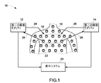
図面について説明する。先ず、図1には、モダリティ結合型イメージング・システム10が、第一の撮像モダリティ12、第二の撮像モダリティ14、造影剤18の溶液を注入された被検体16、並びに第一及び第二の撮像モダリティからの画像を表示することが可能な表示システム20を含んでいるものとして模式的に図示されている。造影剤18は一般的には、腫瘍のような関心領域に蓄積して、これら関心領域の撮像を強調する。後に詳述するように、造影剤18の幾つかの実施形態は、蛍光成分と、蛍光成分から離隔した消光成分とを有する変形可能な粒子を含んでおり、変形可能な粒子の幾何学的構成の変化が蛍光成分と消光成分との間の距離を変化させるようにしている。結果として、造影剤18から放出される電磁線が、蛍光成分と消光成分との間の距離と共に変化する。距離が大きいほど放出される電磁線が多くなり、距離が小さいほど放射線が少なくなる。動作時には、フェルスター(Forster)共鳴エネルギ転移としても知られる放射線放出と距離との間のこの相関は、造影剤18から放出される放射線の位置決定を容易にする。
The drawings will be described. First, referring to FIG. 1, a combined
本手法の幾つかの観点では、第一の撮像モダリティ12は、所望の周波数の圧力波24を被検体16の関心領域22に集中させ、関心領域22から反射した圧力波26を回収して画像を得る。例えば、第一の撮像モダリティ12の一実施形態は、関心領域22において超音波を送受する超音波プローブ32を含んでいる。関心領域22では、圧力波24は造影剤18の幾何学的構成を変化させるように作用し、これにより、造影剤18によって放出される蛍光を圧力波24の周波数で変調させる。第二の撮像モダリティ14の幾つかの実施形態はこの蛍光変調を検出して、集中域22に基づいて実質的に位置決定された光学的分子画像を形成する。動作時には、第二の撮像モダリティ14は電磁線28を関心領域22に送波した後に、第一の撮像モダリティ12と造影剤18と電磁線28との間の相互作用を利用して画像を形成する。表示システム20は、2種の異なるモダリティからの画像を別個に、又は各画像を互いの上に重ね合わせた複合画像としてのいずれかで表示することができる。本手法は、機能撮像モダリティ(例えば光学的撮像)の高い分子感度という利点と、解剖学的撮像モダリティ(例えば超音波撮像)の高い空間分解能という利点とを結合して、画質及び診断を改善する。
In some aspects of the present technique, the
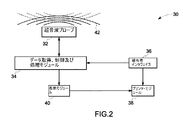
図2は、例示的な第一の撮像モダリティ12を、超音波プローブ32、データ取得及び処理モジュール34、操作者インタフェイス36、プリンタ・モジュール38、並びに表示モジュール40を含む超音波システム30として示す。
FIG. 2 illustrates an exemplary
動作時には、超音波プローブ32は、被検体16の関心領域に対して超音波42を送受する。超音波プローブ32は、本手法の幾つかの観点によれば、超音波トランスデューサ、圧電結晶、光音響トランスデューサ、及び微小電気機械システム装置例えば容量型微細加工超音波トランスデューサ(cMUT)の少なくとも一つを含んでいる。超音波関連業者には認められるように、超音波42は送波、反射及び屈折に関して幾何光学の諸法則に従う。また、超音波の周波数が高いほど、超音波42のより集中した標的設定が容易になる。超音波システム30の動作時には、被検体から反射した超音波42は、様々な組織、器官、腫瘍及び解剖学的構造の厚み、大きさ及び位置に関する情報を、送波された超音波と関連付けて担持している。幾つかの実施形態では、超音波プローブ32は手掌型であってもよいし、又はロボット・アセンブリを用いて機械的に配置されるものであってもよい。
During operation, the
データ取得、制御及び処理モジュール34は超音波プローブ32からの情報を送受する。モジュール34は、超音波プローブ32によって送波された超音波42の強度、幅、持続時間及び周波数を制御して、集中域22から反射した超音波42に含まれる情報を復号して認識可能な電気信号及び電子信号を発生する。一旦、情報が取得されたら、超音波プローブ32の関心領域22内に配置された対象の画像が再構成される。
The data acquisition, control and
操作者インタフェイス36は、キーボード、マウス、及び他の利用者対話装置を含んでいてよい。操作者インタフェイス36を用いて、超音波検査を設定したりシステム・レベルの構成変更を行なったりする設定をカスタマイズすることができる。操作者インタフェイス36は、データ取得、制御及び処理モジュール34、並びにプリンタ・モジュール38に接続されている。プリンタ・モジュール38は、得られた超音波画像のハード・コピーをグレイ・スケール又はカラーのいずれかで形成するのに用いられる。表示モジュール40は、データ取得及び処理モジュール34からのデータに基づいて被検体16の関心領域22の内部の対象の再構成画像を表示する。
The
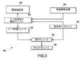
図3は、本手法の幾つかの実施形態による例示的な光学的イメージング・システム44を示す。幾つかの実施形態では、光学的イメージング・システム44は図2の超音波イメージング・システム30と連動する。図示の光学的イメージング・システム44は、電磁励起源46、電磁線検出器48、データ取得及び制御モジュール50、データ処理モジュール52、操作者インタフェイス54、表示モジュール56及びプリンタ・モジュール58を含んでいる。後にさらに詳細に議論するように、光学的イメージング・システム44は、超音波システム30と、被検体16の体内に注入されて被検体16の関心領域22に位置する造影剤18の溶液と、電磁励起源46からの電磁線との間の相互作用を記録する。
FIG. 3 illustrates an exemplary
図示の電磁励起源46は、固体発光ダイオード(LED)、有機発光ダイオード(OLED)、レーザ、白熱灯、ハロゲン灯、アーク灯及びその他任意の適当な光源の少なくとも一つを有する。例えば、電磁励起源46は、蛍光成分の吸収波長に合わせて約300ナノメートル〜約2マイクロメートルの放射線を放出することができる。電磁励起源46の幾つかの実施形態は、時間不変型、シヌソイド変化型、パルス変化型又は時間変化型のいずれかの強度を有する電磁線を放出する。電磁線はまた、単一波長又は約300ナノメートル〜約2マイクロメートルのスペクトルを網羅する多種波長を含んでいてよい。電磁励起源46から集中域22への照射を行なうのに光ファイバ及び光ファイバ・バンドルのような光ファイバ・チャネルを用いてもよい。
The illustrated
図示の電磁線検出器48は、光電子増倍管、電荷結合素子、映像増倍管(イメージ・インテンシファイア)、フォトダイオード、アバランシュ・フォトダイオード、及び時間変化型電磁線束を時間変化型電気信号へ変換し得る任意の適当な装置の少なくとも一つを有する。光ファイバのアレイもまた、電磁線検出器46から集中域22の近くまで延在して電磁線を収集することができる。例えば、被検体16上に直接又は被検体16の表面の近くのいずれかに光ファイバを装着してよい。
The illustrated
図示のデータ取得及び制御モジュール50は、電磁励起源46へ制御信号を送信して、電磁線検出器48から光信号を受信する。データ取得及び制御モジュール50はまた、データ処理モジュール52及びユーザ・インタフェイス・モジュール54とも連絡している。データ処理モジュール52は、電磁線検出器48から得られた情報を用いて画像を再構成する。ユーザ・インタフェイス・モジュール54を用いて、光学的イメージング・システム44の構成に変更を加え、また表示モジュール56及びプリンタ・モジュール58に制御命令を供給する。
The illustrated data acquisition and
幾つかの実施形態では、モダリティ結合型イメージング・システム10は、上で詳述した超音波イメージング・システム及び光学的イメージング・システムの両方の機能を含んでいる。図4及び図5は、かかるモダリティ結合型イメージング・システムの例示的な実施形態である。図4の実施形態は単一ユニットを含んでおり、単一ユニットの中央に配置された超音波イメージング・システム30の超音波プローブ32と、単一ユニットの両側に配置された光学的イメージング・システム44の電磁励起源46及び電磁検出器48とを有する。図5の実施形態は単一ユニットを含んでおり、単一ユニットの中央に配置された超音波イメージング・システム30の超音波プローブ32と、超音波プローブ32の両側に位置する光学的イメージング・システム44の一対の電磁線検出器48とを有する。
In some embodiments, the modality combined
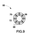
図6〜図9を参照して後述するように、上述のイメージング・システム10、30及び44は多様な異なる実施形態の造影剤と相互作用する。図6は、変形可能な粒子を含んだ造影剤18の実施形態64の線図であり、変形可能な粒子は殻66と殻66の内部に配置された内部物質68とを含んでいる。変形可能な粒子はまた、1対又は多数の蛍光成分70−消光成分72の対を含んでおり、各々の成分が、変形可能な粒子の外面に結合している。図7は、変形可能な粒子を含んだ造影剤18の代替的な実施形態76の線図であり、変形可能な粒子は殻66と殻66の内部に配置された内部物質68とを含んでいる。変形可能な粒子はまた、変形可能な粒子の殻66の内部に配置された蛍光成分70−消光成分72の対の少なくとも1対を含んでおり、各々の成分が、リンカー成分74によって変形可能な粒子の内面に結合している。図8は、変形可能な粒子を含んだ造影剤18のもう一つの代替的な実施形態78の線図であり、多数の蛍光成分70−消光成分72の対が変形可能な粒子の殻66を形成している。図9は、造影剤18のさらにもう一つの実施形態80の線図であり、蛍光成分70及び消光成分72の少なくとも一方が変形可能な粒子の多数の層に別個に配置されており、内殻が圧縮性核を含んでいる。以上の実施形態の各々では、音波42(例えば超音波)が変形可能な粒子の幾何学的構成を変化させ、これにより蛍光成分−消光成分の対の間の距離を変化させる。以下で説明する各図で、造影剤18の組成、並びに造影剤18と図2に示す超音波イメージング・システム30及び図3に示す光学的イメージング・システム44との相互作用をさらに詳細に説明する。
As described below with reference to FIGS. 6-9, the
変形可能な粒子の殻66は、ポリマー、タンパク質及び両親媒性分子の少なくとも一つを含んでいる。両親媒性物質とは疎水性領域及び親水性領域の両方を有する界面活性剤のような物質である。この用語は、ホスホリピドのような小分子に当てはまる。両親媒性分子は、イオン性又は非イオン性の少なくとも1種の界面活性剤を含み、この界面活性剤は、続く化学的修飾のための反応性の結合手(handle)を与える少なくとも1個の官能基を含む。殻66の成分は、さらなる化学的修飾のための反応性の結合手を含む少なくとも1個の官能基を含む。殻66の内部に配置されている内部物質68は圧縮可能であって、幾つかの実施形態では、空気、六フッ化イオウ、パーフロロカーボン、気泡、気体前駆体及びポリマーの少なくとも一つを含んでいてよい。蛍光成分70は蛍光染料を含む。例えば、蛍光染料としては、インドシアニングリーン(ICG)、シアニン5.5(CY5.5)、シアニン7.5(CY7.5)、フルオレセイン、ローダミン、黄色蛍光タンパク質(YFP)、緑色蛍光タンパク質(GFP)、イソチオシアン酸フルオレセイン(FITC)及びこれらの誘導体等がある。消光成分72は、公知の消光性物質及びこの誘導体の少なくとも一つを含む。上述の蛍光成分は、適当な分子濃度及び当該蛍光成分に特徴的な分離レベルでは自己消光性であり得る。造影剤18はまた、変形可能な粒子に共役しており特定の生化学的標識に選択的に結合する化学物質を含んでいてよい。このことは、造影剤が、異常組織と正常組織との間の差に基づく選択的な蓄積によって異常組織を能動的に目標設定し得ることを意味する。例えば、生化学的標識としては、モノクローナル抗体、抗体例えばトリアデノウイルス(FAV)の断片、抗体の構造体、ポリペプチド、他の小有機分子及びこれらの組み合わせ等がある。
The
蛍光成分70は、入射波長の電磁線を吸収してこれよりも長い波長の電磁線を放出する性質を有する。消光成分72は、蛍光成分70によって放出される波長の電磁線を吸収する性質を有する。蛍光成分70の一作用は、超音波プローブ32の集中域22から出力される光を最大化することにある。消光成分72の一作用は、被検体16の関心領域の近くでない粒子によって発生される蛍光の強度を最小化することにより信号対雑音比を最大化することにある。
The
蛍光成分70と消光成分72との間の距離が特性距離よりも小さく、電磁励起源46からの電磁線が被検体16の関心領域に入射する場合には、蛍光成分70によって(図3に示す電磁励起源46からの入射電磁線を吸収した後に)放出される電磁線は消光成分72によって消光される。消光は、消光成分72が蛍光成分70によって放出される電磁線の殆どを吸収したときに生ずる。消光はまた、蛍光成分70から電磁線が一切放出されない状態で消光成分72が蛍光成分70からのエネルギを吸収する蛍光共鳴エネルギ転移機構によっても生ずることができる。結果として、電磁線検出器48によって検出されるには不十分な造影剤18からの弱い光出力が存在する。この点で、造影剤18はオフ状態にあると言える。オフ状態の造影剤の典型的な大きさは15マイクロメートル径未満である。蛍光成分70と消光成分72との間の離隔距離が、フェルスター距離と呼ばれる特性距離を少なくとも上回っており、電磁励起源46からの電磁線が被検体16の集中域22に入射した場合には、蛍光成分70によって放出される電磁線は消光成分72によって吸収されることはなく、造影剤18からの光出力が存在する。この状態では、造影剤18はオン状態にあると言える。
When the distance between the
蛍光成分70と消光成分72との間の離隔距離の増大は、造影剤18が、図2に示す提案の超音波イメージング・システム30からの超音波42で照射されると生ずる。超音波イメージング・システム30からの超音波42のような音響的な圧力の影響の下で、造影剤18は幾何学的構成の変化を生ずる。幾つかの実施形態では、超音波42は造影剤18の容積を増大させる。超音波42のパルス的な性質のため、造影剤18は圧縮及び膨張を繰り返して容積変化を生じ、この容積変化は幾つかの実施形態では300%程度であり得る。容積変化から、蛍光成分70と消光成分72との間の離隔距離の変化が生ずる。従って、超音波42が造影剤18と相互作用する度毎に光出力の変調が生ずる。従って、この光出力は、提案の光学的イメージング・システム44のデータ取得及び制御モジュール50が電磁線検出器48を介して光学的データを収集し、データ処理モジュール52によって光学的データを処理することを可能にする。光学的イメージング・システム44のデータ処理モジュール52はこの光学的データを計算して、図2に示す超音波システム30からの超音波画像と互いに位置揃えされた光学的画像を得る。
An increase in the separation distance between the
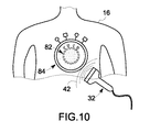
図10は、本手法の実施形態による超音波イメージング・システム30からの超音波42と、単一の造影剤18との間の相互作用の例示的な図である。超音波42が造影剤18に衝突する前には、造影剤18は基底状態又は非励起状態82にあり、蛍光成分70と消光成分72との間の離隔距離は特性距離よりも小さい。超音波42が造影剤18に衝突すると、上述の造影剤18の特性によって、造影剤18は蛍光成分70と消光成分72との間の離隔距離を増大させるような幾何学的構成の変化を生ずる。この段階で、造影剤18は励起状態84にあり、蛍光成分70と消光成分72との間の離隔距離は少なくとも特性距離を上回る。
FIG. 10 is an exemplary diagram of the interaction between the
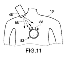
図11は、本手法の実施形態による単一の造影剤18と光学的イメージング・システム44からの電磁励起源46との間の相互作用の例示的な図である。電磁励起源46は、造影剤18の吸収波長に合致した約300ナノメートル〜約2マイクロメートルの電磁線86を放出する。蛍光成分70は入射した電磁線86を吸収して、これよりも長い波長の電磁線88を放出する。しかしながら、造影剤18は非励起状態82にあるので、蛍光成分70と消光成分72との間の距離は特性距離よりも小さく、これら二成分の間には最大エネルギ転移が存在する。最大エネルギ転移が存在するので、消光成分72は蛍光成分70によって放出される電磁線88を吸収し、造影剤18から電磁線の形態の弱い出力が存在する。
FIG. 11 is an exemplary diagram of the interaction between a
図12は、本手法の実施形態による造影剤18について上で述べた超音波及び光学的撮像モダリティの結合型相互作用を示す。動作時には、電磁励起源46からの電磁線86が超音波プローブ32の集中域22において造影剤18に入射する。先ず、超音波プローブ32からの超音波42が造影剤18に衝突し、これにより造影剤18のオフ状態82からオン状態84への状態変化を生じ、造影剤18の変形可能な粒子の膨張が結果的に生ずる。前述のように、膨張は蛍光成分70と消光成分72との間の離隔距離の増大を生ずる。電磁線86が、励起した造影剤84の蛍光成分70に入射するので、光学的イメージング・システム44の電磁線検出器48は造影剤18によって放出される電磁線88の形態の出力を検出する。本手法の代替的な実施形態では、以下に述べるように、超音波パルスを受けたときに造影剤18が異なる振る舞いをしてもよい。造影剤が超音波パルスを受けるときのことを考える。すなわち、この代替的な実施形態では、造影剤18は、各々の超音波が造影剤18を通る毎に造影剤の容積が増大するような態様で幾何学的構成を変化させることができる。超音波42がオフになっても、造影剤18の容積が急激に収縮して元の状態に戻ることはない。代わりに、造影剤18の容積は、基底状態に達するまで幾何学的構成の緩やかな収縮を経る。
FIG. 12 illustrates the combined interaction of the ultrasound and optical imaging modalities described above for
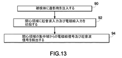
図13は、本手法の実施形態による図1に示すモダリティ結合型イメージング・システム10の例示的な利用方法を示す。この方法は、ステップ90で、被検体16に造影剤18を注入することを含んでいる。十分な時間量の後には、造影剤18は被検体16の体内を流れて関心領域22に到達しており、ここで撮像を行なって診断を支援することになる。ステップ92では、モダリティ結合型イメージング・システム10からの入力(超音波及び電磁線)を本書で上述したように被検体16の集中域22に印加する。造影剤18は超音波イメージング・システム30及び光学的イメージング・システム44の両方と、本書で上述したような態様で相互作用する。ステップ94では、モダリティ結合型イメージング・システム10は、造影剤18の多数の蛍光成分70によって放出された電磁線、及び被検体の集中域から反射した超音波42を検出する。一実施形態では、これにより、超音波イメージング・システム12から得られる放射線/超音波画像と、造影剤18によって放出され光学的イメージング・システム14の電磁線検出器48によって検出される電磁線の強度によって測定される造影剤の濃度との同時マッピングが可能になる。この電磁線の強度は、受け取ったままの変調された強度であってもよいし、或いはあらゆる介在組織又は器官によって生ずる減衰の推定値に基づいて修正された強度であってもよい。最後に、ステップ96で、第一の撮像モダリティ12及び第二の撮像モダリティ14からの互いに位置揃えされた画像を表示する。表示は、別個の表示であってもよいし、或いは二つの異なるモダリティからの画像を互いに重ね合わせ表示した複合型表示であってもよい。
FIG. 13 illustrates an exemplary method of using the modality combined
図14は、本手法の幾つかの実施形態による造影剤(例えば図6〜図9に示すようなもの)及びモダリティ結合型イメージング・システムの作用方法を示す図である。造影剤は、モダリティ結合型イメージング・システム(例えば図1に示すようなもの)からの放出に応答して変化する幾何学的構成を有する変形可能な粒子を含んでいる。変形可能な粒子は蛍光成分及び消光成分の少なくとも一方を含む。 FIG. 14 illustrates how a contrast agent (eg, as shown in FIGS. 6-9) and a modality-coupled imaging system work in accordance with some embodiments of the present technique. The contrast agent includes deformable particles having a geometric configuration that changes in response to release from a modality coupled imaging system (eg, as shown in FIG. 1). The deformable particle includes at least one of a fluorescent component and a quenching component.
ステップ98では、造影剤18が先ず、被検体16の関心領域22に蓄積する。ステップ100では、造影剤18が超音波及び電磁線に応答して励起し又は刺激される。例えば、蛍光成分70からの電磁線の放出を生じさせるように、モダリティ結合型イメージング・システム10から電磁線28の形態の入力を造影剤18を含む関心領域22に印加することができる。消光成分は、蛍光成分70によって放出される電磁線の一部を吸収する。上で詳述したように、吸収の量は蛍光成分と消光成分との間の離隔距離に依存する。離隔距離は、変形可能な粒子の幾何学的構成によって決まる。
In
さらに、ステップ100では、超音波の形態の入力が関心領域22に印加されると、変形可能な粒子は幾何学的構成の変化を生じ、蛍光成分と消光成分との間の離隔距離の変化を結果的に生ずる。ステップ102は、造影剤18が電磁線を放出したか否かを決定する因子としての離隔距離への依存性を表わす。離隔距離がフェルスター距離と呼ばれる特性距離と少なくとも等しい場合には、処理はステップ104へ進む。蛍光成分70は電磁線を放出するが、この電磁線は消光成分72に吸収されない。ステップ106に示すように、造影剤18は電磁線検出器によって検出可能な電磁線を放出する。離隔距離がフェルスター距離よりも小さい場合には、処理はステップ100からステップ110へ進む。この段階で、蛍光成分から放出された電磁線は、消光成分によって上で詳述した消光機構の任意のものによって消光される。
Further, in
ステップ112では、モダリティ結合型イメージング・システムからの超音波32を適当に変更して離隔距離を増大させることができる。さらに、ステップ112では、電磁励起源46からの電磁線の波長を変更して蛍光成分による最大吸収を促進することができる。ステップ108は、造影剤からの電磁線の放出が存在するか否かに拘わらない連続的なデータ取得を表わす。この工程を十分なデータが取得されるまで繰り返す。
In
本手法の幾つかの実施形態によれば、造影剤(例えば図6〜図9に示すようなもの)の製造方法が、以下に詳述するようなステップを含み得る。造影剤18は、殻66及び内部物質68を有する変形可能な粒子を蛍光成分70及び消光成分72の少なくとも一方と共に含んでいる。この方法は、一様な大きさの造影剤の製造を容易にする一時的な核として雛形を用いるステップを含んでいる。幾つかの実施形態では、殻66は、タンパク質の部分的変性による架橋、多官能性リンカーとの架橋、重合性基との架橋及びこれらの任意の組み合わせによって生成される共有結合のような共有結合の形成によって雛形の上に組み上げることができる。代替的に、他の実施形態では、殻66を、疎水性相互作用、親水性相互作用及びイオン性相互作用のような少なくとも1種の非共有的相互作用によって安定化することもできる。共有結合は生分解性結合及び非生分解性結合の少なくとも一方を有する。次いで、化学的調節法及び加熱の少なくとも一方によって、安定化した殻から雛形を取り除く。このようにして変形可能な粒子が形成される。変形可能な粒子のさらなる修飾を可能にする官能性の結合手を含んだ個々の成分が導入される。これらの官能性の結合手によって、蛍光成分70及び消光成分72の殻66への結合が容易になる。代替的に、もう一つの実施形態では、蛍光成分70及び消光成分72が殻66に直接結合していてもよい。蛍光成分70及び消光成分72の一方を変形可能な粒子に導入して造影剤18を形成する。
According to some embodiments of the present technique, a method of manufacturing a contrast agent (eg, as shown in FIGS. 6-9) may include steps as detailed below. The
本発明の幾つかの特徴のみを図示して本書で説明したが、当業者には多くの改変及び変形が想到されよう。従って、特許請求の範囲は、本発明の要旨の範囲内にあるような全ての改変及び変形を網羅するものと理解されたい。また、図面の符号に対応する特許請求の範囲中の符号は、単に本願発明の理解をより容易にするために用いられているものであり、本願発明の範囲を狭める意図で用いられたものではない。そして、本願の特許請求の範囲に記載した事項は、明細書に組み込まれ、明細書の記載事項の一部となる。 While only certain features of the invention have been illustrated and described herein, many modifications and changes will occur to those skilled in the art. Therefore, it is to be understood that the claims are intended to cover all modifications and variations as fall within the spirit of the invention. Further, the reference numerals in the claims corresponding to the reference numerals in the drawings are merely used for easier understanding of the present invention, and are not intended to narrow the scope of the present invention. Absent. The matters described in the claims of the present application are incorporated into the specification and become a part of the description items of the specification.
10 モダリティ結合型イメージング・システム
16 被検体
18 造影剤
22 関心領域
24 圧力波
26 反射圧力波
28、86、88 電磁線
30 超音波システム
32 超音波プローブ
42 超音波
44 光学的イメージング・システム
46 電磁励起源
48 電磁線検出器
64、76、78、80 造影剤の実施形態
66 殻
68 内部物質
70 蛍光成分
72 消光成分
74 リンカー成分
82 非励起状態
84 励起状態
DESCRIPTION OF
Claims (10)
電磁線(28)を放出するように構成されている蛍光成分(70)と、
前記幾何学的構成に基づく距離を隔てて前記蛍光成分(70)から離隔しており、前記蛍光成分(70)からの前記電磁線(28)の一部を吸収するように構成されている消光成分(72)と、を含んでいる、造影剤(18)。 A contrast agent (18) for an imaging system (10) comprising deformable particles having a geometric configuration that changes in response to emission from the imaging system (10), said deformable particles Is
A fluorescent component (70) configured to emit electromagnetic radiation (28);
Quenching spaced from the fluorescent component (70) by a distance based on the geometric configuration and configured to absorb a portion of the electromagnetic radiation (28) from the fluorescent component (70) A contrast agent (18) comprising: a component (72);
前記第一のモダリティ(12)とは異なる第二のモダリティ(14)の第二の撮像装置と、を備えたモダリティ結合型イメージング・システム(10)であって、
前記第一及び前記第二の撮像装置は共に、被検体(16)に受容されるように構成されている造影剤(18)と相互作用するように構成されており、
前記造影剤(18)は、前記第一のイメージング・システムからの放出に応答して変化する幾何学的構成を有する変形可能な粒子を含んでおり、該変形可能な粒子は、
前記第二のイメージング・システムにより検出可能な電磁線(28)を放出するように構成されている蛍光成分(70)と、
前記幾何学的構成に基づく距離を隔てて前記蛍光成分(70)から離隔しており、前記電磁線(28)の一部を吸収するように構成されている消光成分(72)と、を含んでいる、モダリティ結合型イメージング・システム。 A first imaging device of a first modality (12);
A modality-coupled imaging system (10) comprising a second imaging device of a second modality (14) different from the first modality (12),
Both the first and second imaging devices are configured to interact with a contrast agent (18) configured to be received by the subject (16);
The contrast agent (18) includes deformable particles having a geometric configuration that changes in response to release from the first imaging system, the deformable particles comprising:
A fluorescent component (70) configured to emit electromagnetic radiation (28) detectable by the second imaging system;
A quenching component (72) spaced from the fluorescent component (70) by a distance based on the geometric configuration and configured to absorb a portion of the electromagnetic radiation (28). A modality-coupled imaging system.
被検体(16)の体内の関心領域(22)に造影剤(18)を集中させるステップであって、該造影剤(18)は変形可能な粒子を含んでおり、該変形可能な粒子は、蛍光成分(70)と、当該変形可能な粒子の幾何学的構成に基づく離隔距離を隔てて前記蛍光成分(70)から離隔した消光成分(72)とを有する、集中させるステップと、
電磁線式撮像装置からの放出に応答して前記蛍光成分(70)から電磁線(28)を放出させるステップと、
超音波撮像装置(30)による圧力波(24)に応答して前記変形可能な粒子の前記幾何学的構成を増大させるステップと、
前記変形可能な粒子の前記幾何学的構成の増大に応答して、前記蛍光成分(70)により放出される前記電磁線(28)の一部を前記消光成分(72)により漸減的に吸収するステップと、
を備えた方法。 A method of action of the contrast agent (18),
Concentrating a contrast agent (18) on a region of interest (22) in a body of a subject (16), the contrast agent (18) comprising deformable particles, Concentrating comprising a fluorescent component (70) and a quenching component (72) spaced from the fluorescent component (70) at a separation distance based on the geometric configuration of the deformable particle;
Emitting electromagnetic radiation (28) from the fluorescent component (70) in response to emission from an electromagnetic imaging device;
Increasing the geometric configuration of the deformable particles in response to a pressure wave (24) by an ultrasound imaging device (30);
In response to an increase in the geometric configuration of the deformable particle, a portion of the electromagnetic radiation (28) emitted by the fluorescent component (70) is gradually absorbed by the quenching component (72). Steps,
With a method.
一時的な核の周囲に殻(66)を構築するステップと、
前記殻(66)を安定化するステップと、
造影剤(18)の変形可能な粒子を形成するように前記一時的な核を除去するステップと、
蛍光成分(70)と、前記変形可能な粒子の幾何学的構成に基づく距離を隔てて前記蛍光成分(72)から離隔されているような消光成分(72)とを前記変形可能な粒子に導入するステップであって、前記消光成分(72)は、光学的イメージング・システムによる励起に応答して前記蛍光成分(70)から放出される電磁線の一部を吸収するように構成されている、導入するステップと、
を備えた方法。 A method of manufacturing a contrast agent (18) for an imaging system comprising:
Building a shell (66) around the temporary nucleus;
Stabilizing the shell (66);
Removing the temporary nuclei to form deformable particles of contrast agent (18);
Introducing into the deformable particle a fluorescent component (70) and a quenching component (72) that is spaced from the fluorescent component (72) at a distance based on the geometric configuration of the deformable particle The quenching component (72) is configured to absorb a portion of the electromagnetic radiation emitted from the fluorescent component (70) in response to excitation by an optical imaging system; Introducing steps,
With a method.
Applications Claiming Priority (1)
| Application Number | Priority Date | Filing Date | Title |
|---|---|---|---|
| US10/846,062 US20050255044A1 (en) | 2004-05-14 | 2004-05-14 | Contrast agent for combined modality imaging and methods and systems thereof |
Publications (2)
| Publication Number | Publication Date |
|---|---|
| JP2005325115A true JP2005325115A (en) | 2005-11-24 |
| JP2005325115A5 JP2005325115A5 (en) | 2008-06-19 |
Family
ID=34979968
Family Applications (1)
| Application Number | Title | Priority Date | Filing Date |
|---|---|---|---|
| JP2005139265A Withdrawn JP2005325115A (en) | 2004-05-14 | 2005-05-12 | Contrast agent for modality combination type imaging and modality combination type imaging method and imaging system |
Country Status (6)
| Country | Link |
|---|---|
| US (2) | US20050255044A1 (en) |
| EP (1) | EP1602381B1 (en) |
| JP (1) | JP2005325115A (en) |
| CN (1) | CN1701817A (en) |
| AT (1) | ATE400303T1 (en) |
| DE (2) | DE102005022817A1 (en) |
Cited By (8)
| Publication number | Priority date | Publication date | Assignee | Title |
|---|---|---|---|---|
| JP2008142355A (en) * | 2006-12-11 | 2008-06-26 | Aloka Co Ltd | Image formation system |
| JP2008531104A (en) * | 2005-02-23 | 2008-08-14 | コーニンクレッカ フィリップス エレクトロニクス エヌ ヴィ | Imaging of the object of interest |
| JP2012501707A (en) * | 2008-09-08 | 2012-01-26 | アンスティテュ キュリィ | Method and apparatus for marking a medium and markers usable in such a method |
| JP2016036651A (en) * | 2014-08-11 | 2016-03-22 | プレキシオン株式会社 | Puncture needle for photoacoustic imaging apparatus and photoacoustic imaging apparatus |
| JP2016036683A (en) * | 2014-08-11 | 2016-03-22 | プレキシオン株式会社 | Puncture needle for photoacoustic imaging apparatus and photoacoustic imaging apparatus |
| JP2016042922A (en) * | 2014-08-20 | 2016-04-04 | プレキシオン株式会社 | Photoacoustic imaging apparatus |
| JP2016047232A (en) * | 2014-08-27 | 2016-04-07 | プレキシオン株式会社 | Photoacoustic imaging apparatus |
| JP2016049125A (en) * | 2014-08-28 | 2016-04-11 | プレキシオン株式会社 | Photo-acoustic wave detector, and photo-acoustic imaging device |
Families Citing this family (28)
| Publication number | Priority date | Publication date | Assignee | Title |
|---|---|---|---|---|
| CN101541231B (en) * | 2006-11-21 | 2012-01-11 | 皇家飞利浦电子股份有限公司 | A system for imaging of tissue in an anatomical structure |
| CA2675890A1 (en) * | 2007-01-19 | 2008-07-24 | University Health Network | Electrostatically driven imaging probe |
| US20090236541A1 (en) * | 2008-03-24 | 2009-09-24 | General Electric Company | System and Methods for Optical Imaging |
| KR101005561B1 (en) * | 2008-06-21 | 2011-01-05 | 한국생명공학연구원 | The multimodal imaging method using nano-emulsion consisted of optical nano-particles and perfluorocarbons |
| FR2934954B1 (en) | 2008-08-14 | 2011-07-22 | Commissariat Energie Atomique | FLUORESCENT EMULSION OF INDOCYANINE GREEN |
| FR2934955B1 (en) | 2008-08-14 | 2011-07-08 | Commissariat Energie Atomique | ENCAPSULATION OF LIPOPHILIC OR AMPHIPHILIC THERAPEUTIC AGENTS IN NANOEMULSIONS |
| FR2934953B1 (en) | 2008-08-14 | 2011-01-21 | Commissariat Energie Atomique | NANO-CRYSTALS NANOEMULSIONS |
| FR2935001B1 (en) * | 2008-08-14 | 2011-12-30 | Commissariat Energie Atomique | FLUORESCENT EMULSION |
| KR100991716B1 (en) * | 2009-10-22 | 2010-11-04 | 경북대학교 산학협력단 | Optical imaging contrast agents, use and device thereof |
| US20110104069A1 (en) * | 2009-10-30 | 2011-05-05 | The Ohio State University | Multi-functional biodegradable particles for selectable targeting, imaging, and therapeutic delivery and use thereof for treating ocular disorders |
| WO2011057295A2 (en) * | 2009-11-09 | 2011-05-12 | University of Washington Center for Commercialization | Functionalized chromophoric polymer dots and bioconjugates thereof |
| CN102169249B (en) * | 2010-02-27 | 2014-01-08 | 北京德锐磁星科技有限公司 | Mixed type micro-electromechanical device |
| AU2011317142B2 (en) | 2010-10-18 | 2015-04-23 | University of Washington Center for Commercialization | Chromophoric polymer dots |
| US9864190B2 (en) * | 2011-02-24 | 2018-01-09 | The Board Of Trustees Of The Leland Stanford Junior University | Confocal microscope, system and method therefor |
| US8712124B2 (en) | 2011-06-21 | 2014-04-29 | General Electric Company | Artifact removal in nuclear images |
| US9797840B2 (en) | 2011-11-28 | 2017-10-24 | University Of Washington Through Its Center For Commercialization | Highly fluorescent polymer nanoparticle |
| CA2859048C (en) | 2011-12-30 | 2020-08-18 | Daniel T. Chiu | Chromophoric polymer dots with narrow-band emission |
| EP2809510B1 (en) | 2012-02-03 | 2021-03-31 | University of Washington through its Center for Commercialization | Polyelectrolyte-coated polymer dots and related methods |
| US20140288411A1 (en) * | 2013-03-12 | 2014-09-25 | The Regents Of The University Of California | Gas vesicle magnetic resonance imaging contrast agents and methods of using the same |
| JP6587605B2 (en) | 2013-03-14 | 2019-10-09 | ユニバーシティ オブ ワシントン スルー イッツ センター フォー コマーシャリゼーション | Polymer dot compositions and related methods |
| KR102255403B1 (en) | 2013-07-21 | 2021-05-25 | 삼성메디슨 주식회사 | Combined photoacoustic and ultrasound diagnostic method |
| US9642923B2 (en) | 2014-02-24 | 2017-05-09 | Verily Life Sciences Llc | Engineered particles with polarization contrast and alignment control for enhanced imaging |
| JP2016042923A (en) * | 2014-08-20 | 2016-04-04 | プレキシオン株式会社 | Photoacoustic imaging apparatus |
| JP6152079B2 (en) * | 2014-08-29 | 2017-06-21 | プレキシオン株式会社 | Probe for photoacoustic imaging device |
| US10052394B2 (en) | 2014-11-21 | 2018-08-21 | General Electric Company | Microbubble tether for diagnostic and therapeutic applications |
| DE102018203833A1 (en) * | 2018-03-14 | 2019-09-19 | Bayerische Motoren Werke Aktiengesellschaft | Method and device for inspecting a component for a motor vehicle |
| GB201905988D0 (en) * | 2019-04-29 | 2019-06-12 | Endomagnetics Ltd | Novel detection system using probes |
| CN110426839B (en) * | 2019-07-17 | 2022-03-01 | 维沃移动通信有限公司 | Terminal device |
Family Cites Families (7)
| Publication number | Priority date | Publication date | Assignee | Title |
|---|---|---|---|---|
| US6123923A (en) * | 1997-12-18 | 2000-09-26 | Imarx Pharmaceutical Corp. | Optoacoustic contrast agents and methods for their use |
| US6066461A (en) * | 1999-04-12 | 2000-05-23 | Becton Dickinson And Company | Amplification and detection of Campylobacter jejuni and Campylobacter coli |
| WO2002007779A1 (en) * | 2000-07-21 | 2002-01-31 | University Of Maryland, Baltimore | Long wavelength long lifetime luminophores |
| JP2004527220A (en) * | 2000-09-13 | 2004-09-09 | アルケミックス コーポレイション | Target activated nucleic acid biosensor and method of using same |
| US20030044353A1 (en) * | 2001-01-05 | 2003-03-06 | Ralph Weissleder | Activatable imaging probes |
| EP1431398A1 (en) * | 2002-12-20 | 2004-06-23 | Evotec OAI AG | A method for detecting in a mixture an amount of analytes |
| US20050107694A1 (en) * | 2003-11-17 | 2005-05-19 | Jansen Floribertus H. | Method and system for ultrasonic tagging of fluorescence |
-
2004
- 2004-05-14 US US10/846,062 patent/US20050255044A1/en not_active Abandoned
-
2005
- 2005-05-12 DE DE102005022817A patent/DE102005022817A1/en not_active Withdrawn
- 2005-05-12 JP JP2005139265A patent/JP2005325115A/en not_active Withdrawn
- 2005-05-13 DE DE602005007962T patent/DE602005007962D1/en not_active Expired - Fee Related
- 2005-05-13 EP EP05010424A patent/EP1602381B1/en not_active Not-in-force
- 2005-05-13 AT AT05010424T patent/ATE400303T1/en not_active IP Right Cessation
- 2005-05-16 CN CNA2005100726118A patent/CN1701817A/en active Pending
-
2006
- 2006-12-01 US US11/565,786 patent/US20070092447A1/en not_active Abandoned
Cited By (8)
| Publication number | Priority date | Publication date | Assignee | Title |
|---|---|---|---|---|
| JP2008531104A (en) * | 2005-02-23 | 2008-08-14 | コーニンクレッカ フィリップス エレクトロニクス エヌ ヴィ | Imaging of the object of interest |
| JP2008142355A (en) * | 2006-12-11 | 2008-06-26 | Aloka Co Ltd | Image formation system |
| JP2012501707A (en) * | 2008-09-08 | 2012-01-26 | アンスティテュ キュリィ | Method and apparatus for marking a medium and markers usable in such a method |
| JP2016036651A (en) * | 2014-08-11 | 2016-03-22 | プレキシオン株式会社 | Puncture needle for photoacoustic imaging apparatus and photoacoustic imaging apparatus |
| JP2016036683A (en) * | 2014-08-11 | 2016-03-22 | プレキシオン株式会社 | Puncture needle for photoacoustic imaging apparatus and photoacoustic imaging apparatus |
| JP2016042922A (en) * | 2014-08-20 | 2016-04-04 | プレキシオン株式会社 | Photoacoustic imaging apparatus |
| JP2016047232A (en) * | 2014-08-27 | 2016-04-07 | プレキシオン株式会社 | Photoacoustic imaging apparatus |
| JP2016049125A (en) * | 2014-08-28 | 2016-04-11 | プレキシオン株式会社 | Photo-acoustic wave detector, and photo-acoustic imaging device |
Also Published As
| Publication number | Publication date |
|---|---|
| EP1602381A1 (en) | 2005-12-07 |
| US20070092447A1 (en) | 2007-04-26 |
| DE102005022817A1 (en) | 2005-12-29 |
| EP1602381B1 (en) | 2008-07-09 |
| DE602005007962D1 (en) | 2008-08-21 |
| US20050255044A1 (en) | 2005-11-17 |
| ATE400303T1 (en) | 2008-07-15 |
| CN1701817A (en) | 2005-11-30 |
Similar Documents
| Publication | Publication Date | Title |
|---|---|---|
| JP2005325115A (en) | Contrast agent for modality combination type imaging and modality combination type imaging method and imaging system | |
| JP5134977B2 (en) | Fluorescence-mediated molecular tomography | |
| Keereweer et al. | Optical image-guided cancer surgery: challenges and limitations | |
| Kim et al. | Performance benchmarks of an array-based hand-held photoacoustic probe adapted from a clinical ultrasound system for non-invasive sentinel lymph node imaging | |
| US20060058685A1 (en) | System and method for imaging based on ultrasonic tagging of light | |
| US20080123083A1 (en) | System and Method for Photoacoustic Guided Diffuse Optical Imaging | |
| US10064584B2 (en) | Combined x-ray and optical tomographic imaging system | |
| WangLihong | Recent advances in photoacoustic tomography | |
| JP5080989B2 (en) | Imaging of the object of interest | |
| CA2810822C (en) | Systems and methods for virtual index-matching of diffusive media | |
| JP2018128470A (en) | System, method, and luminescent marker for improved diffuse luminescent imaging or tomography in scattering medium | |
| US20090054763A1 (en) | System and method for spectroscopic photoacoustic tomography | |
| Qin et al. | New optical molecular imaging systems | |
| US20080312535A1 (en) | Ultrasound imaging system | |
| CN101019028B (en) | Compounds and methods for combined optical-ultrasound imaging | |
| CN103379850B (en) | The photoacoustic signal based on the contrast agent of microvesicle is used to strengthen | |
| Keereweer et al. | Translational optical imaging in diagnosis and treatment of cancer | |
| KR101356621B1 (en) | Fluorescence-photoacoustic signal optical probe for the detection of fluorescence and photoacoustic signal by using transducer equipped with optical fiber | |
| US20110045607A1 (en) | Probe composite, method for manufacturing the same, method for using the same, and contrast agent including the same | |
| JP6740004B2 (en) | Photoacoustic device | |
| RU2544094C2 (en) | Method of intraoperative visualisation of pathological foci | |
| US20150327767A1 (en) | Imaging method for resected matter and/or for a resection bed and image generation device for carrying out such an imaging method | |
| Nikkhah | ICCD Camera Based Temperature Modulated Fluorescence Tomography | |
| Sun et al. | Novel tissue phantom for testing a dual-modality diagnostic system: time-resolved fluorescence spectroscopy and high frequency ultrasound | |
| Qin | Intraoperative Imaging Platform |
Legal Events
| Date | Code | Title | Description |
|---|---|---|---|
| A521 | Request for written amendment filed |
Free format text: JAPANESE INTERMEDIATE CODE: A523 Effective date: 20080507 |
|
| A621 | Written request for application examination |
Free format text: JAPANESE INTERMEDIATE CODE: A621 Effective date: 20080507 |
|
| A761 | Written withdrawal of application |
Free format text: JAPANESE INTERMEDIATE CODE: A761 Effective date: 20080924 |
