JP2005321987A - Image formation method - Google Patents
Image formation method Download PDFInfo
- Publication number
- JP2005321987A JP2005321987A JP2004139022A JP2004139022A JP2005321987A JP 2005321987 A JP2005321987 A JP 2005321987A JP 2004139022 A JP2004139022 A JP 2004139022A JP 2004139022 A JP2004139022 A JP 2004139022A JP 2005321987 A JP2005321987 A JP 2005321987A
- Authority
- JP
- Japan
- Prior art keywords
- image
- viewpoint
- sub
- picture elements
- images
- Prior art date
- Legal status (The legal status is an assumption and is not a legal conclusion. Google has not performed a legal analysis and makes no representation as to the accuracy of the status listed.)
- Pending
Links
Images


Abstract
Description
この発明は、立体視用の画像に適した画像生成方法に関する。 The present invention relates to an image generation method suitable for stereoscopic images.
従来より、特殊な眼鏡を必要とせずに立体映像表示を実現する方法しとて、パララックスバリア方式やレンチキュラーレンズ方式等が知られているが、これらの方式は両眼視差を有する右眼用映像と左眼用映像とを、例えば縦ストライプ状に画面に交互に表示し、この表示映像をパララックスバリアやレンチキュラーレンズ等で分離して観察者の右眼と左眼に各々導くことで立体視を行わせるものである。また、複数のピンホールを斜めに配置する斜めバリア方式として下記の特許文献1が知られている。
Conventionally, a parallax barrier method, a lenticular lens method, and the like are known as methods for realizing stereoscopic image display without requiring special glasses, but these methods are for the right eye having binocular parallax. Video and left-eye video are displayed alternately on the screen, for example, in the form of vertical stripes, and this display video is separated by a parallax barrier, lenticular lens, etc., and guided to the viewer's right and left eyes respectively. It is what makes you see. Further,
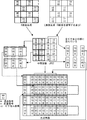
図22は、右眼用(R)画像と左眼用(L)画像を用いて斜めバリア方式の合成画像(立体視用画像)を生成するときの処理内容を示している。なお、各画像においては、R(赤色)画素とG(緑色)画素とB(青色)画素とが並んでおり、例えば、座標「00」の一つのR画素と、座標「00」の一つのG画素と、座標「00」の一つのB画素で、座標「00」の一つの絵素(ピクセル)が構成される。この処理では、画素単位で右眼画像と左眼画像から交互に画素を取り出して並べることで合成画像を得ている。また、図23は、合成画像から中間画像を生成する従来の処理を示している。
しかしながら、図23に示す中間画像では、右眼画素が集結されると共に左眼画素が集結されていることから、合成画像をそのまま圧縮するのに比べれば画質の劣化は少ないものの、中間画像において隣接する絵素は、元の視点画像上では斜めに並ぶ絵素同士であるため、かかる中間画像の圧縮では画質の劣化を十分に防止することはできない。 However, in the intermediate image shown in FIG. 23, since the right eye pixels are collected and the left eye pixels are gathered, although there is less degradation in image quality than when the synthesized image is compressed as it is, it is adjacent in the intermediate image. Since the picture elements to be processed are picture elements arranged obliquely on the original viewpoint image, the compression of the intermediate image cannot sufficiently prevent the deterioration of the image quality.
この発明は、上記の事情に鑑み、符号化処理(圧縮)を行うのに好適な中間画像(処理用画像)を得ることが可能となる画像生成方法を提供することを目的とする。 In view of the above circumstances, an object of the present invention is to provide an image generation method capable of obtaining an intermediate image (processing image) suitable for performing encoding processing (compression).
この発明の画像生成方法は、上記の課題を解決するために、N個(Nは二以上の整数)の視点画像を用いて斜めバリア方式の立体視用画像を生成することに利用できる画像生成方法であって、各視点画像内で斜めにずれた形態で且つ各々の絵素が水平方向及び垂直方向に並ぶN個のサブ視点画像を抽出することを特徴とする。かかる構成であれば、各視点画像についてN個のサブ視点画像を抽出しており、これらN個のサブ視点画像を用いて例えば中間画像や立体視用画像を生成することができる。 In order to solve the above-described problem, the image generation method of the present invention can be used to generate an oblique barrier-type stereoscopic image using N (N is an integer of 2 or more) viewpoint images. A method is characterized in that N sub-viewpoint images are extracted in a form that is obliquely shifted in each viewpoint image and each picture element is arranged in the horizontal direction and the vertical direction. With this configuration, N sub-viewpoint images are extracted for each viewpoint image, and for example, an intermediate image or a stereoscopic image can be generated using these N sub-viewpoint images.
また、この発明の画像生成方法は、N個(Nは二以上の整数)の視点画像を用い、斜めバリア方式の立体視用画像の生成に利用できる中間画像を生成する画像生成方法であって、各視点画像内で斜めにずれた形態で且つ各々の絵素が水平方向及び垂直方向に並ぶN個のサブ視点画像を抽出し、各サブ視点画像を構成している絵素の水平方向の並び及び垂直方向の並びを保持しつつこれら絵素を集結させた中間画像を生成することを特徴とする。各サブ視点画像内の各絵素を構成している複数の色画素の全てを用いて中間画像を生成してもよい。 The image generation method of the present invention is an image generation method for generating an intermediate image that can be used for generating an oblique barrier type stereoscopic image using N (N is an integer of 2 or more) viewpoint images. , N sub-viewpoint images that are obliquely shifted in each viewpoint image and in which each picture element is arranged in the horizontal direction and the vertical direction are extracted, and the horizontal direction of the picture elements constituting each sub-viewpoint image is extracted. An intermediate image in which these picture elements are gathered is generated while maintaining the alignment and the vertical alignment. An intermediate image may be generated using all of a plurality of color pixels constituting each picture element in each sub-viewpoint image.
これらの画像生成方法において、各視点画像をコンピュータグラフィックス技術を用いて作成すると共に、各視点画像に対し、カメラ座標系のビューポイントを中心とした回転処理、ビューボリュームの移動、ビューポート変換時の原点の移動、の少なくとも一つの処理を行うことでサブ視点画像を生成するようにしてもよい。 In these image generation methods, each viewpoint image is created using computer graphics technology, and for each viewpoint image, rotation processing around the viewpoint of the camera coordinate system, movement of the view volume, and viewport conversion are performed. The sub-viewpoint image may be generated by performing at least one process of moving the origin.
また、この発明の画像生成方法は、N個(Nは二以上の整数)の視点画像に基づいて生成された斜めバリア方式の立体視用画像から各視点画像を抽出すると共に、各視点画像内で色画素の配置が一致する絵素が水平方向及び垂直方向に並ぶサブ視点画像をN個抽出し、各サブ視点画像を構成している絵素の水平方向の並び及び垂直方向の並びを保持しつつこれら絵素を集結させた中間画像を生成することを特徴とする。 In addition, the image generation method of the present invention extracts each viewpoint image from the oblique barrier type stereoscopic image generated based on N (N is an integer of 2 or more) viewpoint images, Extracts N sub-viewpoint images in which pixel elements with the same color pixel arrangement are aligned in the horizontal and vertical directions, and maintains the horizontal and vertical alignments of the picture elements that make up each sub-viewpoint image However, an intermediate image in which these picture elements are gathered is generated.
これら構成の構成であれば、中間画像を構成する絵素は視点画像における水平方向及び垂直方向に並ぶ絵素の当該並びの関係を保ったものとなり、絵素同士の相関性は高く、圧縮処理に適したものとなる。各サブ視点画像から得られるN個の中間画像を集結させた全体中間画像も圧縮処理に適す。中間画像又は全体中間画像を圧縮してもよい。 With these configurations, the picture elements that make up the intermediate image maintain the relationship between the picture elements arranged in the horizontal and vertical directions in the viewpoint image, and the correlation between the picture elements is high, and compression processing is performed. It will be suitable for. An entire intermediate image obtained by collecting N intermediate images obtained from each sub-viewpoint image is also suitable for the compression process. The intermediate image or the entire intermediate image may be compressed.
以上説明したように、この発明によれば、斜めバリア方式に利用される視点画像或いは立体視用画像について絵素が水平及び垂直方向に整列するサブ視点画像に注目することにより、符号化処理(圧縮)を行っても画質の劣化を少なくできる中間画像の生成が可能になるという効果を奏する。 As described above, according to the present invention, by focusing on the sub-viewpoint image in which the picture elements are aligned in the horizontal and vertical directions for the viewpoint image or the stereoscopic image used in the oblique barrier method, the encoding process ( Even if compression is performed, it is possible to generate an intermediate image that can reduce image quality degradation.
以下、この発明の実施形態の画像生成方法を図1乃至図20に基づいて説明していく。 Hereinafter, an image generation method according to an embodiment of the present invention will be described with reference to FIGS.
図1(a)は2眼斜めバリア方式の画素配列(立体視用画像)を示している。図中の「1」は第1視点画像であり、「2」は第2視点画像である。Rは赤色の画素(又は赤色データ)、Gは緑色の画素(又は緑色データ)、Bは青色の画素(又は、青色データ)である。斜めバリア方式では、同一視点の画素は斜め方向に並ぶ。 FIG. 1A shows a pixel arrangement (stereoscopic image) of a two-eye oblique barrier method. In the figure, “1” is the first viewpoint image, and “2” is the second viewpoint image. R is a red pixel (or red data), G is a green pixel (or green data), and B is a blue pixel (or blue data). In the oblique barrier method, pixels from the same viewpoint are arranged in an oblique direction.
図1(b)は、前記立体視用画像のなかで第1視点画像のみを抽出して示している。図中の各太実線枠内及び各太点線枠内には、R,G,Bが存在する。一纏まりのR,G,Bを絵素という。各太実線枠(絵素)は、R,G,Bの並び(配置)が一致しており、且つ、垂直方向及び水平方向に並んでいる。同様に、各太点線枠(絵素)は、R,G,Bの並び(配置)が一致しており、且つ、垂直方向及び水平方向に並んでいる。上記立体視用画像からは、太実線枠(絵素)のグループによるサブ視点画像と、太点線枠(絵素)のグループによるサブ視点画像とを生成することができる。すなわち、視点数が2であるので、2つのサブ視点画像が生成される。 FIG. 1B shows only the first viewpoint image extracted from the stereoscopic image. R, G, and B exist in each thick solid line frame and each thick dotted line frame in the figure. A group of R, G, and B is called a picture element. The thick solid line frames (picture elements) have the same arrangement (arrangement) of R, G, and B, and are arranged in the vertical direction and the horizontal direction. Similarly, the thick dotted line frames (picture elements) have the same arrangement (arrangement) of R, G, and B, and are arranged in the vertical direction and the horizontal direction. From the stereoscopic image, it is possible to generate a sub-viewpoint image by a group of thick solid line frames (picture elements) and a sub-viewpoint image by a group of thick dotted line frames (picture elements). That is, since the number of viewpoints is 2, two sub-viewpoint images are generated.
図1(c)は、サブ視点画像抽出の他の例を示している。図の各太実線枠内及び各太点線枠内には、R,G,Bが存在する。各太実線枠(絵素)は、R,G,Bの並び(配置)が一致しており、且つ、垂直方向及び水平方向に並んでいる。同様に、各太点線枠(絵素)は、R,G,Bの並び(配置)が一致しており、且つ、垂直方向及び水平方向に並んでいる。 FIG. 1C shows another example of sub-viewpoint image extraction. R, G, and B exist in each thick solid line frame and each thick dotted line frame in the figure. The thick solid line frames (picture elements) have the same arrangement (arrangement) of R, G, and B, and are arranged in the vertical direction and the horizontal direction. Similarly, the thick dotted line frames (picture elements) have the same arrangement (arrangement) of R, G, and B, and are arranged in the vertical direction and the horizontal direction.
視点が異なる複数の視点画像は、例えば互いに眼間距離離して設けた複数のカメラにて被写体を撮像することにより得ることができる。また、コンピュータグラフィックス技術により、ポリゴン画像の3次元映像に対して複数の視線方向を設定して各々平面投影することでも視点が異なる複数の2次元映像データを得ることができる。 A plurality of viewpoint images with different viewpoints can be obtained, for example, by imaging a subject with a plurality of cameras provided at a distance between eyes. In addition, a plurality of 2D video data having different viewpoints can be obtained by setting a plurality of line-of-sight directions to a 3D image of a polygon image and projecting the respective planes by computer graphics technology.
図2は右眼用(R)画像と左眼用(L)画像とを生成し、これら二視点画像から中間画像を生成し、この中間画像から合成画像(立体視用画像)を生成する処理を示した説明図である。図において、各絵素又は画素の上段側の2つの数字列(m,n)において、mは視点番号であり、nは配置番号(サブ視点画像番号)である。また、下段側の2つの数字列(x,y)は絵素又は画素の座標である。両画像はそれぞれ市松模様状に絵素が抽出されており、両視点画像の絵素の配置は補間関係にある。右眼用画像を例にとると、太実線枠は第1サブ視点画像となり、太点線枠は第2サブ視点画像となる。左眼用画像でも同様に第1サブ視点画像と第2サブ視点画像が存在する。 FIG. 2 shows a process for generating a right-eye (R) image and a left-eye (L) image, generating an intermediate image from these two viewpoint images, and generating a composite image (stereoscopic image) from the intermediate image. It is explanatory drawing which showed. In the figure, in two numerical strings (m, n) on the upper side of each picture element or pixel, m is a viewpoint number, and n is an arrangement number (sub-viewpoint image number). Further, the two numeric strings (x, y) on the lower side are the coordinates of the picture element or pixel. In both images, picture elements are extracted in a checkered pattern, and the arrangement of picture elements in both viewpoint images is in an interpolating relationship. Taking the right eye image as an example, the thick solid line frame is the first sub-viewpoint image, and the thick dotted line frame is the second sub-viewpoint image. Similarly, the first sub-viewpoint image and the second sub-viewpoint image exist in the left-eye image.
中間画像では、各サブ視点画像を構成する絵素を、垂直方向及び水平方向の並びの関係を維持しつつ集結させている。更に、これら4つの中間画像を集結させて1枚の画像(全体中間画像)を生成することとしてもよい。中間画像や全体中間画像を用いて符号化処理(圧縮)を行うのがよい。両サブ視点画像の絵素における画素は横方向にR,B,Gの順に並んでいる。 In the intermediate image, the picture elements constituting each sub-viewpoint image are gathered while maintaining the vertical and horizontal alignment relationships. Further, these four intermediate images may be collected to generate one image (entire intermediate image). It is preferable to perform encoding processing (compression) using the intermediate image or the entire intermediate image. Pixels in the picture elements of both sub-viewpoint images are arranged in the order of R, B, and G in the horizontal direction.
合成画像では、各サブ視点画像の絵素における画素は水平方向に1画素おきに配置され、水平方向にR,B,Gの順に並んでいる。また、合成画素では、両視点画像における第1サブ視点画像のみで水平1ラインの画像が形成され、その下の水平1ラインは両視点画像における第2サブ視点画像のみで構成される。なお、図2では、合成画像において、視点画像、サブ視点画像の全てでRGBの並ぶ順番が同じになる。また、合成画像における端側の空白部分は画素抜け(データ不存在)部分である。 In the composite image, the pixels in the picture elements of each sub-viewpoint image are arranged every other pixel in the horizontal direction, and are arranged in the order of R, B, and G in the horizontal direction. In the synthesized pixel, an image of one horizontal line is formed only from the first sub-viewpoint image in both viewpoint images, and the horizontal one line below is composed of only the second sub-viewpoint image in both viewpoint images. In FIG. 2, in the synthesized image, the order in which RGB are arranged is the same in all of the viewpoint image and the sub-viewpoint image. In addition, the blank portion on the end side in the composite image is a pixel missing (data nonexistent) portion.
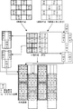
図3は右眼用(R)画像と左眼用(L)画像とを生成し、これら二視点画像から中間画像を生成し、この中間画像から合成画像(立体視用画像)を生成する他の処理例を示した説明図である。両画像はそれぞれ市松模様状に絵素が抽出されており、両画像の絵素の配置は同じ(非補間関係)である。右眼用画像を例にとると、実線枠は第1サブ視点画像となり、点線枠は第2サブ視点画像となる。左眼用画像でも同様に第1サブ視点画像と第2サブ視点画像が存在する。 FIG. 3 generates a right eye (R) image and a left eye (L) image, generates an intermediate image from these two viewpoint images, and generates a composite image (stereoscopic image) from the intermediate image. It is explanatory drawing which showed the example of a process. In both images, picture elements are extracted in a checkered pattern, and the arrangement of the picture elements in both images is the same (non-interpolation relationship). Taking the image for the right eye as an example, the solid line frame becomes the first sub-viewpoint image, and the dotted line frame becomes the second sub-viewpoint image. Similarly, the first sub-viewpoint image and the second sub-viewpoint image exist in the left-eye image.
中間画像では、各サブ視点画像を構成する絵素を、垂直方向及び水平方向の並びの関係を維持しつつ集結させている。更に、これら4つの中間画像を集結させて1枚の画像(全体中間画像)を生成することとしてもよい。中間画像や全体中間画像を用いて符号化処理(圧縮)を行うのがよい。 In the intermediate image, the picture elements constituting each sub-viewpoint image are gathered while maintaining the vertical and horizontal alignment relationships. Further, these four intermediate images may be collected to generate one image (entire intermediate image). It is preferable to perform encoding processing (compression) using the intermediate image or the entire intermediate image.
合成画像の右眼用画像については、そのサブ視点画像における絵素の画素は水平方向にR,B,Gの順に並んでいるが、左眼用画像については、そのサブ視点画像における絵素の画素は水平方向にG,R,Bの順に並んでいる。また、合成画像では、各サブ視点画像における絵素の画素は水平方向に1画素おきに配置され、水平方向にR,B,G又はG,R,Bの順に並んでいる。また、合成画像では、両視点画像における第1サブ視点画像のみで水平1ラインの画像が形成され、その下の水平1ラインは両視点画像における第2サブ視点画像のみで構成される。なお、図3では、合成画像において、視点画像のRGBの並ぶ順番が同じになる。また、合成画像における端側の空白部分は画素抜け(データ不存在)部分である。 For the right-eye image of the composite image, the pixel elements in the sub-viewpoint image are arranged in the order of R, B, and G in the horizontal direction. For the left-eye image, the pixel elements in the sub-viewpoint image are arranged. The pixels are arranged in the order of G, R, and B in the horizontal direction. Further, in the composite image, the pixels of the picture elements in each sub-viewpoint image are arranged every other pixel in the horizontal direction, and are arranged in the order of R, B, G or G, R, B in the horizontal direction. Further, in the composite image, an image of one horizontal line is formed only from the first sub-viewpoint image in both viewpoint images, and the horizontal one line below is composed of only the second sub-viewpoint image in both viewpoint images. In FIG. 3, the order of RGB in the viewpoint image is the same in the composite image. In addition, the blank portion on the end side in the composite image is a pixel missing (data nonexistent) portion.
図4は右眼用(R)画像と左眼用(L)画像とを生成し、これら二視点画像から中間画像を生成し、この中間画像から合成画像(立体視用画像)を生成する他の処理例を示した説明図である。両画像はそれぞれ市松模様状に絵素が抽出されており、両画像の絵素の配置は補間関係にある。右眼用画像を例にとると、実線枠は第1サブ視点画像となり、点線枠は第2サブ視点画像となる。左眼用画像でも同様に第1サブ視点画像と第2サブ視点画像が存在する。 FIG. 4 shows another example of generating a right-eye (R) image and a left-eye (L) image, generating an intermediate image from these two viewpoint images, and generating a composite image (stereoscopic image) from the intermediate image. It is explanatory drawing which showed the example of a process. In both images, picture elements are extracted in a checkered pattern, and the arrangement of picture elements in both images is in an interpolating relationship. Taking the image for the right eye as an example, the solid line frame becomes the first sub-viewpoint image, and the dotted line frame becomes the second sub-viewpoint image. Similarly, the first sub-viewpoint image and the second sub-viewpoint image exist in the left-eye image.
中間画像では、各サブ視点画像を構成する絵素を、垂直方向及び水平方向の並びの関係を維持しつつ集結させている。更に、これら4つの中間画像を集結させて1枚の画像(全体中間画像)を生成することとしてもよい。中間画像や全体中間画像を用いて符号化処理(圧縮)を行うのがよい。 In the intermediate image, the picture elements constituting each sub-viewpoint image are gathered while maintaining the vertical and horizontal alignment relationships. Further, these four intermediate images may be collected to generate one image (entire intermediate image). It is preferable to perform encoding processing (compression) using the intermediate image or the entire intermediate image.
合成画像では、両サブ視点画像における絵素の画素は水平方向にR,G,Bの順でV字状に配置される。すなわち、R,G,Bの画素のうちのG画素を1画素だけ下に移動させている。また、合成画像では、右眼用画像における第1サブ視点画像と左眼用画像における第2サブ視点画像で垂直方向絵素ラインが形成され、その横に位置する垂直方向絵素ラインは右眼用画像における第2サブ視点画像と左眼用画像における第1サブ視点画像で構成される。なお、図4では、合成画像において、視点画像、サブ視点画像の全てでRGBの並ぶ順番が同じになる。また、合成画像における端側の空白部分は画素抜け(データ不存在)部分である。 In the composite image, picture element pixels in both sub-viewpoint images are arranged in a V shape in the order of R, G, and B in the horizontal direction. That is, the G pixel among the R, G, and B pixels is moved downward by one pixel. In the composite image, a vertical pixel line is formed by the first sub-viewpoint image in the right-eye image and the second sub-viewpoint image in the left-eye image, and the vertical pixel line located next to the first sub-viewpoint image is the right-eye image. A second sub-viewpoint image in the image for use and a first sub-viewpoint image in the image for the left eye. In FIG. 4, in the synthesized image, the order in which RGB are arranged is the same in all of the viewpoint image and the sub-viewpoint image. In addition, the blank portion on the end side in the composite image is a pixel missing (data nonexistent) portion.
図5は右眼用(R)画像と左眼用(L)画像とを生成し、これら二視点画像から中間画像を生成し、この中間画像から合成画像(立体視用画像)を生成する他の処理例を示した説明図である。両画像はそれぞれ市松模様状に絵素が抽出されており、両画像の絵素の配置は同じ(非補間関係)である。右眼用画像を例にとると、実線枠は第1サブ視点画像となり、点線枠は第2サブ視点画像となる。左眼用画像でも同様に第1サブ視点画像と第2サブ視点画像が存在する。 FIG. 5 shows another example of generating a right-eye (R) image and a left-eye (L) image, generating an intermediate image from these two viewpoint images, and generating a composite image (stereoscopic image) from the intermediate image. It is explanatory drawing which showed the example of a process. In both images, picture elements are extracted in a checkered pattern, and the arrangement of the picture elements in both images is the same (non-interpolation relationship). Taking the image for the right eye as an example, the solid line frame becomes the first sub-viewpoint image, and the dotted line frame becomes the second sub-viewpoint image. Similarly, the first sub-viewpoint image and the second sub-viewpoint image exist in the left-eye image.
中間画像では、各サブ視点画像を構成する絵素を、垂直方向及び水平方向の並びの関係を維持しつつ集結させている。更に、これら4つの中間画像を集結させて1枚の画像(全体中間画像)を生成することとしてもよい。中間画像や全体中間画像を用いて符号化処理(圧縮)を行うのがよい。 In the intermediate image, the picture elements constituting each sub-viewpoint image are gathered while maintaining the vertical and horizontal alignment relationships. Further, these four intermediate images may be collected to generate one image (entire intermediate image). It is preferable to perform encoding processing (compression) using the intermediate image or the entire intermediate image.
合成画像では、両サブ視点画像における絵素の画素は水平方向にR,G,Bの順にV字状に配置される。すなわち、R,G,Bの画素のうちのG画素を1画素だけ下に移動させている。一方、左眼用画像の絵素における画素はΛ字状に配置される。すなわち、R,G,Bの画素のうちのG画素を1画素だけ上に移動させている。また、合成画像では、右眼用画像における第1サブ視点画像と左眼用画像における第1サブ視点画像で垂直方向絵素ラインが形成され、その横に位置する垂直方向絵素ラインは右眼用画像における第2サブ視点画像と左眼用画像における第2サブ視点画像で構成される。なお、図5では、合成画像において、視点画像のRGBの並ぶ順番が同じになる。合成画像における端側の空白部分は画素抜け(データ不存在)部分である。 In the composite image, picture element pixels in both sub-viewpoint images are arranged in a V shape in the order of R, G, and B in the horizontal direction. That is, the G pixel among the R, G, and B pixels is moved downward by one pixel. On the other hand, the pixels in the picture element of the left-eye image are arranged in a Λ shape. That is, the G pixel of the R, G, and B pixels is moved up by one pixel. In the synthesized image, a vertical pixel line is formed by the first sub-viewpoint image in the right-eye image and the first sub-viewpoint image in the left-eye image, and the vertical pixel line located next to the first sub-viewpoint image is the right-eye image. A second sub-viewpoint image in the image for use and a second sub-viewpoint image in the image for the left eye. In FIG. 5, the order of RGB in the viewpoint image is the same in the composite image. The blank portion on the end side in the composite image is a pixel missing portion (data does not exist).
上述した処理によって生成された合成画像(立体視用画像)のファイルには、例えば、視点数情報、サブ視点画像の並びに関する情報(画素の色についての並び、絵素(画素)の座標についての並び、横方向に一つおきに画素を配置、V字状に配置、Λ字状に配置といった情報)を与えておくのがよい。或いは、単に、第1方式、第2方式といった情報を与えておき、画像処理装置(ソフトウェア)において、各方式の内容を保持しておくこととしてもよい。 The file of the composite image (stereoscopic image) generated by the above-described processing includes, for example, information on the number of viewpoints, information on the arrangement of the sub-viewpoint images (arrangement about pixel colors, coordinates of picture elements (pixels)). It is preferable to give information such as arranging every other pixel in the horizontal direction, arranging in a V shape, and arranging in a Λ shape. Alternatively, information such as the first method and the second method may be simply given, and the contents of each method may be held in the image processing apparatus (software).
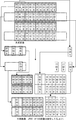
図6は合成画像(立体視用画像)から中間画像を生成する処理例を示した説明図である。図6では、RGBの並ぶ順番が同じになるように各視点画像、サブ視点画像の絵素を選択する。図において、各絵素又は画素の上段側の2つの数字列(m,n)において、mは視点番号であり、nは配置番号(サブ画像番号)である。また、下段側の2つの数字列(x,y)は絵素又は画素の座標である。画像処理装置(ソフトウェア)は、合成画像(立体視用画像)のファイルに記録されている情報に基づいて、例えば、視点数情報、サブ視点画像の並びに関する情報(画素の色についての並び、絵素(画素)の座標についての並び、横方向に一つおきに画素を配置、V字状に配置、Λ字状に配置といった情報)を知得する。図6に示す処理例では、画像処理装置(ソフトウェア)は、合成画像について、奇数番目の水平ラインは右眼画像の第1サブ視点画像の画素と左眼画像の第1サブ視点画像の画素とが交互に配置されていることを知得し、右眼画像の第1サブ視点画像の絵素(同一座標を持つもの)と左眼画像の第1サブ視点画像の絵素(同一座標を持つもの)とを抽出する。同様に、合成画像について、偶数番目の水平ラインは右眼画像の第2サブ視点画像の画素と左眼画像の第2サブ視点画像の画素とが交互に配置されていることを知得し、右眼画像の第2サブ視点画像の絵素(同一座標を持つもの)と左眼画像の第2サブ視点画像の絵素(同一座標を持つもの)とを抽出する。更に、画像処理装置(ソフトウェア)は、合成画像から抽出した絵素(同一座標を持つもの)は、画素の並びがR,B,Gになっていることを知得し、中間画像の各視点画像においてR,G,Bの並びとなるように処理する。そして、各サブ視点画像の絵素群を、垂直方向及び水平方向の並びの関係を維持しつつ集結させることにより、中間画像を得る。4つのサブ視点画像から成る中間画像は結合されて一枚の画像(全体中間画像)として扱うようにしてもよい。以下の処理例においても同様である。中間画像や全体中間画像に対して符号化処理(圧縮)を行うのがよい。 FIG. 6 is an explanatory diagram showing a processing example for generating an intermediate image from a composite image (stereoscopic image). In FIG. 6, the picture elements of each viewpoint image and sub-viewpoint image are selected so that the order in which RGB are arranged is the same. In the figure, in two numerical strings (m, n) on the upper side of each picture element or pixel, m is a viewpoint number, and n is an arrangement number (sub-image number). Further, the two numeric strings (x, y) on the lower side are the coordinates of the picture element or pixel. Based on the information recorded in the composite image (stereoscopic image) file, the image processing device (software), for example, information on the number of viewpoints, information on the arrangement of the sub-viewpoint images (arrangement of pixel colors, pictures The information about the arrangement of the coordinates of the elements (pixels), every other pixel in the horizontal direction, the arrangement in a V shape, the arrangement in a Λ shape, etc. is obtained. In the processing example illustrated in FIG. 6, the image processing apparatus (software) has an odd-numbered horizontal line for the synthesized image, the pixel of the first sub-viewpoint image of the right-eye image and the pixel of the first sub-viewpoint image of the left-eye image. Are alternately arranged, and the picture element of the first sub-viewpoint image of the right-eye image (having the same coordinates) and the picture element of the first sub-viewpoint image of the left-eye image (having the same coordinates) Stuff). Similarly, with respect to the composite image, the even-numbered horizontal line knows that the pixels of the second sub-viewpoint image of the right-eye image and the pixels of the second sub-viewpoint image of the left-eye image are alternately arranged, A picture element (having the same coordinates) of the second sub-viewpoint image of the right-eye image and a picture element (having the same coordinates) of the second sub-viewpoint image of the left-eye image are extracted. Further, the image processing apparatus (software) knows that the picture elements extracted from the composite image (having the same coordinates) have the pixel arrangement of R, B, and G, and each viewpoint of the intermediate image Processing is performed so that R, G, and B are arranged in the image. Then, an intermediate image is obtained by collecting the pixel groups of each sub-viewpoint image while maintaining the vertical and horizontal alignment relationships. The intermediate images composed of the four sub-viewpoint images may be combined and handled as one image (entire intermediate image). The same applies to the following processing examples. It is preferable to perform encoding processing (compression) on the intermediate image or the entire intermediate image.
図7は合成画像(立体視用画像)から中間画像を生成する他の処理例を示した説明図である。図7では、合成画像の各視点画像のRGBの並びは同じである。画像処理装置(ソフトウェア)は、合成画像(立体視用画像)のファイルから各種情報を知得する。図7の処理例では、画像処理装置(ソフトウェア)は、合成画像について、奇数番目の水平ラインは右眼画像の第1サブ視点画像の画素と左眼画像の第1サブ視点画像の画素とが交互に配置されていることを知得し、右眼画像の第1サブ視点画像の絵素(同一座標を持つもの)と左眼画像の第1サブ視点画像の絵素(同一座標を持つもの)とを抽出する。同様に、合成画像について、偶数番目の水平ラインは右眼画像の第2サブ視点画像の画素と左眼画像の第2サブ視点画像の画素とが交互に配置されていることを知得し、右眼画像の第2サブ視点画像の絵素(同一座標を持つもの)と左眼画像の第2サブ視点画像の絵素(同一座標を持つもの)とを抽出する。更に、画像処理装置(ソフトウェア)は、合成画像から抽出した絵素(同一座標を持つもの)は、右眼画像については画素の並びがR,B,Gになり、左眼画像については画素の並びがG,R,Bになっていることを知得し、中間画像の各視点画像上でR,G,Bの並びとなるようにそれぞれ処理する。そして、各サブ視点画像の絵素群を、垂直方向及び水平方向の並びの関係を維持しつつ集結させることにより、中間画像を得る。 FIG. 7 is an explanatory diagram showing another example of processing for generating an intermediate image from a composite image (stereoscopic image). In FIG. 7, the arrangement of RGB of the viewpoint images of the composite image is the same. The image processing apparatus (software) obtains various information from the file of the composite image (stereoscopic image). In the processing example of FIG. 7, the image processing apparatus (software) of the composite image has odd-numbered horizontal lines that include pixels of the first sub-viewpoint image of the right-eye image and pixels of the first sub-viewpoint image of the left-eye image. Knowing that they are arranged alternately, the first sub-viewpoint image element of the right eye image (having the same coordinates) and the first sub-viewpoint image element of the left eye image (having the same coordinates) ) And extract. Similarly, with respect to the composite image, the even-numbered horizontal line knows that the pixels of the second sub-viewpoint image of the right-eye image and the pixels of the second sub-viewpoint image of the left-eye image are alternately arranged, A picture element (having the same coordinates) of the second sub-viewpoint image of the right-eye image and a picture element (having the same coordinates) of the second sub-viewpoint image of the left-eye image are extracted. Further, the image processing apparatus (software) has the pixel arrangement extracted from the composite image (having the same coordinates) with the pixel arrangement of R, B, and G for the right eye image and the pixel arrangement for the left eye image. It is known that the arrangement is G, R, B, and processing is performed so that the arrangement is R, G, B on each viewpoint image of the intermediate image. Then, an intermediate image is obtained by collecting the pixel groups of each sub-viewpoint image while maintaining the vertical and horizontal alignment relationships.
なお、図7の例では、合成画像において、左端(右端)には使用しない領域が存在するので、ダミー画素列を追加してもよい。或いは、前述の図6の例のように、サブ視点画像を大きくとってもよい。 In the example of FIG. 7, since there is an unused area at the left end (right end) in the composite image, a dummy pixel column may be added. Alternatively, as in the example of FIG. 6 described above, the sub-viewpoint image may be enlarged.
図8は合成画像(立体視用画像)から中間画像を生成する他の処理例を示した説明図である。図8では、合成画像のサブ視点画像間でRGBの並びが異なる。画像処理装置(ソフトウェア)は、合成画像(立体視用画像)のファイルから各種情報を知得する。図8の処理例においては、画像処理装置(ソフトウェア)は、合成画像について、奇数番目の水平ラインは右眼画像の第1サブ視点画像の画素と左眼画像の第1サブ視点画像の画素とが交互に配置されていることを知得し、右眼画像の第1サブ視点画像の絵素(同一座標を持つもの)と左眼画像の第1サブ視点画像の絵素(同一座標を持つもの)とを抽出する。同様に、合成画像について、偶数番目の水平ラインは右眼画像の第2サブ視点画像の画素と左眼画像の第2サブ視点画像の画素とが交互に配置されていることを知得し、右眼画像の第2サブ視点画像の絵素(同一座標を持つもの)と左眼画像の第2サブ視点画像の絵素(同一座標を持つもの)とを抽出する。更に、画像処理装置(ソフトウェア)は、合成画像から抽出した絵素(同一座標を持つもの)は、右眼画像の第1視点画像と左眼画像の第2視点画像については画素の並びがR,B,Gになり、右眼画像の第2視点画像と左眼画像の第1視点画像については画素の並びがG,R,Bになることを知得し、中間画像の各視点画像上でR,G,Bの並びとなるようにそれぞれ処理する。そして、各サブ視点画像の絵素群を、垂直方向及び水平方向の並びの関係を維持しつつ集結させることにより、中間画像を得る。 FIG. 8 is an explanatory diagram showing another example of processing for generating an intermediate image from a composite image (stereoscopic image). In FIG. 8, the arrangement of RGB differs between the sub-viewpoint images of the composite image. The image processing apparatus (software) obtains various information from the file of the composite image (stereoscopic image). In the processing example of FIG. 8, the image processing apparatus (software) has the odd-numbered horizontal lines of the composite image and the pixels of the first sub-viewpoint image of the right eye image and the pixels of the first sub-viewpoint image of the left eye image. Are alternately arranged, and the picture element of the first sub-viewpoint image of the right-eye image (having the same coordinates) and the picture element of the first sub-viewpoint image of the left-eye image (having the same coordinates) Stuff). Similarly, with respect to the composite image, the even-numbered horizontal line knows that the pixels of the second sub-viewpoint image of the right-eye image and the pixels of the second sub-viewpoint image of the left-eye image are alternately arranged, A picture element (having the same coordinates) of the second sub-viewpoint image of the right-eye image and a picture element (having the same coordinates) of the second sub-viewpoint image of the left-eye image are extracted. Further, the image processing apparatus (software) has a pixel arrangement (with the same coordinates) extracted from the composite image in which the pixel arrangement is R for the first viewpoint image of the right eye image and the second viewpoint image of the left eye image. , B, and G, the second viewpoint image of the right eye image and the first viewpoint image of the left eye image know that the pixel arrangement is G, R, and B. Are processed so as to form an array of R, G, and B respectively. Then, an intermediate image is obtained by collecting the pixel groups of each sub-viewpoint image while maintaining the vertical and horizontal alignment relationships.
図9は合成画像(立体視用画像)から中間画像を生成する他の処理例を示した説明図である。図9では、RGBの並ぶ順番が同じになるように各視点画像、サブ視点画像の絵素を選択する。画像処理装置(ソフトウェア)は、合成画像(立体視用画像)のファイルから各種情報を知得する。図9の処理例においては、画像処理装置(ソフトウェア)は、合成画像において左眼画像及び右眼画像共に絵素(同一座標を持つもの)がV字状に配置されていることを知得し、V字状に画素を抽出していく。更に、画像処理装置(ソフトウェア)は、合成画像から抽出した絵素(同一座標を持つもの)を、中間画像の各視点画像上でR,G,Bの並びとなるように処理する。そして、各サブ視点画像の絵素群を、垂直方向及び水平方向の並びの関係を維持しつつ集結させることにより、中間画像を得る。 FIG. 9 is an explanatory diagram showing another example of processing for generating an intermediate image from a composite image (stereoscopic image). In FIG. 9, the picture elements of each viewpoint image and sub-viewpoint image are selected so that the order in which RGB are arranged is the same. The image processing apparatus (software) obtains various types of information from the composite image (stereoscopic image) file. In the processing example of FIG. 9, the image processing apparatus (software) knows that the picture elements (those having the same coordinates) are arranged in a V shape in both the left eye image and the right eye image in the composite image. The pixels are extracted in a V shape. Further, the image processing apparatus (software) processes the picture elements (having the same coordinates) extracted from the composite image so that they are arranged in R, G, B on each viewpoint image of the intermediate image. Then, an intermediate image is obtained by collecting the pixel groups of each sub-viewpoint image while maintaining the vertical and horizontal alignment relationships.
図10は合成画像(立体視用画像)から中間画像を生成する他の処理例を示した説明図である。図10では、合成画像の各視点画像のRGBの並びは同じである。画像処理装置(ソフトウェア)は、合成画像(立体視用画像)のファイルから各種情報を知得する。図10の処理例では、画像処理装置(ソフトウェア)は、合成画像において右眼用画像の絵素(同一座標を持つもの)がV字状に配置されていることを知得してV字状に画素を抽出し、左眼用画像の絵素(同一座標を持つもの)がΛ字状に配置されていることを知得してΛ字状に画素を抽出していく。更に、画像処理装置(ソフトウェア)は、合成画像から抽出した絵素(同一座標を持つもの)を、中間画像の各視点画像上でR,G,Bの並びとなるように処理する。そして、各サブ視点画像の絵素群を、垂直方向及び水平方向の並びの関係を維持しつつ集結させることにより、中間画像を得る。 FIG. 10 is an explanatory diagram showing another example of processing for generating an intermediate image from a composite image (stereoscopic image). In FIG. 10, the RGB arrangement of the viewpoint images of the composite image is the same. The image processing apparatus (software) obtains various information from the file of the composite image (stereoscopic image). In the processing example of FIG. 10, the image processing apparatus (software) knows that the picture elements of the right-eye image (those having the same coordinates) are arranged in a V shape in the composite image, and the V shape is obtained. The pixels are extracted to the left eye, and it is learned that the picture elements of the left-eye image (those having the same coordinates) are arranged in a Λ shape, and the pixels are extracted in a Λ shape. Further, the image processing apparatus (software) processes the picture elements (having the same coordinates) extracted from the composite image so that they are arranged in R, G, B on each viewpoint image of the intermediate image. Then, an intermediate image is obtained by collecting the pixel groups of each sub-viewpoint image while maintaining the vertical and horizontal alignment relationships.
図11は合成画像(立体視用画像)から中間画像を生成する他の処理例を示した説明図である。図11では、合成画像のサブ視点画像間でRGBの並びが異なる。画像処理装置(ソフトウェア)は、合成画像(立体視用画像)のファイルから各種情報を知得する。図11の処理例では、画像処理装置(ソフトウェア)は、合成画像において右眼用画像の絵素(同一座標を持つもの)がV字状に配置されているものとΛ状に配置されているものとがあることを知得してV字状又はΛ字状に画素を抽出し、左眼用画像の絵素(同一座標を持つもの)がΛ字状又はV字状に配置されているものとがあることを知得してΛ字状又はV字状に画素を抽出していく。更に、画像処理装置(ソフトウェア)は、合成画像から抽出した絵素(同一座標を持つもの)を、中間画像の各視点画像上でR,G,Bの並びとなるように処理する。そして、各サブ視点画像の絵素群を、垂直方向及び水平方向の並びの関係を維持しつつ集結させることにより、中間画像を得る。 FIG. 11 is an explanatory diagram showing another example of processing for generating an intermediate image from a composite image (stereoscopic image). In FIG. 11, the RGB arrangement differs between the sub-viewpoint images of the composite image. The image processing apparatus (software) obtains various information from the file of the composite image (stereoscopic image). In the processing example of FIG. 11, the image processing apparatus (software) is arranged in a Λ shape with a picture element of the right eye image (having the same coordinates) arranged in a V shape in the composite image. Knowing that there is something, pixels are extracted in a V shape or Λ shape, and the picture elements of the left eye image (those with the same coordinates) are arranged in a Λ shape or V shape Knowing that there is something, extract the pixels in Λ shape or V shape. Further, the image processing apparatus (software) processes the picture elements (having the same coordinates) extracted from the composite image so that they are arranged in R, G, B on each viewpoint image of the intermediate image. Then, an intermediate image is obtained by collecting the pixel groups of each sub-viewpoint image while maintaining the vertical and horizontal alignment relationships.
合成画像(立体視用画像)のファイルから各種情報を知得することは必須では無い。ピクセル間引き合成(図22,図23参照)の画像を用いることもできる。例えば、図23において、合成画像のなかの太実線の絵素(真ん中の画素については、隣接絵素の真ん中の画素と入れ替えて視点を一致させる)は水平方向及び垂直方向に並んでおり、この並びの関係を維持して集結させ、これを第1サブ視点画像とする。また、合成画像のなかの太点線の絵素(真ん中の画素については、隣接絵素の真ん中の画素と入れ替えて視点を一致させる)は水平方向及び垂直方向に並んでおり、この並びの関係を維持して集結させ、これを第2サブ視点画像とする。第1サブ視点画像において各絵素を集結させて中間画像とし、同様に、第2サブ視点画像において各絵素を集結させて中間画像とすればよい。 It is not essential to obtain various types of information from a composite image (stereoscopic image) file. An image of pixel thinning synthesis (see FIGS. 22 and 23) can also be used. For example, in FIG. 23, the thick solid line picture elements in the composite image (the middle pixel is replaced with the middle pixel of the adjacent picture element to match the viewpoint) are arranged in the horizontal and vertical directions. The arrangement is maintained while maintaining the arrangement relationship, and this is used as the first sub-viewpoint image. In addition, the thick dotted line picture elements in the composite image (the middle pixel is replaced with the middle pixel of the adjacent picture element to match the viewpoint) are arranged in the horizontal and vertical directions. This is maintained and collected, and this is used as the second sub-viewpoint image. In the first sub-viewpoint image, the picture elements are gathered to form an intermediate image, and similarly, in the second sub-viewpoint picture, the picture elements are gathered to form an intermediate image.
図12(a)(b)は各視点画像からサブ視点画像を生成する処理を示した説明図である。図12では合成画像のなかの第1視点画像だけを抽出して示している。第1視点画像における第1サブ視点画像は奇数番目の横ラインに対してR,B,G(座標が一致する画素である)の並びで画素を抽出することで実現される。また、第1視点画像における第2サブ視点画像は偶数番目の横ラインに対してR,B,G(座標が一致する画素である)の並びで画素を抽出することで実現される。この考え方は、合成画像における各視点画像のサブ視点画像を抽出する処理及び、実写やコンピュータグラフィックスで生成した各視点画像のサブ視点画像を抽出する処理に適用できる。コンピュータグラフィックスを用いる場合の具体的処理を以下に述べる。 FIGS. 12A and 12B are explanatory diagrams showing processing for generating a sub-viewpoint image from each viewpoint image. FIG. 12 shows only the first viewpoint image extracted from the composite image. The first sub-viewpoint image in the first viewpoint image is realized by extracting pixels in an array of R, B, and G (pixels whose coordinates match) with respect to odd-numbered horizontal lines. In addition, the second sub-viewpoint image in the first viewpoint image is realized by extracting pixels in an array of R, B, and G (pixels having the same coordinates) with respect to even-numbered horizontal lines. This concept can be applied to the process of extracting the sub-viewpoint image of each viewpoint image in the composite image and the process of extracting the sub-viewpoint image of each viewpoint image generated by live action or computer graphics. Specific processing when using computer graphics is described below.
図13(a)(b)はコンピュータグラフィックスのカメラ座標系でビューポイントを回転中心として回転させることで、各視点画像からサブ視点画像を生成する処理を示した説明図である。回転量は絵素のオフセット量(図12参照)と同じ比率で行えばよい。 FIGS. 13A and 13B are explanatory diagrams showing a process of generating a sub-viewpoint image from each viewpoint image by rotating the viewpoint in the computer graphics camera coordinate system as a rotation center. The rotation amount may be performed at the same ratio as the pixel offset amount (see FIG. 12).
図14(a)(b)はコンピュータグラフィックスでビューボリュームを平行移動させることで、各視点画像からサブ視点画像を生成する処理を示した説明図である。原点の平行移動は絵素のオフセット量と同じ比率で行えばよい。 FIGS. 14A and 14B are explanatory diagrams showing processing for generating a sub-viewpoint image from each viewpoint image by translating the view volume by computer graphics. The origin may be translated at the same ratio as the pixel offset.
図15(a)(b)はコンピュータグラフィックスでビューポート変換時に原点の平行移動を行うことで、合成画像を構成している各視点画像からサブ視点画像を生成する処理を示した説明図である。原点の平行移動は絵素のオフセット量と同じ比率で行えばよい。 FIGS. 15A and 15B are explanatory diagrams showing a process of generating a sub-viewpoint image from each viewpoint image constituting a composite image by performing parallel movement of the origin at the time of viewport conversion in computer graphics. is there. The origin may be translated at the same ratio as the pixel offset.
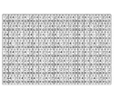
図16は、4視点の合成画像(立体視用映像)の画素配列を示した説明図である。図16中の数値は視点番号を表している。この図において、斜めに並ぶ3つの画素を1絵素として扱う。この場合、各絵素の中心画素が代表点となる。この代表点と各画素との位置関係は行によって異なる。また、各絵素内の画素(R,B,G)の並びがまちまちである。図17は4視点の合成画像のうちの第1視点画像の画素配列を示した説明図である。そして、図18は第1視点画像のうちの第1サブ視点画像の絵素の並びを太線枠で示し、図19は第1視点画像のうちの第2サブ視点画像の絵素の並びを太線枠で示し、図20は第1視点画像のうちの第3サブ視点画像の絵素の並びを太線枠で示し、図21は第1視点画像のうちの第4サブ視点画像の絵素の並びを太線枠で示している。いずれについても、サブ視点画像における絵素は、水平及び垂直方向に整列する。そして、サブ視点画像は互いにずれて存在する。なお、上記の図18乃至図21において、サブ視点画像の絵素数が異なるのは、ものもとサブ画像間で絵素の座標が異なるからであり、実際にはダミー絵素を作るなどして、絵素数を一致させておく方が処理しやすい。画像生成装置では、4つのサブ視点画像の抽出のために4回のレンダリングを行うことになるが、それぞれのレンダリングの画素数は少ないので、処理速度は殆ど低下しない。 FIG. 16 is an explanatory diagram showing a pixel array of a composite image (stereoscopic video) of four viewpoints. The numerical values in FIG. 16 represent viewpoint numbers. In this figure, three pixels arranged diagonally are treated as one picture element. In this case, the central pixel of each picture element is a representative point. The positional relationship between the representative point and each pixel differs depending on the row. Also, the arrangement of pixels (R, B, G) in each picture element varies. FIG. 17 is an explanatory diagram showing the pixel arrangement of the first viewpoint image among the four viewpoint composite images. 18 shows the arrangement of the picture elements of the first sub-viewpoint image in the first viewpoint image with a thick line frame, and FIG. 19 shows the arrangement of the picture elements of the second sub-viewpoint image in the first viewpoint image. FIG. 20 shows the arrangement of picture elements of the third sub-viewpoint image in the first viewpoint image with a thick line frame, and FIG. 21 shows the arrangement of picture elements of the fourth sub-viewpoint image in the first viewpoint image. Is indicated by a bold frame. In either case, the picture elements in the sub-viewpoint image are aligned in the horizontal and vertical directions. The sub-viewpoint images are shifted from each other. In FIG. 18 to FIG. 21, the number of picture elements in the sub-viewpoint image is different because the coordinates of the picture elements are different between the sub-images. It is easier to process by matching the number of picture elements. In the image generating apparatus, rendering is performed four times to extract four sub-viewpoint images. However, since the number of pixels for each rendering is small, the processing speed is hardly reduced.
この4視点の場合においても、それぞれのサブ視点画像において絵素を集結させて中間画像を生成するのがよい。また、各視点(4つ)における4つの中間画像を集結させて全体中間画像を生成してもよい。これら中間画像や全体中間画像について符号化処理(圧縮)を行うのがよい。 Even in the case of these four viewpoints, it is preferable to generate an intermediate image by collecting picture elements in each sub-viewpoint image. Alternatively, the entire intermediate image may be generated by collecting four intermediate images at each viewpoint (four). It is preferable to perform an encoding process (compression) on the intermediate image and the entire intermediate image.
R 右画素(右絵素)
L 左画素(左絵素)
R Right pixel (right picture element)
L Left pixel (left picture element)
Claims (7)
Priority Applications (1)
| Application Number | Priority Date | Filing Date | Title |
|---|---|---|---|
| JP2004139022A JP2005321987A (en) | 2004-05-07 | 2004-05-07 | Image formation method |
Applications Claiming Priority (1)
| Application Number | Priority Date | Filing Date | Title |
|---|---|---|---|
| JP2004139022A JP2005321987A (en) | 2004-05-07 | 2004-05-07 | Image formation method |
Publications (1)
| Publication Number | Publication Date |
|---|---|
| JP2005321987A true JP2005321987A (en) | 2005-11-17 |
Family
ID=35469233
Family Applications (1)
| Application Number | Title | Priority Date | Filing Date |
|---|---|---|---|
| JP2004139022A Pending JP2005321987A (en) | 2004-05-07 | 2004-05-07 | Image formation method |
Country Status (1)
| Country | Link |
|---|---|
| JP (1) | JP2005321987A (en) |
-
2004
- 2004-05-07 JP JP2004139022A patent/JP2005321987A/en active Pending
Similar Documents
| Publication | Publication Date | Title |
|---|---|---|
| Muller et al. | Reliability-based generation and view synthesis in layered depth video | |
| JP4476905B2 (en) | Structure of stereoscopic display image data, recording method of stereoscopic display image data, display reproduction method, recording program, and display reproduction program | |
| Smolic et al. | Intermediate view interpolation based on multiview video plus depth for advanced 3D video systems | |
| EP1581012A1 (en) | Three-dimensional video processing method and three-dimensional video display | |
| JP5238429B2 (en) | Stereoscopic image capturing apparatus and stereoscopic image capturing system | |
| JP6644979B2 (en) | Method and device for generating, storing, transmitting, receiving and playing back a depth map by using color components of an image belonging to a three-dimensional video stream | |
| US20150341614A1 (en) | Stereoscopic video encoding device, stereoscopic video decoding device, stereoscopic video encoding method, stereoscopic video decoding method, stereoscopic video encoding program, and stereoscopic video decoding program | |
| JP2008228199A (en) | Three-dimensional image display device, method for displaying three-dimensional image, and structure of three-dimensional image data | |
| CN105872525A (en) | Image processing apparatus and image processing method | |
| KR20070087561A (en) | Lenticular autostereoscopic display and method and associated autostereoscopic image synthesising method | |
| KR20110093828A (en) | Method and system for encoding a 3d image signal, encoded 3d image signal, method and system for decoding a 3d image signal | |
| WO2011061973A1 (en) | Three-dimensional image display device and method of deriving motion vector | |
| KR100748946B1 (en) | Method of processing three-D image | |
| JP4657258B2 (en) | Stereoscopic image display apparatus and method | |
| US20130088485A1 (en) | Method of storing or transmitting auto-stereoscopic images | |
| JP4173684B2 (en) | Stereoscopic image creation device | |
| CN102036085B (en) | Transmitting device, receiving device, and communication system | |
| JP4267364B2 (en) | Stereoscopic image processing method | |
| KR100755020B1 (en) | Both Eyes 3D Camera of YUV Colour System and 3D Image Display and Processing Method Using The Same | |
| JP2005321987A (en) | Image formation method | |
| EP2369850A2 (en) | Super resolution enhancement method for n-view and n-depth multi-view video | |
| KR101114572B1 (en) | Method and apparatus for converting stereoscopic image signals into monoscopic image signals | |
| JP4293945B2 (en) | Image generation method | |
| JP2019096988A (en) | Imaging device, imaging apparatus, image processing method, and program | |
| CN101588514B (en) | Method for processing three dimensional images |