JP2005321727A - Backlight device and color liquid crystal display - Google Patents
Backlight device and color liquid crystal display Download PDFInfo
- Publication number
- JP2005321727A JP2005321727A JP2004141568A JP2004141568A JP2005321727A JP 2005321727 A JP2005321727 A JP 2005321727A JP 2004141568 A JP2004141568 A JP 2004141568A JP 2004141568 A JP2004141568 A JP 2004141568A JP 2005321727 A JP2005321727 A JP 2005321727A
- Authority
- JP
- Japan
- Prior art keywords
- light emitting
- emitting diode
- light
- color
- liquid crystal
- Prior art date
- Legal status (The legal status is an assumption and is not a legal conclusion. Google has not performed a legal analysis and makes no representation as to the accuracy of the status listed.)
- Pending
Links
Images


Classifications
-
- G—PHYSICS
- G09—EDUCATION; CRYPTOGRAPHY; DISPLAY; ADVERTISING; SEALS
- G09G—ARRANGEMENTS OR CIRCUITS FOR CONTROL OF INDICATING DEVICES USING STATIC MEANS TO PRESENT VARIABLE INFORMATION
- G09G3/00—Control arrangements or circuits, of interest only in connection with visual indicators other than cathode-ray tubes
- G09G3/20—Control arrangements or circuits, of interest only in connection with visual indicators other than cathode-ray tubes for presentation of an assembly of a number of characters, e.g. a page, by composing the assembly by combination of individual elements arranged in a matrix no fixed position being assigned to or needed to be assigned to the individual characters or partial characters
- G09G3/34—Control arrangements or circuits, of interest only in connection with visual indicators other than cathode-ray tubes for presentation of an assembly of a number of characters, e.g. a page, by composing the assembly by combination of individual elements arranged in a matrix no fixed position being assigned to or needed to be assigned to the individual characters or partial characters by control of light from an independent source
- G09G3/3406—Control of illumination source
- G09G3/3413—Details of control of colour illumination sources
-
- G—PHYSICS
- G02—OPTICS
- G02F—OPTICAL DEVICES OR ARRANGEMENTS FOR THE CONTROL OF LIGHT BY MODIFICATION OF THE OPTICAL PROPERTIES OF THE MEDIA OF THE ELEMENTS INVOLVED THEREIN; NON-LINEAR OPTICS; FREQUENCY-CHANGING OF LIGHT; OPTICAL LOGIC ELEMENTS; OPTICAL ANALOGUE/DIGITAL CONVERTERS
- G02F1/00—Devices or arrangements for the control of the intensity, colour, phase, polarisation or direction of light arriving from an independent light source, e.g. switching, gating or modulating; Non-linear optics
- G02F1/01—Devices or arrangements for the control of the intensity, colour, phase, polarisation or direction of light arriving from an independent light source, e.g. switching, gating or modulating; Non-linear optics for the control of the intensity, phase, polarisation or colour
- G02F1/13—Devices or arrangements for the control of the intensity, colour, phase, polarisation or direction of light arriving from an independent light source, e.g. switching, gating or modulating; Non-linear optics for the control of the intensity, phase, polarisation or colour based on liquid crystals, e.g. single liquid crystal display cells
- G02F1/133—Constructional arrangements; Operation of liquid crystal cells; Circuit arrangements
- G02F1/1333—Constructional arrangements; Manufacturing methods
- G02F1/1335—Structural association of cells with optical devices, e.g. polarisers or reflectors
- G02F1/1336—Illuminating devices
- G02F1/133602—Direct backlight
- G02F1/133603—Direct backlight with LEDs
-
- G—PHYSICS
- G02—OPTICS
- G02F—OPTICAL DEVICES OR ARRANGEMENTS FOR THE CONTROL OF LIGHT BY MODIFICATION OF THE OPTICAL PROPERTIES OF THE MEDIA OF THE ELEMENTS INVOLVED THEREIN; NON-LINEAR OPTICS; FREQUENCY-CHANGING OF LIGHT; OPTICAL LOGIC ELEMENTS; OPTICAL ANALOGUE/DIGITAL CONVERTERS
- G02F1/00—Devices or arrangements for the control of the intensity, colour, phase, polarisation or direction of light arriving from an independent light source, e.g. switching, gating or modulating; Non-linear optics
- G02F1/01—Devices or arrangements for the control of the intensity, colour, phase, polarisation or direction of light arriving from an independent light source, e.g. switching, gating or modulating; Non-linear optics for the control of the intensity, phase, polarisation or colour
- G02F1/13—Devices or arrangements for the control of the intensity, colour, phase, polarisation or direction of light arriving from an independent light source, e.g. switching, gating or modulating; Non-linear optics for the control of the intensity, phase, polarisation or colour based on liquid crystals, e.g. single liquid crystal display cells
- G02F1/133—Constructional arrangements; Operation of liquid crystal cells; Circuit arrangements
- G02F1/1333—Constructional arrangements; Manufacturing methods
- G02F1/1335—Structural association of cells with optical devices, e.g. polarisers or reflectors
- G02F1/1336—Illuminating devices
- G02F1/133602—Direct backlight
- G02F1/133609—Direct backlight including means for improving the color mixing, e.g. white
-
- G—PHYSICS
- G09—EDUCATION; CRYPTOGRAPHY; DISPLAY; ADVERTISING; SEALS
- G09G—ARRANGEMENTS OR CIRCUITS FOR CONTROL OF INDICATING DEVICES USING STATIC MEANS TO PRESENT VARIABLE INFORMATION
- G09G2320/00—Control of display operating conditions
- G09G2320/06—Adjustment of display parameters
- G09G2320/0666—Adjustment of display parameters for control of colour parameters, e.g. colour temperature
Abstract
Description
本発明は、カラー液晶表示装置(LCD:Liquid Crystal Display)に関し、特に、より忠実な色再現性を確保するようにしたバックライト装置及びカラー液晶表示装置に関する。 The present invention relates to a color liquid crystal display (LCD), and more particularly, to a backlight device and a color liquid crystal display device that ensure more faithful color reproducibility.
テレビジョン放送が開始されてから長年使用されてきたCRT(Cathode Ray Tube)に代わり、液晶表示装置(LCD:Liquid Crystal Display)や、プラズマディスプレイ(PDP:Plasma Display Panel)といった非常に薄型化されたテレビジョン受像機が考案、実用化されている。特に、カラー液晶表示パネルを用いたカラー液晶表示装置は、低消費電力での駆動が可能であることや、大型のカラー液晶表示パネルの低価格化などに伴い、加速的に普及することが考えられ、今後の更なる発展が期待できる表示装置である。 Instead of CRT (Cathode Ray Tube), which has been used for many years since the start of television broadcasting, it has been made very thin, such as a liquid crystal display (LCD) and a plasma display (PDP). Television receivers have been devised and put into practical use. In particular, a color liquid crystal display device using a color liquid crystal display panel can be driven with low power consumption, and it is considered that the color liquid crystal display device will be accelerated and spread along with the price reduction of a large color liquid crystal display panel. Therefore, it is a display device that can be expected to develop further in the future.
カラー液晶表示装置は、透過型のカラー液晶表示パネルを背面側からバックライト装置にて照明することでカラー画像を表示させるバックライト方式が主流となっている。バックライト装置の光源としては、蛍光管を使った白色光を発光するCCFL(Cold Cathode Fluorescent Lamp)が多く用いられている。 The color liquid crystal display device is mainly a backlight system that displays a color image by illuminating a transmissive color liquid crystal display panel from the back side with a backlight device. As a light source of the backlight device, a CCFL (Cold Cathode Fluorescent Lamp) that emits white light using a fluorescent tube is often used.
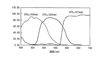
一般に、透過型のカラー液晶表示装置では、例えば、図14に示すような分光特性(スペクトル特性)の青色フィルタCFB0(450nm)、緑色フィルタCFG0(525nm)、赤色フィルタCFR0(615nm)からなる3原色フィルタを用いたカラーフィルタが、カラー液晶表示パネルの画素毎に備えられている。 In general, in a transmissive color liquid crystal display device, for example, from a blue filter CFB 0 (450 nm), a green filter CFG 0 (525 nm), and a red filter CFR 0 (615 nm) having spectral characteristics (spectral characteristics) as shown in FIG. A color filter using the three primary color filters is provided for each pixel of the color liquid crystal display panel.
これに対し、カラー液晶表示装置のバックライト装置の光源として用いられる3波長域型のCCFLが発光する白色光は、図15に示すようなスペクトルを示し、さまざまな波長帯域で異なる強度の光を含んでいることになる。 On the other hand, the white light emitted from the three-wavelength type CCFL used as the light source of the backlight device of the color liquid crystal display device shows a spectrum as shown in FIG. 15, and emits light of different intensity in various wavelength bands. Will be included.
したがって、このような3波長域発光型のCCFLを光源とするバックライト装置と、上述したようなカラーフィルタを備えるカラー液晶表示パネルとの組み合わせによって再現される色は、非常に色純度が悪いといった問題がある。 Therefore, the color reproduced by the combination of the backlight device using such a three-wavelength light emitting CCFL as the light source and the color liquid crystal display panel including the color filter as described above has very poor color purity. There's a problem.
図16,17に、上述したような3波長域型のCCFLを光源としたバックライト装置を備えるカラー液晶表示装置の色再現範囲を示す。図16,17は、それぞれ国際照明委員会(CIE)が定めたXYZ表色系のxy色度図、u’v’色度図である。 16 and 17 show the color reproduction range of a color liquid crystal display device including a backlight device using the above-described three-wavelength CCFL as a light source. 16 and 17 are xy chromaticity diagrams and u′v ′ chromaticity diagrams of the XYZ color system defined by the International Commission on Illumination (CIE), respectively.
図16,17に示すようにCCFLを光源としたバックライト装置を備えたカラー液晶表示装置の色再現範囲は、カラーテレビジョンの放送方式として採用されているNTSC(National Television System Committee)方式の規格で定められている色再現範囲より狭い範囲となっており、現行のテレビジョン放送に十分対応できているとはいえないといった問題がある。 As shown in FIGS. 16 and 17, the color reproduction range of a color liquid crystal display device having a backlight device using CCFL as a light source is a standard of the NTSC (National Television System Committee) system adopted as a color television broadcasting system. There is a problem that the color reproduction range is narrower than the color reproduction range defined in the above, and it cannot be said that the current television broadcast can be sufficiently handled.
また、CCFLは、蛍光管内に水銀を封入するため、環境への悪影響が考えられるため、今後、バックライト装置の光源として、CCFLに代わる光源が求められている。そこで、CCFLに代わる光源として発光ダイオード(LED:Light Emitting Diode)が有望視されている。青色発光ダイオードの開発により、光の三原色である赤色光、緑色光、青色光をそれぞれ発光する発光ダイオードが揃ったことになる。したがって、この発光ダイオードをバックライト装置の光源とすることで、カラー液晶表示パネルを介した色光の色純度が高くなるため、色再現範囲をNTSC方式で規定される程度まで広げることが期待されている。 In addition, since CCFL encloses mercury in a fluorescent tube, there is an adverse effect on the environment. Therefore, in the future, a light source that replaces CCFL is required as a light source of a backlight device. Therefore, a light emitting diode (LED) is promising as a light source to replace CCFL. With the development of blue light-emitting diodes, light-emitting diodes that emit the three primary colors of light, red light, green light, and blue light, have been prepared. Therefore, when this light emitting diode is used as the light source of the backlight device, the color purity of the color light through the color liquid crystal display panel is increased, so that the color reproduction range is expected to be expanded to the extent specified by the NTSC system. Yes.
しかしながら、発光ダイオードを光源とするバックライト装置を使用したカラー液晶表示装置の色再現範囲は、未だ、NTSC方式で規定された色再現範囲を満たすほど十分広くないといった問題がある。 However, there is still a problem that the color reproduction range of a color liquid crystal display device using a backlight device using a light emitting diode as a light source is not wide enough to satisfy the color reproduction range defined by the NTSC system.
そこで、本発明は、上述したような問題を解決するために案出されたものであり、バックライト方式の液晶表示装置の広色域化を可能にするバックライト装置及びこのバックライト装置を備えたカラー液晶表示装置を提供することを目的とする。 Accordingly, the present invention has been devised to solve the above-described problems, and includes a backlight device that enables a wide color gamut of a backlight type liquid crystal display device, and the backlight device. Another object is to provide a color liquid crystal display device.
上述の目的を達成するために、本発明に係るバックライト装置は、赤色光、緑色光、青色光を波長選択透過する3原色フィルタからなるカラーフィルタを備えた透過型のカラー液晶表示パネルを背面側から白色光で照明するバックライト装置であって、当該バックライト装置は、ピーク波長λprが、625nm≦λpr≦685nmである赤色光を発光する赤色発光ダイオード、ピーク波長λpgが、505nm≦λpg≦540nmである緑色光を発光する緑色発光ダイオード及びピーク波長λpbが、420nm≦λpb≦465nmである青色光を発光する青色発光ダイオードからなる光源と、上記光源から発光された赤色光、緑色光及び青色光を混色して、上記白色光とする混色手段とを備え、上記白色光の色温度が、10000±1000K(ケルビン)となるように、上記赤色発光ダイオード、上記緑色発光ダイオード及び上記青色発光ダイオードから発光させる上記赤色光、上記緑色光及び上記青色光の発光強度を調整して、上記赤色光のスペクトルの半値幅hwrを20nm≦hwr≦25nm、上記緑色光のスペクトルの半値幅hwgを30nm≦hwg≦40nm、上記青色光のスペクトルの半値幅hwbを25nm≦hwb≦30nmとすることを特徴とする。 In order to achieve the above-described object, a backlight device according to the present invention has a transmissive color liquid crystal display panel provided with a color filter including three primary color filters that selectively transmit red light, green light, and blue light with wavelengths. A backlight device that illuminates with white light from the side, wherein the backlight device emits red light having a peak wavelength λpr of 625 nm ≦ λpr ≦ 685 nm, a peak wavelength λpg of 505 nm ≦ λpg ≦ A green light emitting diode that emits green light having a wavelength of 540 nm and a blue light emitting diode that emits blue light having a peak wavelength λpb of 420 nm ≦ λpb ≦ 465 nm, and red light, green light, and blue light emitted from the light source. Color mixing means for mixing the light into the white light, and the color temperature of the white light is 10,000 ± 1 The spectrum of the red light is adjusted by adjusting the emission intensity of the red light, the green light and the blue light emitted from the red light emitting diode, the green light emitting diode and the blue light emitting diode so as to be 00K (Kelvin). The half-value width hwr is 20 nm ≦ hwr ≦ 25 nm, the half-value width hwg of the green light spectrum is 30 nm ≦ hwg ≦ 40 nm, and the half-value width hwb of the blue light spectrum is 25 nm ≦ hwb ≦ 30 nm.
また、上述の目的を達成するために、本発明に係るカラー液晶表示装置は、赤色光、緑色光、青色光を波長選択透過する3原色フィルタからなるカラーフィルタを備えた透過型のカラー液晶表示パネルと、上記カラー液晶表示パネルを背面側から白色光で照明するバックライト装置とを備えるカラー液晶表示装置であって、上記バックライト装置は、ピーク波長λprが、625nm≦λpr≦685nmである赤色光を発光する赤色発光ダイオード、ピーク波長λpgが、505nm≦λpg≦540nmである緑色光を発光する緑色発光ダイオード及びピーク波長λpbが、420nm≦λpb≦465nmである青色光を発光する青色発光ダイオードからなる光源と、上記光源から発光された赤色光、緑色光及び青色光を混色して、上記白色光とする混色手段とを備え、上記バックライト装置は、上記白色光の色温度が、10000±1000K(ケルビン)となるように、上記赤色発光ダイオード、上記緑色発光ダイオード及び上記青色発光ダイオードから発光させる上記赤色光、上記緑色光及び上記青色光の発光強度を調整して、上記赤色光のスペクトルの半値幅hwrを20nm≦hwr≦25nm、上記緑色光のスペクトルの半値幅hwgを30nm≦hwg≦40nm、上記青色光のスペクトルの半値幅hwbを25nm≦hwb≦30nmとすることを特徴とする。 In order to achieve the above object, a color liquid crystal display device according to the present invention is a transmissive color liquid crystal display including a color filter composed of three primary color filters that selectively transmit red light, green light, and blue light. A color liquid crystal display device comprising a panel and a backlight device that illuminates the color liquid crystal display panel with white light from the back side, wherein the backlight device has a red wavelength with a peak wavelength λpr of 625 nm ≦ λpr ≦ 685 nm From a red light emitting diode that emits light, a green light emitting diode that emits green light with a peak wavelength λpg of 505 nm ≦ λpg ≦ 540 nm, and a blue light emitting diode that emits blue light with a peak wavelength λpb of 420 nm ≦ λpb ≦ 465 nm The light source and the red light, green light and blue light emitted from the light source The backlight device emits light from the red light emitting diode, the green light emitting diode, and the blue light emitting diode so that the color temperature of the white light is 10,000 ± 1000 K (Kelvin). The emission intensity of the red light, the green light, and the blue light is adjusted so that the half-value width hwr of the spectrum of the red light is 20 nm ≦ hwr ≦ 25 nm, and the half-value width hwg of the spectrum of the green light is 30 nm ≦ hwg ≦ The full width at half maximum hwb of the blue light spectrum is 25 nm ≦ hwb ≦ 30 nm.
本発明は、バックライト装置において、ピーク波長λprが、625nm≦λpr≦685nmである赤色光を発光する赤色発光ダイオード、ピーク波長λpgが、505nm≦λpg≦540nmである緑色光を発光する緑色発光ダイオード及びピーク波長λpbが、420nm≦λpb≦465nmである青色光を発光する青色発光ダイオードからなる光源によって発光された赤色光、緑色光及び青色光を混色して白色光を生成する。そして、この白色光で、赤色光、緑色光、青色光を波長選択透過する3原色フィルタからなるカラーフィルタを備えた透過型のカラー液晶表示パネルを背面側から照明する。 The present invention relates to a red light emitting diode that emits red light having a peak wavelength λpr of 625 nm ≦ λpr ≦ 685 nm, and a green light emitting diode that emits green light having a peak wavelength λpg of 505 nm ≦ λpg ≦ 540 nm. In addition, white light is generated by mixing red light, green light, and blue light emitted by a light source including a blue light emitting diode that emits blue light whose peak wavelength λpb is 420 nm ≦ λpb ≦ 465 nm. Then, with this white light, a transmissive color liquid crystal display panel provided with a color filter composed of three primary color filters that selectively transmits red light, green light, and blue light is illuminated from the back side.
これにより、光源となる赤色発光ダイオード、緑色発光ダイオード、青色発光ダイオードで発光される赤色光、緑色光、青色光の色純度を上げ、混色された白色光を広色域化することが可能となり、NTSC(National Television System Committee)比を100%以上とするような、色再現範囲を達成することを可能とする。 This makes it possible to increase the color purity of red light, green light, and blue light emitted by the red light emitting diode, green light emitting diode, and blue light emitting diode, which are light sources, and widen the color gamut of mixed white light. It is possible to achieve a color reproduction range such that the NTSC (National Television System Committee) ratio is 100% or more.
また、赤色光のピーク波長λprの範囲、625nm≦λpr≦685nmの上限値、及び青色光のピーク波長λpbの範囲、420nm≦λpb≦465nmの下限値は、比視感度も考慮されているため、赤色発光ダイオード、青色発光ダイオードのパワー効率を最適に保つことを可能とする。 Further, the range of red light peak wavelength λpr, the upper limit value of 625 nm ≦ λpr ≦ 685 nm, and the blue light peak wavelength λpb range, the lower limit value of 420 nm ≦ λpb ≦ 465 nm also take into account the relative visibility. The power efficiency of the red light emitting diode and the blue light emitting diode can be kept optimal.
また、白色光の色温度が、10000±1000K(ケルビン)となるように、赤色発光ダイオード、緑色発光ダイオード及び青色発光ダイオードから発光させる赤色光、緑色光及び青色光の発光強度を調整して、赤色光のスペクトルの半値幅hwrを20nm≦hwr≦25nm、緑色光のスペクトルの半値幅hwgを30nm≦hwg≦40nm、青色光のスペクトルの半値幅hwbを25nm≦hwb≦30nmとする。 Further, the emission intensity of red light, green light and blue light emitted from the red light emitting diode, green light emitting diode and blue light emitting diode is adjusted so that the color temperature of the white light is 10,000 ± 1000 K (Kelvin), The half-value width hwr of the spectrum of red light is 20 nm ≦ hwr ≦ 25 nm, the half-value width hwg of the spectrum of green light is 30 nm ≦ hwg ≦ 40 nm, and the half-value width hwb of the spectrum of blue light is 25 nm ≦ hwb ≦ 30 nm.
これにより、十分な輝度を確保しながら、所望の色温度となるようにホワイトバランスを取ることを可能とする。 This makes it possible to achieve white balance so as to achieve a desired color temperature while securing sufficient luminance.
以下、本発明を実施するための最良の形態について、図面を参照して詳細に説明をする。なお、本発明は、以下の例に限定されるものではなく、本発明の要旨を逸脱しない範囲で、任意に変更可能であることはいうまでもない。 Hereinafter, the best mode for carrying out the present invention will be described in detail with reference to the drawings. In addition, this invention is not limited to the following examples, It cannot be overemphasized that it can change arbitrarily in the range which does not deviate from the summary of this invention.
本発明は、例えば、図1に示すような構成のバックライト方式のカラー液晶表示装置100に適用される。
The present invention is applied to, for example, a backlight type color liquid
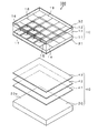
透過型のカラー液晶表示装置100は、透過型のカラー液晶表示パネル10と、このカラー液晶表示パネル10の背面側に設けられたバックライトユニット40とからなる。また、図示しないが、このカラー液晶表示装置100は、地上波や衛星波を受信するアナログチューナー、デジタルチューナーといった受信部、この受信部で受信した映像信号、音声信号をそれぞれ処理する映像信号処理部、音声信号処理部、音声信号処理部で処理された音声信号を出力するスピーカといった音声信号出力部などを備えていてもよい。
The transmissive color liquid
透過型のカラー液晶表示パネル10は、ガラス等で構成された2枚の透明な基板(TFT基板11、対向電極基板12)を互いに対向配置させ、その間隙に、例えば、ツイステッドネマチック(TN)液晶を封入した液晶層13を設けた構成となっている。TFT基板11には、マトリクス状に配置された信号線14と、走査線15と、この信号線14、走査線15の交点に配置されたスイッチング素子としての薄膜トランジスタ16と、画素電極17とが形成されている。薄膜トランジスタ16は、走査線15により、順次選択されると共に、信号線14から供給される映像信号を、対応する画素電極17に書き込む。一方、対向電極基板12の内表面には、対向電極18及びカラーフィルタ19が形成されている。
In the transmissive color liquid
続いて、カラーフィルタ19について説明をする。カラーフィルタ19は、各画素に対応した複数のセグメントに分割されている。例えば、図2に示すように、3原色である赤色フィルタCFR、緑色フィルタCFG、青色フィルタCFBの3つのセグメントに分割されている。カラーフィルタの配列パターンは、図2に示すようなストライプ配列の他に、図示しないが、デルタ配列、正方配列などがある。
Next, the
このカラー液晶表示装置100では、このような構成の透過型のカラー液晶表示パネル10を2枚の偏光板31,32で挟み、バックライトユニット40により背面側から白色光を照射した状態で、アクティブマトリクス方式で駆動することによって、所望のフルカラー映像を表示させることができる。
In this color liquid
バックライトユニット40は、上記カラー液晶表示パネル10を背面側から照明する。図1に示すように、バックライトユニット40は、光源を備え、上記光源から出射された光を混色した白色光を光出射面20aから面発光するバックライト装置20と、このバックライト装置20の光出射面20a上に順に積層させる拡散板41、輝度上昇フィルム42及び拡散板43とから構成されている。拡散板41,43は、光出射面20aから出射された白色光を、拡散させることで、面発光における輝度の均一化を行う。また輝度上昇フィルム42は、光出射面20aから出射された白色光を、光出射面20aの法線方向に立ち上げることで、面発光における輝度を上昇させる働きをする。
The
図3にバックライト装置20の概略構成図を示す。図3に示すように、バックライト装置20は、赤色光を発光する赤色発光ダイオード21R、緑色光を発光する緑色発光ダイオード21G、青色光を発光する青色発光ダイオード21Bを光源として用いている。なお、以下の説明において、赤色発光ダイオード21R、緑色発光ダイオード21G、青色発光ダイオード21Bを総称する場合は、単に発光ダイオード21と呼ぶ。
FIG. 3 shows a schematic configuration diagram of the
図3に示すように各発光ダイオード21は、基板22上に、所望の順番で一列に配列され、発光ダイオードユニット21n(nは、自然数。)を形成する。基板22上に各発光ダイオードを配列する順番は、例えば、図3に示すように、緑色発光ダイオード21Gを等間隔で配置させ、等間隔で配置させた、隣り合う緑色発光ダイオード21Gの間に、赤色発光ダイオード21R、青色発光ダイオード21Bを交互に配置されるような順番である。
As shown in FIG. 3, the
発光ダイオードユニット21nは、バックライトユニット40が照明するカラー液晶表示パネル10のサイズに応じて、バックライト装置20の筐体であるバックライトハウス23内に、複数列、配置されることになる。
The light emitting diode units 21n are arranged in a plurality of rows in the
バックライトハウス23内への発光ダイオードユニット21nの配置の仕方は、図3に示すように、発光ダイオードユニット21nの長手方向が、水平方向となるように配置してもよいし、図示しないが、発光ダイオードユニット21nの長手方向が垂直方向となるように配置してもよいし、両者を組み合わせても良い。
As shown in FIG. 3, the light emitting diode unit 21n may be arranged in the
なお、発光ダイオードユニット21nの長手方向を、水平方向或いは垂直方向とするように配置する手法は、従来までのバックライト装置の光源として利用していたCCFLの配置の仕方と同じになるため、蓄積された設計ノウハウを利用することができ、コストの削減や、製造までに要する時間を短縮することができる。 The method of arranging the light emitting diode unit 21n so that the longitudinal direction is the horizontal direction or the vertical direction is the same as the CCFL arrangement method used as the light source of the conventional backlight device. The designed design know-how can be used, and the cost and time required for manufacturing can be shortened.
バックライトハウス23内に組み込まれた赤色発光ダイオード21R、緑色発光ダイオード21G、青色発光ダイオード21Bから発光された光は、当該バックライトハウス23内で混色されて白色光とされる。このとき、各発光ダイオード21から出射した赤色光、緑色光、青色光が、バックライトハウス23内にて一様に混色されるように、各発光ダイオード21には、レンズやプリズム、反射鏡などを配置させて、広指向性の出射光が得られるようにする。
Light emitted from the red
バックライト装置20から混色されて出射された白色光は、上述した拡散板41、輝度上昇フィルム42、拡散板43を介して、カラー液晶表示パネル43に背面側から照明することになる。
The white light mixed and emitted from the
このカラー液晶表示装置100は、例えば、図4に示すような駆動回路200により駆動される。
The color liquid
この駆動回路200は、カラー液晶表示パネル10や、バックライト装置20の駆動電源を供給する電源部110、カラー液晶表示パネル10を駆動するXドライバ回路120及びYドライバ回路130、外部から供給される映像信号や、当該カラー液晶表示装置100が備える図示しない受信部で受信され、映像信号処理部で処理された映像信号が、入力端子140を介して供給されるRGBプロセス処理部150、このRGBプロセス処理部150に接続された映像メモリ160及び制御部170、バックライトユニット40のバックライト装置20を駆動制御するバックライト駆動制御部180などを備えている。
The driving
この駆動回路200において、入力端子140を介して入力された映像信号は、RGBプロセス処理部150により、クロマ処理などの信号処理がなされ、さらに、コンポジット信号からカラー液晶表示パネル10の駆動に適したRGBセパレート信号に変換されて、制御部170に供給されるとともに、画像メモリ160を介してXドライバ120に供給される。
In the
また、制御部170は、上記RGBセパレート信号に応じた所定のタイミングで、Xドライバ回路120及びYドライバ回路130を制御して、上記画像メモリ160を介してXドライバ回路120に供給されるRGBセパレート信号で、カラー液晶表示パネル10を駆動することにより、上記RGBセパレート信号に応じた映像を表示する。
Further, the
バックライト駆動制御部180は、電源110から供給される電圧から、パルス幅変調(PWM)信号を生成し、バックライト装置20の光源である各発光ダイオード21を駆動する。一般に発光ダイオードの色温度は、動作電流に依存するという特性がある。したがって、所望の輝度を得ながら、忠実に色再現させる(色温度を一定とする)には、パルス幅変調信号を使って発光ダイオード21を駆動し、色の変化を抑える必要がある。
The backlight
ユーザインターフェース300は、上述した図示しない受信部で受信するチャンネルを選択したり、同じく図示しない音声出力部で出力させる音声出力量を調整したり、カラー液晶表示パネル10を照明するバックライト装置20からの白色光の輝度調節、ホワイトバランス調節などを実行するためのインターフェースである。
The
例えば、ユーザインターフェース300から、ユーザが輝度調節をした場合には、駆動回路200の制御部170を介してバックライト駆動制御部180に輝度制御信号が伝わる。バックライト駆動制御部180は、この輝度制御信号に応じて、パルス幅変調信号のデューティ比を、赤色発光ダイオード21R、緑色発光ダイオード21G、青色発光ダイオード21B毎に変えて、赤色発光ダイオード21R、緑色発光ダイオード21G、青色発光ダイオード21Bを駆動制御することになる。
For example, when the user adjusts the brightness from the
本発明の実施例として示すカラー液晶表示装置100では、バックライト装置20から出射される白色光のホワイトバランスを、色温度が10000±1000K(ケルビン)となるように合わせることにする。このように、バックライト装置20から出射される白色光の色温度が、10000±1000Kとなるためには、赤色発光ダイオード21R、緑色発光ダイオード21G、青色発光ダイオード21Bで発光される赤色光、緑色光、青色光のピーク波長の強度比を、単純に1:1:1とするのではなく、所定の割合に変更する必要がある。
In the color liquid
図5に、赤色光、緑色光、青色光のピーク波長が、それぞれ640nm、525nm、450nmである場合の、白色光の色温度を9000K、10000K、11000Kとするような各波長光のスペクトルを示した。図5から、赤色光、緑色光、青色光のピーク強度比は、およそ0.9:0.6:1となることが分かる。 FIG. 5 shows the spectrum of each wavelength light in which the color temperature of white light is 9000K, 10000K, and 11000K when the peak wavelengths of red light, green light, and blue light are 640 nm, 525 nm, and 450 nm, respectively. It was. FIG. 5 shows that the peak intensity ratio of red light, green light, and blue light is approximately 0.9: 0.6: 1.
また、図6では、図5に示す結果を色温度毎(9000K、10000K、11000K)に、各波長光の半値幅で特定している。つまり、バックライト装置20の各発光ダイオードで発光される赤色光、緑色光、青色光のピーク強度比を0.9:0.6:1とした場合に、白色光の色温度は、10000±1000Kとなり、そのときの各波長光の半値幅は、21nm(赤色光)、34nm(緑色光)、27nm(青色光)であるといえる。
In FIG. 6, the result shown in FIG. 5 is specified for each color temperature (9000K, 10000K, 11000K) by the half-value width of each wavelength light. That is, when the peak intensity ratio of red light, green light, and blue light emitted from each light emitting diode of the
したがって、バックライト装置20が備える赤色発光ダイオード21R、緑色発光ダイオード21G、青色発光ダイオード21Bは、それぞれの半値幅が、21nm(赤色光)、34nm(緑色光)、27nm(青色光)となるようにパワーが調節されることで、白色光の色温度を上述した10000±1000Kに保つことができる。
Therefore, the red
実際には、赤色発光ダイオード21R、緑色発光ダイオード21G、青色発光ダイオード21Bから出射される赤色光、緑色光、青色光、それぞれのスペクトルの半値幅は、例えば、製造ロットの違いなど、デバイスによって若干のばらつきがあるため、上述した値を含む20nm≦hwr≦25nm(赤色光)、30nm≦hwg≦40nm(緑色光)、25nm≦hwg≦30nm(青色光)といった範囲とする。この範囲内であれば、白色光の色温度を、上述した10000±1000Kに保つことができる。バックライト装置20から出射される白色光の輝度を増したい場合には、この範囲内において、半値幅の広い各発光ダイオード21を選択して用いればよい。
Actually, the half-value widths of the red light, the green light, and the blue light emitted from the red
また、赤色光、緑色光、青色光の半値幅を広げるには、後述する各発光ダイオード21のピーク波長範囲内において、それぞれ異なるピーク波長の発光ダイオード21を意図的に選択して用いることで実現する場合もある。例えば、緑色発光ダイオード21Gを例に用いて説明すると、後述する緑色発光ダイオード21Gのピーク波長範囲内において、ピーク波長λpgが異なる複数の緑色発光ダイオード21Gを意図的に選択して光源として用い、それぞれで発光される緑色光を混色することで、全体としての緑色光の半値幅をトータルで広げることができる。他の、赤色光、青色光においても同様に、それぞれ異なるピーク波長の複数の赤色発光ダイオード21R、それぞれ異なるピーク波長の複数の青色発光ダイオード21Bを意図的に選択して光源として用いることで、半値幅をトータルで広げることができる。
Further, the half-value width of red light, green light, and blue light can be increased by intentionally selecting and using
緑色発光第オート21Gは、特に後述する比視感度の関係から半値幅を広げることが要求されるため、緑色発光ダイオード21Gで発光される緑色光のスペクトルの半値幅として、とりうる範囲を上述したように、30nm≦hwg≦40nm(緑色光)とし、赤色光、青色光と比較して5nm程度広くしている。
Since the green
このような構成のカラー液晶表示装置100では、カラー液晶表示パネル10が備えるカラーフィルタ19は、例えば、それぞれ図7に示すような分光特性となる赤色フィルタCFR(635nm)、緑色フィルタCFG(520nm)、青色フィルタCFB(455nm)によって構成されている。なおカッコ内の数値は、各フィルタのピーク透過波長を示している。このカラーフィルタ19の赤色フィルタCFR(635nm)の透過波長帯域は、従来の技術として、図14に示す赤色フィルタCFR0(615nm)より、20nm程度、長波長側にシフトさせており、色純度を上げ、色域を広げるために、緑色発光ダイオード21Gで発光される緑色光の波長帯域が当該赤色フィルタCFRの透過波長帯域に、なるべくかからないようにしている。
In the color liquid
また、赤色発光ダイオード21Rで発光される赤色光の波長帯域は、このシフトされた赤色フィルタCFRの透過波長帯域によってほぼ決まるため、赤色フィルタCFRの透過波長帯域を長波長側にシフトさせたことで、赤色光の波長帯域が緑色フィルタCFGの透過波長帯域にかかることも防ぐことができる。
Further, since the wavelength band of the red light emitted from the red
図示しないが、カラーフィルタ19の青色フィルタCFBを短波長側にシフトした場合も、同じ効果が得られ、色純度を上げ、色域を広げることができる。
Although not shown, when the blue filter CFB of the
このようなカラーフィルタ19を備えるカラー液晶表示パネル10をバックライト装置20で照明する場合、光源となる赤色発光ダイオード21R、緑色発光ダイオード21G、青色発光ダイオード21Bの波長帯域を適切に選択しないと、従来技術で説明したCCFLのように色純度が悪化し、色域を狭めることになってしまう。理想的には、緑色発光ダイオード21Gで発光される緑色光のピーク波長を中心にして、赤色発光ダイオード21Rで発光される赤色光のピーク波長をなるべく長波長側とし、緑色フィルタCFGを透過しないようにし、青色発光ダイオード21Bで発光される青色光のピーク波長をなるべく短波長側とし、緑色フィルタCFGを透過しないようにする。
When illuminating the color liquid
しかしながら、人の目の光に対する感度(視感度)は、波長によって異なっており、図8に示すように、555nmでピークをとり、長波長側、短波長側になるにつれ低くなっていく。図8は、視感度がピークとなる555nmを1とした比視感度曲線である。 However, the sensitivity of human eyes to light (visibility) varies depending on the wavelength, and as shown in FIG. 8, it takes a peak at 555 nm and becomes lower as the wavelength becomes longer and shorter. FIG. 8 is a relative visibility curve with 555 nm being 1 at which the visibility reaches a peak.
したがって、赤色発光ダイオード21Rで発光される赤色光のピーク波長、青色発光ダイオード21Bで発光される青色光のピーク波長をそれぞれ、長波長側、短波長側にシフトしすぎると視感度が下がるため、視感度をあげるためには非常に高いパワーが必要になってしまう。
Accordingly, if the peak wavelength of the red light emitted from the red
そこで、赤色発光ダイオード21Rで発光される赤色光のピーク波長、青色発光ダイオード21Bで発光される青色光のピーク波長を、パワー効率を下げない程度に、それぞれ長波長側、短波長側にシフトさせることで、色純度を上げ、色域を広げることが可能となる。
Therefore, the peak wavelength of the red light emitted from the red
以下に、バックライト装置20の光源である赤色発光ダイオード21R、緑色発光ダイオード21G、青色発光ダイオード21Bのピーク波長をそれぞれシフトさせ(波長帯域を変え)、上述したパワー効率の低減を避けながら、色純度が高く、色域が広い白色光となるような最適なピーク波長帯域を決定する。
In the following, the peak wavelengths of the red
具体的には、2つの発光ダイオードのピーク波長を固定しておき、残る一つの発光ダイオードをピーク波長の異なるものを幾つか用意して、それらを取り替えながらそのときのNTSC(National Television System Committee)比を取り、NTSC比が100%を越えた場合の波長帯域を、赤色発光ダイオード21R、緑色発光ダイオード21G、青色発光ダイオード21Bで発光させる最適なピーク波長帯域とする。このとき、赤色光のピーク波長、青色光のピーク波長は、上述した視感度によって決まるパワー効率を低下させない範囲内とする。
Specifically, the peak wavelengths of the two light emitting diodes are fixed, and several remaining light emitting diodes having different peak wavelengths are prepared, and the NTSC (National Television System Committee) at that time is replaced while replacing them. The wavelength band when the NTSC ratio exceeds 100% is set to the optimum peak wavelength band in which the red
{赤色発光ダイオード21R}
まず、青色発光ダイオード21B、緑色発光ダイオード21Gのピーク波長を固定し、異なるピーク波長の赤色発光ダイオード21Rを用いて、NTSC比を測定し、赤色発光ダイオード21Rの最適なピーク波長帯域を求める。
{Red
First, the peak wavelengths of the blue
図9(a)は、図7でも示したカラーフィルタ19の分光特性と、赤色発光ダイオード21R、緑色発光ダイオード21G、青色発光ダイオード21Bで発光された赤色光、緑色光、青色光の波長スペクトルを示した図である。赤色発光ダイオード21Rは、ピーク波長が(600+10N)nmの赤色発光ダイオード21RN(N=0,1,2,…7,8,9)を10個用意した。
FIG. 9A shows the spectral characteristics of the
図9(b)は、ピーク波長が(600+10N)nmの赤色発光ダイオード21RNを用いた際のNTSC比を測定した結果である。図9(b)に示すように、赤色発光ダイオード21RNのピーク波長λprが625nm≦λpr≦685nm以下のときNTSC比が100%以上となる。
9 (b) is a result of measuring the NTSC ratio when the peak wavelength was used (600 + 10N) nm of red
したがって、赤色発光ダイオード21Rの最適なピーク波長帯域は、625nm≦λpr≦685nmということになる。
Therefore, the optimum peak wavelength band of the red
{緑色発光ダイオード21G}
次に、赤色発光ダイオード21R、青色発光ダイオード21Bのピーク波長を固定して、異なるピーク波長の緑色発光ダイオード21Gを用いて、NTSC比を測定し、緑色発光ダイオード21Gの最適なピーク波長帯域を求める。
{Green light-emitting
Next, the peak wavelengths of the red
図10(a)は、図7でも示したカラーフィルタ19の分光特性と、赤色発ダイオード21R、緑色発光ダイオード21G、青色発光ダイオード21Bで発光された赤色光、緑色光、青色光の波長スペクトルを示した図である。緑色発光ダイオード21Gは、ピーク波長が(495+10N)nmの緑色発光ダイオード21GN(N=0,1,2,3,4,5,6)を7個用意した。
FIG. 10A shows the spectral characteristics of the
図10(b)は、ピーク波長が(495+10N)nmの緑色発光ダイオード21GNを用いた際のNTSC比を測定した結果である。図10(b)に示すように緑色発光ダイオード21GNのピーク波長λpgが505nm≦λpg≦540nm以下のとき、NTSC比が100%以上となる。
Figure 10 (b) is a result of measuring the NTSC ratio when the peak wavelength was used (495 + 10N) nm of green
したがって、緑色発光ダイオード21Gの最適なピーク波長帯域は、505nm≦λpg≦540nmということになる。
Therefore, the optimum peak wavelength band of the green
{青色発光ダイオード21B}
続いて、赤色発光ダイオード21R、緑色発光ダイオード21Gのピーク波長を固定して、異なるピーク波長の青色発光ダイオード21Bを用いて、NTSC比を測定し、青色発光ダイオード21Bの最適なピーク波長帯域を求める。
{Blue
Subsequently, the peak wavelength of the red
図11(a)は、図7でも示したカラーフィルタ19の分光特性と、赤色発ダイオード21R、緑色発光ダイオード21G、青色発光ダイオード21Bで発光された赤色光、緑色光、青色光の波長スペクトルを示した図である。青色発光ダイオード21Bは、ピーク波長が(410+10N)nmの青色発光ダイオード21BN(N=0,1,2,…5,6,7)を8個用意した。
FIG. 11A shows the spectral characteristics of the
図11(b)は、ピーク波長が(410+10N)nmの青色発光ダイオード21BNを用いた際のNTSC比を測定した結果である。図11(b)に示すように青色発光ダイオード21BNのピーク波長λpbが420nm≦λpb≦465nmのとき、NTSC比が100%以上となる。
Figure 11 (b) is a result of measuring the NTSC ratio when the peak wavelength was used (410 + 10N) nm of the blue
したがって、青色発光ダイオード21Bの最適なピーク波長帯域は、420nm≦λpr≦465nmということになる。
Therefore, the optimum peak wavelength band of the blue
このように、赤色発光ダイオード21R、緑色発光ダイオード21G、青色発光ダイオード21Bから発光される赤色光、緑色光、青色光のピーク波長をそれぞれ上述した範囲内とすることで、バックライト装置20から出射される白色光の色純度を高め、従来の技術として示したCCFLを光源として用いた場合に較べて色域を拡げることができる。したがって、カラー液晶表示装置100の色再現範囲を非常に広くすることができる。
Thus, the red light emitted from the red
ここで、アメリカの画家マンセル(A.H.Munsell 1858〜1918)が考案した色の表示体系であるマンセル表色系に従う、マンセル・カラーカスケードと呼ばれる768色のカラーチャートを用いて、赤色発光ダイオード21R、緑色発光ダイオード21G、青色発光ダイオード21Bで発光される赤色光、緑色光、青色光が、上述したピーク波長範囲内である場合の色再現範囲を検証する。
Here, using a color chart of 768 colors called Munsell color cascade according to the Munsell color system which is a color display system devised by American painter Munsell (AHMunsell 1858-1918), red
マンセル・カラーカスケードは、16階調48色相(16×48=768)を、最も彩度が高い色材の色を色票として作成したカラーチャートである。マンセル・カラーカスケードは、色素を色の3属性、すなわち色相・明度・彩度に従って、それぞれ、3次元座標軸内の一点に対応するように配列した表示体系である。 The Munsell color cascade is a color chart in which 16 gradations and 48 hues (16 × 48 = 768) are created using the color of the color material with the highest saturation as the color chart. The Munsell color cascade is a display system in which pigments are arranged to correspond to one point in a three-dimensional coordinate axis according to three attributes of color, that is, hue, brightness, and saturation.
図12,13は、それぞれ国際照明委員会(CIE)が定めたXYZ表色系のxy色度図、u’v’色度図であり、それぞれ、上述した各発光ダイオード21を光源とするバックライト装置20を備えるカラー液晶表示装置100の色再現範囲を示すと共に、上述したカラーチャートを“□”として色度図中にプロットしている。図12,13に示すカラー液晶表示装置100の色再現範囲は、上述した各発光ダイオードのピーク波長範囲、具体的には、赤色発光ダイオード21Rでは、625nm≦λpr≦685nm以下、緑色発光ダイオード21Gでは、505nm≦λpg≦540nm、青色発光ダイオード21Bでは、420nm≦λpb≦465nmの範囲から、色再現範囲が最も狭くなる場合を色度図内に三角形として示している。
FIGS. 12 and 13 are xy chromaticity diagrams and u′v ′ chromaticity diagrams of the XYZ color system defined by the International Commission on Illumination (CIE), respectively. The color reproduction range of the color liquid
マンセル・カラーカスケードは、実際に存在する物体の色域の色立体(物体の色を表す三つの要素(色相・彩度・明度)を三次元空間の座標と見なし、色をその空間内の点として表したもの)の外殻をかたどったカラーチャートであると考えることができる。したがって、このカラーチャートの値がどれだけ含まれているか検証することは、カラー液晶表示装置100といったカラーディスプレイの色再現範囲を評価する上で非常に重要となる。
Munsell Color Cascade is a color solid in the color gamut of an object that actually exists (three elements representing the color of the object (hue, saturation, brightness) are considered as coordinates in a three-dimensional space, and the color is a point in that space. It can be thought of as a color chart in the shape of the outer shell. Therefore, it is very important to verify how many values of the color chart are included in evaluating the color reproduction range of a color display such as the color liquid
図12,13に示すように、上述したNTSC100%以上を達成する、各発光ダイオード21のピーク波長範囲は、このピーク波長範囲において色再現範囲が最も狭くなる場合であっても、マンセル・カラーカスケードとして定義されるカラーチャートをほぼ含むことができるため、カラー液晶表示装置100は、視覚的にも優れた鮮やかな色を再現することができる。
As shown in FIGS. 12 and 13, the peak wavelength range of each light-emitting
10 カラー液晶表示パネル、19 カラーフィルタ、20 バックライト装置、21R 赤色発光ダイオード、21G 緑色発光ダイオード、21B 青色発光ダイオード、40 バックライトユニット、41,43 拡散板、42 輝度上昇フィルム 10 color liquid crystal display panel, 19 color filter, 20 backlight device, 21R red light emitting diode, 21G green light emitting diode, 21B blue light emitting diode, 40 backlight unit, 41, 43 diffuser plate, 42 brightness enhancement film
Claims (8)
当該バックライト装置は、ピーク波長λprが、625nm≦λpr≦685nmである赤色光を発光する赤色発光ダイオード、ピーク波長λpgが、505nm≦λpg≦540nmである緑色光を発光する緑色発光ダイオード及びピーク波長λpbが、420nm≦λpb≦465nmである青色光を発光する青色発光ダイオードからなる光源と、上記光源から発光された赤色光、緑色光及び青色光を混色して、上記白色光とする混色手段とを備え、
上記白色光の色温度が、10000±1000K(ケルビン)となるように、上記赤色発光ダイオード、上記緑色発光ダイオード及び上記青色発光ダイオードから発光させる上記赤色光、上記緑色光及び上記青色光の発光強度を調整して、上記赤色光のスペクトルの半値幅hwrを20nm≦hwr≦25nm、上記緑色光のスペクトルの半値幅hwgを30nm≦hwg≦40nm、上記青色光のスペクトルの半値幅hwbを25nm≦hwb≦30nmとすること
を特徴とするバックライト装置。 A backlight device for illuminating a transmissive color liquid crystal display panel having a color filter composed of three primary color filters that selectively transmit red light, green light, and blue light with white light from the back side,
The backlight device includes a red light emitting diode that emits red light having a peak wavelength λpr of 625 nm ≦ λpr ≦ 685 nm, a green light emitting diode that emits green light having a peak wavelength λpg of 505 nm ≦ λpg ≦ 540 nm, and a peak wavelength. a light source composed of a blue light emitting diode that emits blue light with λpb of 420 nm ≦ λpb ≦ 465 nm, and a color mixing unit that mixes red light, green light, and blue light emitted from the light source to produce the white light. With
Emission intensity of the red light, the green light, and the blue light emitted from the red light emitting diode, the green light emitting diode, and the blue light emitting diode so that the color temperature of the white light is 10,000 ± 1000 K (Kelvin). The half-value width hwr of the red light spectrum is 20 nm ≦ hwr ≦ 25 nm, the half-value width hwg of the green light spectrum is 30 nm ≦ hwg ≦ 40 nm, and the half-value width hwb of the blue light spectrum is 25 nm ≦ hwb A backlight device characterized in that ≦ 30 nm.
を特徴とする請求項1記載のバックライト装置。 2. The backlight device according to claim 1, wherein a plurality of red light emitting diodes having a peak wavelength λpr satisfying 625 nm ≦ λpr ≦ 685 nm and having different peak wavelengths λpr are used as the red light emitting diode used for the light source. .
を特徴とする請求項1記載のバックライト装置。 2. The backlight device according to claim 1, wherein a plurality of green light emitting diodes having a peak wavelength λpg satisfying 505 nm ≦ λpg ≦ 540 nm and different peak wavelengths λpg are used as the green light emitting diode used for the light source. .
を特徴とする請求項1記載のバックライト装置。 2. The backlight device according to claim 1, wherein a plurality of blue light emitting diodes having peak wavelengths λpb satisfying 420 nm ≦ λpb ≦ 465 nm and different peak wavelengths λpb are used as the blue light emitting diodes used for the light source. .
上記バックライト装置は、ピーク波長λprが、625nm≦λpr≦685nmである赤色光を発光する赤色発光ダイオード、ピーク波長λpgが、505nm≦λpg≦540nmである緑色光を発光する緑色発光ダイオード及びピーク波長λpbが、420nm≦λpb≦465nmである青色光を発光する青色発光ダイオードからなる光源と、上記光源から発光された赤色光、緑色光及び青色光を混色して、上記白色光とする混色手段とを備え、
上記バックライト装置は、上記白色光の色温度が、10000±1000K(ケルビン)となるように、上記赤色発光ダイオード、上記緑色発光ダイオード及び上記青色発光ダイオードから発光させる上記赤色光、上記緑色光及び上記青色光の発光強度を調整して、上記赤色光のスペクトルの半値幅hwrを20nm≦hwr≦25nm、上記緑色光のスペクトルの半値幅hwgを30nm≦hwg≦40nm、上記青色光のスペクトルの半値幅hwbを25nm≦hwb≦30nmとすること
を特徴とするカラー液晶表示装置。 A transmissive color liquid crystal display panel including a color filter including three primary color filters that selectively transmits red light, green light, and blue light; and a backlight device that illuminates the color liquid crystal display panel with white light from the back side; A color liquid crystal display device comprising:
The backlight device includes a red light emitting diode that emits red light having a peak wavelength λpr of 625 nm ≦ λpr ≦ 685 nm, a green light emitting diode that emits green light having a peak wavelength λpg of 505 nm ≦ λpg ≦ 540 nm, and a peak wavelength. a light source composed of a blue light emitting diode that emits blue light with λpb of 420 nm ≦ λpb ≦ 465 nm, and a color mixing unit that mixes red light, green light, and blue light emitted from the light source to produce the white light. With
The backlight device includes the red light, the green light, and the red light emitted from the red light emitting diode, the green light emitting diode, and the blue light emitting diode so that the color temperature of the white light is 10,000 ± 1000 K (Kelvin). By adjusting the emission intensity of the blue light, the half-value width hwr of the red light spectrum is 20 nm ≦ hwr ≦ 25 nm, the half-value width hwg of the green light spectrum is 30 nm ≦ hwg ≦ 40 nm, and the half-value width of the blue light spectrum is half A color liquid crystal display device, wherein the value width hwb is 25 nm ≦ hwb ≦ 30 nm.
を特徴とする請求項5記載のカラー液晶表示装置。 6. The color liquid crystal display according to claim 5, wherein a plurality of red light emitting diodes having a peak wavelength λpr satisfying 625 nm ≦ λpr ≦ 685 nm and having different peak wavelengths λpr are used as the red light emitting diode used in the light source. apparatus.
を特徴とする請求項5記載のカラー液晶表示装置。 6. The color liquid crystal display according to claim 5, wherein a plurality of green light emitting diodes having a peak wavelength λpg satisfying 505 nm ≦ λpg ≦ 540 nm and different peak wavelengths λpg are used as the green light emitting diode used for the light source. apparatus.
を特徴とする請求項5記載のカラー液晶表示装置。 6. The color liquid crystal display according to claim 5, wherein a plurality of blue light emitting diodes having a peak wavelength λpb satisfying 420 nm ≦ λpb ≦ 465 nm and different peak wavelengths λpb are used as the blue light emitting diode used for the light source. apparatus.
Priority Applications (7)
| Application Number | Priority Date | Filing Date | Title |
|---|---|---|---|
| JP2004141568A JP2005321727A (en) | 2004-05-11 | 2004-05-11 | Backlight device and color liquid crystal display |
| US11/596,098 US7789527B2 (en) | 2004-05-11 | 2005-04-28 | Backlight device and color liquid crystal display |
| CN2005800152412A CN1954250B (en) | 2004-05-11 | 2005-04-28 | Backlight device and color liquid crystal display unit |
| KR1020067022607A KR20070006878A (en) | 2004-05-11 | 2005-04-28 | Backlight device and color liquid crystal display unit |
| EP05737371A EP1752703A4 (en) | 2004-05-11 | 2005-04-28 | Backlight device and color liquid crystal display unit |
| PCT/JP2005/008180 WO2005109087A1 (en) | 2004-05-11 | 2005-04-28 | Backlight device and color liquid crystal display unit |
| TW094113934A TW200540522A (en) | 2004-05-11 | 2005-04-29 | Backlight device and color liquid crystal display unit |
Applications Claiming Priority (1)
| Application Number | Priority Date | Filing Date | Title |
|---|---|---|---|
| JP2004141568A JP2005321727A (en) | 2004-05-11 | 2004-05-11 | Backlight device and color liquid crystal display |
Publications (1)
| Publication Number | Publication Date |
|---|---|
| JP2005321727A true JP2005321727A (en) | 2005-11-17 |
Family
ID=35320355
Family Applications (1)
| Application Number | Title | Priority Date | Filing Date |
|---|---|---|---|
| JP2004141568A Pending JP2005321727A (en) | 2004-05-11 | 2004-05-11 | Backlight device and color liquid crystal display |
Country Status (7)
| Country | Link |
|---|---|
| US (1) | US7789527B2 (en) |
| EP (1) | EP1752703A4 (en) |
| JP (1) | JP2005321727A (en) |
| KR (1) | KR20070006878A (en) |
| CN (1) | CN1954250B (en) |
| TW (1) | TW200540522A (en) |
| WO (1) | WO2005109087A1 (en) |
Cited By (5)
| Publication number | Priority date | Publication date | Assignee | Title |
|---|---|---|---|---|
| JP2010145732A (en) * | 2008-12-18 | 2010-07-01 | Toppan Printing Co Ltd | Liquid crystal image display device |
| JP2012182152A (en) * | 2006-03-21 | 2012-09-20 | Semiconductor Energy Lab Co Ltd | Lighting device and display device |
| CN103487991A (en) * | 2013-06-28 | 2014-01-01 | 友达光电股份有限公司 | Display device |
| WO2015182272A1 (en) * | 2014-05-30 | 2015-12-03 | シャープ株式会社 | Light emitting device |
| KR20170072222A (en) * | 2014-10-30 | 2017-06-26 | 도요보 가부시키가이샤 | Liquid crystal display device and polarizing plate |
Families Citing this family (22)
| Publication number | Priority date | Publication date | Assignee | Title |
|---|---|---|---|---|
| KR20070039539A (en) * | 2004-07-15 | 2007-04-12 | 소니 가부시끼 가이샤 | Color filter and color liquid crystal display device |
| JP4815781B2 (en) * | 2004-10-20 | 2011-11-16 | ソニー株式会社 | Color liquid crystal display device and backlight device |
| JP2008076899A (en) * | 2006-09-22 | 2008-04-03 | Sony Corp | Backlight device and display device |
| JP4285532B2 (en) * | 2006-12-01 | 2009-06-24 | ソニー株式会社 | Backlight control device, backlight control method, and liquid crystal display device |
| KR100930171B1 (en) * | 2006-12-05 | 2009-12-07 | 삼성전기주식회사 | White light emitting device and white light source module using same |
| JP4264560B2 (en) * | 2007-01-24 | 2009-05-20 | ソニー株式会社 | Backlight device, backlight control method, and liquid crystal display device |
| KR20090047205A (en) * | 2007-11-07 | 2009-05-12 | 삼성에스디아이 주식회사 | Liquid crystal display device |
| US8129735B2 (en) * | 2008-09-24 | 2012-03-06 | Koninklijke Philips Electronics N.V. | LED with controlled angular non-uniformity |
| JP4888853B2 (en) | 2009-11-12 | 2012-02-29 | 学校法人慶應義塾 | Method for improving visibility of liquid crystal display device, and liquid crystal display device using the same |
| TWI398700B (en) | 2009-12-30 | 2013-06-11 | Au Optronics Corp | Display device with quantum dot phosphor and manufacturing method thereof |
| CN107656332B (en) | 2010-06-22 | 2021-10-15 | 东洋纺株式会社 | Liquid crystal display device, polarizing plate, and polarizer protective film |
| TWI414861B (en) * | 2010-09-17 | 2013-11-11 | Au Optronics Corp | Edge-type backlight module |
| TWI425276B (en) * | 2010-09-28 | 2014-02-01 | Dynascan Technology Corp | A three-dimensional display system with a liquid crystal display and a three-dimensional display system with the display |
| TWI508332B (en) * | 2011-11-09 | 2015-11-11 | Au Optronics Corp | Luminescent light source and display panel thereof |
| WO2015065341A1 (en) * | 2013-10-29 | 2015-05-07 | Intel Corporation | Gesture based human computer interaction |
| CN104968117B (en) * | 2015-07-13 | 2017-10-13 | 佛山市顺德区美的洗涤电器制造有限公司 | A kind of dish-washing machine and its three primary colours prompting control method and device |
| WO2017065148A1 (en) * | 2015-10-16 | 2017-04-20 | 東洋紡株式会社 | Liquid crystal display device and polarizing plate |
| JP6740762B2 (en) | 2016-07-13 | 2020-08-19 | 日亜化学工業株式会社 | Light emitting device and manufacturing method thereof |
| TWI636286B (en) * | 2017-03-31 | 2018-09-21 | 友達光電股份有限公司 | Display device |
| US10056530B1 (en) * | 2017-07-31 | 2018-08-21 | Eie Materials, Inc. | Phosphor-converted white light emitting diodes having narrow-band green phosphors |
| CN109523908A (en) * | 2017-09-19 | 2019-03-26 | 群创光电股份有限公司 | Display device |
| CN108984935B (en) * | 2018-07-26 | 2022-11-18 | 福建船政交通职业学院 | Design method for wide color gamut and high light efficiency spectrum |
Family Cites Families (60)
| Publication number | Priority date | Publication date | Assignee | Title |
|---|---|---|---|---|
| JPH06227284A (en) * | 1993-02-09 | 1994-08-16 | Asahi Glass Co Ltd | Head-up display |
| JP3329070B2 (en) | 1994-05-31 | 2002-09-30 | 松下電器産業株式会社 | Projection display device |
| JP3633215B2 (en) | 1996-09-17 | 2005-03-30 | セイコーエプソン株式会社 | Transflective liquid crystal device and electronic device |
| JP3292809B2 (en) * | 1996-09-25 | 2002-06-17 | 松下電器産業株式会社 | Color liquid crystal display device |
| JPH11183891A (en) | 1997-12-22 | 1999-07-09 | Casio Comput Co Ltd | Liquid crystal display element |
| US6633301B1 (en) * | 1999-05-17 | 2003-10-14 | Displaytech, Inc. | RGB illuminator with calibration via single detector servo |
| JP2001135118A (en) | 1999-11-02 | 2001-05-18 | Toshiba Corp | Panel light source device and flat display using the same |
| WO2001043113A1 (en) * | 1999-12-09 | 2001-06-14 | Koninklijke Philips Electronics N.V. | Display systems incorporating light-emitting diode light source |
| JP2001272938A (en) | 2000-03-28 | 2001-10-05 | Sharp Corp | Color tone adjusting circuit and back light module and light emitting diode display device provided with the same circuit |
| TWI240241B (en) * | 2000-05-04 | 2005-09-21 | Koninkl Philips Electronics Nv | Assembly of a display device and an illumination system |
| TW528169U (en) * | 2000-05-04 | 2003-04-11 | Koninkl Philips Electronics Nv | Assembly of a display device and an illumination system |
| JP3847532B2 (en) * | 2000-07-05 | 2006-11-22 | 株式会社日立製作所 | Liquid crystal module and liquid crystal monitor equipped with this liquid crystal module |
| JP3822037B2 (en) * | 2000-08-04 | 2006-09-13 | 株式会社日立製作所 | Liquid crystal display |
| KR100367011B1 (en) * | 2000-08-21 | 2003-01-09 | 엘지.필립스 엘시디 주식회사 | Liquid Crystal Display |
| JP3523170B2 (en) | 2000-09-21 | 2004-04-26 | 株式会社東芝 | Display device |
| JP3538149B2 (en) * | 2001-01-30 | 2004-06-14 | Nec液晶テクノロジー株式会社 | Reflection type liquid crystal display device and manufacturing method thereof |
| JP3940596B2 (en) * | 2001-05-24 | 2007-07-04 | 松下電器産業株式会社 | Illumination light source |
| DE10137042A1 (en) * | 2001-07-31 | 2003-02-20 | Patent Treuhand Ges Fuer Elektrische Gluehlampen Mbh | Planar light source based on LED |
| JP3840940B2 (en) * | 2001-09-28 | 2006-11-01 | 株式会社日立製作所 | Image display device |
| CN2606372Y (en) | 2001-10-24 | 2004-03-10 | 精工爱普生株式会社 | Liquid crystal display device and electronic apparatus |
| JP2003131229A (en) | 2001-10-29 | 2003-05-08 | Sharp Corp | Light emitting device and display device using the same |
| JP2003207770A (en) * | 2002-01-15 | 2003-07-25 | Toppan Printing Co Ltd | Color filter for liquid crystal display and liquid crystal display using the same |
| JP3924473B2 (en) | 2002-02-08 | 2007-06-06 | シャープ株式会社 | LIGHT EMITTING DEVICE AND DISPLAY DEVICE USING THE LIGHT EMITTING DEVICE |
| JP4212332B2 (en) | 2002-03-05 | 2009-01-21 | シャープ株式会社 | Display device |
| JP3766042B2 (en) | 2002-06-21 | 2006-04-12 | 三菱電機株式会社 | Rear light source for display device and liquid crystal display device |
| KR100878206B1 (en) * | 2002-08-13 | 2009-01-13 | 삼성전자주식회사 | Optical sheet and back light assembly using the same and liquid crystal display device using the same |
| JP4611604B2 (en) * | 2002-09-30 | 2011-01-12 | 独立行政法人情報通信研究機構 | Image display device |
| KR100698046B1 (en) * | 2002-12-24 | 2007-03-23 | 엘지.필립스 엘시디 주식회사 | Backlight Unit Assembly |
| JP2004212503A (en) | 2002-12-27 | 2004-07-29 | Casio Comput Co Ltd | Lighting device and its light emitting driving method, and display device |
| JP2004246117A (en) | 2003-02-14 | 2004-09-02 | Matsushita Electric Ind Co Ltd | Backlight device |
| DE602004005768T2 (en) * | 2003-03-28 | 2008-05-15 | Philips Lumileds Lighting Company LLC, (n. d. Ges. d. Staates Delaware), San Jose | Tail light illumination system and display device |
| KR100852579B1 (en) * | 2003-03-31 | 2008-08-14 | 샤프 가부시키가이샤 | Surface illumination device and liquid display device using the same |
| JP2004309509A (en) * | 2003-04-01 | 2004-11-04 | Hunet Inc | Method for adjusting display device |
| JP4417784B2 (en) | 2003-09-05 | 2010-02-17 | シャープ株式会社 | Light emitting device and display device |
| JP3813144B2 (en) | 2003-09-12 | 2006-08-23 | ローム株式会社 | Light emission control circuit |
| JP4202229B2 (en) * | 2003-10-15 | 2008-12-24 | 株式会社 日立ディスプレイズ | Liquid crystal display |
| JP4628770B2 (en) * | 2004-02-09 | 2011-02-09 | 株式会社日立製作所 | Image display device having illumination device and image display method |
| JP2005234134A (en) | 2004-02-18 | 2005-09-02 | Sony Corp | Backlight light source device for liquid crystal display, and color liquid crystal display |
| JP4280180B2 (en) | 2004-03-01 | 2009-06-17 | シャープ株式会社 | Backlight device |
| US7420632B2 (en) * | 2004-03-31 | 2008-09-02 | Toyo Ink Mfg. Co., Ltd. | Color filter and liquid crystal display device provided with the same |
| DE102004023186A1 (en) | 2004-05-11 | 2005-12-08 | Siemens Ag | Procedure for adjusting color co-ordinates of LED source of backlight of LCD display involves altering amplitude of current and then adjusting pulse width |
| KR101015299B1 (en) * | 2004-06-29 | 2011-02-15 | 엘지디스플레이 주식회사 | Liquid crystal display device having good image quality |
| US7675249B2 (en) | 2004-07-12 | 2010-03-09 | Sony Corporation | Apparatus and method for driving backlight unit |
| KR20070039539A (en) * | 2004-07-15 | 2007-04-12 | 소니 가부시끼 가이샤 | Color filter and color liquid crystal display device |
| JP2006058484A (en) | 2004-08-18 | 2006-03-02 | Sony Corp | Back light system |
| JP4815781B2 (en) * | 2004-10-20 | 2011-11-16 | ソニー株式会社 | Color liquid crystal display device and backlight device |
| US7324080B1 (en) * | 2004-12-03 | 2008-01-29 | Sysview Technology, Inc. | Backlighting in liquid crystal flat panel display |
| JP3883134B2 (en) * | 2005-01-25 | 2007-02-21 | 日東電工株式会社 | Liquid crystal display |
| JP4600098B2 (en) * | 2005-03-14 | 2010-12-15 | ソニー株式会社 | Color liquid crystal display |
| US20080111960A1 (en) * | 2005-12-19 | 2008-05-15 | Nitto Denko Corporation | Liquid Crystal Panel and Liquid Crystal Display Apparatus |
| JP4175426B2 (en) * | 2006-05-30 | 2008-11-05 | ソニー株式会社 | Backlight device and color image display device |
| JP4182989B2 (en) | 2006-05-30 | 2008-11-19 | ソニー株式会社 | Illumination device and liquid crystal display device |
| US7696964B2 (en) | 2006-06-09 | 2010-04-13 | Philips Lumileds Lighting Company, Llc | LED backlight for LCD with color uniformity recalibration over lifetime |
| JP2008051905A (en) | 2006-08-22 | 2008-03-06 | Sharp Corp | Liquid crystal display device and backlight driving method therefor |
| JP2008052131A (en) | 2006-08-25 | 2008-03-06 | Taiyo Yuden Co Ltd | Liquid crystal backlight driving device |
| JP2008076899A (en) * | 2006-09-22 | 2008-04-03 | Sony Corp | Backlight device and display device |
| JP5175504B2 (en) | 2006-10-10 | 2013-04-03 | 三洋電機株式会社 | Projection display device |
| JP4237220B2 (en) | 2006-11-13 | 2009-03-11 | シャープ株式会社 | Transmission type display device |
| JP4285532B2 (en) * | 2006-12-01 | 2009-06-24 | ソニー株式会社 | Backlight control device, backlight control method, and liquid crystal display device |
| JP4264560B2 (en) * | 2007-01-24 | 2009-05-20 | ソニー株式会社 | Backlight device, backlight control method, and liquid crystal display device |
-
2004
- 2004-05-11 JP JP2004141568A patent/JP2005321727A/en active Pending
-
2005
- 2005-04-28 CN CN2005800152412A patent/CN1954250B/en not_active Expired - Fee Related
- 2005-04-28 EP EP05737371A patent/EP1752703A4/en not_active Ceased
- 2005-04-28 US US11/596,098 patent/US7789527B2/en not_active Expired - Fee Related
- 2005-04-28 WO PCT/JP2005/008180 patent/WO2005109087A1/en not_active Application Discontinuation
- 2005-04-28 KR KR1020067022607A patent/KR20070006878A/en active IP Right Grant
- 2005-04-29 TW TW094113934A patent/TW200540522A/en not_active IP Right Cessation
Cited By (10)
| Publication number | Priority date | Publication date | Assignee | Title |
|---|---|---|---|---|
| JP2012182152A (en) * | 2006-03-21 | 2012-09-20 | Semiconductor Energy Lab Co Ltd | Lighting device and display device |
| US8733959B2 (en) | 2006-03-21 | 2014-05-27 | Semiconductor Energy Laboratory Co., Ltd. | Backlight device and display device |
| JP2010145732A (en) * | 2008-12-18 | 2010-07-01 | Toppan Printing Co Ltd | Liquid crystal image display device |
| CN103487991A (en) * | 2013-06-28 | 2014-01-01 | 友达光电股份有限公司 | Display device |
| CN103487991B (en) * | 2013-06-28 | 2016-09-07 | 友达光电股份有限公司 | Display device |
| WO2015182272A1 (en) * | 2014-05-30 | 2015-12-03 | シャープ株式会社 | Light emitting device |
| US9818731B2 (en) | 2014-05-30 | 2017-11-14 | Sharp Kabushiki Kaisha | Light emitting device |
| KR20170072222A (en) * | 2014-10-30 | 2017-06-26 | 도요보 가부시키가이샤 | Liquid crystal display device and polarizing plate |
| JP2020034950A (en) * | 2014-10-30 | 2020-03-05 | 東洋紡株式会社 | Liquid crystal display device and polarizing plate |
| KR102634613B1 (en) * | 2014-10-30 | 2024-02-06 | 도요보 가부시키가이샤 | Liquid crystal display device and polarizing plate |
Also Published As
| Publication number | Publication date |
|---|---|
| TW200540522A (en) | 2005-12-16 |
| CN1954250A (en) | 2007-04-25 |
| KR20070006878A (en) | 2007-01-11 |
| US7789527B2 (en) | 2010-09-07 |
| EP1752703A4 (en) | 2009-02-25 |
| CN1954250B (en) | 2010-05-12 |
| WO2005109087A1 (en) | 2005-11-17 |
| EP1752703A1 (en) | 2007-02-14 |
| US20080036943A1 (en) | 2008-02-14 |
| TWI327245B (en) | 2010-07-11 |
Similar Documents
| Publication | Publication Date | Title |
|---|---|---|
| US7789527B2 (en) | Backlight device and color liquid crystal display | |
| JP4635551B2 (en) | Color liquid crystal display device | |
| WO2006019016A1 (en) | Backlight device and color liquid crystal display device | |
| KR101237326B1 (en) | Backlight device and display device | |
| CN100442122C (en) | Back light system of panel type LCD | |
| US8040317B2 (en) | Backlight device having LEDs controlled as a function of target values and influential extent data | |
| JP4600098B2 (en) | Color liquid crystal display | |
| TWI261692B (en) | Color filter and color liquid crystal display device | |
| TWI287674B (en) | Color liquid crystal display device | |
| JP4650085B2 (en) | Backlight device and liquid crystal display device | |
| JP4666387B2 (en) | Backlight unit and image display device including the unit | |
| WO2015174144A1 (en) | Backlight device and liquid crystal display device provided with same | |
| JP2006259585A (en) | Color liquid crystal display device | |
| JP2016035806A (en) | Backlight device, and liquid crystal display device having the same | |
| JP2006330400A (en) | Transmission-type liquid crystal color display | |
| US20090051642A1 (en) | Backlight assembly, method of driving the same and display system having the same thereof | |
| JP2007141715A (en) | Led back light unit, and image display device equipped with the same |
Legal Events
| Date | Code | Title | Description |
|---|---|---|---|
| A131 | Notification of reasons for refusal |
Free format text: JAPANESE INTERMEDIATE CODE: A131 Effective date: 20070220 |
|
| A521 | Written amendment |
Free format text: JAPANESE INTERMEDIATE CODE: A523 Effective date: 20070423 |
|
| A02 | Decision of refusal |
Free format text: JAPANESE INTERMEDIATE CODE: A02 Effective date: 20070904 |