JP2005304792A - Method of holding reduced diameter of stent, stent with reduced diameter being held, and method to increase it - Google Patents
Method of holding reduced diameter of stent, stent with reduced diameter being held, and method to increase it Download PDFInfo
- Publication number
- JP2005304792A JP2005304792A JP2004126186A JP2004126186A JP2005304792A JP 2005304792 A JP2005304792 A JP 2005304792A JP 2004126186 A JP2004126186 A JP 2004126186A JP 2004126186 A JP2004126186 A JP 2004126186A JP 2005304792 A JP2005304792 A JP 2005304792A
- Authority
- JP
- Japan
- Prior art keywords
- stent
- reduced diameter
- wire
- end side
- diameter
- Prior art date
- Legal status (The legal status is an assumption and is not a legal conclusion. Google has not performed a legal analysis and makes no representation as to the accuracy of the status listed.)
- Granted
Links
Images

Abstract
Description
本発明は、例えば血管、尿管、胆管、気管などの人体の管状器官に挿入し、配置されるステントの縮径保持方法と、その縮径保持方法を用いた縮径保持されたステント及びそのステントの拡張方法に関する。 The present invention relates to a method for maintaining a reduced diameter of a stent that is inserted and disposed in a tubular organ of a human body such as a blood vessel, a ureter, a bile duct, and a trachea, a stent having a reduced diameter using the reduced diameter holding method, and a stent thereof The present invention relates to a method for expanding a stent.
近年、血管、尿管、胆管、気管などの人体の管状器官における治療のため、それらの患部にカテーテルを通してステントを挿入し配置することが行われている。例えば血管の狭窄部にカバー付きステントを配置して拡張したり、動脈瘤が形成された箇所にカバー付きステントを配置して動脈瘤の破裂を防止する治療方法が知られている。 In recent years, in order to treat human tubular organs such as blood vessels, ureters, bile ducts, and trachea, stents are inserted and placed through these catheters in affected areas. For example, a treatment method is known in which a covered stent is placed in a stenosis portion of a blood vessel to be expanded, or a covered stent is placed in a place where an aneurysm is formed to prevent rupture of the aneurysm.
カバー付きステントの挿入方法としては、血管等の管状器官内に経皮的にカテーテルを挿入し、このカテーテルを通してカバー付きステントを管状器官内に押出して留置させる方法も採用されている。また、治療箇所がそのような方法では挿入しにくいような位置にある場合や、治療箇所が複数あってカテーテルを通して挿入する方法では作業性が悪いような場合には、外科的に体を切開して管状器官の患部に直接カバー付きステントを挿入する方法が採用されている。 As a method for inserting a covered stent, a method is also employed in which a catheter is inserted percutaneously into a tubular organ such as a blood vessel, and the covered stent is pushed through the catheter into the tubular organ. Also, if the treatment site is difficult to insert by such a method, or if there are multiple treatment sites and the workability is poor with the method of inserting through a catheter, the body is surgically incised. A method of inserting a covered stent directly into an affected part of a tubular organ is employed.
このように、管状器官の患部に直接カバー付きステントを挿入する場合でも、管状器官の切り口等からカバー付きステントを挿入するために、カバー付きステントを縮径させた状態に保持する必要がある。しかしながら、カバー付きステントは、管状器官内に留置されたときに拡張して管状器官内壁に固定されるため、縮径させた状態に保持するためには、外部から拘束する必要がある。 As described above, even when the covered stent is inserted directly into the affected part of the tubular organ, the covered stent needs to be held in a reduced diameter state in order to insert the covered stent through the cut end of the tubular organ. However, since the covered stent is expanded and fixed to the inner wall of the tubular organ when it is placed in the tubular organ, it needs to be constrained from the outside in order to keep it in a reduced diameter state.
このような目的のため、特許文献1には、拡張可能なインプラントを潰された状態に一時的に拘束して展開部位へ送給する送給装置であって、拡張可能なインプラントを取り巻くように構成されて、該インプラントを、哺乳類の身体管腔を通して送給する間、潰れ状態に維持するシート材と、該シート材の複数部分を互いに連結して、該インプラントを該潰れ状態に維持する連結部材とを具備する装置が開示されている。
For this purpose,
また、特許文献2には、基部側端と末端とを備えたステントと、 折りたたまれた状態に前記ステントを保持するために解放可能に前記ステントに結合されたラインとを具備し、前記ラインは、前記ステントが前記基部側端から前記末端への方向に漸進的に拡張するように、解放されるべく配置されている、医療装置が開示されている。
外部のシースや特殊な装具を必要とせず、簡単な機構で、簡便にステントを縮径保持でき、さらに容易に拡張できる縮径保持方法を提供することを目的とする。 An object of the present invention is to provide a reduced diameter holding method capable of easily holding a stent with a reduced diameter and further easily expanding with a simple mechanism without requiring an external sheath or special equipment.
本発明の第一は、線材を用いて縮径させたステントの縮径を保持する縮径保持方法であり、
(1)二重に折り曲げた曲げ部Aを有する線材を縮径させたステントの外周に1巻きし、ステント外周に巻かれた主部の動端側線材を二重に折り曲げて、曲げ部Aの輪に通す、
(2)曲げ部の輪を通した動端側線材を二重に折り曲げて曲げ部Bを作成し、この曲げ部Bを有する二重に折り曲げた動端側線材を上記(1)の線材と同じ巻き方向に縮径させたステントの外周に1巻きし、ステント外周に巻かれた主部の動端側線材を二重に折り曲げて、曲げ部Bの輪に通す、
さらに上記(2)を1回以上繰り返すことにより縮径させたステントの縮径を保持することを特徴とするステントの縮径保持方法を提供することである。
ステントの縮径保持方法は、縮径されたステントの先端部又は先端部近傍から先端部の反対側の基端部又は基端部近傍まで、上記(1)と、上記(2)を1回以上又は複数回繰り返すことにより、縮径保持されていることが好ましい。
ステントの縮径保持方法は、先端部又は先端部近傍の保持間隔が狭いことが好ましい。
ステントの縮径保持方法は、上記(1)及び(2)において、ステント外周に巻かれた主部の動端側線材を二重に折り曲げている線材と、曲げ部Bとの交差部分が、ステントの長さ方向に対し、直線状になっていることが好ましい。
The first of the present invention is a reduced diameter holding method for holding the reduced diameter of a stent that has been reduced in diameter using a wire,
(1) A wire having a bent portion A bent twice is wound around the outer periphery of a stent having a reduced diameter, and the main moving end side wire wound around the outer periphery of the stent is bent twice to bend the bent portion A. Through the ring of
(2) The bending end B is formed by bending the moving end side wire rod that has passed through the ring of the bending portion, and the bending end portion B having the bending portion B is formed as the moving end side wire rod with the wire rod of the above (1). One turn on the outer circumference of the stent reduced in diameter in the same winding direction, and the main end of the moving end side wire wound around the outer circumference of the stent is double-folded and passed through the loop of the bent portion B.
It is another object of the present invention to provide a method for maintaining a reduced diameter of a stent, characterized by maintaining the reduced diameter of a stent that has been reduced in diameter by repeating the above (2) at least once.
The method of maintaining the reduced diameter of the stent is as follows. (1) and (2) are performed once from the distal end or the vicinity of the distal end of the reduced diameter stent to the proximal end or the vicinity of the proximal end opposite to the distal end. The diameter reduction is preferably maintained by repeating the above or a plurality of times.
In the method for maintaining the reduced diameter of the stent, it is preferable that the holding interval near the tip or near the tip is narrow.
In the method of maintaining the reduced diameter of the stent, in (1) and (2) above, the intersection of the bent portion B and the wire portion that is double-folded on the moving end side wire rod wound around the outer periphery of the stent, It is preferable that it is linear with respect to the length direction of the stent.
本発明の第二は、本発明の第一の縮径保持方法により得られる縮径保持されたステントを提供することである。
本発明の第三は、縮径保持されたステントの外周に、さらにカバーを設けた縮径保持されたステント提供することである。
The second of the present invention is to provide a stent having a reduced diameter obtained by the first method for maintaining a reduced diameter of the present invention.
A third aspect of the present invention is to provide a stent having a reduced diameter which is further provided with a cover on the outer periphery of the stent having a reduced diameter.
本発明の第四は、本発明の第二の縮径保持されたステントの拡張方法であり、
二重に折り曲げた曲げ部Aを有する線材の動端側線材の端部又は端部近傍を引くことにより縮径保持されたステントを拡張させることを特徴とする縮径保持されたステントの拡張方法を提供することである。
4th of this invention is the expansion method of the 2nd diameter-retained stent of this invention,
A method for expanding a stent having a reduced diameter, wherein the stent having a reduced diameter is expanded by pulling an end portion or a vicinity of the end portion of a wire rod having a bent portion A that is bent twice. Is to provide.
本発明は、外部のシースや特殊な装具を必要とせず、簡単な方法で、簡便にステントを縮径保持できる。
本発明の保持方法を用いることにより、縮径が簡便かつ確実に、効率的に行なうことができる。
本発明の保持方法により縮径保持されたステントは、動端側線材を引くことにより容易に拡張できる。
本発明の保持方法により、曲げ部を通した動端側の線材は、ステント外周に巻かれた静端側の線材の内側にくるため、動端側線材の端部を引く場合、抵抗をあまりうけることなく引くことが出来る。
The present invention does not require an external sheath or special equipment, and can easily reduce the diameter of the stent by a simple method.
By using the holding method of the present invention, the diameter reduction can be performed simply, reliably and efficiently.
The stent having a reduced diameter held by the holding method of the present invention can be easily expanded by pulling the moving end side wire.
By the holding method of the present invention, the wire rod on the moving end side that has passed through the bent portion comes to the inside of the wire rod on the stationary end side that is wound around the outer periphery of the stent. You can pull without receiving.
本発明の縮径保持ステントをオープン型の手術に用いる場合、シースが不要なため、(1)径を小さくでき、術者や患者の負担を減らすことができる、(2)視認性に優れる、(3)内部を通過する際のグラフトの捻れや片寄り、損傷を防ぐことができる、などの効果を有する。 When the reduced diameter retention stent of the present invention is used for an open-type operation, since a sheath is not necessary, (1) the diameter can be reduced and the burden on the operator or patient can be reduced, (2) excellent visibility, (3) It has effects such as preventing twisting, shifting, and damage of the graft when passing through the inside.
以下に、本発明の実施の形態を図面により詳細に説明する。ただし、本発明は、これらの実施の形態に限定されるものではない。
本発明では、以下に説明する図は、本発明の一例であり、図面に記載の形状に限定されず、以下に記載の図と以下に記載の内容、以下に記載の内容を以下に記載の図に、及び以下に記載の図を以下に記載の内容とを組み合わせることができる。
Embodiments of the present invention will be described below in detail with reference to the drawings. However, the present invention is not limited to these embodiments.
In the present invention, the drawings described below are examples of the present invention, and are not limited to the shapes described in the drawings. The drawings described below, the contents described below, and the contents described below are described below. The figures and the figures described below can be combined with the contents described below.
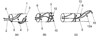
図1(a)から図1(c)には、図3に示す1本の二重に折り曲げた曲げ部を有する線材2を用いて、縮径させたステント1の縮径保持方法を示す。
図1(a)は、二重に折り曲げた曲げ部3を有する線材2を、縮径させたステント1の外周に1巻きさせている模式図である。ステントの外周に1巻されている線材の各部は、主部4、静端側線材6、動端側線材5、曲げ部3、曲げ部の輪7としている。
図1(b)は、ステント外周に巻かれた線材の主部4で動端側線材5を二重に折り曲げて曲げ部10を作成し、その動端側線材の曲げ部10を曲げ部3の輪7に通している模式図である。通過部12は、動端側線材5を二重に折り曲げて作成の曲げ部10を、曲げ部3の輪7を通過している線材であり、先端部分が曲げ部10である。
図1(c)は、図1(b)の通過部12の動端側線材5を引くことにより、通過部の長さを長くし通過部12aとしている模式図である。通過部12では、静端側線材を引かない。通過部12aの曲げ部10をさらに図1(a)の線材2の巻きつけ方向と同じ方向に1巻きさせ、通過部12aの主部の動端側線材を二重に折り曲げて新たに曲げ部Cを作成し、その曲げ部Cを通過部12aの曲げ部10の輪に通すこと、さらに図1(b)及び図1(c)を1回以上又は複数回繰り返すころにより、縮径されたステントを縮径保持させることができる。
図1(c)の曲げ部3の線材と通過部12aの静端側線材との交差部13は、曲げ部3の線材と通過部12aの静端側線材とは掛け結びの状態で交差している。
1 (a) to 1 (c) show a method for maintaining the reduced diameter of the
FIG. 1A is a schematic diagram in which a
FIG. 1B shows a
FIG.1 (c) is a schematic diagram which lengthens the length of the passage part and makes it the
The
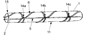
図2は、縮径保持されたステント1を線材2を用いて、図1(a)と図1(b)及び図1(c)の操作を複数回行い縮径保持されているステント11の一部を示す模式図である。図2では、線材2を用いて縮径保持されているステント11の各部は、基端側15とし、先端側は図2では示されていない。
ステントの外周に1巻きしている線材の主部の動端側線材を二重に折り曲げて曲げ部を作成し、その動端側線材の曲げ部を1巻きしている線材の曲げ部の輪に通す部分14a、14b、14cをステントの長さ方向に直線状に配置することにより、動端側線材はステントの長さ方向に、線材の曲げ部の輪に通す部分14a、14b、14cに沿って、直線状に設けることができる。直線状に設けられる動端側線材は、ステントを拡張させる場合に、抵抗が小さく、容易に拡張操作を行うことが出来る。
また、動端側線材5は、静端側線材6の下に設けられるために、屈曲した状態でもステント拡張時に動端側の端部を容易に引くことができる。
FIG. 2 shows the
The bending end of the wire rod in which the bending portion of the moving end side wire rod is wound once is created by bending the moving end side wire rod of the main portion of the wire rod wound around the stent twice. By arranging the
Moreover, since the moving
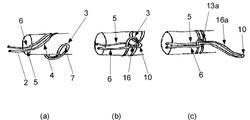
図4(a)から図4(c)には、図3に示す1本の二重に折り曲げた曲げ部を有する線材2を用いて、縮径させたステント1の縮径保持方法を示す。
図4(a)は、二重に折り曲げた曲げ部3を有する線材2を、縮径させたステント1の外周に1巻きさせている模式図である。ステントの外周に1巻されている線材の各部は、主部4、静端側線材6、動端側線材5、曲げ部3、曲げ部の輪7としている。
図4(b)は、ステント外周に巻かれた線材の主部4で、静端側線材6の下を線材2の曲げ部3をくぐらせ、その後、動端側線材5を二重に折り曲げて曲げ部10を作成し、その曲げ部10を曲げ部3の輪7に通している模式図である。通過部16は、動端側線材5の曲げ部3の輪7を通過している部分であり、先端部分が曲げ部10である。
図4(c)は、図4(b)の通過部16の動端側線材5を引くことにより、通過部16の長さを長くし通過部16aとしている模式図である。通過部16aの曲げ部10をさらに図4(a)の線材2の巻きつけ方向と同じ方向に1巻きさせ、通過部16aの主部の動端側線材を二重に折り曲げて新たに曲げ部を作成し、通過部16aの曲げ部10の輪に通すこと、さらに図4(b)及び図4(c)を1回以上又は複数回繰り返すことにより、縮径されたステントを縮径保持させることができる。
図4(c)の曲げ部3の線材と通過部16aの静端側線材との交差部13aは、曲げ部3の線材と通過部16aの静端側線材とは掛け結びの状態で交差している。
4 (a) to 4 (c) show a method for maintaining the reduced diameter of the
FIG. 4A is a schematic diagram in which the
FIG. 4 (b) shows the main part 4 of the wire wound around the outer periphery of the stent. Under the stationary
FIG. 4C is a schematic diagram in which the length of the
The
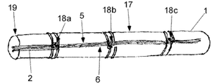
図5は、縮径保持されたステント1を線材2を用いて、図4(a)と、図4(b)及び図4(c)の操作を複数回行い縮径保持されているステント17の一部を示す模式図である。図2では、線材2を用いて縮径保持されているステント17の各部は、基端側19とし、先端側は図2では示されていない。
ステントの外周に1巻きしている線材の主部の動端側線材を二重に折り曲げて曲げ部を作成し、その動端側線材の曲げ部を1巻きしている線材の曲げ部の輪に通す部分18a、18b、18cをステントの長さ方向に直線状に配置することにより、動端側線材はステントの長さ方向に、線材の曲げ部の輪に通す部分18a、18b、18cに沿って、直線状に設けることができる。直線状に設けられる動端側線材は、ステントを拡張させる場合に、抵抗が小さく、容易に拡張操作を行うことが出来る。
また、動端側線材5は、静端側線材6の下に設けられるために、屈曲した状態でもステント拡張時に動端側の端部を容易に引くことができる。
FIG. 5 shows a
The bending end of the wire rod in which the bending portion of the moving end side wire rod is wound once is created by bending the moving end side wire rod of the main portion of the wire rod wound around the stent twice. By arranging the
Moreover, since the moving
本発明では、図1(b)及び図4(b)に示す結びを組み合わせて、縮径させたステントの縮径保持を行うことが出来る。 In the present invention, the reduced diameter of the reduced diameter stent can be maintained by combining the knots shown in FIGS. 1B and 4B.
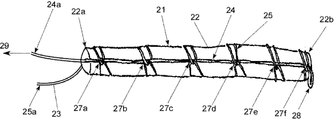
図6は、線材を1本用いて、図1(a)と、図1(b)及び図1(c)を複数回繰り返すことにより、ステントを縮径保持している縮径保持のステントの一例の模式図を示している。縮径保持されているステント21は、ステント22の先端側22bから基端側22aまで線材23により、縮径され、保持されている。線材23は、線材端部から曲げ部28までの一方を動端側線材24とし、他方の線材を静端側線材25とし、動端側線材の端部24aとし、静端側線材の端部25aとしている。
線材の曲げ部と静端側線材との交差部27a,27b,27c,27d,27e,27fは、曲げ部と静端側線材とは掛け結びの状態で交差している。交差部27a,27b,27c,27d,27e,27fは、ステントの長さ方向に直線状に設けることが好ましい。交差部を直線状に設けることにより、動端側線材が直線状になり、動端側線材の端部を引く抵抗が小さくなるために好ましい。交差部の間隔は、ステントの先端側から基端側まで、ほぼ等間隔に結ばれている。
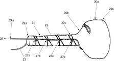
図7は、動端側線材の端部24aを矢印29方向にひくことにより、ステントの先端側の一部が拡張している模式図である。
動端側線材の端部24aを矢印29方向に引くことにより、ステント先端側の線材の交差部27fが最初に解くことができ、さらに交差部27eを解くことにより、先端側よりステントを拡張させることが出来る。さらに交差部27d、27c、27b、27aの順に線材を解くことにより、先端側よりステントを拡張させることができる。
ステントの拡張部30aとし、ステントの拡張し始めている部分30bとし、縮径されている部分30cとしている。
FIG. 6 shows a reduced diameter holding stent in which a single wire is used and FIG. 1 (a), FIG. 1 (b) and FIG. A schematic diagram of an example is shown. The
FIG. 7 is a schematic diagram in which a part of the distal end side of the stent is expanded by pulling the
By pulling the
The stent is an expanded
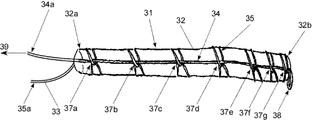
図8は、線材を1本用いて、図1(a)と、図1(b)及び図1(c)を複数回繰り返すことにより、ステントを縮径保持している縮径保持のステントの別の一例の模式図を示している。縮径保持されているステント31は、ステント32の先端側32bから基端側32aまで線材33により、縮径され、保持されている。線材33は、線材端部から曲げ部38までの一方を動端側線材34とし、他方の線材を静端側線材35とし、動端側線材の端部34aとし、静端側線材の端部35aとしている。
線材の曲げ部と静端側線材との交差部37a,37b,37c,37d,37e,37f,38gは、曲げ部と静端側線材とは掛け結びの状態で交差している。
交差部の間隔は、ステントの先端側に密な部分を、その他が基端側まで、ほぼ等間隔に結ばれている。
交差部の間隔は、ステントの先端側に密な部分を設けることにより先端側の交差部37gと線材の曲げ部38の解けの防止性が向上する。
動端側線材34の端部34aを矢印39方向に引くことにより、図7と同様にしてステントを拡張させることが出来る。交差部37a,37b,37c,37d,37e,37f,38gは、ステントの長さ方向に直線状に設けることが好ましい。交差部を直線状に設けることにより、動端側線材が直線状になり、動端側線材の端部を引く抵抗が小さくなるために好ましい。
FIG. 8 shows a reduced diameter holding stent in which a single wire is used and FIG. 1 (a), FIG. 1 (b) and FIG. The schematic diagram of another example is shown. The
The intervals between the crossing portions are connected at substantially equal intervals from the dense portion on the distal end side of the stent to the proximal end side in the other portions.
By providing a dense portion on the distal end side of the stent, the interval between the intersecting portions is improved in preventing the unraveling of the intersecting
By pulling the
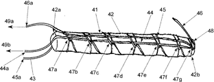
図9は、図6と同様に線材を1本用いて、図1(a)と、図1(b)及び図1(c)を複数回繰り返すことにより、ステントを縮径保持している縮径保持のステントの一例の模式図を示している。縮径保持されているステント41は、ステント42の先端側42bから基端側42aまで線材43により、縮径され、保持されている。線材43は、線材端部から曲げ部48までの一方を動端側線材44とし、他方の線材を静端側線材45とし、動端側線材の端部44aとし、静端側線材の端部45aとしている。
線材の曲げ部と静端側線材との交差部47a,47b,47c,47d,47e,47f,47gは、曲げ部と静端側線材とは掛け結びの状態で交差している。交差部47a,47b,47c,47d,47e,47f,47gは、ステントの長さ方向に直線状に設けることが好ましい。交差部を直線状に設けることにより、動端側線材が直線状になり、動端側線材の端部を引く抵抗が小さくなるために好ましい。交差部の間隔は、ステントの先端側から基端側まで、ほぼ等間隔に結ばれている。
線材の曲げ部48の輪に、新たな線材46を通している。曲げ部48の輪に線材46を通すことにより交差部47gの解けを防止させることができる。
線材46は、静端側線材45の下側に設けられている。
ステント42を拡張させる場合、線材46を矢印49bの方向に引き抜き、次に動端側線材の端部44aを矢印49aの方向に引くことにより、ステントの先端側より順次拡張させることが出来る。
FIG. 9 shows a reduction of the diameter of the stent held by reducing the diameter of the stent by repeating FIG. 1 (a), FIG. 1 (b) and FIG. 1 shows a schematic diagram of an example of a diameter-retaining stent. The
A
The
When the
図10には、図2に示す線材を用いて縮径保持されているステントの線材の外周に、カバー62を設けているカバー付き縮径保持されたステント61の一部を示す模式図である。カバーは、薄い透明なポリエチレン製である。
FIG. 10 is a schematic diagram showing a part of a
本発明の縮径保持されたステントは、その外周の一部又は全部にカバーを設けることにより、線材の交差部での解けを防止することができる。 The stent having a reduced diameter according to the present invention can be prevented from being unwound at the intersection of wire rods by providing a cover on a part or all of the outer periphery thereof.
本発明の縮径保持されたステントの拡張方法は、ステントの縮径保持に用いる線材の動端側の端部を引くことにより、ステントの先端側から順次拡張させることができる。 In the method for expanding a stent having a reduced diameter according to the present invention, the end of the wire used for maintaining the reduced diameter of the stent can be sequentially expanded from the distal end side of the stent.
ステントは、縮径可能なステントであればどのような構造の物でも用いることが出来る。
ステントとしては、ジグザグ状の線材からなる筒状構造体、1又は複数の線材の編物、織物又は組物、或いはこれらを複数組み合わせた筒状の構造体、金属製の筒状の構造体をレーザー加工などで加工した筒状構造体などを用いることが出来る。
ステントは自己拡張型のステントが好ましい。
Any stent can be used as long as the stent can be reduced in diameter.
As a stent, a cylindrical structure made of a zigzag wire, a knitted fabric of one or a plurality of wires, a woven fabric or a braid, or a cylindrical structure obtained by combining a plurality of these, a metal cylindrical structure is a laser. A cylindrical structure processed by processing or the like can be used.
The stent is preferably a self-expanding stent.
ステントに用いる線材及び金属製の筒状の構造体の材料としては、ステンレス、タンタル、チタン、白金、金、タングステンなど、Ni−Ti系、Cu−Al−Ni系、Cu−Zn−Al系などの形状記憶合金などの金属線材などを用いることが出来る。用いる金属の表面に金、白金などをメッキ等の手段で被覆したものも用いることが出来る。
ステントに用いる線材及び金属製の筒状の構造体の材料としては、熱処理による形状記憶効果や、超弾性が付与される形状記憶合金を好ましく用いることが出来る。
ステントに用いる線材の太さは、特に限定されないが、例えば血管用ステント等の場合には、0.08〜1mmが好ましい。
ステントに用いる金属製の筒状の構造体の厚さは、特に限定されないが、例えば血管用ステント等の場合には、0.08〜1mmが好ましい。
Examples of the material of the wire rod and metal cylindrical structure used for the stent include stainless steel, tantalum, titanium, platinum, gold, tungsten, Ni-Ti, Cu-Al-Ni, Cu-Zn-Al, etc. A metal wire such as a shape memory alloy can be used. It is also possible to use a metal surface that is coated with gold, platinum or the like by means such as plating.
As a material for the wire rod and metal cylindrical structure used for the stent, a shape memory alloy to which a shape memory effect by heat treatment or superelasticity is imparted can be preferably used.
Although the thickness of the wire used for a stent is not specifically limited, For example, in the case of a blood vessel stent etc., 0.08-1 mm is preferable.
Although the thickness of the metal cylindrical structure used for the stent is not particularly limited, for example, in the case of a blood vessel stent or the like, 0.08 to 1 mm is preferable.
ステントは、ステントの外面、内面、又は外面と内面の両面に、筒状カバーを設けることができる。
筒状カバーは、ステントの外周、内周、又は外周と内周の両側、好ましくは外周、内周、又は外周と内周の両側の全面に設けることが出来る。
筒状カバーは、ステントの縮径形状及び拡張形状に追従可能なものであり、柔らかいチューブ、織物、編物などが好ましい。
The stent can be provided with a cylindrical cover on the outer surface, the inner surface, or both the outer surface and the inner surface of the stent.
The cylindrical cover can be provided on the outer periphery, inner periphery, or both sides of the outer periphery and the inner periphery, preferably on the outer periphery, the inner periphery, or the entire surface on both sides of the outer periphery and the inner periphery.
The cylindrical cover can follow the reduced diameter shape and the expanded shape of the stent, and is preferably a soft tube, woven fabric, knitted fabric, or the like.
筒状カバーは、熱可塑性樹脂を押出し成形、ブロー成形などの成形方法で円筒状に形成したもの、円筒状に形成した熱可塑性樹脂の繊維の編織物、円筒状に形成した熱可塑性樹脂の不織布、円筒状に形成した可擁性樹脂のシートや多孔質シートなどを用いることができる。さらに、編織物としては、平織、綾織などの公知の編物や織物を用いることができる。
また筒状カバーは、クリンプ加工などのヒダの付いたものを使用することもできる。
筒状カバーは、継ぎ目のない筒状の構造体であることが好ましい。
筒状カバーは、公知の人工血管などを用いることが出来る。
The cylindrical cover is formed by forming a thermoplastic resin into a cylindrical shape by extrusion molding, blow molding, or the like, a knitted fabric of thermoplastic resin fibers formed into a cylindrical shape, or a thermoplastic resin nonwoven fabric formed into a cylindrical shape. A cylindrical resin sheet, a porous resin sheet, or the like can be used. Furthermore, as the knitted fabric, known knitted fabrics and woven fabrics such as plain weave and twill weave can be used.
In addition, a cylindrical cover with a crease such as crimping can be used.
The tubular cover is preferably a seamless tubular structure.
A well-known artificial blood vessel etc. can be used for a cylindrical cover.
筒状カバーは、特に円筒状に形成した熱可塑性樹脂の樹脂繊維の編織物、さらに円筒状に形成した熱可塑性樹脂の樹脂繊維の平織の織物が、強度及び有孔度、生産性に優れるために好ましい。 The cylindrical cover is particularly excellent in strength, porosity, and productivity because the knitted fabric of thermoplastic resin fibers formed in a cylindrical shape and the plain weave fabric of thermoplastic resin fibers formed in a cylindrical shape are excellent. Is preferable.
筒状カバーは、ステントの一部又は全部に接続させることができる。筒状カバーをステントに連結させる方法としては、縫い付ける方法、接着剤を用いて付ける方法、熱可塑性樹脂などでは融着させる方法などを挙げることが出来る。 The cylindrical cover can be connected to part or all of the stent. Examples of the method of connecting the cylindrical cover to the stent include a method of sewing, a method of using an adhesive, and a method of fusing with a thermoplastic resin.
筒状カバーの材質は、ポリエチレン、ポリプロピレン、エチレン・α−オレフイン共重合体などのポリオレフィン、ポリアミド、ポリウレタン、ポリエチレンテレフタレート、ポリブチレンテレフタレート、ポリシクロヘキサンテレフタレート、ポリエテレン−2,6−ナフタレートなどのポリエステル、ポリ弗化エチレンやポリ弗化プロピレンなどのフッ素樹脂、シリコーン、ポリ乳酸、ポリグリコール酸、ポリウレタンなどの熱可塑性樹脂及びこれらの樹脂繊維を用いることが出来る。
特に筒状カバーの材質は、化学的に安定で耐久性が大きく、組織反応の少ない、ポリエチレンテレフタレートなどのポリエステル、ポリ弗化エチレンやポリ弗化プロピレンなどのフッ素樹脂及びこれらの樹脂繊維を好ましく用いることができる。
The material of the cylindrical cover is polyolefin such as polyethylene, polypropylene, ethylene / α-olefin copolymer, polyamide, polyurethane, polyethylene terephthalate, polybutylene terephthalate, polycyclohexane terephthalate, polyester such as polyethylene-2,6-naphthalate, poly Fluorine resins such as fluorinated ethylene and polyfluorinated propylene, thermoplastic resins such as silicone, polylactic acid, polyglycolic acid, and polyurethane, and resin fibers thereof can be used.
In particular, the material of the cylindrical cover is preferably a chemically stable and highly durable polyester resin such as polyethylene terephthalate, a fluororesin such as polyfluorinated ethylene or polyfluorinated propylene, and these resin fibers. be able to.
樹脂繊維としては、紡糸可能な円形、楕円、U型、中空状、リボン状、断面が円形や楕円形ではない異径などの形状で、紡糸可能な太さの糸を用いることができ、0.01〜5デニール、さらに0.1〜3デニール、特に0.8を超えて3デニール以下のモノフィラメント数〜数百本、さらに10〜700本、特に10〜100本を撚った糸や束ねた糸を用いることが出来る。 As the resin fiber, a spinnable, circular, elliptical, U-shaped, hollow, ribbon-like, cross-sectional shape with a different diameter other than circular or elliptical, and a thickness capable of spinning can be used. .01 to 5 denier, further 0.1 to 3 denier, especially more than 0.8 to 3 denier monofilament number to several hundred, further 10 to 700, especially 10 to 100 twisted yarn or bundle Can be used.
筒状カバーの有孔度は、ステントの使用を損なわないものであれば特に制限なく用いることが出来るが、0〜3000[ml/(cm2・min・120mmHg)、37℃]であることが好ましい。
筒状カバーの壁厚は、ステントの使用を損なわないものであれば特に制限なく用いることが出来るが、30〜2000μmであることが好ましい。
筒状カバーは、ステントと、1又は複数の部分で固定されていてもよい。
The porosity of the cylindrical cover can be used without particular limitation as long as it does not impair the use of the stent, but is 0 to 3000 [ml / (cm 2 · min · 120 mmHg), 37 ° C.]. preferable.
The wall thickness of the cylindrical cover can be used without particular limitation as long as it does not impair the use of the stent, but is preferably 30 to 2000 μm.
The cylindrical cover may be fixed to the stent at one or more portions.
筒状カバー、筒状カバーを構成する樹脂繊維など及びステントを構成する線材や金属製の筒状の構造体は、ヘパリン、コラーゲン、アセチルサリチル酸、ゼラチンなどの生体適合性のある材料で被覆処理されているものを用いることができる。 The cylindrical cover, the resin fibers that make up the cylindrical cover, and the wire and metal tubular structures that make up the stent are coated with a biocompatible material such as heparin, collagen, acetylsalicylic acid, and gelatin. Can be used.
線材は、本発明の特性を損なわないものであればよく、素材、形状及び太さなどは適宜選択して用いることが出来る。
線材に用いる素材としては、上記の筒状カバー、筒状カバーを構成する樹脂繊維、ステントを構成する線材などの合成樹脂や金属などを用いることが出来る。
The wire may be any wire that does not impair the characteristics of the present invention, and the material, shape, thickness, and the like can be appropriately selected and used.
As a material used for the wire, synthetic resin such as the above-described cylindrical cover, resin fiber constituting the cylindrical cover, wire constituting the stent, metal, or the like can be used.
線材の形状は、本発明の特性を損なわないものであればどのようなものでも用いることができ、例えば、線状、チューブ状、帯状、板状などをもちいることができる。
線材は、モノフィラメント、マルチフィラメント及び/又は樹脂繊維など、さらにこれらの織物、編物、組み物、複数束ねたものなどを用いることができる。
Any wire can be used as long as it does not impair the characteristics of the present invention. For example, the wire, tube, belt, plate, or the like can be used.
As the wire, monofilaments, multifilaments and / or resin fibers, etc., and these woven fabrics, knitted fabrics, braided fabrics, and bundles of a plurality of these can be used.
線材の材質としては、ポリエチレン、ポリプロピレン、エチレン・α−オレフイン共重合体などのポリオレフィン、ポリアミド、ポリウレタン、ポリエチレンテレフタレート、ポリブチレンテレフタレート、ポリシクロヘキサンテレフタレート、ポリエテレン−2,6−ナフタレートなどのポリエステル、ポリ弗化エチレンやポリ弗化プロピレンなどのフッ素樹脂、シリコーン、ポリ乳酸、ポリグリコール酸、ポリウレタンなどの熱可塑性樹脂や熱硬化性樹脂など及びこれらの樹脂繊維を用いることが出来る。
特に線材の材質は、化学的に安定で耐久性が大きく、組織反応の少ない、ポリエチレンテレフタレートなどのポリエステル、ポリ弗化エチレンやポリ弗化プロピレンなどのフッ素樹脂及びこれらの樹脂繊維を好ましく用いることができる。
Examples of the wire material include polyolefins such as polyethylene, polypropylene, ethylene / α-olefin copolymer, polyamide, polyurethane, polyethylene terephthalate, polybutylene terephthalate, polycyclohexane terephthalate, polyester such as polyethylene-2,6-naphthalate, and polyfluoride. Fluorine resins such as fluorinated ethylene and polyfluorinated propylene, thermoplastic resins such as silicone, polylactic acid, polyglycolic acid, and polyurethane, thermosetting resins, and these resin fibers can be used.
In particular, the material of the wire is preferably chemically stable and highly durable, with little tissue reaction, polyester such as polyethylene terephthalate, fluororesin such as polyfluorinated ethylene or polyfluorinated propylene, and these resin fibers. it can.
縮径保持されたステントの外周に、さらにカバーを設けることにより、線材の解けを防止することが出来、シースなどに容易に挿入でき、摩擦力低減のために好ましい。
カバーは、筒状、袋状などステントの外周の一部又は全部を覆うものを用いることが出来る。
カバーは、厚みの薄いものが好ましく、厚みが好ましくは1000μ以下、さらに好ましくは600μm以下、より好ましくは100μm以下、特に好ましくは50μm以下のものを用いることが、屈曲の追従性などに優れるために好ましい。
特にカバーの材質は、ポリエチレン、ポリプロピレン、エチレン・α−オレフイン共重合体などのポリオレフィン、ポリアミド、ポリウレタン、ポリエチレンテレフタレート、ポリブチレンテレフタレート、ポリシクロヘキサンテレフタレート、ポリエテレン−2,6−ナフタレートなどのポリエステル、ポリ弗化エチレンやポリ弗化プロピレンなどのフッ素樹脂、シリコーン、ポリ乳酸、ポリグリコール酸、ポリウレタンなどの熱可塑性樹脂を用いることが出来る。
特にカバーは、ポリエチレン、ポリプロピレン、エチレン・α−オレフイン共重合体などのポリオレフィンを用いることにより、屈曲の追従性、表面の平滑性、生体に対しての安全性が高いために好ましい。
カバーは透明や不透明などどのようなものでも用いることが出来るが、特に透明なカバーは視認性に優れるために好ましい。
By further providing a cover on the outer circumference of the stent having a reduced diameter, it is possible to prevent the wire from being unwound, and it can be easily inserted into a sheath or the like, which is preferable for reducing the frictional force.
As the cover, a cover that covers a part or all of the outer periphery of the stent, such as a cylindrical shape or a bag shape, can be used.
The cover preferably has a small thickness, and preferably has a thickness of 1000 μm or less, more preferably 600 μm or less, more preferably 100 μm or less, and particularly preferably 50 μm or less. preferable.
In particular, the cover is made of polyolefin such as polyethylene, polypropylene, ethylene / α-olefin copolymer, polyamide, polyurethane, polyethylene terephthalate, polybutylene terephthalate, polycyclohexane terephthalate, polyester such as polyethylene-2,6-naphthalate, and polyfluoride. Fluorine resins such as fluorinated ethylene and polyfluorinated propylene, and thermoplastic resins such as silicone, polylactic acid, polyglycolic acid, and polyurethane can be used.
In particular, the cover is preferably made of a polyolefin such as polyethylene, polypropylene, or ethylene / α-olefin copolymer because it has high flexibility in bending, smoothness on the surface, and high safety to living bodies.
Any cover such as transparent or opaque can be used, but a transparent cover is particularly preferable because of its excellent visibility.
本発明の縮径保持されたステントは、シースやカテーテルに挿入して用いることが出来る。
本発明の縮径保持されたステントの内側にシースを設けることが出来る。
The stent having a reduced diameter according to the present invention can be used by being inserted into a sheath or a catheter.
A sheath can be provided inside the stent having a reduced diameter according to the present invention.
ステント、筒状カバー、カバー及び線材は、適当な場所、例えばステント、カバーや筒状カバーの両端部、線材の静端側、動端側又は曲げ部などには、X線不透過材料が回着されていてもよい。X線不透過材料としては、例えば金、白金、イリジウム、タンタル、タングステン、銀などや、それらを含有する合金などが好ましく使用される。X線不透過材料は、ステントに半田付け、ろう付け、溶着、接着、カシメなどの手段で固着することができる。 The stent, cylindrical cover, cover, and wire are made of X-ray-impermeable material at appropriate locations, for example, at both ends of the stent, cover or cylindrical cover, at the static end, at the moving end, or at the bent portion of the wire. It may be worn. As the X-ray opaque material, for example, gold, platinum, iridium, tantalum, tungsten, silver, or an alloy containing them is preferably used. The radiopaque material can be fixed to the stent by means of soldering, brazing, welding, adhesion, caulking, or the like.
本発明は、例えば血管、尿管、胆管、気管などの人体の管状器官に挿入し、配置されるステントの縮径保持方法と、その縮径保持方法を用いて縮径保持された縮径保持ステントである。 The present invention relates to a method for maintaining a reduced diameter of a stent that is inserted and disposed in a tubular organ of a human body such as a blood vessel, a ureter, a bile duct, and a trachea, and a reduced diameter held by using the reduced diameter holding method. It is a stent.
1,22,32,42:ステント、
2.23,33,43:線材、
3,10,28,38,48:線材の曲げ部、
4:ステントの外周に巻かれた線材の主部、
5,24,34,44:動端側線材、
6,25,35,45:静端側線材、
7:線材の曲げ部の輪、
11,17,21,31,41:縮径保持されたステント、
12,16:動端側線材の曲げ部の通過部、
14a,14b,14c,18a,18b,18c:交差部、
61:カバー付き縮径保持されたステント、
62:カバー。
1, 22, 32, 42: stent,
2.23, 33, 43: Wire,
3, 10, 28, 38, 48: bending portion of wire,
4: The main part of the wire wound around the outer periphery of the stent,
5, 24, 34, 44: Moving end side wire,
6, 25, 35, 45: Static end side wire,
7: Ring of bent part of wire,
11, 17, 21, 31, 41: stents with a reduced diameter,
12, 16: Passing portion of the bent portion of the moving end side wire,
14a, 14b, 14c, 18a, 18b, 18c: intersection,
61: Reduced diameter retained stent with cover,
62: Cover.
Claims (4)
(1)二重に折り曲げた曲げ部Aを有する線材を縮径させたステントの外周に1巻きし、ステント外周に巻かれた主部の動端側線材を二重に折り曲げて、曲げ部Aの輪に通す、
(2)曲げ部の輪を通した動端側線材を二重に折り曲げて曲げ部Bを作成し、この曲げ部Bを有する二重に折り曲げた動端側線材を上記(1)の線材と同じ巻き方向に縮径させたステントの外周に1巻きし、ステント外周に巻かれた主部の動端側線材を二重に折り曲げて、曲げ部Bの輪に通す、
さらに上記(2)を1回以上繰り返すことにより縮径させたステントの縮径を保持することを特徴とするステントの縮径保持方法。 It is a reduced diameter holding method for holding the reduced diameter of a stent that has been reduced in diameter using a wire,
(1) A wire having a bent portion A bent twice is wound around the outer circumference of a stent having a reduced diameter, and the main moving end side wire wound around the outer periphery of the stent is bent twice to bend the bent portion A. Through the ring of
(2) The bending end B is formed by bending the moving end side wire rod that has passed through the ring of the bending portion, and the bending end portion B having the bending portion B is formed as the moving end side wire rod with the wire rod of the above (1). One turn on the outer circumference of the stent reduced in diameter in the same winding direction, the double end of the main moving end side wire wound around the outer circumference of the stent is bent and passed through the ring of the bent portion B.
Furthermore, the reduced diameter holding method of the stent characterized by holding the reduced diameter of the stent which has been reduced in diameter by repeating the above (2) at least once.
二重に折り曲げた曲げ部Aを有する線材の動端側線材の端部又は端部近傍を引くことにより縮径保持されたステントを拡張させることを特徴とする縮径保持されたステントの拡張方法。
A method for expanding a stent having a reduced diameter according to claim 2,
A method for expanding a stent having a reduced diameter, wherein the stent having a reduced diameter is expanded by pulling an end portion or a vicinity of the end portion of a wire rod having a bent portion A that is bent twice. .
Priority Applications (1)
| Application Number | Priority Date | Filing Date | Title |
|---|---|---|---|
| JP2004126186A JP4376112B2 (en) | 2004-04-22 | 2004-04-22 | Reduced diameter stent |
Applications Claiming Priority (1)
| Application Number | Priority Date | Filing Date | Title |
|---|---|---|---|
| JP2004126186A JP4376112B2 (en) | 2004-04-22 | 2004-04-22 | Reduced diameter stent |
Publications (2)
| Publication Number | Publication Date |
|---|---|
| JP2005304792A true JP2005304792A (en) | 2005-11-04 |
| JP4376112B2 JP4376112B2 (en) | 2009-12-02 |
Family
ID=35434227
Family Applications (1)
| Application Number | Title | Priority Date | Filing Date |
|---|---|---|---|
| JP2004126186A Expired - Fee Related JP4376112B2 (en) | 2004-04-22 | 2004-04-22 | Reduced diameter stent |
Country Status (1)
| Country | Link |
|---|---|
| JP (1) | JP4376112B2 (en) |
Cited By (2)
| Publication number | Priority date | Publication date | Assignee | Title |
|---|---|---|---|---|
| US11191632B2 (en) | 2016-11-10 | 2021-12-07 | Cook Medical Technologies Llc | Temporary diameter reduction constraint arrangement for a stent graft in combination with a stent graft |
| JP2022532584A (en) * | 2019-05-10 | 2022-07-15 | ダブリュ.エル.ゴア アンド アソシエイツ,インコーポレイティド | Restraint mechanism for selective deployment and related methods |
Citations (4)
| Publication number | Priority date | Publication date | Assignee | Title |
|---|---|---|---|---|
| US5405378A (en) * | 1992-05-20 | 1995-04-11 | Strecker; Ernst P. | Device with a prosthesis implantable in the body of a patient |
| JP2000503559A (en) * | 1995-12-14 | 2000-03-28 | ゴア エンタープライズ ホールディングス,インコーポレイティド | Apparatus and method for deploying a stent-graft |
| JP2001506902A (en) * | 1996-12-23 | 2001-05-29 | ゴア エンタープライズ ホールディングス,インコーポレイティド | Implant deployment device |
| JP2001518367A (en) * | 1997-10-03 | 2001-10-16 | アプライド・メディカル・テクノロジー・インコーポレーテッド | Gastric fistula forming device and method of assembling the same |
-
2004
- 2004-04-22 JP JP2004126186A patent/JP4376112B2/en not_active Expired - Fee Related
Patent Citations (4)
| Publication number | Priority date | Publication date | Assignee | Title |
|---|---|---|---|---|
| US5405378A (en) * | 1992-05-20 | 1995-04-11 | Strecker; Ernst P. | Device with a prosthesis implantable in the body of a patient |
| JP2000503559A (en) * | 1995-12-14 | 2000-03-28 | ゴア エンタープライズ ホールディングス,インコーポレイティド | Apparatus and method for deploying a stent-graft |
| JP2001506902A (en) * | 1996-12-23 | 2001-05-29 | ゴア エンタープライズ ホールディングス,インコーポレイティド | Implant deployment device |
| JP2001518367A (en) * | 1997-10-03 | 2001-10-16 | アプライド・メディカル・テクノロジー・インコーポレーテッド | Gastric fistula forming device and method of assembling the same |
Cited By (4)
| Publication number | Priority date | Publication date | Assignee | Title |
|---|---|---|---|---|
| US11191632B2 (en) | 2016-11-10 | 2021-12-07 | Cook Medical Technologies Llc | Temporary diameter reduction constraint arrangement for a stent graft in combination with a stent graft |
| US11911260B2 (en) | 2016-11-10 | 2024-02-27 | Cook Medical Technologies Llc | Temporary diameter reduction constraint arrangement for a stent graft in combination with a stent graft |
| JP2022532584A (en) * | 2019-05-10 | 2022-07-15 | ダブリュ.エル.ゴア アンド アソシエイツ,インコーポレイティド | Restraint mechanism for selective deployment and related methods |
| JP7295975B2 (en) | 2019-05-10 | 2023-06-21 | ダブリュ.エル.ゴア アンド アソシエイツ,インコーポレイティド | Restraint Mechanisms and Associated Methods for Selective Deployment |
Also Published As
| Publication number | Publication date |
|---|---|
| JP4376112B2 (en) | 2009-12-02 |
Similar Documents
| Publication | Publication Date | Title |
|---|---|---|
| JP4627687B2 (en) | Stent insertion device | |
| CN103200884B (en) | For affecting the implant of the blood flow in arteriovenous malformotion | |
| US20180049898A1 (en) | Stent having flexibly connected adjacent stent elements | |
| US5674276A (en) | Tubular medical prosthesis | |
| JP5688019B2 (en) | Stent with stranded wire | |
| JP3280034B2 (en) | Stent graft against kink | |
| JP2001506176A (en) | Sandwich stent | |
| JP2004049585A (en) | Stent type therapeutic instrument | |
| EP2769699A1 (en) | Attachment of stent to graft fabric with an anchoring machine stitching | |
| JP2020036905A (en) | Stent graft | |
| JP2005270432A (en) | Method of holding stent in reduced diameter state and stent held in reduced diameter state | |
| KR20170120657A (en) | Stent graft | |
| JP7048096B2 (en) | Stent graft with fenestration part | |
| JP2004049806A (en) | Stent and graft with stent | |
| US20040186549A1 (en) | Braided stent with looped ends and method for making same | |
| JP4376112B2 (en) | Reduced diameter stent | |
| JP4608672B2 (en) | Stented graft | |
| JP4429833B2 (en) | Stent and stent graft | |
| JP2005245985A (en) | Stent with tubular cover, which is held in reduced diameter state and reduced diameter-holding method | |
| JP2003088591A (en) | Stent and graft with stent | |
| US20210259861A1 (en) | Stent | |
| JP7277988B2 (en) | Stent graft with fenestration | |
| JP4494144B2 (en) | Tubular organ treatment tool | |
| JP2005058459A (en) | Reduced diameter holding method of stent graft | |
| JP2003079743A (en) | Stent and graft with stent |
Legal Events
| Date | Code | Title | Description |
|---|---|---|---|
| A621 | Written request for application examination |
Free format text: JAPANESE INTERMEDIATE CODE: A621 Effective date: 20060913 |
|
| A977 | Report on retrieval |
Free format text: JAPANESE INTERMEDIATE CODE: A971007 Effective date: 20081127 |
|
| A131 | Notification of reasons for refusal |
Free format text: JAPANESE INTERMEDIATE CODE: A131 Effective date: 20090217 |
|
| A711 | Notification of change in applicant |
Free format text: JAPANESE INTERMEDIATE CODE: A711 Effective date: 20090407 |
|
| RD02 | Notification of acceptance of power of attorney |
Free format text: JAPANESE INTERMEDIATE CODE: A7422 Effective date: 20090407 |
|
| A521 | Request for written amendment filed |
Free format text: JAPANESE INTERMEDIATE CODE: A523 Effective date: 20090416 |
|
| A521 | Request for written amendment filed |
Free format text: JAPANESE INTERMEDIATE CODE: A821 Effective date: 20090407 |
|
| A521 | Request for written amendment filed |
Free format text: JAPANESE INTERMEDIATE CODE: A821 Effective date: 20090416 |
|
| A131 | Notification of reasons for refusal |
Free format text: JAPANESE INTERMEDIATE CODE: A131 Effective date: 20090609 |
|
| A521 | Request for written amendment filed |
Free format text: JAPANESE INTERMEDIATE CODE: A523 Effective date: 20090807 |
|
| TRDD | Decision of grant or rejection written | ||
| A01 | Written decision to grant a patent or to grant a registration (utility model) |
Free format text: JAPANESE INTERMEDIATE CODE: A01 Effective date: 20090901 |
|
| A01 | Written decision to grant a patent or to grant a registration (utility model) |
Free format text: JAPANESE INTERMEDIATE CODE: A01 |
|
| A61 | First payment of annual fees (during grant procedure) |
Free format text: JAPANESE INTERMEDIATE CODE: A61 Effective date: 20090908 |
|
| R150 | Certificate of patent or registration of utility model |
Ref document number: 4376112 Country of ref document: JP Free format text: JAPANESE INTERMEDIATE CODE: R150 Free format text: JAPANESE INTERMEDIATE CODE: R150 |
|
| FPAY | Renewal fee payment (event date is renewal date of database) |
Free format text: PAYMENT UNTIL: 20120918 Year of fee payment: 3 |
|
| FPAY | Renewal fee payment (event date is renewal date of database) |
Free format text: PAYMENT UNTIL: 20120918 Year of fee payment: 3 |
|
| FPAY | Renewal fee payment (event date is renewal date of database) |
Free format text: PAYMENT UNTIL: 20130918 Year of fee payment: 4 |
|
| R250 | Receipt of annual fees |
Free format text: JAPANESE INTERMEDIATE CODE: R250 |
|
| R250 | Receipt of annual fees |
Free format text: JAPANESE INTERMEDIATE CODE: R250 |
|
| R250 | Receipt of annual fees |
Free format text: JAPANESE INTERMEDIATE CODE: R250 |
|
| R250 | Receipt of annual fees |
Free format text: JAPANESE INTERMEDIATE CODE: R250 |
|
| R250 | Receipt of annual fees |
Free format text: JAPANESE INTERMEDIATE CODE: R250 |
|
| S111 | Request for change of ownership or part of ownership |
Free format text: JAPANESE INTERMEDIATE CODE: R313111 |
|
| R350 | Written notification of registration of transfer |
Free format text: JAPANESE INTERMEDIATE CODE: R350 |
|
| R250 | Receipt of annual fees |
Free format text: JAPANESE INTERMEDIATE CODE: R250 |
|
| R250 | Receipt of annual fees |
Free format text: JAPANESE INTERMEDIATE CODE: R250 |
|
| R250 | Receipt of annual fees |
Free format text: JAPANESE INTERMEDIATE CODE: R250 |
|
| R250 | Receipt of annual fees |
Free format text: JAPANESE INTERMEDIATE CODE: R250 |
|
| R250 | Receipt of annual fees |
Free format text: JAPANESE INTERMEDIATE CODE: R250 |
|
| LAPS | Cancellation because of no payment of annual fees |