JP2005304619A - Dishwasher - Google Patents
Dishwasher Download PDFInfo
- Publication number
- JP2005304619A JP2005304619A JP2004123088A JP2004123088A JP2005304619A JP 2005304619 A JP2005304619 A JP 2005304619A JP 2004123088 A JP2004123088 A JP 2004123088A JP 2004123088 A JP2004123088 A JP 2004123088A JP 2005304619 A JP2005304619 A JP 2005304619A
- Authority
- JP
- Japan
- Prior art keywords
- water
- heat source
- water supply
- cleaning
- heater
- Prior art date
- Legal status (The legal status is an assumption and is not a legal conclusion. Google has not performed a legal analysis and makes no representation as to the accuracy of the status listed.)
- Pending
Links
Images


Classifications
-
- Y—GENERAL TAGGING OF NEW TECHNOLOGICAL DEVELOPMENTS; GENERAL TAGGING OF CROSS-SECTIONAL TECHNOLOGIES SPANNING OVER SEVERAL SECTIONS OF THE IPC; TECHNICAL SUBJECTS COVERED BY FORMER USPC CROSS-REFERENCE ART COLLECTIONS [XRACs] AND DIGESTS
- Y02—TECHNOLOGIES OR APPLICATIONS FOR MITIGATION OR ADAPTATION AGAINST CLIMATE CHANGE
- Y02B—CLIMATE CHANGE MITIGATION TECHNOLOGIES RELATED TO BUILDINGS, e.g. HOUSING, HOUSE APPLIANCES OR RELATED END-USER APPLICATIONS
- Y02B40/00—Technologies aiming at improving the efficiency of home appliances, e.g. induction cooking or efficient technologies for refrigerators, freezers or dish washers
Abstract
Description
本発明は、蒸気発生機能を有する食器洗浄機に関する。 The present invention relates to a dishwasher having a steam generating function.
家庭用の食器洗浄機は、洗浄槽内に貯留された洗浄水を洗浄ポンプで汲み上げ、噴射ノズルから噴射させることにより食器の汚れを洗い落とすようになっている。また、食器にこびりついた汚れでも噴射ノズルから噴射された洗浄水によって洗い落とすことができるように、スチーム工程と称する予洗工程を洗浄工程の前に実行する食器洗浄機が提案されている。 Household dishwashers use a washing pump to pump up washing water stored in a washing tank and spray it from an injection nozzle to wash away stains on tableware. In addition, a dishwasher has been proposed in which a pre-washing process called a steam process is executed before the washing process so that dirt stuck to the tableware can be washed away by washing water jetted from the jet nozzle.
スチーム工程では、洗浄槽や洗浄槽に設けられた貯水容器に貯留された水をヒータで加熱することにより蒸気を生成させ、前記食器にこびりついた汚れを膨潤するようになっている。
ところが、従来の食器洗浄機では、ヒータを水没させた状態で前記ヒータに通電するように構成されている。従って、蒸気を生成させるためには、洗浄槽や貯水容器に貯留された水の全体が100℃近くになるまでヒータを通電しなければならない。このため、蒸気生成量に比べて多量の水を加熱する必要があり、その分、加熱エネルギーが無駄になったり加熱時間が長くなったりするという問題があった。 However, the conventional dishwasher is configured to energize the heater while the heater is submerged. Therefore, in order to generate steam, the heater must be energized until the total amount of water stored in the washing tank or the water storage container is close to 100 ° C. For this reason, it is necessary to heat a large amount of water compared to the amount of steam generated, and there is a problem that the heating energy is wasted and the heating time is lengthened accordingly.
本発明は上記事情に鑑みてなされたものであり、その目的は、蒸気生成に必要な加熱エネルギーを小さく抑えて加熱時間の短縮化を図ることができる食器洗浄機を提供することである。 This invention is made | formed in view of the said situation, The objective is to provide the dishwasher which can aim at shortening of heating time, suppressing the heating energy required for vapor | steam production | generation small.
本発明の食器洗浄機は、食器を収容する洗浄槽、前記洗浄槽内に配置された熱源、前記洗浄槽内に給水する給水装置を有し前記給水装置によって前記洗浄槽内に供給される水を前記熱源に誘導して接触させる水誘導手段を備えており、蒸気生成手段は、前記給水装置、前記熱源及び前記水誘導手段を制御することにより蒸気を生成するように構成されている。 The dishwasher according to the present invention has a washing tank for storing tableware, a heat source disposed in the washing tank, a water supply device for supplying water into the washing tank, and water supplied into the washing tank by the water supply device. Is provided with water guiding means that guides and contacts the heat source, and the steam generating means is configured to generate steam by controlling the water supply device, the heat source, and the water guiding means.
この場合、熱源と水とを接触させる方法としては、食器に洗浄槽を吹き付けるためのポンプ手段及び噴射ノズルを利用し、前記噴射ノズルから噴射される水を熱源に誘導して接触させる方法、給水口から洗浄槽内に流出する水を熱源まで誘導して前記熱源と接触させる方法などが考えられる。 In this case, as a method of bringing the heat source into contact with water, a pump means and spray nozzles for spraying the washing tub on the tableware, and a method of inducing and contacting water sprayed from the spray nozzle to the heat source, water supply A method of inducing water flowing out of the mouth into the washing tank to a heat source and bringing it into contact with the heat source is conceivable.
本発明では、洗浄槽内に供給される水を熱源に接触させて前記水を加熱する。つまり、蒸気を生成するときに熱源を水中に浸漬させずに、蒸気生成に必要な水を熱源に接触させ、その水を熱源によって加熱するようにしている。このため、熱源によって加熱される水の量を極力少なくすることができ、水を蒸発させるために必要な加熱時間の短縮化を図ることができる。 In this invention, the water supplied in a washing tank is made to contact a heat source, and the said water is heated. That is, when the steam is generated, the heat source is not immersed in the water, but the water necessary for generating the steam is brought into contact with the heat source, and the water is heated by the heat source. For this reason, the amount of water heated by the heat source can be reduced as much as possible, and the heating time necessary for evaporating the water can be shortened.
以下、本発明を家庭用の食器洗浄機に適用したいくつかの実施例について説明する。
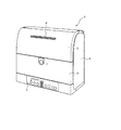
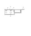
図1ないし図6は本発明の第1の実施例を示している。図1ないし図3において、食器洗浄機1は内部に洗浄槽2を有する洗浄機本体3、前記洗浄機本体3の前面に設けられ前記洗浄槽2の前部開口を開閉するための下部扉4及び上部扉5、前記下部扉4の下部に設けられた操作パネル6を備えて構成されている。前記操作パネル6には、各種のスイッチや表示部等が設けられている。
Several embodiments in which the present invention is applied to a household dishwasher will be described below.
1 to 6 show a first embodiment of the present invention. 1 to 3, a dishwasher 1 includes a washing machine body 3 having a
前記扉4,5は、それぞれ上端部及び下端部において洗浄機本体3に軸支されており、図示しないリンク機構を介して連動して回動するように構成されている。前記下部扉4の前面には扉4,5を開放させるための押ボタン7が設けられている。両扉4,5は、前記押ボタン7を押圧操作し、前記下部扉4を手前に引き下げることにより開放されるようになっている。また、前記上部扉5には、前記洗浄槽2内の水蒸気を排出するための排気口8が設けられている。
The
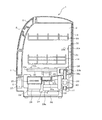
洗浄槽2の内部には上下2個の食器かご18,19が出し入れ可能に収容されている。また、洗浄槽2内の奥部には噴射ノズル20が固定されている。前記噴射ノズル20は、洗浄槽2の内面に沿って左右に延びる帯状の中空部材20aとその前面に形成された複数の噴射孔20bから構成されている。中空部材20aの途中部には洗浄槽2の下部まで延びる筒状部21が一体的に設けられている。更に、洗浄槽2内の下部には2個の回転式の噴射ノズル22が左右に並んで設けられている。前記噴射ノズル22は、中空状のアーム部22aと、その上面に形成された複数の噴射孔22baとから構成されている。アーム部22aの基端部はアーム支え23に回転自在に接続されている。
Inside the
前記洗浄槽2の底部の左前部には貯水部24が一体的に設けられており、右前部には熱源としてのシーズヒータ25が配置されている。図4に示すように、前記シーズヒータ25は、断面が略矩形状に構成されており、その上面25aが略水平面となるように配置されている。また、図1ないし図3に示すように、前記貯水部24の上には取り外し可能な残滓フィルタ26が配置されている。また、前記シーズヒータ25の上部には多孔板からなる保護カバー27が被せられている。
A
洗浄機本体3内のうち洗浄槽2の下部には洗浄ポンプ及び排水ポンプを兼用するポンプ28並びに送風機29が配設されている。詳しい説明は省略するが、前記ポンプ28は、洗浄用インペラ及び排水用インペラ(いずれも図示せず)を収容するケーシング28aと、前記洗浄用及び排水用インペラを回転駆動するポンプモータ30(図5にのみ示す)とを備えている。前記ポンプ28は、前記モータ30が一方向に回転するときは例えば洗浄用インペラが機能し、排水用インペラは機能しないようになっている。これに対してモータ30が他方向に回転するときは排水用インペラが機能し、洗浄用インペラは機能しないようになっている。つまり、前記ポンプ28は、モータ30の回転方向を切り替えることにより洗浄用ポンプとして機能する状態と排水用ポンプとして機能する状態とに切り替え可能に構成されている。
A
前記ケーシング28aの上部には洗浄用の吐出口(図示せず)が設けられており、前記吐出口は配水管31a,31bを介してアーム支え23及び筒状部21にそれぞれ接続されている。ケーシング28aの側部には排水用の吐出口(図示せず)が設けられており、前記吐出口には排水ホース32が接続されている。前記排水ホース32は、洗浄槽2内の最高水位よりも高い位置を経由させて洗浄機本体3の後部の下部から外部に引き出されている。
A cleaning discharge port (not shown) is provided in the upper portion of the
前記ケーシング28aの下部には筒状部33が設けられている。前記筒状部33は、接続管34を介して貯水部24の下端部に接続されている。図示しないが、ケーシング28aの下部のうち前記筒状部33内に位置する部分には洗浄用及び排出用の吸入口が形成されている。一方、接続管34の内部は洗浄用水路と排水路とに区画されており、洗浄用水路の端部は前記洗浄用の吸入口に連通し、排水路の端部は前記排水用の吸入口に連通している。
A
前記ポンプ28が排水ポンプとして機能するときは、貯水部24内の洗浄水は接続管34内の排水路を通り排水用の吸入口からポンプ28内に吸入された後、排水用の吐出口から排水ホース32を経て外部に排出される。一方、前記ポンプ28が洗浄ポンプとして機能するときは、貯水部24内の洗浄水は接続管34内の洗浄用水路を通り洗浄用の吸入口からポンプ28内に吸入される。その後、洗浄水は洗浄用の吐出口から配水管31a,31bに吐出され、噴射ノズル20,22から洗浄槽2内に噴射される。
When the
前記送風機29は洗浄槽2の下部のうち前記ヒータ25の近傍に配置されている。前記送風機29は、ケーシング35内に収容されたファン(図示せず)及びファンモータ36(図5にのみ示す)から構成されている。ケーシング35は、送風管37を介して洗浄槽2内のヒータ25近傍に接続されている。
前記洗浄槽2の底部の後部中央には給水口38が設けられている。給水口38は、洗浄槽2の底部に突設され上端部に開口を有する筒状部38aと、前記筒状部38aの上部を覆うカバー38bとから構成されている。筒状部38aの下部には給水弁40を介して給水配管41が接続されている。給水配管41は洗浄機本体3の後下部を貫通して洗浄機本体3の外部まで延びており、その端部は給水ホース(図示せず)を介して水道等の給水源に接続されるようになっている。
The
A
本実施例では、給水口38、給水弁40、給水配管41等から給水装置が構成される。また、前記給水装置、ポンプ28、ポンプモータ30、噴射ノズル22から水誘導手段が構成される。更に、前記給水装置、ポンプ28、ポンプモータ30、噴射ノズル22は洗浄手段としても機能する。
図5は食器洗浄機1の電気的構成をブロック図として示している。この図5において、制御回路42はマイクロコンピュータを主体に構成されており、記憶手段として揮発性メモリであるRAM42aと書き換え可能な不揮発性メモリであるフラッシュメモリ42bとを備えている。前記フラッシュメモリ42bには前記マイクロコンピュータが実行する制御プログラムが記憶されている。
In the present embodiment, a water supply apparatus is constituted by the
FIG. 5 shows the electrical configuration of the dishwasher 1 as a block diagram. In FIG. 5, the
前記制御回路42には、操作パネル6の各種スイッチの操作に応動するスイッチ入力部43、下部扉4の開閉動作に応動する扉開放検知センサ44、洗浄槽2内の洗浄水の温度を検出する扉開放検知センサ45、洗浄槽2内の水位を検出する水位センサ46の各出力信号が与えられるようになっている。
また、制御回路42にはインバータ回路47を介してポンプモータ30が接続されている。更に、制御回路42には駆動回路48を介してファンモータ36、シーズヒータ25、表示回路49、報知装置50、給水弁40(給水装置に相当)が接続されている。
The
The
前記水位センサ46は、例えば洗浄槽2に隣接して設けられた水タンク(図示せず)に設けられており、前記水タンク内の水位を検出することにより前記洗浄槽2内の水位を間接的に検出する。表示回路49には、操作パネル6に設けられた各種表示部が接続されている。報知装置50は洗浄運転の終了やエラー発生等をブザーを鳴動させることにより知らせるものである。
The
次に、本実施例の作用について説明する。ここでは、制御回路42が実行する標準的な洗浄運転コース(以下、「標準コース」とする)を例に挙げて説明する。操作パネル6のコース設定スイッチにて標準コースが設定された後、スタートスイッチにて洗浄運転の開始が指示されると、制御回路42は、スチーム工程、洗浄工程、すすぎ工程、加熱すすぎ工程、乾燥工程を順に実行する。つまり、制御回路42は、蒸気生成手段、洗浄手段として機能する。
Next, the operation of this embodiment will be described. Here, a standard cleaning operation course (hereinafter referred to as “standard course”) executed by the
スチーム工程では、制御回路42は給水弁40を開放して洗浄槽2内に給水する動作を実行した後、蒸気生成動作を実行する。スチーム工程における洗浄槽2内の水位を「蒸気生成水位」と称する。蒸気生成水位は、ヒータ25が水没しない低水位に設定されている。スチーム工程については後述する。
洗浄工程及び各すすぎ工程では、給水弁40を開放して洗浄槽2内に給水する動作、ポンプ28を動作させて貯水部24内の水を噴射ノズル20,22から噴出させる洗い動作或いはすすぎ動作、ポンプ28を動作させて貯水部24内の水を排出する動作が順に実行される。洗浄工程及び各すすぎ工程における水位を「洗浄水位」と称する。洗浄水位は、ヒータ25が完全に水没する水位であり、蒸気生成水位よりも高水位に設定されている。
In the steam process, the
In the washing process and each rinsing process, the operation of supplying water into the
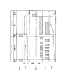
スチーム工程では、制御回路42は、給水弁40を所定時間(例えば5秒間)だけ開放動作させるようになっている。一方、洗浄工程及び各すすぎ工程では、制御回路42は水位センサ46からの入力信号に基づき洗浄槽2内の水位が「洗浄水位」に達したことを検知するまで給水弁40を開放動作させるようになっている。スチーム工程の蒸気生成動作が終了すると、制御回路42は排水動作を実行することなく洗浄工程に移行する。従って、洗浄工程の給水動作では、「洗浄水位」(図6中Aで示す水位)と「蒸気生成水位」(図6中Bで示す水位)との差に相当する水を洗浄槽2内に追加するだけで良く、スチーム工程で洗浄槽2内に貯留された水を洗浄工程で利用することができる。
In the steam process, the
また、洗浄工程及び加熱すすぎ工程では、制御回路42は扉開放検知センサ45からの入力信号に基づき洗浄槽2内の洗浄水の温度が所定温度となるように前記シーズヒータ25を間欠的に発熱させる。乾燥工程では、シーズヒータ25を間欠的に発熱させつつ送風機29を動作させることにより洗浄槽2内に温風を流通させる。
次に、スチーム工程について図6を参照しながら説明する。図6はスチーム工程及び洗浄工程時における給水弁40、ポンプ28、ヒータ25の動作タイミングを水位及び水温の変化と共に示している。
Further, in the cleaning process and the heating rinsing process, the
Next, the steam process will be described with reference to FIG. FIG. 6 shows the operation timings of the
図6に示すように、スチーム工程では、まず初めに制御回路42は給水弁40を開放して給水動作を実行する。この給水動作により蒸気生成水位まで洗浄槽2内に貯水される。
続いて、制御回路42はヒータ25及びポンプ28を交互に6回ずつ動作させることにより蒸気生成動作を実行する。この場合、1回目及び6回目のヒータ25の通電時間は12秒に設定されており、2〜5回目のヒータ25の通電時間は7秒に設定されている。これに対して、ポンプ28の動作時間は毎回12秒に設定されている。具体的には、制御回路42は、稼働時間のデューティ比が例えば1秒ON/2秒OFFとなるようにポンプモータ30を12秒間、一方向(正転方向)に低速で回転させる。
As shown in FIG. 6, in the steam process, first, the
Subsequently, the
この結果、ポンプ28は洗浄用ポンプとして機能し、洗浄槽2内の水がポンプ28によって汲み上げられ、噴射ノズル20,22の噴射孔20b,22bから洗浄槽2内に噴き出される。この場合、噴射孔22bから噴き出される水の勢いが弱く、噴射ノズル22がゆっくり回転するようにポンプモータ30の回転速度は、洗浄工程時におけるポンプモータ30の回転速度よりも低く設定されている。従って、噴射孔22bが保護カバー26の上方付近に位置するときに当該噴射孔22bから噴き出された水は遠くまで飛散することなく、保護カバー26を通してヒータ25の上に滴下される。このとき、ヒータ25の上面25aは略水平面となっているため、ヒータ25上に滴下された水はヒータ25上に保持され易い。このため、より多くの水をヒータ25に接触させることができる。
As a result, the
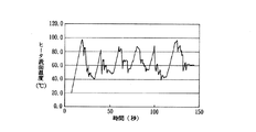
図7は、蒸気生成動作時のヒータ25の表面温度の変化を示している。図7に示すように、1回目の通電によりヒータ25の表面温度は100℃付近まで上昇する。従って、次にポンプ28が動作されてヒータ25の上に水が滴下されると、その水は瞬時に蒸発して洗浄槽2内を浮遊する。この結果、食器に付着している汚れは水を含み膨潤する。また、ヒータ25は水が滴下されることにより表面温度は40℃付近まで低下するが、再び通電されることにより100℃付近に戻る。従って、ポンプ動作時のヒータ25の表面温度は100℃付近となり、このようなヒータ25の上に水が滴下されることにより、効率良く蒸気が生成される。
FIG. 7 shows a change in the surface temperature of the
尚、ヒータ25の上に滴下された水の一部は蒸発せずに洗浄槽2内に戻される。従って、スチーム工程の経過と共に洗浄槽2内の水は温度上昇する。
このように本実施例によれば、洗浄工程の前にスチーム工程を設け、食器に付着した汚れを膨潤させた。このため、洗浄工程で噴射ノズル20,22から噴射された水によって食器に付着した汚れを効率良く、且つ、確実に洗い落とすことができる。特に、本実施例では、シーズヒータ25は、スチーム工程における蒸気生成用熱源と洗浄工程及び加熱すすぎ工程における水加熱用熱源として機能する。このため、両熱源を別のヒータから構成する場合に比べて部品点数の削減を図ることができる。
A part of the water dropped on the
Thus, according to the present Example, the steam process was provided before the washing | cleaning process, and the dirt adhering to tableware was swollen. For this reason, the stain | pollution | contamination adhering to tableware with the water sprayed from the
スチーム工程では、ヒータ25を間欠的に通電した。そして、スチーム工程開始時はヒータ25の表面温度が低いため、1回目のヒータ通電時間を2回目以降のヒータ通電時間よりも長くして、通電終了時にはヒータ25の表面温度が約100℃となるようにした。従って、ヒータ25に水を接触させると瞬時に蒸気を生成させることができる。このため、水を加熱して蒸気を発生させるときにヒータを水没させていた従来構成に比べて、蒸気を発生させるために必要な水の加熱時間を短く、且つ、熱エネルギーを少なくすることができる。
In the steam process, the
また、ヒータ25に水を接触させながらヒータ25に通電しても、ヒータ25の表面温度は余り上昇しない。しかも、ヒータ25の熱エネルギーは、ヒータ25と接触し蒸発することなく洗浄槽2内に戻される水の加熱に寄与するだけである。これに対して、本実施例ではヒータ25に水を接触させるときはヒータ25を停止させた。従って、水を蒸発させるためにヒータ25の熱エネルギーを有効に利用することができる。
Even if the
更に、ヒータ25を間欠的に通電したことにより、万一、洗浄槽2内に水が貯留されていない状態でスチーム工程が実行された場合のヒータ25の表面温度を低く抑えることができる。具体的には、洗浄槽2内に水が貯留されていない状態で、ヒータ25を上述のスチーム工程におけるタイミングで間欠通電したとき及び連続通電したときのヒータ25の表面温度の変化を図8及び図9に示す。
図8及び図9に示すように、洗浄槽2内に水が貯留されない状態でヒータ25を間欠的に通電したときの最終的なヒータ25の表面温度は約350℃であるのに対して、連続的に通電したときの最終的なヒータ25の表面温度は約600℃になる。
Furthermore, by energizing the
As shown in FIGS. 8 and 9, the final surface temperature of the
図10は本発明の第2の実施例を示すものであり、第1の実施例と異なるところを説明する。尚、第1の実施例と同一部分には同一符号を付している。第2の実施例は、スチーム工程における蒸気生成動作が第1の実施例と異なっている。具体的には、図10に示すように、スチーム工程が開始されると、制御回路42は、給水弁40を所定時間開放して洗浄槽2内に給水する。本実施例の蒸気生成水位は、ヒータ25が水没する水位をやや上回る水位に設定されている。従って、ここでは、制御回路42は第1の実施例における給水弁40の開放時間(5秒)よりも長い時間(例えば8秒)、給水弁40を開放する。
FIG. 10 shows a second embodiment of the present invention, and different points from the first embodiment will be described. The same parts as those in the first embodiment are denoted by the same reference numerals. The second embodiment is different from the first embodiment in the steam generation operation in the steam process. Specifically, as shown in FIG. 10, when the steam process is started, the
給水動作が終了すると、続いて、制御回路42はヒータ25を連続的に通電すると共にポンプ28を間欠的に4回動作させることにより蒸気生成動作を実行する。各回のポンプ28の動作時間は例えば12秒に、前記ポンプ28の停止時間は例えば8秒に設定されている。また、ポンプモータ30は、噴射ノズル20,22から水が殆ど噴射しない程度の低速で連続的に正転される。つまり、本実施例では、第1の実施例よりも蒸気生成動作時のポンプモータ30の回転速度が低く設定されている。
When the water supply operation is completed, subsequently, the
従って、ポンプ28の動作時は、洗浄槽2内の水はポンプ28によって汲み上げられるもののポンプ28内にとどまる。この結果、洗浄槽2内の水位が低下し、ヒータ25に水から露出する。このため、ヒータ25の表面温度が上昇し、ポンプモータの1回の動作が終了するころには約100℃付近になる。
ポンプモータ30の動作時間(12秒)が経過すると、ポンプモータ30は停止される。すると、ポンプ28内の水は逆流して洗浄槽2内に戻り、洗浄槽2内の水位が上昇する。この結果、ヒータ25が水没し、ヒータ25と水とが接触する。このとき、ヒータ25の表面温度は約100℃となっているため、ヒータ25と接触した水は急激に温度上昇し、蒸気が生成される。一方、水と接触することにより、ヒータ25の表面温度急激に低下する。
Therefore, when the
When the operation time (12 seconds) of the
上記したポンプモータ30の回転、停止が4回繰り返された後、上記生成動作は終了し、次の洗浄工程に移行する。
このように本実施例では、ポンプモータ30の駆動を制御して洗浄槽2内の水位を上下動させることにより、ヒータ25と水が接触しない状態、接触する状態が交互に現れるように構成した。従って、常時、ヒータ25を水没させる構成に比べて、ヒータの熱エネルギーを蒸気生成のために有効に利用することができる。
After the rotation and stop of the
As described above, in this embodiment, by controlling the driving of the
図11は本発明の第3の実施例を示すものであり、第2の実施例と異なるところを説明する。この第3の実施例では、ポンプモータの回転速度を変化させることにより洗浄槽2内の水位を上下させ、ヒータと水が接触しない状態、接触する状態が交互に現れるように構成した点が、第2の実施例と異なっている。
即ち、制御回路42は、ヒータ25を連続的に通電すると共にポンプモータ30を低速及び高速で交互に4回、正転させることにより蒸気生成動作を実行する。ポンプモータ30の低速回転時には噴射ノズル20,22から水が殆ど噴射せず、前記ポンプモータ30の高速回転時には噴射ノズル22から僅かに水が噴射するように、低速回転数及び高速回転数は設定されている。
FIG. 11 shows a third embodiment of the present invention, and the differences from the second embodiment will be described. In the third embodiment, the water level in the
That is, the
従って、本実施例では、噴射ノズル22の噴射孔22bから噴射される水がヒータ25に滴下することにより、ヒータ25と水とが接触する。
このような第3の実施例においても、第1及び第2の実施例と同様の作用、効果が得られる。
Therefore, in this embodiment, the water injected from the
In the third embodiment, the same operation and effect as in the first and second embodiments can be obtained.
図12は本発明の第4の実施例を示すものであり、第1の実施例と異なるところを説明する。この第4の実施例では、洗浄槽2内の底部のうち給水口38から保護カバー27までの部分に、給水口38から流出する水を前記保護カバー27に向かって誘導するための斜面61(誘導経路に相当)を設けている。また、保護カバー27の下面のうちヒータ25の上部に位置する部分にはリブ62を設けている。更に、本実施例では、給水弁40として流量制御弁が用いられている。
FIG. 12 shows a fourth embodiment of the present invention, and differences from the first embodiment will be described. In the fourth embodiment, a slope 61 (for guiding water flowing out from the
そして、制御回路42は次のように給水弁40及びヒータ25の通電を制御することによりスチーム工程を実行する。即ち、スチーム工程が開始されると、制御回路42はヒータ25を通電する。そして、ヒータ25の通電時間が所定の設定時間、具体的には、ヒータの表面温度が約100℃となる時間に達すると、制御回路42は給水弁40を開放して給水動作を開始する。このとき、制御回路42は、給水口38から水が少しずつ流出するように給水弁40の開弁量を調整するように構成されている。
And the
この結果、給水口38から流出する水は傾斜61に沿って保護カバー27に至る。そして、保護カバー27の上に至った水は当該カバー27の孔27aを通過した後,リブ62を伝ってヒータ25の上面に滴下する。ヒータ25の上面に滴下された水は瞬時に蒸発して洗浄槽2内を浮遊する。
スチーム工程中、少量ずつ給水口38から流出させる給水動作は継続される。スチーム工程の終了時、洗浄槽内の水位はヒータが水没しない水位となっており、洗浄工程に移行した制御回路42は、洗浄槽2内の水位が洗浄水位に達するまで通常の給水動作を実行して洗浄槽2内の水を追加する。
As a result, the water flowing out from the
During the steam process, the water supply operation for causing the water to flow out from the
このような本実施例によれば、給水口38から流出する水をヒータ25まで誘導する手段(斜面61、リブ62)を洗浄槽2内に設けたので、ポンプ28を動作させなくてもヒータ25と水とを効率良く接触させることができる。
According to this embodiment, since the means (
尚、本発明は上記した実施例に限定されるものではなく、例えば次のような変形が可能である。
蒸気生成水位を検出する水位センサを設けてもよい。そして、スチーム工程では、制御回路は、前記水位センサの出力信号に基づき洗浄槽2内の水位が蒸気生成水位に達するまで給水弁を開放させるように構成しても良い。
シーズヒータの表面のうち少なくとも上面に微細な凹凸を設けたり、珪酸ナトリウムを用いて親水性にしたりすることによりシーズヒータに接触した水の保持力を向上させるようにしても良い。このような構成により、シーズヒータと接触する水の量を増加させることができ、ひいては蒸気生成量を増加させることができる。
The present invention is not limited to the above-described embodiments, and for example, the following modifications are possible.
You may provide the water level sensor which detects a steam production | generation water level. In the steam process, the control circuit may be configured to open the water supply valve until the water level in the
You may make it improve the holding | maintenance power of the water which contacted the sheathed heater by providing a fine unevenness | corrugation at least in the upper surface among the surfaces of a sheathed heater, or making it hydrophilic using sodium silicate. With such a configuration, the amount of water in contact with the sheathed heater can be increased, and consequently the amount of steam generated can be increased.
加熱要素はシーズヒータに限らず、絶縁性を有するヒータであれば良い。
蒸気生成用のヒータと、洗浄工程及び加熱すすぎ工程時における洗浄水加熱用のヒータとを別に設けても良い。この場合、蒸気生成用のヒータを、洗浄槽内の底部とは異なる部位であって、噴射ノズルから噴射される水が当たる部位に配置すると良い。
第2の実施例において、ポンプモータを停止させて洗浄槽内の水位を上昇させ、ヒータと水を接触させるときは、ヒータの通電を停止するようにしても良い。
The heating element is not limited to a sheathed heater, but may be any heater having an insulating property.
A heater for generating steam and a heater for heating cleaning water in the cleaning process and the heating rinse process may be provided separately. In this case, the heater for generating steam may be disposed at a site that is different from the bottom in the cleaning tank and that receives water sprayed from the spray nozzle.
In the second embodiment, when the pump motor is stopped to raise the water level in the cleaning tank and the heater and water are brought into contact with each other, the energization of the heater may be stopped.
制御回路42は、水温センサ45の検知結果に基づき洗浄槽内に給水されているか否かを判断するように構成しても良い。そして、洗浄槽内に給水されていないと判断したときには、スチーム工程を実行しないように構成しても良い。このような構成によれば、ヒータ25の温度が過度に上昇することを防止でき安全性が向上する。この場合は、水温センサ45及び制御回路42が給水検知手段として機能する。
The
制御回路42は、蒸気生成動作時にファンモータを駆動して送風機を動作させるように構成しても良い。このような構成により、発生した蒸気を洗浄槽2内の全体に分散させることができる。
The
図面中、1は食器洗浄機、2は洗浄槽、22は噴射ノズル(水誘導手段)、25はシーズヒータ(熱源)、28はポンプ(ポンプ手段、水誘導手段)、29は送風機、30はポンプモータ(ポンプ手段、水誘導手段)、36がファンモータ、38は給水口、40は給水弁(給水装置)、42は制御回路(蒸気生成手段、洗浄手段)、62は斜面(誘導経路)を示す。
In the drawings, 1 is a dishwasher, 2 is a washing tub, 22 is an injection nozzle (water induction means), 25 is a sheathed heater (heat source), 28 is a pump (pump means, water induction means), 29 is a blower, 30 is Pump motor (pump means, water guiding means), 36 is a fan motor, 38 is a water supply port, 40 is a water supply valve (water supply device), 42 is a control circuit (steam generating means, washing means), 62 is a slope (guidance path) Indicates.
Claims (13)
前記洗浄槽内に配置された熱源と、
前記洗浄槽内に給水する給水装置を有し前記給水装置によって前記洗浄槽内に供給される水を前記熱源に誘導して接触させる水誘導手段と、
前記熱源及び前記水誘導手段を制御することにより蒸気を生成させる蒸気生成手段とを備えた食器洗浄機。 A washing tank for storing tableware;
A heat source disposed in the cleaning tank;
A water guiding means having a water supply device for supplying water into the cleaning tank, and for inducing and contacting water supplied into the cleaning tank by the water supply device to the heat source;
A dishwasher comprising steam generating means for generating steam by controlling the heat source and the water guiding means.
水誘導手段は、前記ポンプ手段及び前記噴射ノズルから構成され、
蒸気生成手段は、前記噴射ノズルから噴射される水が熱源に接触するように前記ポンプ手段を制御するように構成されていることを特徴とする請求項1記載の食器洗浄機。 A cleaning unit comprising: a water supply device; a pump unit that pumps up water stored and stored in the cleaning tank by the water supply device; and a spray nozzle that blows water pumped up by the pump unit onto the tableware,
The water guiding means is composed of the pump means and the injection nozzle,
2. The dishwasher according to claim 1, wherein the steam generating means is configured to control the pump means so that water sprayed from the spray nozzle contacts a heat source.
洗浄手段は、ポンプ手段を駆動して噴射ノズルから噴射される水を食器に吹き付けるときは、前記洗浄槽内の水位が前記熱源よりも上方に位置するまで給水装置に給水させると共に前記熱源に通電して前記洗浄槽内の水を加熱するように構成されていることを特徴とする請求項3記載の食器洗浄機。 The heat source is located at the bottom of the washing tank,
When the cleaning means drives the pump means to spray the water sprayed from the spray nozzle onto the tableware, the cleaning means supplies water to the water supply device until the water level in the cleaning tank is located above the heat source and energizes the heat source. The dish washer according to claim 3, wherein the dish washer is configured to heat water in the washing tank.
蒸気生成手段は、前記洗浄槽内の水位が前記熱源よりも上方に位置するまで給水装置に給水させた後、前記ポンプ手段を制御して前記洗浄槽内の水位を前記熱源よりも下方に位置させる第1の動作と前記洗浄槽内の水位を前記熱源よりも上方に位置させる第2の動作を交互に繰り返すと共に、前記第1の動作時に前記熱源を通電するように構成されていることを特徴とする請求項1記載の食器洗浄機。 A heat source is disposed at the bottom of the cleaning tank, and includes a water supply device, pump means for pumping up water stored in the cleaning tank by the water supply device, and water pumped up by the pump means to the tableware. A cleaning means having a spray nozzle for spraying,
The steam generating means supplies water to the water supply device until the water level in the cleaning tank is located above the heat source, and then controls the pump means to position the water level in the cleaning tank below the heat source. The first operation to be performed and the second operation to position the water level in the cleaning tank above the heat source are alternately repeated, and the heat source is energized during the first operation. The dishwasher according to claim 1, wherein
蒸気生成手段による蒸気生成動作時に前記給水装置によって前記洗浄槽内に供給された水の水位は、前記洗浄手段による食器洗浄動作時に前記給水装置によって前記洗浄槽内に供給された水の水位よりも低く設定され、
洗浄手段は、蒸気生成手段が蒸気を生成する動作を実行した後、前記給水装置を駆動して前記洗浄槽内に水を追加させるように構成されていることを特徴とする請求項1記載の食器洗浄機。 A cleaning unit comprising: a water supply device; a pump unit that pumps up water stored and stored in the cleaning tank by the water supply device; and a spray nozzle that blows water pumped up by the pump unit onto the tableware,
The water level supplied into the washing tank by the water supply device during the steam generation operation by the steam generation means is higher than the water level supplied into the washing tank by the water supply device during the dish washing operation by the cleaning means. Set low,
The cleaning means is configured to drive the water supply device to add water to the cleaning tank after the steam generating means performs an operation of generating steam. Dishwasher.
水誘導手段は、前記給水口から流出する水を熱源まで誘導する誘導経路を備えて構成されていることを特徴とする請求項1記載の食器洗浄機。 Provided with a water supply port that is provided in the cleaning tank and allows water from the water supply device to flow into the cleaning tank,
2. The dishwasher according to claim 1, wherein the water guiding means includes a guiding path for guiding water flowing out from the water supply port to a heat source.
蒸気生成手段は、熱源及び水誘導手段を制御して蒸気を生成させるときに前記送風機を駆動するように構成されていることを特徴とする請求項1記載の食器洗浄機。 Equipped with a blower to circulate the air in the washing tank,
2. The dishwasher according to claim 1, wherein the steam generating means is configured to drive the blower when the heat source and the water guiding means are controlled to generate steam.
蒸気生成手段は、前記給水検知手段により前記洗浄槽内に給水されたことが検知されたときに熱源に通電することを特徴とする請求項1記載の食器洗浄機。
Provided with water supply detection means for detecting that water has been supplied into the washing tank,
2. The dishwasher according to claim 1, wherein the steam generating means energizes the heat source when it is detected by the water supply detecting means that water has been supplied into the washing tank.
Priority Applications (1)
| Application Number | Priority Date | Filing Date | Title |
|---|---|---|---|
| JP2004123088A JP2005304619A (en) | 2004-04-19 | 2004-04-19 | Dishwasher |
Applications Claiming Priority (1)
| Application Number | Priority Date | Filing Date | Title |
|---|---|---|---|
| JP2004123088A JP2005304619A (en) | 2004-04-19 | 2004-04-19 | Dishwasher |
Publications (2)
| Publication Number | Publication Date |
|---|---|
| JP2005304619A true JP2005304619A (en) | 2005-11-04 |
| JP2005304619A5 JP2005304619A5 (en) | 2006-11-02 |
Family
ID=35434070
Family Applications (1)
| Application Number | Title | Priority Date | Filing Date |
|---|---|---|---|
| JP2004123088A Pending JP2005304619A (en) | 2004-04-19 | 2004-04-19 | Dishwasher |
Country Status (1)
| Country | Link |
|---|---|
| JP (1) | JP2005304619A (en) |
Cited By (7)
| Publication number | Priority date | Publication date | Assignee | Title |
|---|---|---|---|---|
| JP2007130143A (en) * | 2005-11-09 | 2007-05-31 | Toshiba Corp | Dishwasher |
| JP2007319590A (en) * | 2006-06-05 | 2007-12-13 | Toshiba Corp | Dishwasher |
| WO2009068381A1 (en) * | 2007-11-26 | 2009-06-04 | BSH Bosch und Siemens Hausgeräte GmbH | Dish washing machine |
| JP2010227496A (en) * | 2009-03-30 | 2010-10-14 | Mitsubishi Electric Corp | Dishwasher |
| KR20130070275A (en) * | 2011-12-19 | 2013-06-27 | 엘지전자 주식회사 | Dishwasher and method of controlling the same |
| JP2013158650A (en) * | 2012-02-06 | 2013-08-19 | Lg Electronics Inc | Control method of cleaning apparatus |
| KR101306717B1 (en) * | 2007-03-31 | 2013-09-11 | 엘지전자 주식회사 | Dish washer and Method for controlling dish washer |
-
2004
- 2004-04-19 JP JP2004123088A patent/JP2005304619A/en active Pending
Cited By (15)
| Publication number | Priority date | Publication date | Assignee | Title |
|---|---|---|---|---|
| JP4542981B2 (en) * | 2005-11-09 | 2010-09-15 | 株式会社東芝 | Dishwasher |
| JP2007130143A (en) * | 2005-11-09 | 2007-05-31 | Toshiba Corp | Dishwasher |
| JP2007319590A (en) * | 2006-06-05 | 2007-12-13 | Toshiba Corp | Dishwasher |
| JP4709692B2 (en) * | 2006-06-05 | 2011-06-22 | 株式会社東芝 | Dishwasher |
| KR101306717B1 (en) * | 2007-03-31 | 2013-09-11 | 엘지전자 주식회사 | Dish washer and Method for controlling dish washer |
| WO2009068381A1 (en) * | 2007-11-26 | 2009-06-04 | BSH Bosch und Siemens Hausgeräte GmbH | Dish washing machine |
| JP2010227496A (en) * | 2009-03-30 | 2010-10-14 | Mitsubishi Electric Corp | Dishwasher |
| KR20130070275A (en) * | 2011-12-19 | 2013-06-27 | 엘지전자 주식회사 | Dishwasher and method of controlling the same |
| KR101871270B1 (en) * | 2011-12-19 | 2018-06-28 | 엘지전자 주식회사 | Dishwasher and method of controlling the same |
| JP2013158650A (en) * | 2012-02-06 | 2013-08-19 | Lg Electronics Inc | Control method of cleaning apparatus |
| US9085843B2 (en) | 2012-02-06 | 2015-07-21 | Lg Electronics Inc. | Control method of laundry machine |
| US9328449B2 (en) | 2012-02-06 | 2016-05-03 | Lg Electronics Inc. | Control method of laundry machine |
| US9328448B2 (en) | 2012-02-06 | 2016-05-03 | Lg Electronics Inc. | Laundry machine with drying duct comprising a nozzle |
| US9334601B2 (en) | 2012-02-06 | 2016-05-10 | Lg Electronics Inc. | Control method of laundry machine |
| US9644306B2 (en) | 2012-02-06 | 2017-05-09 | Lg Electronics Inc. | Control method of laundry machine |
Similar Documents
| Publication | Publication Date | Title |
|---|---|---|
| KR101306717B1 (en) | Dish washer and Method for controlling dish washer | |
| KR100776434B1 (en) | Dish washer | |
| KR20120022427A (en) | A control method of a dishwasher | |
| JP2006314667A (en) | Dishwasher | |
| KR101268714B1 (en) | Dish washer and Controlling method thereof | |
| JP2005304619A (en) | Dishwasher | |
| JP2006345928A (en) | Dishwasher | |
| KR102443320B1 (en) | Dish washer and controlling method thereof | |
| JP2001112686A (en) | Dishwasher | |
| KR20100086892A (en) | Method for dishwasher operating for door opening protecting | |
| JP4985612B2 (en) | dishwasher | |
| JP4769134B2 (en) | Dishwasher | |
| JP2005329068A (en) | Dish washer | |
| JP4129412B2 (en) | Dishwasher | |
| JP2005130924A (en) | Dishwasher | |
| JP7205759B2 (en) | Washing machine | |
| JP4152152B2 (en) | Cleaning device and dishwasher | |
| JP5835933B2 (en) | Dishwasher | |
| JP2018011711A (en) | washing machine | |
| JP5262807B2 (en) | dishwasher | |
| KR20100096300A (en) | Controlling method of dishwasher | |
| JP5085410B2 (en) | dishwasher | |
| JP4769133B2 (en) | Dishwasher | |
| JP5770529B2 (en) | Dishwasher | |
| JP6116537B2 (en) | Dishwasher |
Legal Events
| Date | Code | Title | Description |
|---|---|---|---|
| A521 | Written amendment |
Free format text: JAPANESE INTERMEDIATE CODE: A523 Effective date: 20060914 |
|
| A621 | Written request for application examination |
Free format text: JAPANESE INTERMEDIATE CODE: A621 Effective date: 20060914 |
|
| A977 | Report on retrieval |
Free format text: JAPANESE INTERMEDIATE CODE: A971007 Effective date: 20090210 |
|
| A131 | Notification of reasons for refusal |
Free format text: JAPANESE INTERMEDIATE CODE: A131 Effective date: 20090512 |
|
| A521 | Written amendment |
Free format text: JAPANESE INTERMEDIATE CODE: A523 Effective date: 20090713 |
|
| A02 | Decision of refusal |
Free format text: JAPANESE INTERMEDIATE CODE: A02 Effective date: 20100209 |