JP2005304540A - Self-running type vacuum cleaner equipped with monitoring camera - Google Patents
Self-running type vacuum cleaner equipped with monitoring camera Download PDFInfo
- Publication number
- JP2005304540A JP2005304540A JP2004121743A JP2004121743A JP2005304540A JP 2005304540 A JP2005304540 A JP 2005304540A JP 2004121743 A JP2004121743 A JP 2004121743A JP 2004121743 A JP2004121743 A JP 2004121743A JP 2005304540 A JP2005304540 A JP 2005304540A
- Authority
- JP
- Japan
- Prior art keywords
- human body
- main body
- self
- angle
- camera
- Prior art date
- Legal status (The legal status is an assumption and is not a legal conclusion. Google has not performed a legal analysis and makes no representation as to the accuracy of the status listed.)
- Withdrawn
Links
- 238000012544 monitoring process Methods 0.000 title description 13
- 238000000034 method Methods 0.000 claims abstract description 21
- 238000001514 detection method Methods 0.000 claims description 50
- 238000004140 cleaning Methods 0.000 claims description 29
- 238000003384 imaging method Methods 0.000 claims description 23
- 230000005540 biological transmission Effects 0.000 claims description 19
- 238000005286 illumination Methods 0.000 claims description 15
- 230000001133 acceleration Effects 0.000 description 12
- 238000004891 communication Methods 0.000 description 10
- 239000000758 substrate Substances 0.000 description 8
- 239000004973 liquid crystal related substance Substances 0.000 description 7
- 238000012545 processing Methods 0.000 description 7
- 238000010586 diagram Methods 0.000 description 6
- 239000000428 dust Substances 0.000 description 5
- 230000005856 abnormality Effects 0.000 description 4
- 230000000694 effects Effects 0.000 description 3
- 238000005259 measurement Methods 0.000 description 3
- 230000003287 optical effect Effects 0.000 description 3
- 241000272525 Anas platyrhynchos Species 0.000 description 1
- 238000005452 bending Methods 0.000 description 1
- 238000006243 chemical reaction Methods 0.000 description 1
- 230000007423 decrease Effects 0.000 description 1
- 230000003247 decreasing effect Effects 0.000 description 1
- 238000002474 experimental method Methods 0.000 description 1
- 230000006698 induction Effects 0.000 description 1
- 238000013507 mapping Methods 0.000 description 1
- 239000000463 material Substances 0.000 description 1
- 239000002184 metal Substances 0.000 description 1
- 230000005855 radiation Effects 0.000 description 1
- 238000005096 rolling process Methods 0.000 description 1
- 238000012546 transfer Methods 0.000 description 1
Images


Classifications
-
- G—PHYSICS
- G08—SIGNALLING
- G08B—SIGNALLING OR CALLING SYSTEMS; ORDER TELEGRAPHS; ALARM SYSTEMS
- G08B13/00—Burglar, theft or intruder alarms
- G08B13/18—Actuation by interference with heat, light, or radiation of shorter wavelength; Actuation by intruding sources of heat, light, or radiation of shorter wavelength
- G08B13/189—Actuation by interference with heat, light, or radiation of shorter wavelength; Actuation by intruding sources of heat, light, or radiation of shorter wavelength using passive radiation detection systems
- G08B13/194—Actuation by interference with heat, light, or radiation of shorter wavelength; Actuation by intruding sources of heat, light, or radiation of shorter wavelength using passive radiation detection systems using image scanning and comparing systems
- G08B13/196—Actuation by interference with heat, light, or radiation of shorter wavelength; Actuation by intruding sources of heat, light, or radiation of shorter wavelength using passive radiation detection systems using image scanning and comparing systems using television cameras
- G08B13/19695—Arrangements wherein non-video detectors start video recording or forwarding but do not generate an alarm themselves
-
- G—PHYSICS
- G05—CONTROLLING; REGULATING
- G05D—SYSTEMS FOR CONTROLLING OR REGULATING NON-ELECTRIC VARIABLES
- G05D1/00—Control of position, course or altitude of land, water, air, or space vehicles, e.g. automatic pilot
- G05D1/02—Control of position or course in two dimensions
- G05D1/021—Control of position or course in two dimensions specially adapted to land vehicles
- G05D1/0231—Control of position or course in two dimensions specially adapted to land vehicles using optical position detecting means
- G05D1/0246—Control of position or course in two dimensions specially adapted to land vehicles using optical position detecting means using a video camera in combination with image processing means
-
- H—ELECTRICITY
- H04—ELECTRIC COMMUNICATION TECHNIQUE
- H04N—PICTORIAL COMMUNICATION, e.g. TELEVISION
- H04N7/00—Television systems
- H04N7/18—Closed-circuit television [CCTV] systems, i.e. systems in which the video signal is not broadcast
- H04N7/181—Closed-circuit television [CCTV] systems, i.e. systems in which the video signal is not broadcast for receiving images from a plurality of remote sources
-
- A—HUMAN NECESSITIES
- A47—FURNITURE; DOMESTIC ARTICLES OR APPLIANCES; COFFEE MILLS; SPICE MILLS; SUCTION CLEANERS IN GENERAL
- A47L—DOMESTIC WASHING OR CLEANING; SUCTION CLEANERS IN GENERAL
- A47L2201/00—Robotic cleaning machines, i.e. with automatic control of the travelling movement or the cleaning operation
- A47L2201/04—Automatic control of the travelling movement; Automatic obstacle detection
Abstract
Description
本発明は、掃除機構を備えた本体と、操舵及び駆動が可能な駆動機構とを備えるとともに、監視カメラを備えた自走式掃除機に関するものである。 The present invention relates to a self-propelled cleaner having a main body having a cleaning mechanism and a drive mechanism capable of steering and driving, and having a surveillance camera.
従来、複数のビデオカメラを配置し、行動制御に利用する自走式のロボットが知られている。例えば、特許文献1。
上述した従来の自走式ロボットにおいては、同じビデオカメラで周囲を撮影し、それぞれ異なる処理速度の画像処理をして行動制御に利用している。従って、侵入者などの監視に利用しようとする場合、侵入者が撮影可能範囲に正確に入っていないと撮影しても無意味な結果に終わるという課題があった。 In the conventional self-propelled robot described above, the surroundings are photographed by the same video camera, and image processing at different processing speeds is performed for use in behavior control. Therefore, when trying to use it for monitoring an intruder or the like, there is a problem that even if the intruder is not within the photographing range, the result is meaningless even if the image is taken.
むろん、正確に侵入者の位置をとらえ、顔や全体が写るようにズームや角度調整を行うことも理論的には可能であるが、制御に時間を要すると侵入者は撮影可能範囲からでてしまうし、制御を高速化するために処理速度が高速なCPUなどを利用すれば高価となったり、電源の消耗が激しくなってしまう。さらに、ズームや角度調整に要する別途のアクチュエータは、高速化の問題と、消費電源の問題があった。これらはいずれも自走式の掃除機を前提とした場合に採用し得ない課題であった。 Of course, it is theoretically possible to accurately capture the position of the intruder and adjust the zoom and angle so that the face and the whole image can be seen, but if the control takes time, the intruder is out of the shooting range. In addition, if a CPU having a high processing speed is used to speed up the control, it becomes expensive and power consumption is severe. Furthermore, the separate actuator required for zooming and angle adjustment has a problem of speeding up and a problem of power consumption. All of these were issues that could not be adopted when a self-propelled vacuum cleaner was assumed.
本発明は、上記課題に鑑みてなされたもので、簡易な構成で確実に侵入者を撮影することが可能な監視カメラを備えた自走式掃除機を提供することを目的とする。 The present invention has been made in view of the above problems, and an object of the present invention is to provide a self-propelled cleaner provided with a monitoring camera capable of reliably photographing an intruder with a simple configuration.
本発明は、上記課題に鑑みてなされたもので、掃除機構を備えた本体と、操舵及び駆動が可能な駆動機構とを備える自走式掃除機であって、上記本体には、それぞれ視野角が異なるとともに、仰角を異ならせて配置された複数のカメラ素子と、本体の周囲における人体の有無を検知して検知方向を取得することが可能な人体センサと、上記人体センサの検知結果に基づいて検知された人体の方向に上記本体を対面させた後、上記複数のカメラ素子のそれぞれで撮影して撮像イメージを入力し、同撮像イメージを所定の方法で出力する制御手段とを有する構成としてある。 The present invention has been made in view of the above problems, and is a self-propelled cleaner provided with a main body provided with a cleaning mechanism and a drive mechanism capable of steering and driving. Based on a plurality of camera elements arranged with different elevation angles, a human body sensor capable of detecting the presence or absence of a human body around the body and obtaining a detection direction, and a detection result of the human body sensor And a control unit that inputs the captured image by each of the plurality of camera elements and outputs the captured image by a predetermined method. is there.
上記のように構成した本発明においては、それぞれ視野角が異なるとともに仰角を異ならせて配置された複数のカメラ素子を有しており、制御手段は、本体の周囲における人体の有無を検知する人体センサの検知結果に基づき、同検知された人体の方向に本体を対面させた後、上記複数のカメラ素子のそれぞれで撮影して撮像イメージを入力し、同撮像イメージを所定の方法で出力する。 The present invention configured as described above has a plurality of camera elements arranged with different viewing angles and different elevation angles, and the control means detects the presence or absence of a human body around the body. Based on the detection result of the sensor, the main body is faced in the direction of the detected human body, and then captured by each of the plurality of camera elements, a captured image is input, and the captured image is output by a predetermined method.
本自走式掃除機は、視野角が異なるとともにそれぞれ仰角を異ならせて配置した複数のカメラ素子を有しており、検知した人体に本体を対面させて撮影すれば、それぞれのカメラ素子が予め予定した視野角の範囲で人体の撮影を試みる。視野角が狭いカメラ素子は予め侵入者の顔が撮影範囲の中央にくるように仰角を設定してあるのであり、侵入者が予定したとおりの身長や姿勢を取れば、撮影された撮像イメージの中央に侵入者の顔が写るはずである。ただし、侵入者の動きが素早かったり予定した姿勢でないとそのような狭い視野角の撮影範囲内に顔が写らないこともある。しかし、視野角が広い方のカメラ素子でも同時に撮影させており、狭い方の視野角から外れた場合であっても侵入者の姿は広い方の視野角のカメラ素子により確実に撮影可能となる。 This self-propelled cleaner has a plurality of camera elements that are arranged with different viewing angles and different elevation angles. Attempt to shoot the human body within the range of the scheduled viewing angle. The camera element with a narrow viewing angle is set in advance so that the intruder's face is in the center of the shooting range, and if the height and posture are as expected by the intruder, The face of the intruder should appear in the center. However, if the intruder moves quickly or is not in a planned posture, the face may not be captured within such a narrow viewing angle shooting range. However, even the camera element with the wider viewing angle is photographed at the same time, and even when the viewing angle deviates from the narrower viewing angle, the intruder can be reliably photographed with the camera element with the wider viewing angle. .
このように、カメラ素子ごとにズームやアクチュエータは必要とならないし、視野角の異なる複数のカメラ素子で撮影するので侵入者の姿を撮影し損なうことは極めて少なく、撮影範囲の調整に伴う余分な時間や電力を必要としないという効果がある。
視野角の設定はカメラ素子の性能であったり、人体センサの検知範囲であったり、本体の走行性能などによって適宜変更させる必要があるが、その一例として、請求項3にかかる発明では、複数のカメラ素子は、視野角が標準のものと、視野角が広角のものとを有しており、標準の視野角のカメラ素子を、広角の視野角のカメラ素子の仰角よりも低めとし、広角の視野角のカメラ素子は床面を一部に含める仰角とした構成としてある。
In this way, zooming and actuators are not required for each camera element, and since shooting is performed with a plurality of camera elements with different viewing angles, it is extremely unlikely that the intruder's figure will be missed. There is an effect that time and electric power are not required.
The setting of the viewing angle needs to be changed as appropriate depending on the performance of the camera element, the detection range of the human body sensor, the running performance of the main body, and the like. The camera element has a standard viewing angle and a wide viewing angle, and the standard viewing angle camera element is lower than the elevation angle of the wide viewing angle camera element. The viewing angle camera element is configured to have an elevation angle that includes the floor surface as a part.
このように構成した場合、広角の視野角のカメラ素子は床面を一部に含める仰角となっているので侵入者の足下から全体像を含める撮影が可能となり、標準の視野角のカメラ素子については視野角が狭い分だけ仰角は広角のものよりもやや低めとし、その撮影範囲内に侵入者の顔が入るようにして撮影を行うことができる。 When configured in this way, the camera element with a wide viewing angle has an elevation angle that includes the floor surface in part, so it is possible to shoot including the entire image from the feet of the intruder. Since the elevation angle is slightly lower than that of the wide angle by the narrow viewing angle, the intruder's face can be photographed within the photographing range.
人体を検知するセンサは各種のものを採用可能であり、その一例として、請求項4にかかる発明では、上記人体センサは、赤外線の受光光量の変化に基づいて赤外線発光動体を検知するものであり、上記本体の側面に複数備えた構成としてある。
このように構成した場合、人体の皮膚などからは赤外線を放射しているため、侵入者が侵入してきたときには、その移動に伴って赤外線の放射が変化し、上記人体センサにおける赤外線の受光光量が変化する。このため、人体センサは赤外線発光動体たる人体を検知できることになる。
Various sensors can be used to detect a human body. As an example, in the invention according to claim 4, the human body sensor detects an infrared light emitting moving body based on a change in the amount of received infrared light. The configuration includes a plurality of side surfaces of the main body.
In such a configuration, since infrared rays are radiated from the human skin or the like, when an intruder enters, the infrared radiation changes with the movement, and the amount of infrared light received by the human body sensor is increased. Change. For this reason, the human body sensor can detect a human body which is an infrared light emitting moving body.
また、この人体センサの検知結果を有効に利用するため、請求項5にかかる発明では、上記制御手段が複数の人体センサの検知状況に基づいて上記本体に対する相対角度を検出し、同相対角度をなくすように上記本体の回転角度を変化させ、上記カメラ素子にて撮影を行わせる構成としてある。 In order to effectively use the detection result of the human body sensor, in the invention according to claim 5, the control means detects a relative angle with respect to the main body based on detection states of a plurality of human body sensors, and the relative angle is obtained. The configuration is such that the rotation angle of the main body is changed so as to eliminate, and the camera element is used for photographing.
赤外線発光動体を検知する人体センサの場合、必ずしもその位置まで正確に検知できないことがあるが、複数の人体センサがある場合は、それぞれの人体センサの検知状況に基づいて上記本体に対する相対角度を検出することができる。例えば、隣接する二つの人体センサが同じ強度の検知結果を出力したならば、二つの人体センサの中間に侵入者がいるものと判断できる。また、等間隔の三つの人体センサが人体を検出し、中央の人体センサが最も強い検知結果を出力し、両隣の人体センサがそれよりも弱いが同じ強度の検知結果を出力していたとすれば、中央の人体センサの対面方向に侵入者がいるものと判断できる。 In the case of a human body sensor that detects infrared light emitting moving bodies, it may not always be possible to accurately detect that position, but when there are multiple human body sensors, the relative angle to the main body is detected based on the detection status of each human body sensor. can do. For example, if two adjacent human body sensors output detection results having the same intensity, it can be determined that an intruder is present between the two human body sensors. Also, if three equally spaced human sensors detect a human body, the central human sensor outputs the strongest detection result, and the adjacent human sensor outputs a detection result of the same strength but weaker than that. It can be determined that there is an intruder in the facing direction of the central human body sensor.
撮像イメージを出力する方法は様々であるが、その一例として、請求項6にかかる発明では、上記制御手段は、上記カメラ素子にて撮影した撮像イメージデータを無線で外部に出力する無線送信手段を有する構成としてある。
このように構成した場合、撮像イメージデータは本体から離れた外部機器に送られるため、たとえ侵入者が本体を破壊しようと試みたとしても撮像イメージデータは既に無線で出力されているので、同撮像イメージデータは無事であり、確実に侵入者の姿を警察などに通知するということが可能となる。
There are various methods for outputting a captured image. As an example, in the invention according to claim 6, the control means includes wireless transmission means for wirelessly outputting captured image data captured by the camera element to the outside. It is as composition to have.
In such a configuration, since the captured image data is sent to an external device that is remote from the main body, even if an intruder attempts to destroy the main body, the captured image data has already been output wirelessly. The image data is safe and it is possible to reliably notify the police of the intruder.
無線で出力する場合、各種の規格が存在するが、構成を簡易にするために一例として、請求項7にかかる発明では、上記無線送信手段は、無線LANモジュールであり、上記制御手段は、所定のプロトコルに従って上記複数のカメラ素子にて撮影した撮像イメージデータをそれぞれ出力する構成としてある。 For wireless output, various standards exist, but as an example for simplifying the configuration, in the invention according to claim 7, the wireless transmission means is a wireless LAN module, and the control means According to this protocol, the imaged image data taken by the plurality of camera elements is output.
このように構成した場合、有線LANが存在することを前提として、本体に備えられた無線LANモジュールを介して同有線LANに備えられたアクセスポイントに接続し、LANを介して所定の通信相手に撮像イメージデータを送信することができる。
有線LANへ接続し、さらにインターネットへ接続することも可能であるから、予め決めておいたユーザのもとへインターネットを介して同データを含む電子メールを送信するということも可能である。
ユーザは送られてきた撮像イメージデータを閲覧し、不審者であれば即座に警察に通報することができる。
一方、請求項8にかかる発明では、上記制御手段は、上記複数のカメラ素子にて撮影した撮像イメージデータを一旦記憶し、上記無線送信手段にて送信可能となってから送信する構成としてある。
上記のように構成した場合、複数のカメラ素子にて撮影した撮像イメージデータは一旦所定の領域に記憶される。侵入者を撮影しようとする場合、人体の検知から撮影までは迅速に行わなければならない。特に、処理速度が速くないCPUを利用する場合はなおさらである。これに対して無線送信手段が外部と送信するためには所定の時間を要することになる場合が多い。特に、節電のために無線送信手段の電源をオフにしているような場合にはなおさらである。また、LANのように所定のプロトコルを経ないと通信ができないような場合もある。このような通信開始のための手順を踏む間に侵入者が撮影可能範囲から出てしまうことのないように、撮影した撮像イメージデータを一旦所定の領域に記憶し、無線送信手段にて送信可能となってから送信する。
In such a configuration, on the assumption that a wired LAN exists, the wireless LAN module provided in the main body is connected to an access point provided in the wired LAN, and a predetermined communication partner is established via the LAN. Captured image data can be transmitted.
Since it is possible to connect to a wired LAN and further to the Internet, it is also possible to send an e-mail including the same data to a predetermined user via the Internet.
The user can browse the captured image data sent to the police and immediately notify the police if the person is a suspicious person.
On the other hand, in the invention according to claim 8, the control means is configured to temporarily store picked-up image data photographed by the plurality of camera elements and transmit the image data after it can be transmitted by the wireless transmission means.
When configured as described above, captured image data captured by a plurality of camera elements is temporarily stored in a predetermined area. When an intruder is to be photographed, the process from detection of the human body to photographing must be performed quickly. This is especially true when using a CPU whose processing speed is not fast. On the other hand, a predetermined time is often required for the wireless transmission means to transmit to the outside. This is especially true when the power of the wireless transmission means is turned off to save power. In some cases, communication is not possible unless a predetermined protocol is used, such as a LAN. The captured image data can be temporarily stored in a predetermined area and transmitted by wireless transmission means so that an intruder does not leave the shootable range while following the procedure for starting communication. Send after becoming.
この結果、一瞬の撮影チャンスを逃さず、確実に侵入者の姿を撮影をすることが可能となる。
また、請求項9にかかる発明では、上記制御手段は、上記人体センサにて人体を検知している間は上記複数のカメラ素子にて撮影を続け、所定枚数の撮影後、または、上記人体センサにて人体を検知できなくなってから上記無線送信手段にて送信する構成としてある。
As a result, an intruder can be reliably photographed without missing a momentary photographing opportunity.
Further, in the invention according to claim 9, the control means continues photographing with the plurality of camera elements while detecting the human body with the human body sensor, and after photographing a predetermined number of times or with the human body sensor. Then, the wireless transmission means transmits the signal after the human body cannot be detected.
上記のように構成した場合、人体センサにて人体を検知している間は上記複数のカメラ素子にて撮影を続ける。人体センサにて人体を検知している間は撮影を優先することにより、できるだけ多くの侵入者の姿を撮影して一回の撮影で撮影ミスが生じたとしても、次の回には撮影を成功させるようにし、できるだけ多くの姿をとらえることができるようになる。 When configured as described above, while the human body is detected by the human body sensor, photographing is continued with the plurality of camera elements. Priority is given to shooting while the human body is detected by the human body sensor, so that even if a shooting mistake occurs in one shot, the next shot will be taken. Try to be successful and be able to capture as many figures as possible.
そして、記憶領域の制限に基づく枚数の撮影後、または、人体センサにて人体を検知できなくなってから無線送信手段にて送信する。すなわち、無線送信に要する処理を後回しにすることでできるだけ多くの撮像イメージを得ることができるようになる。
以上のように視野角や仰角が異なる複数のカメラ素子を有するとしても、撮像範囲が暗ければ撮影できないということになりかねない。このため、請求項10にかかる発明では、上記複数のカメラ素子の撮影範囲に対面するように照明素子を有し、上記制御手段は、検知された人体の方向に上記本体を対面させるとともに同照明素子にて撮影範囲を照明させる構成としてある。
Then, after the number of images is taken based on the limitation of the storage area, or after the human body can no longer be detected by the human body sensor, it is transmitted by the wireless transmission means. That is, as many captured images as possible can be obtained by postponing the processing required for wireless transmission.
As described above, even if a plurality of camera elements having different viewing angles and elevation angles are included, it may be impossible to photograph if the imaging range is dark. For this reason, in the
このようにすれば、検知された人体の方向に本体を対面させるとともに照明素子にて撮影範囲を照明させるので、カメラ素子は照度不足で撮影できないといったミスを防止できる。
本体に備えられる掃除機構については、吸引タイプによる掃除機構を採用しても良いし、ブラシにより掻き込むタイプの掃除機構を採用しても良いし、両者を組み合わせて採用しても良い。また、操舵及び駆動が可能な駆動機構についても、各種の構成が可能である。駆動機構は、車輪のみならず、無端ベルトを駆動する構成で実現しても良い。むろん、これ以外にも、4輪、6輪など、各種の構成で駆動機構を実現可能である。
In this way, since the main body faces the direction of the detected human body and the photographing range is illuminated by the illumination element, it is possible to prevent a mistake that the camera element cannot shoot due to insufficient illuminance.
As for the cleaning mechanism provided in the main body, a suction type cleaning mechanism may be adopted, a cleaning mechanism of a type scraped with a brush may be adopted, or a combination of both may be adopted. Also, various configurations are possible for the drive mechanism capable of steering and driving. The drive mechanism may be realized by a configuration that drives not only the wheel but also an endless belt. Of course, besides this, the drive mechanism can be realized with various configurations such as four wheels and six wheels.
そして、以上のような構成を踏まえたより具体的な構成の一例として、請求項1にかかる発明は、掃除機構を備えた本体と、同本体における左右に配置されて個別に回転を制御可能で操舵と駆動を実現する駆動輪を有する駆動機構とを備える自走式掃除機であって、上記本体には、標準の視野角の標準カメラ素子と広角の視野角の広角カメラ素子であって、同広角カメラ素子は視野角内に床面が入る仰角で固定され、同標準カメラ素子は同仰角よりも低めに固定されたカメラ素子と、側面に複数備えられて赤外線の受光光量の変化に基づいて赤外線発光動体を検知する人体センサと、この複数の人体センサの検知状況に基づいて上記本体に対する相対角度を検出し、同相対角度をなくすように上記本体の回転角度を変化させ、上記カメラ素子にて撮影を行わせ、無線LANモジュールにより所定のプロトコルに従って同撮影した撮像イメージデータを無線で外部に出力する制御手段とを具備する構成としてある。 As an example of a more specific configuration based on the configuration described above, the invention according to claim 1 is a steering system that is disposed on the left and right sides of the main body having a cleaning mechanism and can be individually controlled in rotation. And a drive mechanism having a drive wheel that realizes driving, wherein the main body includes a standard camera element having a standard viewing angle and a wide angle camera element having a wide viewing angle. The wide-angle camera element is fixed at an elevation angle where the floor surface falls within the viewing angle. A human body sensor for detecting an infrared light emitting moving body, a relative angle to the main body based on detection states of the plurality of human body sensors, a rotation angle of the main body being changed so as to eliminate the relative angle, and the camera element To perform the photographing Te, is a structure in which and a control means for outputting to the outside the image pickup image data the captured wirelessly in accordance with a predetermined protocol by the wireless LAN module.
上記のような構成とすることにより、本体に対してそれぞれ所定の仰角で標準の視野角の標準カメラ素子と広角の視野角の広角カメラ素子が取り付けられており、かつ、それぞれの仰角については同広角カメラ素子において視野角内に床面が入る仰角で固定され、同標準カメラ素子は同仰角よりも低めに固定されており、側面に複数備えられた人体センサが赤外線の受光光量の変化に基づいて赤外線発光動体を検知すると、制御手段は同人体センサの検知状況に基づいて上記本体に対する相対角度を検出し、同相対角度をなくすように上記本体の回転角度を変化させ、上記カメラ素子にて撮影を行わせ、無線LANモジュールにより所定のプロトコルに従って同撮影した撮像イメージデータを無線で外部に出力する。 With the above-described configuration, a standard camera element with a standard viewing angle and a wide-angle camera element with a wide viewing angle are attached to the main body at a predetermined elevation angle, and the elevation angle of each camera is the same. Wide angle camera element is fixed at an elevation angle that allows the floor to enter the viewing angle, the standard camera element is fixed at a lower angle than the elevation angle, and multiple human body sensors on the side are based on changes in the amount of received infrared light. When the infrared light emitting moving object is detected, the control means detects the relative angle with respect to the main body based on the detection status of the human body sensor, changes the rotation angle of the main body so as to eliminate the relative angle, and uses the camera element. Photographing is performed, and the captured image data captured by the wireless LAN module according to a predetermined protocol is wirelessly output to the outside.
このようにして単に本体を人体に対面させる駆動を実現するだけで侵入者の顔と全体とを簡易な構成で確実に撮影することが可能となるという効果がある。 Thus, there is an effect that the face of the intruder and the entire face can be reliably photographed with a simple configuration simply by realizing the drive for causing the main body to face the human body.
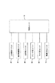
図1は、本発明にかかる自走式掃除機の概略構成をブロック図により示している。
同図に示すように、各ユニットを制御する制御ユニット10と、周囲に人間がいるか否かを検知する人体感知ユニット20と、周囲の障害物を検知するための障害物監視ユニット30と、移動を実現する走行系ユニット40と、掃除を行うためのクリーナ系ユニット50と、所定範囲を撮影するカメラ系ユニット60と、無線でLANに接続するための無線LANユニット70とから構成されている。なお、本体BDは薄型の略円筒形状をなしている。
FIG. 1 is a block diagram showing a schematic configuration of a self-propelled cleaner according to the present invention.
As shown in the figure, a
図2は、各ユニットを具体的に実現する電気系の構成をブロック図により示している。
制御ユニット10として、CPU11と、ROM13と、RAM12がバス14を介して接続されている。CPU11は、ROM13に記録されている制御用プログラムおよび各種パラメータテーブルに従い、RAM12をワークエリアとして使用して各種の制御を実行する。上記制御用プログラムの内容については後述する。
FIG. 2 is a block diagram showing the configuration of an electric system that specifically realizes each unit.
As the
また、バス14には操作パネルユニット15が備えられ、同操作パネルユニット15には、各種の操作用スイッチ15aと、液晶表示パネル15bと、表示用LED15cが備えられている。液晶表示パネルは多階調表示が可能なモノクロ液晶パネルを使用しているが、カラー液晶パネルなどを使用することも可能である。
The
本自走式掃除機はバッテリー17を有しており、CPU11はバッテリ監視回路16を介してバッテリー17の残量をモニター可能となっている。なお、同バッテリー17は誘導コイル18aを介して非接触で供給される電力を用いて充電する充電回路18を備えている。バッテリー監視回路16は主にバッテリー17の電圧を監視して残量を検知する。
This self-propelled cleaner has a
人体感知ユニット20として、四つの人体センサ21(21fr,21rr,21fl,21rl)が前方左右斜め方向と後方左右斜め方向に対面させて備えられている。各人体センサ21は赤外線の受光センサを備えるとともに受光した赤外線の光量の変化に基づいて人体の有無を検知するものであり、変化する赤外線照射物体を検知したとき出力用のステータスを変化させるため、CPU11は上記バス14を介して同人体センサ21の検知を取得することが可能となっている。すなわち、CPU11は所定時間毎に各人体センサ21fr,21rr,21fl,21rlのステータスを取得しにいき、取得したステータスが変化していれば、同人体センサ21fr,21rr,21fl,21rlの対向方向に人体の存在を検知することが可能となる。
As the human
ここでは赤外線の光量変化に基づくセンサによって人体センサを構成しているが、人体センサはこれに限られるものではない。例えば、CPUの処理量が上がればカラー画像を撮影し、人体に特徴的な肌色の領域を探し、同領域の大きさ、変化に基づいて人体を検知するという構成を実現することもできる。 Here, the human body sensor is configured by a sensor based on a change in the amount of infrared light, but the human body sensor is not limited to this. For example, if the processing amount of the CPU increases, a configuration can be realized in which a color image is taken, a skin color region characteristic of the human body is searched, and the human body is detected based on the size and change of the region.
障害物監視ユニット30は、オートフォーカス(以下、AFと呼ぶ。)用測距センサとしてのAF用パッシブセンサ31(31R,31FR,31FM,31FL,31L,31CL))とその通信用インターフェイスであるAFセンサ通信I/O32と、照明用LED33と、各LEDに駆動電流を供給するLEDドライバ34とから構成されている。まず、AF用パッシブセンサ31の構成について説明する。図3はAF用パッシブセンサ31の概略構成を示している。二軸のほぼ平行な光学系31a1,31a2と、同光学系31a1,31a2の結像位置にほぼそれぞれ配設されたCCDラインセンサ31b1,31b2と、各CCDラインセンサ31b1,31b2の撮像イメージデータを外部に出力するための出力I/O31cとを備えている。
The
CCDラインセンサ31b1,31b2は160〜170画素のCCDセンサを有しており、各画素ごとに光量を表す8ビットのデータを出力可能となっている。光学系が二軸であるので、結像イメージには距離に応じたずれが生じており、それぞれのCCDラインセンサ31b1,31b2が出力するデータのずれに基づいて距離を計測できる。例えば、近距離になるほど結像イメージのずれが大きく、遠距離になるほど結像イメージのずれはなくなっていく。従って、一方の出力データにおける4〜5画素毎のデータ列を画報の出力データ中でスキャンし、元のデータ列のアドレスと発見されたデータ列のアドレスとの相違を求め、相違量で予め用意しておいた相違量−距離変換テーブルを参照し、実際の距離を求めることになる。 The CCD line sensors 31b1 and 31b2 have a CCD sensor of 160 to 170 pixels, and can output 8-bit data representing the amount of light for each pixel. Since the optical system is biaxial, the imaged image has a shift corresponding to the distance, and the distance can be measured based on the shift of data output from the CCD line sensors 31b1 and 31b2. For example, the shift of the image is larger as the distance is shorter, and the shift of the image is eliminated as the distance is longer. Therefore, the data string for every 4 to 5 pixels in one output data is scanned in the output data of the image report, and the difference between the address of the original data string and the address of the discovered data string is obtained. The actual distance is obtained by referring to the prepared difference amount-distance conversion table.
AF用パッシブセンサ31R,31FR,31FM,31FL,31L,31CLのうち、AF用パッシブセンサ31FR,31FM,31FLは正面の障害を検知するために利用され、AF用パッシブセンサ31R,31Lは前方左右直前の障害を検知するために利用され、AF用パッシブセンサ31CLは前方天井までの距離を検知するために利用されている。
Of the AF
図4は正面と前方左右直前の障害をAF用パッシブセンサ31で検知する際の原理を示している。これらのAF用パッシブセンサ31は周囲の床面に対して斜めに向けて配置されている。対向方向に障害物が無い場合、AF用パッシブセンサ31による測距距離はほぼ全撮像範囲においてL1となる。しかし、図面で一点鎖線で示すように段差がある場合、その測距距離はL2となる。測距距離が伸びたら下がる段差があると判断できる。また、二点鎖線で示すように上がる段差があれば測距距離はL3となる。障害物があるときも上がる段差と同様に測距距離は同障害物までの距離として計測され、床面よりも短くなる。
FIG. 4 shows the principle for detecting an obstacle immediately before the front and left and right with the AF
本実施形態においては、AF用パッシブセンサ31を前方の床面に斜めに配向した場合、その撮像範囲は約10cmとなった。本自走式クリーナの幅が30cmであったので、三つのAF用パッシブセンサ31FR,31FM,31FLについては撮像範囲が重ならないように僅かに角度を変えて配置している。これにより、三つのAF用パッシブセンサ31FR,31FM,31FLにより前方方向の30cmの範囲での障害物と段差を検知できるようになっている。むろん、検知幅はセンサの仕様や取付位置などに応じて変化し、実際に必要となる幅に応じた数のセンサを利用すればよい。
In the present embodiment, when the AF
一方、前方左右直前の障害を検知するAF用パッシブセンサ31R,31Lについては撮像範囲を垂直方向を基準として床面に対して斜めに配置している。また、AF用パッシブセンサ31Rを本体左方に取り付けつつ本体中央を横切って右方直前位置から本体幅を超えた右方の範囲を撮像するように対向させてあり、AF用パッシブセンサ31Lを本体右方に取り付けつつ本体中央を横切って左方直前位置から本体幅を超えた左方の範囲を撮像するように対向させてある。
On the other hand, the AF
クロスさせないで左右の直前位置を撮影するようにすると、センサは急角度で床面に対面させなければならず、このようにすると撮像範囲が極めて狭くなってしまうので、複数のセンサが必要となる。このため、敢えてクロスさせる配置とし、撮像範囲を広げて少ない数のセンサで必要範囲をカバーできるようにしている。また、撮像範囲を垂直方向を基準として斜めに配置するのは、CCDラインセンサの並び方向が垂直方向に向くことを意味しており、図5に示すように撮像できる幅がW1となる。ここで、撮像範囲の右側で床面までの距離L4は短く、左側で距離L5が長くなっている。本体BDの側面の境界ラインが図面上の波線位置Bであると、境界ラインまでの撮像範囲は段差の検知などに利用され、境界ラインを超える撮像範囲は壁面の有無を検知するために利用される。 If the left and right positions are photographed without crossing, the sensor must face the floor surface at a steep angle, and in this case, the imaging range becomes extremely narrow, so a plurality of sensors are required. . For this reason, the arrangement is made to cross, and the imaging range is widened so that the required range can be covered with a small number of sensors. Further, arranging the imaging range obliquely with respect to the vertical direction means that the arrangement direction of the CCD line sensors is directed in the vertical direction, and the width capable of imaging is W1, as shown in FIG. Here, the distance L4 to the floor surface is short on the right side of the imaging range, and the distance L5 is long on the left side. If the boundary line on the side surface of the main body BD is a wavy position B on the drawing, the imaging range up to the boundary line is used for detecting a step, and the imaging range exceeding the boundary line is used for detecting the presence or absence of a wall surface. The
前方天井までの距離を検知するAF用パッシブセンサ31CLは天井に対面している。通常はAF用パッシブセンサ31CLが検知する床面から天井までの距離が一定であるが、壁面に近づいてくると撮像範囲が天井ではなく壁面となるので、測距距離が短くなってくる。従って、前方壁面の存在をより正確に検知できる
図6は各AF用パッシブセンサ31R,31FR,31FM,31FL,31L,31CLの本体BDへの取り付け位置を示すとともに、それぞれの床面での撮像範囲を括弧付きの符号で対応させて示している。なお、天井については撮像範囲は省略している。
The AF passive sensor 31CL that detects the distance to the front ceiling faces the ceiling. Normally, the distance from the floor surface to the ceiling detected by the AF passive sensor 31CL is constant, but when approaching the wall surface, the imaging range becomes the wall surface instead of the ceiling, and the distance measurement distance becomes shorter. Accordingly, the presence of the front wall surface can be detected more accurately. FIG. 6 shows the positions where the AF
AF用パッシブセンサ31R,31FR,31FM,31FL,31Lの撮像を証明するように白色LEDからなる右照明用LED33Rと、左照明用LED33Lと、前照明用LED33Mを備えており、LEDドライバ34はCPU11からの制御指示に基づいて駆動電流を供給して照明できるようになっている。これにより、夜間であったり、テーブルの下などの暗い場所でもAF用パッシブセンサ31から有効な撮像イメージのデータを得ることができるようになる。
In order to prove the imaging of the AF
走行系ユニット40は、モータドライバ41R,41Lと、駆動輪モータ42R,42Lと、この駆動輪モータ42R,42Lにて駆動される図示しないギアユニットと駆動輪を備えている。駆動輪は本体BDの左右に一輪ずつ配置されており、この他に駆動源を持たない自由転動輪が本体の前方側中央下面に取り付けられている。駆動輪モータ42R,42Lは回転方向と回転角度をモータドライバ41R,41Lによって詳細に駆動可能であり、各モータドライバ41R,41LはCPU11からの制御指示に応じて対応する駆動信号を出力する。また、駆動輪モータ42R,42Lと一体的に取り付けられているロータリーエンコーダの出力から現実の駆動輪の回転方向と回転角度が正確に検知できるようになっている。なお、ロータリーエンコーダは駆動輪と直結させず、駆動輪の近傍に自由回転可能な従動輪を取り付け、同従動輪の回転量をフィードバックさせることによって駆動輪にスリップが生じているような場合でも現実の回転量を検知できるようにしても良い。走行系ユニット40には、この他に地磁気センサ43が備えられており、地磁気に照らし合わせて走行方向を判断できるようになっている。また、加速度センサ44はXYZ三軸方向における加速度を検知し、検知結果を出力する。
The
ギアユニットや駆動輪は各種のものを採用可能であり、円形のゴム製タイヤを駆動させるようにしたり、無端ベルトを駆動させるようにして実現しても良い。
本自走式掃除機における掃除機構は、前方両サイドに配置されて本体BDの進行方向における両側寄りのゴミなどを当該本体BDにおける中央付近にかき寄せるサイドブラシと、本体の中央付近にかき寄せられたゴミをすくい上げるメインブラシと、同メインブラシによりすく上げられるゴミを吸引してダストボックス内に収容する吸引ファンとから構成されている。クリーナ系ユニット50は、各ブラシを駆動するサイドブラシモータ51R,51Lとメインブラシモータ52、それぞれのモータに駆動電力を供給するモータドライバ53R,53L,54と、吸引ファンを駆動する吸引モータ55と、同吸引モータに駆動電力を供給するモータドライバ56とから構成されている。サイドブラシやメインブラシを使用した掃除は床面の状況やバッテリーの状況やユーザの指示などに応じてCPU11が適宜判断して制御するようにしている。
Various types of gear units and drive wheels can be employed, and may be realized by driving a circular rubber tire or driving an endless belt.
The cleaning mechanism in the self-propelled cleaner is arranged on both front sides and scrapes dust near the both sides in the traveling direction of the main body BD to the vicinity of the center of the main body BD, and is scraped to the vicinity of the center of the main body BD. The main brush scoops up the dust and a suction fan that sucks up the dust scooped up by the main brush and stores it in the dust box. The
カメラ系ユニット60は、それぞれ視野角の異なる二つのCMOSカメラ61,62を備えており、本体BDの正面方向であってそれぞれことなる仰角にセットされている。また、各カメラ61,62への撮像を指示するとともに撮像イメージを出力するためのカメラ通信I/O63も備えられている。さらに、カメラ61,62の撮像方向に対面させて15コの白色LEDからなるカメラ用照明LED64と、同LEDに照明用駆動電力を供給するためのLEDドライバ65を備えている。
The
図10は、カメラ系ユニット60の外観を斜視図により示している。
カメラ系ユニット60はオプションとして取り付け可能となっており、本体BDには金属板材を屈曲加工した取り付けベース66が備えられている。上記CMOSカメラ61,62やカメラ用照明LED64などを載置した基板67が提供され、同取り付けベース66にネジ止め固定するようになっている。取り付けベース66は基部66aと、当該基部66aを水平方向から約45度傾斜させて保持するために上記基部66aの下方縁部の両側端から後方に延設された二つの脚部66bと、二つの脚部66bの間で基部66aに対してほぼ垂直に屈曲されて上記基板67の下方縁部を支持する支持用凸縁部66cと、基部66aの上方縁部の両端から上方に帯板状に延設されるとともに二回90度屈曲されることによって先端側を基部66aと平行に対面させ、かつ、雌ねじ穴を形成された固定片66dを備えている。
FIG. 10 is a perspective view showing the external appearance of the
The
図11に示すように、先に基板67の上端を上記固定片66dと基部66aとの間に入り込ませ、奥まで入った時点で下端を支持用凸縁部66cの上に載せるように押し込み、最後に雌ねじ穴66d1に雄ねじ66d2を螺合させて基板67がずれないように固定する。なお、基板67の上端両側部と、下端中央部には上記固定片66dと支持用凸縁部66cに合わせた切り込み67a,67bを形成してあり、正確な位置決めが可能となっている。
As shown in FIG. 11, the upper end of the
CMOSカメラ61は、視野角110度の広角(レンズ)カメラであり、基板67に対して撮影方向が垂直となるように固定されている。視野角が110度であり、基板67自体が45度傾斜した取り付けベース66に取り付けられるので、撮影範囲は水平面より下方に10度の範囲から110度の範囲となる。従って、この意味で撮影範囲の一部には床面を含むことになる。
The
CMOSカメラ62は、視野角58度の標準(レンズ)カメラであり、基板67に対して15度傾斜して取り付けるためのくさび形アダプタ62aを敷いて固定されている。視野角が58度であるから、撮影範囲は水平方向に対して1度〜57度の範囲であり、被写体から2m離れたところで撮影すると、0.034m〜3.078mの範囲となる。この場合は被写体を撮影できる可能性が高い。これに対して被写体が近接して1m離れたところで撮影すると、0.017m〜1.539mの範囲となり、姿勢によっては侵入者の顔が撮影されないこともある。
The
しかし、CMOSカメラ61の撮影範囲は水平面より下方に10度の範囲から110度の範囲であるから、撮影範囲としては十分カバーされているし、床面から1m+(カメラの高さ)の高さを中心として上方天井までが撮影されているので、侵入者の顔が撮影されている可能性は非常に高い。
However, since the shooting range of the
また、CMOSカメラ61,62は後述するように本体BDのポジショニング後、即座に同時に撮影されているので、カメラのポジショニングやフォーカシングの時間が不要であり、シャッターチャンスを逃さない。
無線LANユニット70は、無線LANモジュール71を有しており、CPU11は所定のプロトコルに従って外部LANと無線によって接続可能となっている。無線LANモジュール71は、図示しないアクセスポイントの存在を前提として、同アクセスポイントはルータなどを介して外部の広域ネットワーク(例えばインターネット)に接続可能な環境となっていることとする。従って、インターネットを介した通常のメールの送受信やWEBサイトの閲覧といったことが可能である。なお、無線LANモジュール71は、規格化されたカードスロットと、同スロットに接続される規格化された無線LANカードなどから構成されている。むろん、カードスロットは他の規格化されたカードを接続することも可能である。
Further, since the
The
次に、上記構成からなる自走式掃除機の動作について説明する。まず、清掃動作について説明する。
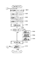
図7及び図8は上記CPU11が実行する制御プログラムに対応したフローチャートを示しており、図9は同制御プログラムに従って本自走式掃除機が走行する走行順路を示す図である。
電源オンにより、CPU11は図7の走行制御を開始する。ステップS110ではAF用パッシブセンサ31の検知結果を入力し、前方エリアを監視する。前方エリアの監視に使用するのはAF用パッシブセンサ31FR,31FM,31FLの検知結果であり、平坦な床面であれば、その撮像イメージから得られるのは図4に示す斜め下方の床面までの距離L1である。それぞれのAF用パッシブセンサ31FR,31FM,31FLの検知結果に基づき、本体BD幅に一致する前方の床面が平坦であるか否かが判断できる。ただし、この時点では、各AF用パッシブセンサ31FR,31FM,31FLが対面している床位置と本体の直前位置までの間の情報は何も得られていないので死角となる。
Next, the operation of the self-propelled cleaner having the above configuration will be described. First, the cleaning operation will be described.
7 and 8 are flowcharts corresponding to the control program executed by the
When the power is turned on, the
ステップS120ではモータドライバ41R,41Lを介して駆動輪モータ42R,42Lに対してそれぞれ回転方向を異にしつつ同回転量の駆動を指示する。これにより本体BDはその場で回転を始める。同じ場所での360度の回転(スピンターン)に要する駆動モータ42R,42Lの回転量は予め分かっており、CPU11は同回転量をモータドライバ41R,41Lに指示している。
In step S120, the
スピンターン中、CPU11はAF用パッシブセンサ31R,31Lの検知結果を入力し、本体BDの直前位置の状況を判断する。上述した死角はこの間の検知結果により、ほぼなくなり、段差、障害物が何も無い場合、周囲の平坦な床面の存在を検知できる。
ステップS130ではCPU11はモータドライバ41R,41Lを介して駆動輪モータ42R,42Lに対してそれぞれ同回転量の駆動を指示する。これにより本体BDは直進を開始する。直進中、CPU11はAF用パッシブセンサ31FR,31FM,31FLの検知結果を入力し、正面に障害物がいないか判断しながら前進する。そして、同検知結果から正面に障害物たる壁面が検知できたら、その壁面の所定距離だけ手前で停止する。
During the spin turn, the
In step S130, the
ステップS140では右に90度回転する。ステップS130で壁面の所定距離だけ手前で停止したが、この所定距離は本体BDが回転動作するときに同壁面に衝突せず、また、直前および左右の状況を判断するためのAF用パッシブセンサ31R,31Lが検知する本体幅の外側にあたる範囲の距離である。すなわち、ステップS130にてAF用パッシブセンサ31FR,31FM,31FLの検知結果に基づいて停止し、ステップS140にて90度回転するときには、少なくともAF用パッシブセンサ31Lが壁面の位置を検知できる程度の距離となるようにしている。また、90度回転するときには、上記AF用パッシブセンサ31R,31Lの検知結果に基づいて直前位置の状況を判断しておく。図9はこのようにしてたどり着いた平面図で見たときの部屋の左下角を清掃開始位置として清掃走行を開始する状況を示している。
In step S140, it is rotated 90 degrees to the right. In step S130, the actuator stops at a predetermined distance on the wall surface, but this predetermined distance does not collide with the wall surface when the main body BD rotates, and the AF
清掃走行開始位置へたどり着く方法はこれ以外にも各種の方法がある。壁面に当接する状況において右に90度回転するだけでは、最初の壁面の途中から始めることになることもあるため、図9に示すように左下角の最適位置にたどり着くのであれば、壁面に当接して左90度回転し、正面の壁面に当接するまで前進し、当接した時点で180度回転することも望ましい走行制御である。 There are various other methods for reaching the cleaning travel start position. If you rotate 90 degrees to the right while in contact with the wall surface, it may start from the middle of the first wall surface, so if you reach the optimal position in the lower left corner, as shown in FIG. It is also desirable travel control to rotate 90 degrees to the left, move forward until it contacts the front wall surface, and rotate 180 degrees when contacted.
ステップS150では、清掃走行を実施する。同清掃走行のより詳細なフローを図8に示している。前進走行するにあたり、ステップS210〜S240にて各種のセンサの検知結果を入力している。ステップS210では前方監視センサデータ入力しており、具体的にはAF用パッシブセンサ31FR,31FM,31FL,31CLの検知結果を入力し、走行範囲の前方に障害物あるいは壁面が存在しないか否かの判断に供することになる。なお、前方監視という場合には、広い意味での天井の監視も含めている。 In step S150, cleaning travel is performed. A more detailed flow of the cleaning traveling is shown in FIG. When traveling forward, detection results of various sensors are input in steps S210 to S240. In step S210, forward monitoring sensor data is input. Specifically, detection results of AF passive sensors 31FR, 31FM, 31FL, and 31CL are input, and whether or not an obstacle or a wall surface exists in front of the traveling range. It will be used for judgment. In addition, in the case of forward monitoring, monitoring of the ceiling in a broad sense is included.
ステップS220では段差センサデータ入力をしており、具体的にはAF用パッシブセンサ31R,31Lの検知結果を入力し、走行範囲の直前位置に段差がないか否かの判断に供することになる。また、壁面や障害物に沿って平行に移動するときには壁面や障害物までの距離を計測し、平行に移動しているか否かの判断に供することになる。
In step S220, step sensor data is input. Specifically, the detection results of the AF
ステップS230では地磁気センサデータ入力をしており、具体的には地磁気センサ43の検知結果を入力し、直進走行中に走行方向が変化していないか否かを判断するのに利用する。例えば、清掃走行開始時の地磁気の角度を記憶しておき、走行中に検出される角度が記憶されている角度と異なった場合には、左右の駆動輪モータ42R,42Lの回転量をわずかに異ならせて進行方向を修正し、元の角度へ戻す。例えば、地磁気の角度に基づいて角度が増加する方向へ変化(359度から0度への変化は例外点となる))したら左方向へ軌道を修正する必要があり、右の駆動輪モータ42Rの回転量を左の駆動輪モータ42Lの回転量よりも僅かに増やすようにそれぞれのモータドライバ41R,41Lへ駆動を制御する指示を出力する。
In step S230, geomagnetic sensor data is input. Specifically, the detection result of the
ステップS240では、加速度センサデータ入力をしており、具体的には加速度センサ44の検知結果を入力し、走行状態の確認に供することになる。例えば、直進走行開始時に概ね一定の方向への加速度を検知できれば正常な走行と判断できるが、回転する加速度を検知すれば片方の駆動輪モータが駆動されていないような異常を判断できる。また、正常な範囲の加速度値を超えたら段差などから落下したり、横転したような異常を判断できる。そして、前進中に後方にあたる方向への大きな加速度を検知したら前方の障害物に当接した異常を判断できる。このように、加速度値を入力して目標加速度を維持するとか、その積分値に基づいて速度を得るというような走行に対する直接的な制御をすることはないが、異常検出の目的として加速度値を有効に利用している。
In step S240, acceleration sensor data is input. Specifically, the detection result of the
ステップS250では、ステップS210とステップS220で入力したAF用パッシブセンサ31FR,31FM,31CL,31FL,31R,31Lの検知結果に基づいて障害物の判定を行う。障害物の判定は、正面、天井、直前のそれぞれの部位毎に行う。正面は障害物あるいは壁面の意味として判定し、直前は段差の判定とともに走行範囲外の左右の状況、例えば壁面の有無などを判定する。天井は鴨居などによって天井までの距離が下がってきているときに正面に障害物がないとしても、そこからは廊下であって室外に出てしまうことを判定するのに利用される。 In step S250, the obstacle is determined based on the detection results of the AF passive sensors 31FR, 31FM, 31CL, 31FL, 31R, and 31L input in steps S210 and S220. Obstacles are determined for each of the front, ceiling, and immediately preceding parts. The front is determined as the meaning of an obstacle or a wall, and immediately before the step is determined, the right and left conditions outside the traveling range, for example, the presence or absence of a wall are determined. Even if there is no obstacle in the front when the distance to the ceiling is decreasing due to a duck or the like, the ceiling is used to determine that it is a corridor and goes out of the room.
ステップS260では、各センサからの検知結果を総合的に判断し、回避の必要があるか否かを判断する。回避の必要がない限りステップS270の清掃処理を実行する。清掃処理は、サイドブラシとメインブラシを回転させつつ、ゴミを吸引する処理であり、具体的にはモータドライバ53R,53L,54,56に各モータ51R,51L,52,55を駆動させる指示を出力する。むろん、走行中は常に同指示を出しているのであり、後述するように清掃走行の終端条件が成立したときに停止させることになる。
In step S260, the detection result from each sensor is comprehensively determined to determine whether or not it is necessary to avoid it. Unless there is a need for avoidance, the cleaning process in step S270 is executed. The cleaning process is a process of sucking dust while rotating the side brush and the main brush. Specifically, the
一方、回避が必要と判断されると、ステップS280にて右に90度ターンを実施する。このターンは同じ位置での90度ターンであり、モータドライバ41R,41Lを介して駆動輪モータ42R,42Lに対してそれぞれ回転方向を異にしつつ90度ターンに必要なだけの回転量の駆動を指示する。回転方向は右の駆動輪に対して後退の方向であり、左の駆動輪に対して前進の方向となる。回転中は段差センサであるAF用パッシブセンサ31R,31Lの検知結果を入力し、障害物の状況を判断する。例えば、正面に障害を検知し、右90度ターンを実施したとき、AF用パッシブセンサ31Rが前方右方の直前位置に壁面を検知しなければ単に正面の壁面に当接したといえるが、回転後も前方右方の直前位置に壁面を検知しているのであれば、角部に入り込んでいるといったことが判断できる。また、右90度回転時にAF用パッシブセンサ31R,31Lのいずれもが前方直前に障害を検知しなければ、壁面に当接したのではなく、小さな障害物などであったと判断できる。
On the other hand, if it is determined that avoidance is necessary, a 90 degree turn to the right is performed in step S280. This turn is a 90-degree turn at the same position, and drives the rotation amount necessary for the 90-degree turn while changing the rotation direction with respect to the
ステップS290では障害物を走査しながらの進路変更のため前進する。壁面に当接し、右90度回転後、前進していく。壁面の手前で停止したのであれば、前進の走行量は概ね本体BDの幅分である。その分の前進後、ステップS300では再度右90度ターンを実施する。 In step S290, the vehicle advances to change the course while scanning the obstacle. It abuts against the wall and rotates forward 90 degrees to the right. If stopped before the wall surface, the forward travel amount is approximately the width of the main body BD. After advance by that amount, in step S300, the right 90 degree turn is performed again.
以上の移動の間、正面の障害物、前方左右の障害物の有無は常に走査して状況を確認しており、部屋の中の障害物の有無の情報として記憶していく。
ところで、上述した説明では、右90度ターンを2度実行したが、次に前方に壁面を検知した時点で右90度ターンを実行すると元に戻ってしまうので、二度の90度ターンは、右を繰り返したら、次は左を繰り返し、その次は右というように交互に行っていく。従って、奇数回目の障害物回避では右ターン、偶数回目の障害物回避では左ターンとなる。
During the above movement, the presence or absence of front obstacles and front and right obstacles is always scanned to check the situation and stored as information on the presence or absence of obstacles in the room.
By the way, in the above description, the right 90 degree turn is executed twice. However, when the right 90 degree turn is executed next when the wall surface is detected forward, the turn returns to the original state. If you repeat the right, the next is the left, the next is the right, and so on. Therefore, a right turn is used for the odd-numbered obstacle avoidance and a left turn is used for the even-numbered obstacle avoidance.
以上のように障害物を回避しながら、部屋の中をつづら折り状に走査して清掃走行を継続していく。そして、部屋の終端にきたか否かをステップS310にて判断する。清掃走行の終端は、二度目のターン後に、壁面に沿って前進して清掃走行を実施し、その後で前方に障害物を検知した場合と、既に走行した部位に入り込んだ場合である。すなわち、前者はつづれ折り状に走行していった最後の端から端への走行後に生じる終了条件であり、後者は後述するように未清掃エリアを発見して再度清掃走行を開始したときの終了条件になる。 As described above, the cleaning traveling is continued by scanning the room in a zigzag manner while avoiding the obstacles. Then, in step S310, it is determined whether or not the end of the room has been reached. The end of the cleaning travel is when the second turn is advanced along the wall surface to perform the cleaning travel, after which an obstacle is detected forward and when the vehicle has already traveled. That is, the former is an end condition that occurs after the last end-to-end travel that travels in a folded manner, and the latter is the end when an uncleaned area is found and cleaning travel is started again as described later. It becomes a condition.
この終端条件が成立していなければ、ステップS210へ戻って以上の処理を繰り返す。終端条件が成立していれば、本清掃走行のサブルーチン処理を終了し、図7に示す処理へ復帰する。
復帰後、ステップS160では、これまでの走行経路と走行経路の周囲の状況から未清掃エリアが残っていないか判断する。未清掃エリアの有無の判断は公知の各種の手法を利用可能であり、一例としてこれまでの走行経路をマッピングして記憶していく手法を利用可能である。この例では、上述したロータリーエンコーダの検知結果に基づいて室内での走行経路と、走行中に検出した壁面の有無を記憶領域に確保指定あるマップ上に書き込んでいっており、周囲の壁面が途絶えることなく連続し、かつ、室内の存在していた障害物の周囲も連続し、かつ、室内で障害物を除く範囲を全て走行したか否かで判断する。未清掃エリアが見つかれば、ステップS170で未清掃エリアの開始点へと移動し、ステップS150に戻って清掃走行を再開する。
If this termination condition is not satisfied, the process returns to step S210 and the above processing is repeated. If the termination condition is satisfied, the subroutine process of the main cleaning traveling is terminated and the process returns to the process shown in FIG.
After returning, in step S160, it is determined whether or not an uncleaned area remains from the previous travel route and the situation around the travel route. Various known methods can be used to determine whether or not there is an uncleaned area. For example, a method of mapping and storing a travel route so far can be used. In this example, based on the detection result of the rotary encoder described above, the indoor travel route and the presence / absence of the wall surface detected during the travel are written on a map designated to be secured in the storage area, and the surrounding wall surface is interrupted. It is determined whether or not the vehicle is running continuously, and the surroundings of obstacles that existed in the room are also continuous, and the entire range excluding the obstacles has been traveled. If an uncleaned area is found, it moves to the starting point of an uncleaned area at step S170, returns to step S150, and restarts cleaning travel.
未清掃エリアが複数箇所に散在していたとしても、上述したような清掃走行の終端条件が成立するごとに、未清掃エリアの検出を繰り返していくことにより、最終的には未清掃エリアがなくなる。
次に、セキュリティモードの動作について説明する。
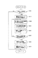
図12は、動作選択の際の液晶表示パネル15bの表示状況を示している。カメラ系ユニット60が装着されていれば、動作選択が行える。操作用スイッチ15aにより、セキュリティモードを選択すると、図13に示すフローチャートに従ってセキュリティモードの動作を実行する
セキュリティモードでは、ステップS400にて各人体センサ21fr,21rr,21fl,21rlの検知結果を入力する。いずれも人体を検知していないときは、一旦セキュリティーモードを終了し、他の処理を実施した後、定期的に本セキュリティモードを繰り返し起動することになる。
Even if the uncleaned areas are scattered in a plurality of places, the uncleaned areas are finally eliminated by repeating the detection of the uncleaned areas every time the termination condition of the cleaning traveling as described above is satisfied. .
Next, the operation in the security mode will be described.
FIG. 12 shows the display status of the liquid
ステップS400にていずれかの人体センサ21fr,21rr,21fl,21rlによって人体らしきものを検知した場合には、ステップS410にで無線LANモジュール71の電源と照明用LED64の電源をオンにする。セキュリティモードは家人の留守中は常に起動していなければならず、バッテリーで動作する本自走式掃除機においては節電の必要性が高い。このため、待機時は必須の構成装置のみを起動しておき、必要時に他の構成装置に通電するようにしている。無線LANモジュール71も待機時は通電しておらず、侵入者らしきものを検知した場合のみ通電する。
If any human body sensor 21fr, 21rr, 21fl, 21rl detects a human body in step S400, the wireless LAN module 71 and the
ステップS420では各人体センサ21fr,21rr,21fl,21rlの検知結果に基づいて検知物体と本体BDとの相対角度を検知する。各人体センサ21が赤外線発光動体における赤外線強度を出力する場合と、単に赤外線発光動体の有無を出力する場合とがある。 In step S420, the relative angle between the detected object and the main body BD is detected based on the detection results of the human body sensors 21fr, 21rr, 21fl, 21rl. There are cases where each human body sensor 21 outputs the infrared intensity of the infrared light emitting moving body and cases where the presence or absence of the infrared light emitting moving body is simply output.
赤外線強度を出力する場合、単一の人体センサ21だけが検知するのではなく、複数の人体センサ21が検知すると考えられる。この場合、強度の強い二つの人体センサ21の検知出力を得て、それぞれの対向方向に挟まれる90度の角度範囲内で赤外線発光動体の角度を検知する。この場合、二つの人体センサ21の検知出力の強度比を求め、同強度比を利用して予め実験して作成しておいたテーブルを参照する。このテーブルには強度比と角度との対応が関連づけて記憶されているので、同90度の範囲内での検知対象物の角度が判断でき、さらに検知出力を利用した二つの人体センサ21の取り付け位置に基づいて本体BDとの相対角度を求める。例えば、検知出力の強度の強い二つの人体センサ21が右側面の人体センサ21fr,21rrであり、かつ、強度比から90度の範囲内における人体センサ21frの側の30度の角度が上記テーブルから参照されたとすると、右側面の90度の範囲内で前方側の30度の角度であるから、本体正面に対しては、45度+30度=75度の相対角度ということになる。 When outputting the infrared intensity, it is considered that not only a single human sensor 21 but also a plurality of human sensors 21 detect it. In this case, the detection outputs of the two strong human body sensors 21 are obtained, and the angle of the infrared light emitting moving body is detected within an angle range of 90 degrees sandwiched between the opposing directions. In this case, the intensity ratio of the detection outputs of the two human body sensors 21 is obtained, and a table created by experiment in advance using the intensity ratio is referred to. Since the correspondence between the intensity ratio and the angle is stored in this table in association with each other, the angle of the object to be detected within the range of 90 degrees can be determined, and the attachment of the two human body sensors 21 using the detection output. Based on the position, a relative angle with the main body BD is obtained. For example, the two human body sensors 21 having high detection output intensity are the human body sensors 21fr and 21rr on the right side surface, and the angle of 30 degrees on the human body sensor 21fr side within the range of 90 degrees from the intensity ratio is from the above table. If it is referred to, the angle is 30 degrees on the front side within the range of 90 degrees on the right side surface, and therefore, relative to the front of the main body, the angle is 45 degrees + 30 degrees = 75 degrees.
一方、単に赤外線発光動体の有無を出力する場合は、基本的に本体BDに対する8つの相対角度だけを検知する。すなわち、いずれか一つの人体センサ21だけが検知出力を出した場合は、同検知出力を出力した人体センサ21の取付位置の角度を相対角度とし、二つの人体センサ21が検知出力を出した場合は、これら二つの人体センサ21の取付位置の中間の角度を相対角度とし、三つの人体センサ21が検知出力を出した場合は、人体センサ21の取付位置の角度を相対角度とする。すなわち、等間隔で複数の人体センサが取り付けられている場合、偶数個であれば中央の二つの人体センサの取付位置の中間であり、奇数個であれば中央の人体センサの取付位置となる。 On the other hand, when the presence / absence of an infrared light emitting moving object is simply output, basically only eight relative angles with respect to the main body BD are detected. That is, when only one of the human body sensors 21 outputs a detection output, the angle of the mounting position of the human body sensor 21 that outputs the detection output is a relative angle, and the two human body sensors 21 output the detection output. The relative angle is an intermediate angle between the mounting positions of the two human body sensors 21, and when the three human body sensors 21 output a detection output, the angle of the mounting position of the human body sensor 21 is the relative angle. That is, when a plurality of human body sensors are mounted at equal intervals, if the number is even, it is an intermediate position between the mounting positions of the center two human sensors, and if the number is odd, the center human sensor is mounted.
ステップS430では、同相対角度に本体BDの正面が対面するように左右の駆動輪を駆動させるポジショニングを行う。回転動作であるから、同じ場所でのターン動作であり、左右の駆動輪モータ42R,42Lを逆方向に所定の回転量だけ駆動させるようにモータドライバ41R,41Lに指示を与える。
In step S430, positioning is performed to drive the left and right drive wheels so that the front of the main body BD faces the same relative angle. Since it is a rotation operation, it is a turn operation at the same place, and an instruction is given to the
ステップS440では、ポジショニングを終了して二つのCMOSカメラ61,62に撮影指示を与え、撮影後にその撮像イメージデータを取得する。撮影の指示とデータの取得はバス14とカメラ通信I/O63を介して行なう。
撮像イメージデータの取得後、ステップS450では、無線LANモジュールでの通信が可能か否か、あるいは記憶領域がフルとなったかを判断し、いずれかがオンとなるまでステップS420〜S440を繰り返す。すなわち、無線LANモジュール71はステップS410にて電源オンとされるまで起動しておらず、起動して通信可能となるまでにはいくらかの時間がかかることが普通である。このため、最初の撮影直後に撮像イメージデータを送信できるとは限らず、一方、通信できるまで待機しているだけよりは、さらなる撮影をしておいた方が撮影ミスを防ぐことも可能となる。このため、通信可能となるまでは撮影を繰り返すことを選択している。
In step S440, the positioning is finished, a shooting instruction is given to the two
After acquiring the captured image data, in step S450, it is determined whether or not communication with the wireless LAN module is possible, or whether the storage area is full, and steps S420 to S440 are repeated until one of them is turned on. That is, the wireless LAN module 71 is not activated until the power is turned on in step S410, and it usually takes some time until the wireless LAN module 71 is activated and becomes communicable. For this reason, it is not always possible to transmit the captured image data immediately after the first shooting. On the other hand, it is possible to prevent shooting mistakes by further shooting rather than just waiting until communication is possible. . For this reason, it is selected to repeat photographing until communication is possible.
一方、撮影した撮像イメージデータは記憶しておく必要があり、記憶容量は有限であるから、待機している間は撮影し続けることが可能であるわけでもない。このため、記憶領域がフルとなってしまった場合は撮影を終える。
ステップS450にていずれかの条件が満たされたら、ステップS460にて無線LANで撮像イメージデータを送信し、ステップS470にて無線LANモジュールの電源と照明用LED64の電源をオフにする。その後は、再度、定期的に本セキュリティモードが起動され、さらなる監視を継続する。
On the other hand, the captured image data needs to be stored, and since the storage capacity is finite, it is not possible to continue shooting while waiting. For this reason, when the storage area becomes full, shooting is finished.
If any of the conditions is satisfied in step S450, the captured image data is transmitted by wireless LAN in step S460, and the power of the wireless LAN module and the
ところで、撮像イメージデータの取得は二つのCMOSカメラ61,62の両方から行うことが好ましい。しかしながら、ユーザの選択により、広角カメラで連続撮影をすることを選択したり、標準カメラで連続撮影をすることを選択するようにしても良い。また、変則的に、広角カメラでは一枚のみ撮影し、以後は標準カメラで撮影するようにしても良い。撮像イメージデータの転送に時間がかかる場合は、複数枚の撮像イメージデータを送信するのに要する時間を考慮すると、広角カメラの画像は一枚で十分であり、それよりも標準カメラの画像を複数枚取得した方が有意義である場合もあるからである。また、標準カメラでの撮影範囲が狭いことを補うため、撮影後、本体BDを少し回転させ、再度、撮影するということを繰り返しても良い。この場合、最初に上記相対角度をなくす方向に対面して撮影し、次に、この位置を基準としてわずかに左に回転して撮影し、その次に右に回転して撮影するというようにしてもよい。むろん、この振り幅を徐々に広げていって撮影範囲を広げていくようにしても良い。
By the way, it is preferable to acquire captured image data from both of the two
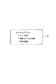
上述した例では撮像イメージデータを無線LAN経由で送信するようにしている。送信先は、サーバの所定領域であっても良いし、インターネットを介して電子メールの添付データとして送信することも可能である。この場合、図14に示すように、液晶表示パネル15bで、セキュリティオプションとして送信方法を選択できるようにしておく。同図に示す例では、「サーバ記憶」と、「無線LANで電子メール送信」と、「本体内記憶」とを表示しており、操作用スイッチ15aにていずれかを選択できるようにしている。そして、電子メールで送信する場合は、図15に示すように電子メール送信アドレスを設定できるようにしておく。
In the example described above, captured image data is transmitted via a wireless LAN. The transmission destination may be a predetermined area of the server, or can be transmitted as attachment data of an electronic mail via the Internet. In this case, as shown in FIG. 14, the transmission method can be selected as a security option on the liquid
また、上述した実施例では撮影と送信だけを行うようにしているが、撮影後、無線LANで送信できるようになるまでの間に、本体BDを破壊されかねない。従って、撮影後、退避行動を実行するようにしても良い。図16は退避行動を選択できるようにするための液晶表示パネル15bでの選択画面を示している。退避行動は、ジグザグに後退するようにしたり、あるいは予め決定しておいた退避場所へ逃げ込むというようにしてもよい。退避場所は本自走式掃除機が入り込める狭い隙間などがよい。
In the above-described embodiment, only photographing and transmission are performed. However, the main body BD may be destroyed after photographing until the wireless LAN can be transmitted. Therefore, the evacuation action may be executed after shooting. FIG. 16 shows a selection screen on the liquid
視野角と仰角を異にする複数のカメラ素子によって侵入者を撮影し、撮像イメージを入力し、同撮像イメージを所定の方法で出力するようにしたため、簡易な構成で撮影ミスを防止できる。 Since an intruder is photographed by a plurality of camera elements having different viewing angles and elevation angles, a captured image is input, and the captured image is output by a predetermined method, a photographing error can be prevented with a simple configuration.
10…制御ユニット
20…人体感知ユニット
30…障害物監視ユニット
40…走行系ユニット
50…クリーナ系ユニット
60…カメラ系ユニット
70…無線LANユニット
DESCRIPTION OF
Claims (10)
上記本体には、
標準の視野角の標準カメラ素子と広角の視野角の広角カメラ素子であって、同広角カメラ素子は視野角内に床面が入る仰角で固定され、同標準カメラ素子は同仰角よりも低めに固定されたカメラ素子と、
側面に複数備えられて赤外線の受光光量の変化に基づいて赤外線発光動体を検知する人体センサと、
この複数の人体センサの検知状況に基づいて上記本体に対する相対角度を検出し、同相対角度をなくすように上記本体の回転角度を変化させ、上記カメラ素子にて撮影を行わせ、無線LANモジュールにより所定のプロトコルに従って同撮影した撮像イメージデータを無線で外部に出力する制御手段とを具備することを特徴とする自走式掃除機。 A self-propelled cleaner comprising a main body provided with a cleaning mechanism, and a drive mechanism having drive wheels arranged on the left and right of the main body and capable of individually controlling rotation and realizing steering and driving,
In the main body,
A standard camera element with a standard viewing angle and a wide-angle camera element with a wide viewing angle. The wide-angle camera element is fixed at an elevation angle where the floor surface enters the viewing angle, and the standard camera element is lower than the elevation angle. A fixed camera element;
A human body sensor that is provided on the side surface and detects an infrared light emitting moving body based on a change in the amount of received light of infrared light,
Based on the detection status of the plurality of human body sensors, a relative angle with respect to the main body is detected, the rotation angle of the main body is changed so as to eliminate the relative angle, photographing is performed with the camera element, and a wireless LAN module is used. A self-propelled cleaner comprising: control means for wirelessly outputting the captured image data taken in accordance with a predetermined protocol to the outside.
上記本体には、それぞれ視野角が異なるとともに、仰角を異ならせて配置された複数のカメラ素子と、
本体の周囲における人体の有無を検知して検知方向を取得することが可能な人体センサと、
上記人体センサの検知結果に基づいて検知された人体の方向に上記本体を対面させた後、上記複数のカメラ素子のそれぞれで撮影して撮像イメージを入力し、同撮像イメージを所定の方法で出力する制御手段とを有することを特徴とする自走式掃除機。 A self-propelled cleaner comprising a main body provided with a cleaning mechanism and a drive mechanism capable of steering and driving,
The main body has a plurality of camera elements arranged with different viewing angles and different elevation angles, and
A human body sensor capable of detecting the presence or absence of a human body around the body and obtaining a detection direction;
After facing the main body in the direction of the human body detected based on the detection result of the human body sensor, each of the plurality of camera elements captures and inputs a captured image, and outputs the captured image by a predetermined method The self-propelled cleaner characterized by having the control means to do.
Priority Applications (2)
| Application Number | Priority Date | Filing Date | Title |
|---|---|---|---|
| JP2004121743A JP2005304540A (en) | 2004-04-16 | 2004-04-16 | Self-running type vacuum cleaner equipped with monitoring camera |
| US11/107,174 US20050237388A1 (en) | 2004-04-16 | 2005-04-15 | Self-propelled cleaner with surveillance camera |
Applications Claiming Priority (1)
| Application Number | Priority Date | Filing Date | Title |
|---|---|---|---|
| JP2004121743A JP2005304540A (en) | 2004-04-16 | 2004-04-16 | Self-running type vacuum cleaner equipped with monitoring camera |
Publications (1)
| Publication Number | Publication Date |
|---|---|
| JP2005304540A true JP2005304540A (en) | 2005-11-04 |
Family
ID=35135980
Family Applications (1)
| Application Number | Title | Priority Date | Filing Date |
|---|---|---|---|
| JP2004121743A Withdrawn JP2005304540A (en) | 2004-04-16 | 2004-04-16 | Self-running type vacuum cleaner equipped with monitoring camera |
Country Status (2)
| Country | Link |
|---|---|
| US (1) | US20050237388A1 (en) |
| JP (1) | JP2005304540A (en) |
Cited By (10)
| Publication number | Priority date | Publication date | Assignee | Title |
|---|---|---|---|---|
| KR100769909B1 (en) * | 2006-09-06 | 2007-10-24 | 엘지전자 주식회사 | Robot cleaner and operating method thereof |
| JP2008147756A (en) * | 2006-12-06 | 2008-06-26 | Nippon Telegr & Teleph Corp <Ntt> | Mobile phone |
| KR20100092254A (en) * | 2009-02-12 | 2010-08-20 | 삼성전자주식회사 | Light emitting device and portable terminal using the same |
| WO2016009585A1 (en) * | 2014-07-18 | 2016-01-21 | パナソニックIpマネジメント株式会社 | Autonomous mobile object and method of controlling same |
| JP2016041201A (en) * | 2014-08-18 | 2016-03-31 | 株式会社東芝 | Vacuum cleaner and cleaning system |
| JP2016051343A (en) * | 2014-08-29 | 2016-04-11 | 株式会社東芝 | Autonomous traveling body |
| KR101938668B1 (en) | 2017-05-29 | 2019-01-15 | 엘지전자 주식회사 | Cleaner and controlling method thereof |
| JP2019516506A (en) * | 2016-05-20 | 2019-06-20 | エルジー エレクトロニクス インコーポレイティド | Robot vacuum cleaner |
| US10827896B2 (en) | 2016-05-20 | 2020-11-10 | Lg Electronics Inc. | Autonomous cleaner |
| US20210034069A1 (en) * | 2017-07-21 | 2021-02-04 | Lg Electronics Inc. | Cleaner and control method thereof |
Families Citing this family (27)
| Publication number | Priority date | Publication date | Assignee | Title |
|---|---|---|---|---|
| US9082456B2 (en) | 2005-01-31 | 2015-07-14 | The Invention Science Fund I Llc | Shared image device designation |
| US9910341B2 (en) | 2005-01-31 | 2018-03-06 | The Invention Science Fund I, Llc | Shared image device designation |
| US9489717B2 (en) | 2005-01-31 | 2016-11-08 | Invention Science Fund I, Llc | Shared image device |
| US20060170956A1 (en) | 2005-01-31 | 2006-08-03 | Jung Edward K | Shared image devices |
| US9325781B2 (en) | 2005-01-31 | 2016-04-26 | Invention Science Fund I, Llc | Audio sharing |
| US9124729B2 (en) | 2005-01-31 | 2015-09-01 | The Invention Science Fund I, Llc | Shared image device synchronization or designation |
| US9451200B2 (en) | 2005-06-02 | 2016-09-20 | Invention Science Fund I, Llc | Storage access technique for captured data |
| US20070008326A1 (en) * | 2005-06-02 | 2007-01-11 | Searete Llc, A Limited Liability Corporation Of The State Of Delaware | Dual mode image capture technique |
| US9819490B2 (en) | 2005-05-04 | 2017-11-14 | Invention Science Fund I, Llc | Regional proximity for shared image device(s) |
| US8964054B2 (en) | 2006-08-18 | 2015-02-24 | The Invention Science Fund I, Llc | Capturing selected image objects |
| US9076208B2 (en) | 2006-02-28 | 2015-07-07 | The Invention Science Fund I, Llc | Imagery processing |
| US9621749B2 (en) | 2005-06-02 | 2017-04-11 | Invention Science Fund I, Llc | Capturing selected image objects |
| US9191611B2 (en) | 2005-06-02 | 2015-11-17 | Invention Science Fund I, Llc | Conditional alteration of a saved image |
| US9001215B2 (en) | 2005-06-02 | 2015-04-07 | The Invention Science Fund I, Llc | Estimating shared image device operational capabilities or resources |
| US20070222865A1 (en) | 2006-03-15 | 2007-09-27 | Searete Llc, A Limited Liability Corporation Of The State Of Delaware | Enhanced video/still image correlation |
| US10003762B2 (en) | 2005-04-26 | 2018-06-19 | Invention Science Fund I, Llc | Shared image devices |
| US9967424B2 (en) | 2005-06-02 | 2018-05-08 | Invention Science Fund I, Llc | Data storage usage protocol |
| US8432448B2 (en) * | 2006-08-10 | 2013-04-30 | Northrop Grumman Systems Corporation | Stereo camera intrusion detection system |
| US8792005B2 (en) * | 2006-11-29 | 2014-07-29 | Honeywell International Inc. | Method and system for automatically determining the camera field of view in a camera network |
| KR102094347B1 (en) | 2013-07-29 | 2020-03-30 | 삼성전자주식회사 | Auto-cleaning system, cleaning robot and controlling method thereof |
| JP6452386B2 (en) * | 2014-10-29 | 2019-01-16 | キヤノン株式会社 | Imaging apparatus, imaging system, and imaging apparatus control method |
| CN105430355B (en) * | 2015-12-31 | 2018-07-06 | 重庆房地产职业学院 | A kind of half hidden monitoring device of green intelligent |
| US10245730B2 (en) * | 2016-05-24 | 2019-04-02 | Asustek Computer Inc. | Autonomous mobile robot and control method thereof |
| TWI634403B (en) * | 2017-01-26 | 2018-09-01 | 好樣科技有限公司 | An automatic cleaning robot and a controlling method of the same |
| DE102017208962B3 (en) * | 2017-05-29 | 2018-11-15 | BSH Hausgeräte GmbH | Cleaning robot with an additive for changing the optical properties of a camera optics |
| US11890747B2 (en) | 2018-09-26 | 2024-02-06 | Disney Enterprises, Inc. | Interactive autonomous robot configured with in-character safety response protocols |
| US11416002B1 (en) * | 2019-06-11 | 2022-08-16 | Ambarella International Lp | Robotic vacuum with mobile security function |
-
2004
- 2004-04-16 JP JP2004121743A patent/JP2005304540A/en not_active Withdrawn
-
2005
- 2005-04-15 US US11/107,174 patent/US20050237388A1/en not_active Abandoned
Cited By (22)
| Publication number | Priority date | Publication date | Assignee | Title |
|---|---|---|---|---|
| KR100769909B1 (en) * | 2006-09-06 | 2007-10-24 | 엘지전자 주식회사 | Robot cleaner and operating method thereof |
| WO2008030054A1 (en) * | 2006-09-06 | 2008-03-13 | Lg Electronics Inc. | Moving robot and operating method thereof |
| US8560120B2 (en) | 2006-09-06 | 2013-10-15 | Lg Electronics Inc. | Moving robot and operating method thereof |
| JP2008147756A (en) * | 2006-12-06 | 2008-06-26 | Nippon Telegr & Teleph Corp <Ntt> | Mobile phone |
| KR20100092254A (en) * | 2009-02-12 | 2010-08-20 | 삼성전자주식회사 | Light emitting device and portable terminal using the same |
| KR101679067B1 (en) * | 2009-02-12 | 2016-11-23 | 삼성전자주식회사 | Light emitting device and portable terminal using the same |
| WO2016009585A1 (en) * | 2014-07-18 | 2016-01-21 | パナソニックIpマネジメント株式会社 | Autonomous mobile object and method of controlling same |
| JPWO2016009585A1 (en) * | 2014-07-18 | 2017-04-27 | パナソニックIpマネジメント株式会社 | Autonomous mobile object and its control method |
| JP2016041201A (en) * | 2014-08-18 | 2016-03-31 | 株式会社東芝 | Vacuum cleaner and cleaning system |
| JP2016051343A (en) * | 2014-08-29 | 2016-04-11 | 株式会社東芝 | Autonomous traveling body |
| US10856714B2 (en) | 2016-05-20 | 2020-12-08 | Lg Electronics Inc. | Autonomous cleaner |
| JP2019516506A (en) * | 2016-05-20 | 2019-06-20 | エルジー エレクトロニクス インコーポレイティド | Robot vacuum cleaner |
| US10827896B2 (en) | 2016-05-20 | 2020-11-10 | Lg Electronics Inc. | Autonomous cleaner |
| US10827895B2 (en) | 2016-05-20 | 2020-11-10 | Lg Electronics Inc. | Autonomous cleaner |
| US10835095B2 (en) | 2016-05-20 | 2020-11-17 | Lg Electronics Inc. | Autonomous cleaner |
| US10939792B2 (en) | 2016-05-20 | 2021-03-09 | Lg Electronics Inc. | Autonomous cleaner |
| US11547263B2 (en) | 2016-05-20 | 2023-01-10 | Lg Electronics Inc. | Autonomous cleaner |
| US11846937B2 (en) | 2016-05-20 | 2023-12-19 | Lg Electronics Inc. | Autonomous cleaner |
| KR101938668B1 (en) | 2017-05-29 | 2019-01-15 | 엘지전자 주식회사 | Cleaner and controlling method thereof |
| US11412907B2 (en) | 2017-05-29 | 2022-08-16 | Lg Electronics Inc. | Cleaner and controlling method thereof |
| US20210034069A1 (en) * | 2017-07-21 | 2021-02-04 | Lg Electronics Inc. | Cleaner and control method thereof |
| US11759075B2 (en) * | 2017-07-21 | 2023-09-19 | Lg Electronics Inc. | Cleaner and control method thereof |
Also Published As
| Publication number | Publication date |
|---|---|
| US20050237388A1 (en) | 2005-10-27 |
Similar Documents
| Publication | Publication Date | Title |
|---|---|---|
| JP2005304540A (en) | Self-running type vacuum cleaner equipped with monitoring camera | |
| JP2005296510A (en) | Self-traveling vacuum cleaner with monitor camera | |
| JP3832593B2 (en) | Self-propelled vacuum cleaner | |
| US20050234611A1 (en) | Self-propelled cleaner | |
| US20050273226A1 (en) | Self-propelled cleaner | |
| CN100506141C (en) | External recharging device robot cleaner | |
| US20050212680A1 (en) | Self-propelled cleaner | |
| JP3992026B2 (en) | Self-propelled robot | |
| KR20070045475A (en) | The apparatus and method for controlling the camera of robot cleaner | |
| JP2004148088A (en) | Robot cleaner, system and control method therefor | |
| KR101834678B1 (en) | Autonomous traveling body | |
| JP2005296511A (en) | Self-propelled vacuum cleaner | |
| JP2016042285A (en) | Autonomous mobile body | |
| SE523438C2 (en) | Mobile robot system using RF module | |
| KR100946175B1 (en) | Pan-tilting apparatus | |
| JP2005275898A (en) | Self-propelled cleaner | |
| JP2006043175A (en) | Self-travelling vacuum cleaner | |
| JP2006095005A (en) | Self-propelled vacuum cleaner | |
| JP2005216022A (en) | Autonomous run robot cleaner | |
| JP2007317112A (en) | Self-propelled device and self-propelled cleaner | |
| JP3721939B2 (en) | Mobile work robot | |
| JP2006139525A (en) | Autonomous mobile robot | |
| JP2007303913A (en) | Foreign matter detecting device, robot device using the same, foreign matter detection method, and foreign matter detection program | |
| JP2005271152A (en) | Self-running vacuum cleaner and self-running robot | |
| JP2005304515A (en) | Self-traveling vacuum cleaner |
Legal Events
| Date | Code | Title | Description |
|---|---|---|---|
| RD04 | Notification of resignation of power of attorney |
Free format text: JAPANESE INTERMEDIATE CODE: A7424 Effective date: 20051221 |
|
| A761 | Written withdrawal of application |
Free format text: JAPANESE INTERMEDIATE CODE: A761 Effective date: 20060915 |