JP2005304512A - Medical apparatus - Google Patents
Medical apparatus Download PDFInfo
- Publication number
- JP2005304512A JP2005304512A JP2004121422A JP2004121422A JP2005304512A JP 2005304512 A JP2005304512 A JP 2005304512A JP 2004121422 A JP2004121422 A JP 2004121422A JP 2004121422 A JP2004121422 A JP 2004121422A JP 2005304512 A JP2005304512 A JP 2005304512A
- Authority
- JP
- Japan
- Prior art keywords
- time
- display device
- display
- receiving
- information
- Prior art date
- Legal status (The legal status is an assumption and is not a legal conclusion. Google has not performed a legal analysis and makes no representation as to the accuracy of the status listed.)
- Pending
Links
Images

Abstract
Description
本発明は、被検体内情報を受信する受信装置と、この被検体内情報による画像を表示する表示装置とからなる医療装置に関し、特に受信装置と表示装置の時刻合わせを行う医療装置に関するものである。 The present invention relates to a medical device including a receiving device that receives in-subject information and a display device that displays an image based on the in-subject information, and more particularly to a medical device that performs time adjustment of the receiving device and the display device. is there.
近年、内視鏡の分野では、撮像機能と無線通信機能とが装備されたカプセル型内視鏡が登場している。このカプセル型内視鏡は、観察(検査)のために被検体である被検者の口から飲み込まれた後、被検者の生体から自然排出されるまでの観察期間、たとえば胃、小腸などの臓器の内部(体腔内)をその蠕動運動に伴って移動し、撮像機能を用いて順次撮像する構成を有する。 In recent years, in the field of endoscopes, capsule endoscopes equipped with an imaging function and a wireless communication function have appeared. This capsule endoscope is an observation period after it is swallowed from the subject's mouth, which is a subject for observation (examination), until it is naturally discharged from the subject's body, for example, the stomach, the small intestine, etc. The internal organs (inside the body cavity) move with the peristaltic movement, and images are sequentially captured using the imaging function.
また、これら臓器内を移動するこの観察期間、カプセル型内視鏡によって体腔内で撮像された画像データは、順次無線通信などの無線通信機能により、被検体の外部に送信され、外部の受信装置内に設けられたメモリに蓄積される。被検者がこの無線通信機能とメモリ機能を備えた受信装置を携帯することにより、被検者は、カプセル型内視鏡を飲み込んだ後、排出されるまでの観察期間であっても、不自由を被ることなく自由に行動が可能になる。観察後は、医者もしくは看護士によって、受信装置のメモリに蓄積された画像データに基づいて、体腔内の画像をディスプレイなどの表示手段に表示させて診断を行うことができる。 Also, during this observation period of moving through these organs, image data imaged in the body cavity by the capsule endoscope is sequentially transmitted to the outside of the subject by a wireless communication function such as wireless communication, and an external receiving device It is stored in a memory provided in the inside. When the subject carries the receiving device equipped with the wireless communication function and the memory function, the subject is incapable of performing the observation even during the observation period from swallowing the capsule endoscope until it is discharged. It is possible to act freely without incurring freedom. After the observation, a doctor or a nurse can make a diagnosis by displaying an image in the body cavity on a display means such as a display based on the image data stored in the memory of the receiving device.
一般に、受信装置は、カプセル型内視鏡から送信される映像信号を受信するための複数のアンテナを被検体外部に分散配置し、映像信号の受信誤りが少ない1つのアンテナを選択切り替えして受信するようにしている。なお、特許文献1には、受信装置で受信された画像データに、時刻などの付加情報を付加してワークステーションなどの表示装置に記録する生体内画像装置が記載されている。一般に、受信装置と表示装置は、時刻を計時するタイマなどの計時機能を有し、検査の開始時刻と終了時刻は、表示装置が定め、画像データの取得時刻は、受信装置が定めて、この画像データに付加している。
In general, a receiving device distributes and arranges a plurality of antennas for receiving a video signal transmitted from a capsule endoscope outside a subject, and selectively switches and receives one antenna with few video signal reception errors. Like to do.
しかしながら、この生体内画像装置では、受信装置と表示装置とで時刻合わせのための調整を行なっていないので、たとえばこの画像データの取得時刻をファイル名に設定した場合に、受信装置のタイマの時刻と、表示装置のタイマの時刻とが異なっていると、表示装置側では、検査の時刻情報と画像データに付加された取得時刻情報との整合性がとれなくなって、適切な画像データの選出や表示を行うことができなくなることがあった。 However, since this in-vivo image device does not perform adjustment for time adjustment between the receiving device and the display device, for example, when the acquisition time of the image data is set as a file name, the time of the timer of the receiving device If the time of the timer of the display device is different, the display device side cannot match the time information of the inspection and the acquisition time information added to the image data, and the appropriate image data can be selected. In some cases, the display could not be performed.
本発明は、上記問題に鑑みてなされたものであって、受信装置と表示装置の時刻調整を行なって、検査の時刻情報と画像データに付加された時刻情報との整合性をとって、適切な画像データの選出および表示を行うことができる医療装置を提供することを目的とする。 The present invention has been made in view of the above problems, and performs time adjustment between the receiving device and the display device to ensure consistency between the time information of the inspection and the time information added to the image data. An object of the present invention is to provide a medical device capable of selecting and displaying various image data.
上述した課題を解決し、目的を達成するために、本発明にかかる医療装置は、移動する送信装置から送信される無線映像信号を受信する受信装置と、前記受信装置が受信した無線映像信号に基づいた画像を表示する表示装置とからなる医療装置において、前記表示装置は、時刻を計時する第1の計時手段と、前記計時された時刻情報を送出する送出手段と、を備え、前記受信装置は、時刻を計時する第2の計時手段と、前記送出手段からの時刻情報に基づいて、前記第2の計時手段の時刻設定を行う第2の時刻設定手段と、を備えることを特徴とする。 In order to solve the above-described problems and achieve the object, a medical device according to the present invention includes a receiving device that receives a wireless video signal transmitted from a moving transmitting device, and a wireless video signal received by the receiving device. In the medical device comprising a display device for displaying an image based on the display device, the display device includes first time measuring means for measuring time, and sending means for sending the time information measured, and the receiving apparatus Comprises second time measuring means for measuring time and second time setting means for setting the time of the second time measuring means based on time information from the sending means. .
また、請求項2の発明にかかる医療装置は、上記発明において、前記表示装置は、外部からの時刻情報に基づいて、前記第1の計時手段の時刻設定を行う第1の時刻設定手段を、さらに備えることを特徴とする。 The medical device according to a second aspect of the present invention is the medical device according to the above invention, wherein the display device includes first time setting means for setting the time of the first time measuring means based on time information from outside. It is further provided with the feature.
また、請求項3の発明にかかる医療装置は、上記発明において、前記送信装置は、検査対象の被検体内から取得された被検体内情報を、無線送信し、前記受信装置は、前記第2の計時手段によって前記被検体内情報の取得時間を設定し、前記表示装置は、前記被検体内情報に基づくサムネイル画像の表示が可能な表示手段と、前記第1の計時手段によって前記検査の開始時刻と終了時刻を設定するとともに、前記開始時刻と前記終了時刻と前記受信装置で設定された前記取得時間に基づいて、前記サムネイル画像の表示の有無を判断する判断手段と、前記判断手段の判断結果に基づいて、前記サムネイル画像を作成する作成手段と、をさらに備えることを特徴とする。 In the medical device according to a third aspect of the present invention, in the above invention, the transmitting device wirelessly transmits in-subject information acquired from within the subject to be examined, and the receiving device is the second device. The acquisition time of the in-subject information is set by the time measuring means, and the display device displays the thumbnail image based on the in-subject information, and starts the examination by the first time measuring means. A determination unit configured to determine whether or not to display the thumbnail image based on the start time, the end time, and the acquisition time set by the reception device; And a creation means for creating the thumbnail image based on the result.
また、請求項4の発明にかかる医療装置は、上記発明において、前記受信装置は、前記画像に受信時刻を付加する時刻付加手段を、さらに備えることを特徴とする請求項1〜3のいずれか一つに記載の医療装置。 The medical device according to a fourth aspect of the present invention is the medical device according to any one of the first to third aspects, further comprising a time adding unit that adds a reception time to the image. The medical device according to one.
本発明にかかる医療装置は、表示装置の第1の計時手段が計時する時刻に基づいて、受信装置の第2の計時手段の時刻設定を行なうことで、受信装置と表示装置の時刻調整を行なって、検査の時刻情報と画像データに付加された時刻情報との整合性をとって、適切な画像データの選出および表示を行うことができるという効果を奏する。 The medical device according to the present invention adjusts the time of the receiving device and the display device by setting the time of the second time measuring device of the receiving device based on the time measured by the first time measuring device of the display device. Thus, there is an effect that it is possible to select and display appropriate image data by matching the time information of the inspection and the time information added to the image data.
以下に、本発明にかかる医療装置の実施の形態を図1〜図7の図面に基づいて詳細に説明する。なお、本発明は、これらの実施の形態に限定されるものではなく、本発明の要旨を逸脱しない範囲で種々の変更実施の形態が可能である。 Hereinafter, embodiments of a medical device according to the present invention will be described in detail based on the drawings of FIGS. The present invention is not limited to these embodiments, and various modifications can be made without departing from the scope of the present invention.
(実施の形態1)
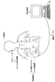
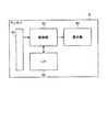
図1は、本発明にかかる医療装置を備えた無線型被検体内情報取得システムの全体構成を示す模式図である。図1において、無線型被検体内情報取得システムは、無線受信機能を有する受信装置2と、被検体1内に導入され、体腔内画像を撮像して受信装置2に対して映像信号などのデータ送信を行うカプセル型内視鏡(被検体内導入装置)3とを備える。また、無線型被検体内情報取得システムは、受信装置2が受信した映像信号に基づいて体腔内画像を表示する表示装置4と、受信装置2と表示装置4との間でデータの受け渡しを行うための通信ケーブル5とを備える。受信装置2は、被検体1によって着用される受信ジャケット2aと、受信される無線信号の処理などを行う外部装置2bとを備える。なお、受信装置2、表示装置4および通信ケーブル5は、医療装置を構成している。
(Embodiment 1)
FIG. 1 is a schematic diagram showing an overall configuration of a wireless in-vivo information acquiring system including a medical device according to the present invention. In FIG. 1, a wireless in-vivo information acquisition system includes a
表示装置4は、カプセル型内視鏡3によって撮像された体腔内画像などを表示するためのものであり、通信ケーブル5を介して受信装置2から得られるデータに基づいて画像表示を行うワークステーションなどのような構成を有する。具体的には、表示装置4は、CRTディスプレイ、液晶ディスプレイなどによって直接画像を表示する構成としても良いし、プリンタなどのように、他の媒体に画像を出力する構成としても良い。
The display device 4 is for displaying an in-vivo image picked up by the
通信ケーブル5は、通常、外部装置2bおよび表示装置4に対して着脱可能であって、両者に対して挿着された時に外部装置2bはデータ情報の出力または記録が可能な構造を有する。この実施の形態では、通信ケーブル5は、受信装置2を初期化、たとえば以前の検査で記憶部13に記憶された画像データなどの古いデータの削除や、患者識別情報および検査日などの検査IDの登録を行うときに、外部装置2bと表示装置4間に接続され、表示装置4からのデータを外部装置2bに送信する。次に、初期化が終了すると、外部装置2bと表示装置4間から取り外され、両者の接続を断状態にする。カプセル型内視鏡3が被検体1の体腔内を移動している間は、両者の接続は断状態を維持する。また、外部装置2bは、カプセル型内視鏡が無線送信したデータを受信し、記録する。そして、カプセル型内視鏡3が被検体1から排出された後、つまり、被検体1の内部の撮像が終了した後には、通信ケーブル5は、外部装置2bと表示装置4間に接続され、外部装置2bで記録されたカプセル型内視鏡3から送信されたデータが、この表示装置4によって、読み出される構成を有する。なお、本発明にかかる外部装置2bと表示装置4との通信は、上記通信ケーブル5に限らず、無線接続によって行うことも可能であり、またはデータの同期が可能なクレードルを用いて外部装置2bと表示装置4を接続させて通信することも可能である。この場合には表示装置とクレードルを通信ケーブルで接続し、このクレードル上に外部装置2bを載置させて、外部装置2bと表示装置4間でのデータ転送を行うように構成する。
The
次に、図2のブロック図を用いて受信装置の構成について説明する。受信装置2は、カプセル型内視鏡3から無線送信された体腔内の画像データを受信する機能を有する。図2に示すように、受信装置2は、被検体1によって着用可能な形状を有し、受信用アンテナA1〜Anを備えた受信ジャケット2aと、受信ジャケット2aを介して受信された無線信号の処理などを行う外部装置2bとを備える。なお、各受信用アンテナA1〜Anは、直接被検体(人体)1の外表面に貼付して、受信ジャケット2aに備え付けられなくてもよく、また受信ジャケット2aに着脱可能なものでもよい。
Next, the configuration of the receiving apparatus will be described with reference to the block diagram of FIG. The
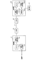
外部装置2bは、カプセル型内視鏡3から送信された無線信号の処理を行う機能を有する。すなわち、外部装置2bは、図3に示すように、各受信用アンテナA1〜Anの接続切り替えを行う切替スイッチSWと、この切替スイッチSWの後段に接続され、切替スイッチSWによって切り替え接続された受信用アンテナA1〜Anからの無線信号を増幅し、復調する受信回路11とを有し、さらに受信回路11の後段には、信号処理回路12と、サンプルホールド回路15とが接続される。サンプルホールド回路15の後段には、さらにA/D変換部16が接続される。
The
制御部Cは、制御手段としての選択制御部C1を有し、信号処理回路12、A/D変換部16、画像データを記憶するハードディスクなどからなる記憶部13、表示部14、インターフェース部18および切替制御部SCを接続する。切替制御部SCは、強度受信アンテナ番号N1および映像受信アンテナ番号N2を有し、これらの番号情報をもとに、切替スイッチSWの切替指示を行うとともに、サンプルホールド回路15、A/D変換部16および選択制御部C1の処理タイミングを指示する。また、インターフェース部18は、図示しない接続部を介して通信ケーブル5と接続されている。制御部Cは、図示しない内部メモリを有し、このインターフェース部18を介して通信ケーブル5から入力する検査IDなどの被検者を識別する識別情報をこの内部メモリに登録する。電力供給部17は、たとえば市販の乾電池からなり、上述した各内部機器への電力供給を行う。
The control unit C includes a selection control unit C1 as a control unit, and includes a
外部装置2bの切替スイッチSWは、切替制御部SCからの切替指示に基づき、受信用アンテナA1〜Anからの無線信号を受信回路11に出力する。ここで、切替スイッチSWは、受信用アンテナA1〜Anの配置位置にそれぞれ対応して各受信用アンテナA1〜Anを接続するアンテナ切替手段としての接続部CONを有する。
The change-over switch SW of the
この接続部CONは、各コネクタCON1〜CONnの接続状態を検知する検知機能を有している。たとえば、コネクタCON1に対して、接続部CONは、アンテナ未接続検知部を有しており、コネクタCON1が接続部CONに接続された時に、検知信号としての電圧信号が選択制御部C1に出力される構成を備えており、他のコネクタCON2〜CONnに対しても同様なアンテナ未接続検知部を有する。したがって、選択制御部C1は、この電圧信号の有無を検知することによって、コネクタCON1、すなわち受信用アンテナA1が接続されているか否かを判断することができる。同様な検知部を各コネクタCON2〜CONnに対応させて持たせることによって、選択制御部C1は、各受信用アンテナA1〜Anの接続状態の有無を判別することができる。 The connection part CON has a detection function for detecting the connection state of the connectors CON1 to CONn. For example, for the connector CON1, the connection part CON has an antenna non-connection detection part, and when the connector CON1 is connected to the connection part CON, a voltage signal as a detection signal is output to the selection control part C1. The other connectors CON2 to CONn have the same antenna unconnected detector. Therefore, the selection control unit C1 can determine whether or not the connector CON1, that is, the receiving antenna A1 is connected, by detecting the presence or absence of the voltage signal. By providing a similar detection unit corresponding to each of the connectors CON2 to CONn, the selection control unit C1 can determine whether or not each reception antenna A1 to An is connected.
さて、図2において、受信回路11は、上述したように、無線信号を増幅し、復調した映像信号S1を信号処理回路12に出力するとともに、増幅した無線信号の受信電界強度である受信強度信号S2をサンプルホールド回路15に出力する。信号処理回路12によって処理された映像データは、制御部Cによって記憶部13に記憶されるとともに、表示部14によって表示出力される。サンプルホールド回路15によってサンプルホールドされた信号は、A/D変換部16によってデジタル信号に変換され、制御部Cに取り込まれ、最も大きい受信電界強度を受信した受信用アンテナを映像信号期間の受信用アンテナとして選択するとともに、この選択された受信用アンテナ以外の受信用アンテナを順次、強度受信期間の受信用アンテナとして選択し、それぞれの受信用アンテナ番号を、映像受信アンテナ番号N2、強度受信アンテナ番号N1とする信号S4として切替制御部SCに出力する。ここで、選択制御部C1が切替対象の受信用アンテナとして設定するのは、信号S6をもとに現に接続された受信用アンテナA1〜Anのみを対象とする。また、制御部Cは、強度受信期間の受信電界強度および映像受信期間の受信電界強度を、そのとき選択された受信用アンテナと対応付けて映像データとともに記憶部13に記憶する。この記憶された各受信用アンテナの受信電界強度は、映像データが受信されたときの体腔内のカプセル型内視鏡3の位置を算出するための情報となる。
In FIG. 2, the receiving
切替制御部SCは、選択制御部C1に指示された強度受信アンテナ番号N1と映像受信アンテナ番号N2とを保持し、強度受信期間には強度受信アンテナ番号N1に対応する受信用アンテナA1〜Anを選択接続するように切替スイッチSWに指示し、映像受信期間には映像受信アンテナ番号N2に対応する受信用アンテナA1〜Anを選択接続するように、切替スイッチSWに指示する信号S5を切替スイッチSWに出力するとともに、サンプルホールド回路15によるサンプルホールドタイミングを指示する信号S3a、A/D変換部16によるA/D変換タイミングを指示する信号S3b、選択制御部C1による選択制御タイミングを指示する信号S3cを出力する。
The switching control unit SC holds the strength receiving antenna number N1 and the video receiving antenna number N2 instructed by the selection control unit C1, and sets the receiving antennas A1 to An corresponding to the strength receiving antenna number N1 during the strength receiving period. The switch SW is instructed to make a selective connection, and a signal S5 instructing the changeover switch SW to make a selective connection to the receiving antennas A1 to An corresponding to the video receiving antenna number N2 during the video reception period. , A signal S3a for instructing the sample / hold timing by the sample / hold circuit 15, a signal S3b for instructing the A / D conversion timing by the A /
図3は、図1に示した外部装置と表示装置の要部を示すブロック図である。外部装置2bの制御部Cは、上述した選択制御部C1の他に、時刻を計時する第2の計時手段としてのタイマC2と、このタイマの時刻設定を行う第2の時刻設定手段としての時刻設定部C3と、画像処理された画像データに受信時刻を付加する時刻付加部C4とを備え、インターフェース部18および通信ケーブル5を介して表示装置4のインターフェース部42と接続されている。表示装置4の制御部DCは、第1の計時手段としてのタイマDC1と、第1の時刻設定手段としての時刻設定部DC2とを備える。この構成において、時刻設定部DC2は、インターフェース部42を介してたとえば時刻設定部C3と同期をとって、タイマDC1の時刻情報をこの時刻設定部C3に送出しており、時刻設定部C3は、入力する時刻情報に基づいて、タイマC2の時刻設定を行って、表示装置のタイマDC1と外部装置のタイマC2との時刻調整を可能にしている。
FIG. 3 is a block diagram showing the main parts of the external device and the display device shown in FIG. The control unit C of the
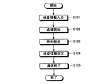
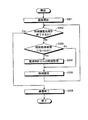
次に、図4のフローチャートに基づいて、図3に示した表示装置の時刻設定動作を説明する。図4において、まず図示しない情報入力手段(たとえばキーボードなど)から検査情報の入力があると(ステップ102)、制御部DCは、通信ケーブル5を介して外部装置2bの制御部Cと初期設定のための通信を開始する(ステップ102)。
Next, the time setting operation of the display device shown in FIG. 3 will be described based on the flowchart of FIG. In FIG. 4, first, when inspection information is input from an information input means (not shown) (for example, a keyboard) (step 102), the control unit DC communicates with the control unit C of the
次に、時刻設定部DC2は、時刻設定部C3と同期をとって、タイマDC1の時刻情報を時刻設定部C3に送出して、タイマC2の時刻設定を行わせ(ステップ103)、さらに制御部DCは、上記入力した検査情報を制御部Cに送出して、検査情報の設定を行わせ(ステップ104)、初期設定の通信を終了する(ステップ105)。ここでいう検査情報の設定とは、たとえば、外部装置2bの記憶部13を初期化し、検査情報(患者名、患者ID、検査日、検査時間など)を記憶部13に記憶することを示す。
Next, the time setting unit DC2 synchronizes with the time setting unit C3, sends the time information of the timer DC1 to the time setting unit C3, and sets the time of the timer C2 (step 103), and further the control unit The DC sends the input inspection information to the control unit C, sets the inspection information (step 104), and terminates the initial setting communication (step 105). The setting of the examination information here means, for example, that the
この初期設定が終了すると、カプセル型内視鏡3の検査が開始可能となる。そして、検査によってカプセル型内視鏡3から受信装置が受信した映像信号は、信号処理回路12で画像処理されて画像データとして制御部Cに出力される。制御部Cでは、この画像データを取り込むと、時刻付加部C4がタイマC2から画像取得時刻を検出して、この画像取得時刻情報を画像データに付加、たとえば画像データのファイル名として付加し、たとえば記憶部13に記録させ、検査が終了した後に、制御部Cは、この画像取得時刻が付加された画像データを、インターフェース部18を介して表示装置の制御部DCに送出することで、画像データの受け渡しおよび表示部41での画像表示を可能にする。なお、記憶部13は、たとえばコンパクトフラッシュ(登録商標)メモリなどからなる携帯型記録媒体で構成することも可能であり、この場合には、検査が終了した後に、受信装置2から取り外して、表示装置4に装着させることで、画像データの受け渡しおよび表示部41での画像表示を可能にする。
When this initial setting is completed, the inspection of the
このように、この医療装置では、表示装置のタイマが計時する時刻に基づいて、受信装置のタイマの時刻設定を行って、両タイマの時刻合わせを行うので、受信装置と表示装置の時刻調整が可能となって、検査の時刻情報と画像データに付加された画像取得時刻情報との整合性をとって、適切な画像データの選出および表示を行うことができる。さらに、この実施の形態では、検査の時刻情報と画像データに付加された画像取得時刻情報との整合性をとることができるので、検査の時刻情報と画像取得時刻情報との不整合に伴うデータの取り違い防止や最新データの消失防止を図ることも可能である。 In this way, in this medical device, the time of the timer of the receiving device is set based on the time measured by the timer of the display device, and the time of both timers is adjusted. Thus, it is possible to select and display appropriate image data by taking consistency between the time information of the examination and the image acquisition time information added to the image data. Furthermore, in this embodiment, the consistency between the examination time information and the image acquisition time information added to the image data can be achieved, so that data associated with the mismatch between the examination time information and the image acquisition time information is obtained. It is also possible to prevent mistakes and prevent the loss of the latest data.
(実施の形態2)
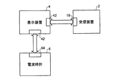
図5は、本発明にかかる医療装置の実施の形態2の概略構成を示す構成図である。図5において、受信装置2および表示装置4の構成は、実施の形態1と同様であり、実施の形態1と異なる点は、表示装置4に時刻が正確な電波時計6が接続されている点である。この表示装置4の時刻設定部DC2は、たとえば定期的にこの電波時計から時刻の取得を行い、この時刻に基づいてタイマDC1の時刻設定を行うように構成されている。次に、電波時計6の動作を、図6のブロック図を用いて説明する。制御部62は、アンテナ61で受信した標準電波をタイムコードに変換する。続いて制御部62は、このタイムコードをデコードして日付および時刻の情報を得る。得た時刻の情報を制御部62に内蔵する図示しないタイマに設定するとともに、表示部63に日時および時刻の情報を表示する。制御部62は、インターフェース部64および表示装置4のインターフェース部42を介して、表示装置4と接続される。表示装置4は、電波時計6と通信を行うことで正確な時間を取得できるようになっている。なお、ここでの通信方式としては、たとえばRS−232Cなどのシリアル通信であるが、本発明はこれに限定されるものではない。
(Embodiment 2)
FIG. 5 is a configuration diagram showing a schematic configuration of the medical device according to the second embodiment of the present invention. In FIG. 5, the configurations of the receiving
次に、図7のフローチャートに基づいて、図5に示した表示装置の時刻設定動作を説明する。図7において、制御部DCは、図示しない通信ケーブルを介して電波時計6との通信を開始する(ステップ201)。そして、時刻調整処理を終了するかどうか判断し(ステップ202)、表示装置4でユーザなどにより終了手順が行われていなければ、時刻取得時間になったかどうか判断する(ステップ203)。
Next, the time setting operation of the display device shown in FIG. 5 will be described based on the flowchart of FIG. In FIG. 7, the control unit DC starts communication with the
ここで、定期的に行われる時刻取得時間になった場合には、電波時計6から現在の時刻を取得して、時刻設定部DC2がこの取得時間に基づいて、タイマDC1の時刻設定を行う(ステップ204)。そして、ステップ202に戻り、表示装置4でユーザなどにより時刻調整処理の終了手順が行われていれば、ステップ206に進んで電波時計6との通信を終了する。
Here, when the time acquisition time that is periodically performed is reached, the current time is acquired from the
以上の処理により、表示装置4のタイマDC1に設定後、実施の形態1と同様に、外部装置2bとの通信を行うことにより、正確な時刻設定が可能となる。また、外部装置2bとの初期化処理中にのみ電波時計6との通信を行い、外部装置2bのタイマC2の時刻設定を行なっても良い。
Through the above processing, after setting the timer DC1 of the display device 4, communication with the
このように、この実施の形態では、表示装置に時刻が正確な電波時計を接続させ、定期的に電波時計の時刻を表示装置が参照して、両タイマの時刻合わせを行うので、受信装置と表示装置の正確な時刻調整が可能となって、検査の時刻情報と画像データに付加された時刻情報との整合性をとって、適切な画像データの選出および表示を行うことができる。 As described above, in this embodiment, a radio timepiece whose time is accurate is connected to the display device, and the display device periodically refers to the time of the radio timepiece to adjust the time of both timers. It is possible to accurately adjust the time of the display device, and it is possible to select and display appropriate image data by matching the time information of the inspection and the time information added to the image data.
なお、この実施の形態では、電波時計を用いて正確な時刻設定を行ったが、本発明はこれに限らず、たとえばSNTP(Simple Network Time Protocol)を用いたサーバーを表示装置に接続させて、時刻の同期をとるように構成することも可能であり、この場合も実施の形態2と同様の効果を奏することができる。また、この医療装置で取得した画像データを、複数のワークステーションからなる端末装置で利用できるようにLANなどのネットワークを構築する場合も、各端末装置がSNTPを用いたサーバーによって時刻の同期をとるように構成すれば、ネットワーク全体で上記効果を奏することができる。 In this embodiment, an accurate time setting is performed using a radio-controlled timepiece. However, the present invention is not limited to this, and for example, a server using SNTP (Simple Network Time Protocol) is connected to a display device, It is also possible to configure to synchronize the time, and in this case, the same effect as in the second embodiment can be obtained. Also, when a network such as a LAN is constructed so that the image data acquired by the medical device can be used by a terminal device composed of a plurality of workstations, the time of each terminal device is synchronized by a server using SNTP. If comprised in this way, the said effect can be show | played by the whole network.
(実施の形態3)
この実施の形態において、実施の形態1と異なる点は、図3に示すように、表示装置4の制御部DCが、タイマDC1に接続される判断手段としての判断部DC3と、取得した画像データのサムネイル画像(縮小画像)を作成する作成処理部DC4とを備える点と、作成処理部DC4によって作成されたサムネイル画像を表示手段としての表示部41に表示させる機能が付加される点である。時刻設定部DC2は、このサムネイル画像の表示を可能にするために、初期設定の際に上述した時刻合わせを行うとともに、検査開始時刻と検査終了時刻の設定を行い、判断部DC3は、この設定された時刻の範囲内に、受信装置2から取り込まれた各画素データに付加された画像取得時間(実施の形態1参照)が入るかどうか判断し、作成処理部DC4は、この判断結果に基づいてサムネイル画像の作成処理を行う。
(Embodiment 3)
In this embodiment, the difference from the first embodiment is that, as shown in FIG. 3, the control unit DC of the display device 4 has a determination unit DC3 as a determination unit connected to the timer DC1, and acquired image data. And a function of displaying the thumbnail image created by the creation processing unit DC4 on the
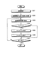
次に、図8のフローチャートに基づいて、図3に示した表示装置のサムネイル画像の作成・表示動作を説明する。なお、この実施の形態では、検査が終了して画像データが表示装置4内に記録されている状態で、各検査を区別するユニークな検査IDを名前とするフォルダに対して検査管理ファイル(患者情報、検査開始時間、検査終了時間などを記録する)および、画像取得時間をファイル名とする画像を保存する場合について説明する。 Next, a thumbnail image creation / display operation of the display device shown in FIG. 3 will be described based on the flowchart of FIG. In this embodiment, in the state where the examination is finished and the image data is recorded in the display device 4, the examination management file (patient (Recording information, inspection start time, inspection end time, etc.) and an image having an image acquisition time as a file name will be described.
図8において、まず検査IDをキーボードなどの情報入力手段から入力して、サムネイル表示対象の検査を指定する(ステップ301)。入力された検査IDを名前とするフォルダから、検査管理ファイルを読み込み検査開始時間Ts、検査終了時間Teを取得する(ステップ302)。次に、画像ファイル名から画像取得時間Tを取得して(ステップ303)、判断部DC3は、画像取得時刻Tが検査開始時刻Tsと検査終了時刻Teの範囲内にあるかどうか判断する(ステップ304)。 In FIG. 8, first, an inspection ID is input from an information input means such as a keyboard, and an inspection to be displayed as a thumbnail is designated (step 301). The inspection management file is read from the folder whose name is the input inspection ID, and the inspection start time Ts and the inspection end time Te are acquired (step 302). Next, the image acquisition time T is acquired from the image file name (step 303), and the determination unit DC3 determines whether the image acquisition time T is within the range between the inspection start time Ts and the inspection end time Te (step 303). 304).
ここで、Ts<T<Teの場合には、条件に適合すると判断して、この判断結果を再生処理部DC4に出力する。作成処理部DC4は、この判断結果から画像データのサムネイル画像を作成して(ステップ305)、表示部41に作成したサムネイル画像を出力し、表示部41による表示を可能にする(ステップ306)。このサムネイル画像の表示が終了した場合、またはステップ304でTs<T<Teの条件に該当しない場合には、全て表示したかどうか判断し(ステップ307)、検査開始時刻Tsと検査終了時刻Teの範囲内の全てのサムネイル画像を表示した場合には、上記動作を終了し、また全て表示していない場合には、ステップ303に戻って、次のファイルの画像取得時刻を取得することで、検査対象の検査開始時刻Tsと検査終了時刻Teの範囲内に取得された画像に対するサムネイル表示を可能にする。
If Ts <T <Te, it is determined that the condition is met, and the determination result is output to the reproduction processing unit DC4. The creation processing unit DC4 creates a thumbnail image of the image data from the determination result (step 305), outputs the created thumbnail image to the
このように、この実施の形態では、検査の開始時刻と終了時刻を設定し、各画像データに付加された画像取得時間がこの設定範囲内のときは適切な画像データと判断してサムネイル画像の表示を可能とする画像(縮小)処理を行うので、正確に時刻調整と併せて、検査の時刻情報と画像データに付加された時刻情報との整合性をとって、さらに適切な画像データの選出および表示を行うことができる。 As described above, in this embodiment, the inspection start time and end time are set, and when the image acquisition time added to each image data is within this setting range, it is determined that the image data is appropriate and the thumbnail image Since the image (reduction) processing that enables display is performed, it is possible to select more appropriate image data by accurately matching the time information of the examination and the time information added to the image data together with the time adjustment. And display.
1 被検体
2 受信装置
2a 受信ジャケット
2b 外部装置
3 カプセル型内視鏡
4 表示装置
5 通信ケーブル
6 電波時計
11 受信回路
12 信号処理回路
13 記憶部
14,41,63 表示部
15 サンプルホールド回路
16 A/D変換部
17 電力供給部
18,42,64 インターフェース部
61 アンテナ
A1〜An 受信用アンテナ
C,DC,62 制御部
C1 選択制御部
C2,DC1 タイマ
C3,DC2 時刻設定部
C4 時刻付加部
CON 接続部
CON1〜CONn コネクタ
DC3 判断部
DC4 作成処理部
SC 切替制御部
SW 切替スイッチ
DESCRIPTION OF
Claims (4)
前記表示装置は、
時刻を計時する第1の計時手段と、
前記計時された時刻情報を送出する送出手段と、
を備え、前記受信装置は、
時刻を計時する第2の計時手段と、
前記送出手段からの時刻情報に基づいて、前記第2の計時手段の時刻設定を行う第2の時刻設定手段と、
を備えることを特徴とする医療装置。 In a medical device comprising a receiving device that receives a wireless video signal transmitted from a moving transmitting device and a display device that displays an image based on the wireless video signal received by the receiving device,
The display device
A first time measuring means for measuring time;
Sending means for sending the timed time information;
The receiving device comprises:
A second time measuring means for measuring time;
Second time setting means for setting the time of the second time measuring means based on time information from the sending means;
A medical device comprising:
さらに備えることを特徴とする請求項1に記載の医療装置。 The display device includes first time setting means for setting time of the first time measuring means based on time information from the outside,
The medical device according to claim 1, further comprising:
前記受信装置は、前記第2の計時手段によって前記被検体内情報の取得時間を設定し、
前記表示装置は、前記被検体内情報に基づくサムネイル画像の表示が可能な表示手段と、
前記第1の計時手段によって前記検査の開始時刻と終了時刻を設定するとともに、前記開始時刻と前記終了時刻と前記受信装置で設定された前記取得時間に基づいて、前記サムネイル画像の表示の有無を判断する判断手段と、
前記判断手段の判断結果に基づいて、前記サムネイル画像を作成する作成手段と、
をさらに備えることを特徴とする請求項1または2に記載の医療装置。 The transmission device wirelessly transmits in-subject information acquired from within the subject to be examined,
The receiving device sets the acquisition time of the in-vivo information by the second time measuring means;
The display device includes display means capable of displaying thumbnail images based on the in-subject information;
The start time and end time of the examination are set by the first time measuring means, and whether or not the thumbnail image is displayed is determined based on the start time, the end time, and the acquisition time set by the receiving device. A judging means for judging;
Creating means for creating the thumbnail image based on the judgment result of the judging means;
The medical device according to claim 1, further comprising:
さらに備えることを特徴とする請求項1〜3のいずれか一つに記載の医療装置。 The receiving device includes time adding means for adding a reception time to the image.
The medical device according to any one of claims 1 to 3, further comprising:
Priority Applications (1)
| Application Number | Priority Date | Filing Date | Title |
|---|---|---|---|
| JP2004121422A JP2005304512A (en) | 2004-04-16 | 2004-04-16 | Medical apparatus |
Applications Claiming Priority (1)
| Application Number | Priority Date | Filing Date | Title |
|---|---|---|---|
| JP2004121422A JP2005304512A (en) | 2004-04-16 | 2004-04-16 | Medical apparatus |
Publications (2)
| Publication Number | Publication Date |
|---|---|
| JP2005304512A true JP2005304512A (en) | 2005-11-04 |
| JP2005304512A5 JP2005304512A5 (en) | 2007-05-10 |
Family
ID=35433972
Family Applications (1)
| Application Number | Title | Priority Date | Filing Date |
|---|---|---|---|
| JP2004121422A Pending JP2005304512A (en) | 2004-04-16 | 2004-04-16 | Medical apparatus |
Country Status (1)
| Country | Link |
|---|---|
| JP (1) | JP2005304512A (en) |
Cited By (5)
| Publication number | Priority date | Publication date | Assignee | Title |
|---|---|---|---|---|
| WO2007061008A1 (en) * | 2005-11-24 | 2007-05-31 | Olympus Medical Systems Corp. | Device for displaying in vivo image, receiving device, and image display system and method using them |
| WO2007074900A1 (en) * | 2005-12-28 | 2007-07-05 | Olympus Medical Systems Corp. | Receiving device, in vivo information acquisition system using the same, and information registration method |
| JP2007325741A (en) * | 2006-06-07 | 2007-12-20 | Olympus Medical Systems Corp | Medical information management equipment and medical information management system |
| WO2008152947A1 (en) * | 2007-06-12 | 2008-12-18 | Olympus Corporation | In-vivo information acquiring device |
| JP2009008529A (en) * | 2007-06-28 | 2009-01-15 | Toshiba Corp | Vibration measuring system |
Citations (2)
| Publication number | Priority date | Publication date | Assignee | Title |
|---|---|---|---|---|
| JPH09127273A (en) * | 1995-11-02 | 1997-05-16 | Yokogawa Electric Corp | Time shift corrector for data collection |
| JP2004041709A (en) * | 2002-05-16 | 2004-02-12 | Olympus Corp | Capsule medical care device |
-
2004
- 2004-04-16 JP JP2004121422A patent/JP2005304512A/en active Pending
Patent Citations (2)
| Publication number | Priority date | Publication date | Assignee | Title |
|---|---|---|---|---|
| JPH09127273A (en) * | 1995-11-02 | 1997-05-16 | Yokogawa Electric Corp | Time shift corrector for data collection |
| JP2004041709A (en) * | 2002-05-16 | 2004-02-12 | Olympus Corp | Capsule medical care device |
Cited By (12)
| Publication number | Priority date | Publication date | Assignee | Title |
|---|---|---|---|---|
| WO2007061008A1 (en) * | 2005-11-24 | 2007-05-31 | Olympus Medical Systems Corp. | Device for displaying in vivo image, receiving device, and image display system and method using them |
| JP2007143648A (en) * | 2005-11-24 | 2007-06-14 | Olympus Medical Systems Corp | In vivo image display device |
| AU2006317028B2 (en) * | 2005-11-24 | 2010-06-17 | Olympus Medical Systems Corp. | Device for displaying in vivo image, receiving device, and image display system and method using them |
| US8175347B2 (en) | 2005-11-24 | 2012-05-08 | Olympus Medical Systems Corp. | In vivo image display apparatus, receiving apparatus, and image display system using same and image display method thereof |
| WO2007074900A1 (en) * | 2005-12-28 | 2007-07-05 | Olympus Medical Systems Corp. | Receiving device, in vivo information acquisition system using the same, and information registration method |
| JP2007175446A (en) * | 2005-12-28 | 2007-07-12 | Olympus Medical Systems Corp | Receiving device and information acquisition system in subject's using the same |
| AU2006330348B2 (en) * | 2005-12-28 | 2010-06-03 | Olympus Medical Systems Corp. | Receiving device, in vivo information acquisition system using the same, and information registration method |
| US8001373B2 (en) | 2005-12-28 | 2011-08-16 | Olympus Medical Systems Corp. | Receiving apparatus and in-vivo information acquiring system employing the same |
| JP2007325741A (en) * | 2006-06-07 | 2007-12-20 | Olympus Medical Systems Corp | Medical information management equipment and medical information management system |
| WO2008152947A1 (en) * | 2007-06-12 | 2008-12-18 | Olympus Corporation | In-vivo information acquiring device |
| JP2008307122A (en) * | 2007-06-12 | 2008-12-25 | Olympus Corp | In vivo information acquisition apparatus |
| JP2009008529A (en) * | 2007-06-28 | 2009-01-15 | Toshiba Corp | Vibration measuring system |
Similar Documents
| Publication | Publication Date | Title |
|---|---|---|
| JP4472585B2 (en) | Transmission device and in-subject information acquisition system | |
| JP4847075B2 (en) | Receiver | |
| JP4823659B2 (en) | In vivo image display device | |
| KR100865208B1 (en) | Receiving device | |
| JP2005304512A (en) | Medical apparatus | |
| JP4406289B2 (en) | Receiver | |
| CN100579441C (en) | Receiving apparatus and receiving system | |
| JP2006140642A (en) | Image sensing device | |
| WO2005107572A1 (en) | Device for introduction into subject | |
| JP4663279B2 (en) | Reception device, medical device, and identification information generation registration method | |
| US20070081077A1 (en) | Receiver for subject insertable device | |
| JP4009610B2 (en) | Receiver | |
| JP4418327B2 (en) | Receiving device and medical device | |
| JP2005312769A (en) | Receiver and medical apparatus | |
| JP2006155242A (en) | Image recording device, image filing device, image filing system and image filing method | |
| JP2007082780A (en) | Receiver | |
| JP4892065B2 (en) | Receiver and in-subject information acquisition system | |
| JP2006006487A (en) | Receiver | |
| JP2005319095A (en) | Receiver | |
| JP2005223427A (en) | Receiver | |
| JP2006320649A (en) | Receiving device and receiving system | |
| JP2006141898A (en) | Image display system | |
| JP2006075366A (en) | Receiver and transmitter | |
| JP2008252933A (en) | Imaging apparatus |
Legal Events
| Date | Code | Title | Description |
|---|---|---|---|
| A521 | Written amendment |
Free format text: JAPANESE INTERMEDIATE CODE: A523 Effective date: 20070313 |
|
| A621 | Written request for application examination |
Free format text: JAPANESE INTERMEDIATE CODE: A621 Effective date: 20070313 |
|
| A977 | Report on retrieval |
Free format text: JAPANESE INTERMEDIATE CODE: A971007 Effective date: 20100226 |
|
| A131 | Notification of reasons for refusal |
Free format text: JAPANESE INTERMEDIATE CODE: A131 Effective date: 20100615 |
|
| A02 | Decision of refusal |
Free format text: JAPANESE INTERMEDIATE CODE: A02 Effective date: 20101019 |