JP2005299920A - Clutch device - Google Patents

Clutch device Download PDF

Info

Publication number
JP2005299920A
JP2005299920A JP2004309823A JP2004309823A JP2005299920A JP 2005299920 A JP2005299920 A JP 2005299920A JP 2004309823 A JP2004309823 A JP 2004309823A JP 2004309823 A JP2004309823 A JP 2004309823A JP 2005299920 A JP2005299920 A JP 2005299920A
Authority
JP
Japan
Prior art keywords
clutch
piston
chamber
cancel plate
cancel
Prior art date
Legal status (The legal status is an assumption and is not a legal conclusion. Google has not performed a legal analysis and makes no representation as to the accuracy of the status listed.)
Pending
Application number
JP2004309823A
Other languages
Japanese (ja)
Inventor
Takashi Kuwabara
貴史 桑原
Takatsugu Ibaraki
隆次 茨木
Toshiya Yamashita
俊哉 山下
Michio Yoshida
倫生 吉田
朋亮 ▲柳▼田
Tomoaki Yanagida
Current Assignee (The listed assignees may be inaccurate. Google has not performed a legal analysis and makes no representation or warranty as to the accuracy of the list.)
Toyota Motor Corp
Original Assignee
Toyota Motor Corp
Priority date (The priority date is an assumption and is not a legal conclusion. Google has not performed a legal analysis and makes no representation as to the accuracy of the date listed.)
Filing date
Publication date
Application filed by Toyota Motor Corp filed Critical Toyota Motor Corp
Priority to JP2004309823A priority Critical patent/JP2005299920A/en
Publication of JP2005299920A publication Critical patent/JP2005299920A/en
Pending legal-status Critical Current

Links

Images

Landscapes

  • Hydraulic Clutches, Magnetic Clutches, Fluid Clutches, And Fluid Joints (AREA)

Abstract

<P>PROBLEM TO BE SOLVED: To provide a clutch device to effect engagement of a clutch rapidly with excellent responsiveness. <P>SOLUTION: The clutch device 50 is provided with a clutch drum 51; and a piston 52 movably situated in the clutch drum 51, and working oil is fed to an oil chamber 53 between the clutch drum 51 and the piston 52, when the clutch is engaged, to move the piston 52. A cancel plate 54 to define a centrifugal oil pressure cancellation chamber 55 filled with the working oil is situated on the opposite side to the oil chamber 53 with the piston 52 positioned therebetween. When the clutch is engaged, the working oil in the centrifugal oil pressure cancellation chamber 55 is discharged from the outer peripheral side of the centrifugal oil pressure cancellation chamber 55 to the outside. <P>COPYRIGHT: (C)2006,JPO&NCIPI

Description

本発明は、クラッチドラムとピストンとを備えたクラッチ装置に関し、特に、クラッチドラムとピストンとの間の油室内に生じる遠心油圧を相殺することができるクラッチ装置に関する。   The present invention relates to a clutch device including a clutch drum and a piston, and more particularly to a clutch device capable of canceling centrifugal hydraulic pressure generated in an oil chamber between the clutch drum and the piston.

従来から、クラッチドラムとピストンとの間の油室内に生じる遠心油圧を相殺するための遠心油圧キャンセル室を備えたクラッチ装置が知られている(例えば、特許文献1参照。)。このクラッチ装置では、ピストンを挟んで上記油室の反対側にキャンセルプレートが配置され、このキャンセルプレートとピストンとの間に作動油で満たされる遠心油圧キャンセル室が画成される。そして、クラッチ係合の際には、ピストンがキャンセルプレートに向けて移動するように上記油室内に作動油が供給される。この場合、ピストンがキャンセルプレートに接近することにより遠心油圧キャンセル室の容積が減少するので、遠心油圧キャンセル室内の作動油を外部に排出する必要が生じる。このため、特許文献1に記載のクラッチ装置では、クラッチ係合の際、キャンセルプレートの内周部とキャンセルプレートが固定される回転部材とに形成された切欠きから、遠心油圧キャンセル室内の作動油が外部に排出される。   2. Description of the Related Art Conventionally, a clutch device having a centrifugal oil pressure cancellation chamber for canceling centrifugal oil pressure generated in an oil chamber between a clutch drum and a piston is known (see, for example, Patent Document 1). In this clutch device, a cancel plate is disposed on the opposite side of the oil chamber across the piston, and a centrifugal hydraulic pressure cancel chamber filled with hydraulic oil is defined between the cancel plate and the piston. When the clutch is engaged, hydraulic oil is supplied into the oil chamber so that the piston moves toward the cancel plate. In this case, since the volume of the centrifugal oil pressure cancellation chamber decreases as the piston approaches the cancel plate, the hydraulic oil in the centrifugal oil pressure cancellation chamber needs to be discharged to the outside. For this reason, in the clutch device described in Patent Document 1, when the clutch is engaged, the hydraulic oil in the centrifugal hydraulic pressure cancellation chamber is removed from the notch formed in the inner peripheral portion of the cancellation plate and the rotating member to which the cancellation plate is fixed. Is discharged to the outside.

特開2001−41261号公報JP 2001-41261 A

しかしながら、上述のように構成される従来のクラッチ装置では、クラッチ係合のためにピストンをキャンセルプレートに向けて移動させ始めてからクラッチ係合が完了するまでのタイムラグが大きく、特に、作動油の流動性が悪化する周囲温度が低い場合、このようなタイムラグが顕著となるおそれがあった。   However, in the conventional clutch device configured as described above, the time lag from when the piston starts to move toward the cancel plate for clutch engagement until the clutch engagement is completed is large. When the ambient temperature at which the property deteriorates is low, such a time lag may become remarkable.

そこで、本発明は、クラッチ係合を速やかに応答性よく実行することができるクラッチ装置の提供を目的とする。   Therefore, an object of the present invention is to provide a clutch device that can execute clutch engagement quickly and with high responsiveness.

本発明によるクラッチ装置は、クラッチドラムと、クラッチドラム内に移動自在に配置されるピストンとを備え、クラッチ係合の際にクラッチドラムとピストンとの間の油室に作動油を供給してピストンを移動させるクラッチ装置において、ピストンを挟んで油室の反対側に、作動油で満たされる遠心油圧キャンセル室を画成するキャンセルプレートを備え、クラッチ係合の際に、遠心油圧キャンセル室内の作動油が該遠心油圧キャンセル室の外周側から外部に排出されることを特徴とする。   A clutch device according to the present invention includes a clutch drum and a piston movably disposed in the clutch drum, and supplies hydraulic oil to an oil chamber between the clutch drum and the piston when the clutch is engaged. In the clutch device for moving the piston, a cancel plate defining a centrifugal hydraulic pressure cancellation chamber filled with hydraulic oil is provided on the opposite side of the oil chamber across the piston, and the hydraulic oil in the centrifugal hydraulic pressure cancellation chamber is engaged when the clutch is engaged. Is discharged to the outside from the outer peripheral side of the centrifugal hydraulic pressure canceling chamber.

一般に、遠心油圧キャンセル室内においても、クラッチドラムとピストンとの間の油室と同様に遠心油圧が発生することから、遠心油圧キャンセル室内の作動油の圧力は、キャンセル室内の外周側ほど高まることになる。従って、このクラッチ装置のように、クラッチ係合の際に遠心油圧キャンセル室内の作動油がキャンセル室の外周側から外部に排出されるようにしておけば、ピストンをキャンセルプレートに向けて移動させ始めると、ピストンの移動量に応じた量の作動油が遠心油圧キャンセル室から外部へと速やかに流出することになる。この結果、このクラッチ装置では、周囲温度が低く作動油の粘性が高いような場合であっても、クラッチ係合を開始してから完了するまでのタイムラグを良好に低減可能となり、クラッチ係合を速やかに応答性よく実行することができる。   In general, the centrifugal oil pressure is generated in the centrifugal oil pressure cancellation chamber as well as the oil chamber between the clutch drum and the piston. Therefore, the hydraulic oil pressure in the centrifugal oil pressure cancellation chamber increases toward the outer peripheral side of the cancellation chamber. Become. Therefore, if the hydraulic oil in the centrifugal oil pressure cancellation chamber is discharged from the outer peripheral side of the cancellation chamber to the outside when the clutch is engaged as in this clutch device, the piston starts to move toward the cancellation plate. As a result, the amount of hydraulic oil corresponding to the amount of movement of the piston quickly flows out from the centrifugal hydraulic pressure cancel chamber to the outside. As a result, in this clutch device, even when the ambient temperature is low and the viscosity of the hydraulic fluid is high, the time lag from the start to the completion of clutch engagement can be reduced well, and the clutch engagement is prevented. It can be executed quickly and with good responsiveness.

この場合、本発明によるクラッチ装置では、クラッチ係合のためにピストンをキャンセルプレートに向けて移動させると、ピストンの外周部とキャンセルプレートの外周部との間に流路が形成されると好ましい。   In this case, in the clutch device according to the present invention, it is preferable that when the piston is moved toward the cancel plate for clutch engagement, a flow path is formed between the outer peripheral portion of the piston and the outer peripheral portion of the cancel plate.

また、ピストンは、キャンセルプレートの外周部と当接可能な段部を有し、当該段部は、クラッチ解除の際にキャンセルプレートと協働して遠心油圧キャンセル室からの作動油の流出を規制すると好ましい。このような構成によれば、クラッチ解除の際には、遠心油圧キャンセル室からの作動油の流出を確実に阻止可能となり、クラッチ係合の際には、遠心油圧キャンセル室内の作動油をキャンセル室の外周側から外部へと速やかに流出させることができる。そして、かかる構成は、低コストかつ容易に実現することができる。   In addition, the piston has a step portion that can come into contact with the outer peripheral portion of the cancel plate, and the step portion cooperates with the cancel plate when releasing the clutch to regulate the outflow of hydraulic oil from the centrifugal hydraulic pressure cancel chamber. It is preferable. According to such a configuration, when the clutch is released, it is possible to reliably prevent the hydraulic oil from flowing out from the centrifugal hydraulic pressure cancellation chamber. When the clutch is engaged, the hydraulic oil in the centrifugal hydraulic pressure cancellation chamber is removed. Can be quickly discharged from the outer peripheral side to the outside. Such a configuration can be easily realized at low cost.

更に、ピストンの外周部およびキャンセルプレートの外周部のそれぞれには孔部が形成され、クラッチ係合のためにピストンを移動させると、ピストンの孔部とキャンセルプレートの孔部とが互いに連通してもよい。このような構成によっても、クラッチ解除の際には、遠心油圧キャンセル室からの作動油の流出を確実に阻止可能となり、クラッチ係合の際には、遠心油圧キャンセル室内の作動油をキャンセル室の外周側から外部へと速やかに流出させることができる。そして、かかる構成も、低コストかつ容易に実現することができる。   Furthermore, a hole is formed in each of the outer periphery of the piston and the outer periphery of the cancel plate. When the piston is moved for clutch engagement, the piston hole and the cancel plate hole communicate with each other. Also good. Even with such a configuration, when the clutch is released, it is possible to reliably prevent the hydraulic oil from flowing out of the centrifugal hydraulic pressure cancellation chamber. When the clutch is engaged, the hydraulic oil in the centrifugal hydraulic pressure cancellation chamber is removed from the cancellation chamber. It can quickly flow out from the outer peripheral side to the outside. Such a configuration can also be easily realized at low cost.

また、本発明によるクラッチ装置は、クラッチ係合が完了する際に遠心油圧キャンセル室からの作動油の排出が規制されると好ましい。このような構成のもとでは、クラッチ係合が完了した際(実質的に完了した際)に、遠心油圧キャンセル室内に作動流体を残留させることが可能となる。これにより、クラッチ解除に際して、遠心油圧キャンセル室内に残留した作動流体からピストンに対して遠心油圧による反力を作用させることができるので、クラッチ解除を速やかに応答性よく良好に実行可能となる。   In the clutch device according to the present invention, it is preferable that the discharge of the hydraulic oil from the centrifugal oil pressure cancellation chamber is restricted when the clutch engagement is completed. Under such a configuration, when the clutch engagement is completed (substantially completed), the working fluid can be left in the centrifugal hydraulic pressure cancellation chamber. Thereby, when releasing the clutch, a reaction force by the centrifugal oil pressure can be applied to the piston from the working fluid remaining in the centrifugal oil pressure canceling chamber, so that the clutch can be released quickly and satisfactorily with good responsiveness.

この場合、クラッチ係合のためにピストンをキャンセルプレートに向けて移動させると、ピストンの外周部とキャンセルプレートの外周部との間に流路が形成され、ピストンをキャンセルプレートに向けて更に移動させると、クラッチ係合の完了前に流路が閉鎖されると好ましい。また、ピストンは、キャンセルプレートの外周部と当接可能な第1の段部と、この第1の段部よりも内側に形成されており、キャンセルプレートの外周部と当接可能な第2の段部とを含み、第1の段部と第2の段部との間では、キャンセルプレートの外周部とピストンとの間に隙間が形成されると好ましい。   In this case, when the piston is moved toward the cancel plate for clutch engagement, a flow path is formed between the outer periphery of the piston and the outer periphery of the cancel plate, and the piston is further moved toward the cancel plate. It is preferable that the flow path is closed before the clutch engagement is completed. The piston is formed on the inner side of the first step portion that can come into contact with the outer peripheral portion of the cancel plate and the second step portion that can come into contact with the outer peripheral portion of the cancel plate. Preferably, a gap is formed between the first step portion and the second step portion between the outer peripheral portion of the cancel plate and the piston.

本発明によれば、クラッチ係合を速やかに応答性よく実行することができるクラッチ装置の実現が可能となる。   According to the present invention, it is possible to realize a clutch device that can execute clutch engagement quickly and with high responsiveness.

以下、図面を参照しながら、本発明を実施するための最良の形態について詳細に説明する。   Hereinafter, the best mode for carrying out the present invention will be described in detail with reference to the drawings.

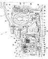
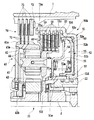
図1は、本発明によるクラッチ装置を含む車両用トランスアクスルの一部を示す拡大断面図である。同図に示されるトランスアクスル1は、図示されないエンジンの側方に配置され、当該エンジンのクランクシャフトと連結される。トランスアクスル1は、トランスアクスルハウジング2やトランスアクスルケース3を含む。トランスアクスルハウジング2の内部には、トルクコンバータ10が配置されており、トランスアクスルケースの内部には、本発明によるクラッチ装置50を含む前後進切り換え機構(動力伝達装置)30やベルト式無段変速機(CVT)5、更には、図示されない最終減速機(差動装置)等が配置される。   FIG. 1 is an enlarged sectional view showing a part of a vehicle transaxle including a clutch device according to the present invention. A transaxle 1 shown in the figure is disposed on the side of an engine (not shown) and is connected to a crankshaft of the engine. The transaxle 1 includes a transaxle housing 2 and a transaxle case 3. A torque converter 10 is disposed inside the transaxle housing 2, and a forward / reverse switching mechanism (power transmission device) 30 including a clutch device 50 according to the present invention and a belt-type continuously variable transmission are arranged inside the transaxle case. A machine (CVT) 5 and a final reduction gear (differential device) (not shown) are arranged.

トルクコンバータ10は、図示されないドライブプレートを介してエンジンのクランクシャフトに固定されるフロントカバー11を有する。フロントカバー11には、図1に示されるように、ポンプインペラ12が取り付けられている。また、トルクコンバータ10は、ポンプインペラ12と対向する状態で回転可能なタービンランナ13を含む。タービンランナ13は、タービンハブ14を介してクランクシャフトと概ね同軸に延びる入力シャフトSに固定されている。更に、ポンプインペラ12およびタービンランナ13の内側にはステータ15が配置されている。ステータ15には、その回転方向を一方向のみに設定するワンウェイクラッチ16を介して中空軸17が固定されており、上述の入力シャフトSは、この中空軸17の内部に挿通されている。このように構成されるトルクコンバータ10は、ポンプインペラ12とタービンランナ13との回転速度差が大きい時には、トルク増幅機として作動し、両者の回転速度差が小さくなると、流体継手として作動する。   The torque converter 10 includes a front cover 11 that is fixed to an engine crankshaft via a drive plate (not shown). A pump impeller 12 is attached to the front cover 11 as shown in FIG. The torque converter 10 includes a turbine runner 13 that can rotate in a state of facing the pump impeller 12. The turbine runner 13 is fixed to an input shaft S that extends substantially coaxially with the crankshaft via a turbine hub 14. Further, a stator 15 is disposed inside the pump impeller 12 and the turbine runner 13. A hollow shaft 17 is fixed to the stator 15 via a one-way clutch 16 that sets the rotation direction to only one direction, and the above-described input shaft S is inserted into the hollow shaft 17. The torque converter 10 configured as described above operates as a torque amplifier when the rotational speed difference between the pump impeller 12 and the turbine runner 13 is large, and operates as a fluid coupling when the rotational speed difference between the two becomes small.

そして、入力シャフトSのフロントカバー11側の端部には、タービンハブ14に連結されたダンパユニット18と、ロックアップピストン190や摩擦板191を含み、フロントカバー11とダンパユニット18(タービンハブ14)とを連結するロックアップクラッチ機構19が配置されている。ロックアップクラッチ機構19は、車両の発進後、車速が所定速度に達すると作動され、それにより、エンジンからフロントカバー11に伝えられた動力が入力シャフトSに機械的かつ直接に伝達されるようになる。また、フロントカバー11から入力シャフトSに伝達されるトルクの変動は、ダンパユニット18によって吸収される。   The end of the input shaft S on the front cover 11 side includes a damper unit 18 coupled to the turbine hub 14, a lock-up piston 190 and a friction plate 191, and the front cover 11 and the damper unit 18 (the turbine hub 14 ) Is arranged. The lock-up clutch mechanism 19 is activated when the vehicle speed reaches a predetermined speed after the vehicle starts, so that the power transmitted from the engine to the front cover 11 is mechanically and directly transmitted to the input shaft S. Become. Further, the fluctuation of the torque transmitted from the front cover 11 to the input shaft S is absorbed by the damper unit 18.

図1に示されるように、本実施形態のロックアップクラッチ機構19では、入力シャフトSのフロントカバー11側の先端部が縮径されており、入力シャフトSの縮径部Sdによってロックアップピストン190の内周側端部190aが支持される。そして、ロックアップピストン190の内周側端部190aは、タービンハブ14に向けて延在しており、入力シャフトSの大径部の端面Seによって位置決めされる。これにより、ロックアップクラッチ機構19では、ロックアップ時にタービンハブ14の前後の差圧を無くすことができるので、フロントカバー11とロックアップピストン190との間にスラスト軸受を配置する必要がない。また、本実施形態では、図1からわかるように、入力シャフトSを縮径させた分だけ、ロックアップピストンの受圧面積が大きくなるので、その分だけトルク容量を増大化させることができる。なお、図1の例では、ロックアップクラッチ機構19は、単板式のクラッチ機構として構成されているが、これに限られるものではなく、ロックアップクラッチ機構19は、多板クラッチ機構として構成されてもよい。   As shown in FIG. 1, in the lockup clutch mechanism 19 of this embodiment, the front end portion of the input shaft S on the front cover 11 side is reduced in diameter, and the lockup piston 190 is reduced by the reduced diameter portion Sd of the input shaft S. The inner peripheral side end 190a is supported. The inner peripheral end 190a of the lockup piston 190 extends toward the turbine hub 14 and is positioned by the end surface Se of the large diameter portion of the input shaft S. Thereby, in the lockup clutch mechanism 19, the differential pressure before and after the turbine hub 14 can be eliminated at the time of lockup, so that it is not necessary to arrange a thrust bearing between the front cover 11 and the lockup piston 190. Further, in this embodiment, as can be seen from FIG. 1, the pressure receiving area of the lockup piston is increased by the diameter of the input shaft S, so that the torque capacity can be increased by that amount. In the example of FIG. 1, the lock-up clutch mechanism 19 is configured as a single-plate clutch mechanism, but is not limited thereto, and the lock-up clutch mechanism 19 is configured as a multi-plate clutch mechanism. Also good.

また、図2に示されるように、入力シャフトSのフロントカバー11側の先端部は、縮径されなくてもよい。図2に示されるトルクコンバータ10Aのロックアップクラッチ機構19Aでは、ロックアップピストン190の内周側端部190aが入力シャフトSの縮径されていない先端部によって支持され、ロックアップピストン190は、タービンハブ14のフロントカバー11側に形成された凹部14aによって位置決めされる。かかる構成を採用しても、ロックアップ時に、タービンハブ14の前後の差圧を無くすことが可能となるので、フロントカバー11とロックアップピストン190との間にスラスト軸受を配置する必要がなくなる。   Further, as shown in FIG. 2, the front end portion of the input shaft S on the front cover 11 side may not be reduced in diameter. In the lockup clutch mechanism 19A of the torque converter 10A shown in FIG. 2, the inner peripheral side end portion 190a of the lockup piston 190 is supported by the tip portion of the input shaft S which is not reduced in diameter. The hub 14 is positioned by a recess 14a formed on the front cover 11 side. Even if such a configuration is adopted, it is possible to eliminate the differential pressure across the turbine hub 14 during lockup, so that it is not necessary to dispose a thrust bearing between the front cover 11 and the lockup piston 190.

図1に示されるように、トルクコンバータ10と前後進切り換え機構30との間には、オイルポンプ20が配置されている。オイルポンプ20は、ポンプボディー21、ポンプカバー22、ドライブギヤ23およびドリブンギヤ24等を含む。ドライブギヤ23は、ハブ25を介してポンプインペラ12と接続されると共に、中空軸17に対してスプライン嵌合されている。また、ポンプボディー21とポンプカバー22とは、互いにボルト結合された上でトランスアクスルケース3側に固定されている。従って、エンジンの動力は、ポンプインペラ12を介してドライブギヤ23に伝達されることになり、これにより、オイルポンプ20が駆動される。   As shown in FIG. 1, an oil pump 20 is disposed between the torque converter 10 and the forward / reverse switching mechanism 30. The oil pump 20 includes a pump body 21, a pump cover 22, a drive gear 23, a driven gear 24, and the like. The drive gear 23 is connected to the pump impeller 12 via the hub 25 and is splined to the hollow shaft 17. Further, the pump body 21 and the pump cover 22 are fixed to the transaxle case 3 side by being bolted to each other. Accordingly, the engine power is transmitted to the drive gear 23 via the pump impeller 12, thereby driving the oil pump 20.

一方、前後進切り換え機構30は、入力シャフトSと変速機5との間の動力伝達経路上に設けられており、遊星歯車機構40と、いわゆるフォワードクラッチとして用いられる本発明によるクラッチ装置50と、リバースブレーキ70とを含む。遊星歯車機構40は、リングギヤ41、入力シャフトSに取り付けられたサンギヤ42、リングギヤ41またはサンギヤ42と噛合う複数のピニオンギヤ44、並びにピニオンギヤ44をサンギヤ42の周囲で一体的に公転可能な状態に保持するキャリヤ45を含む。リングギヤ41、サンギヤ42、およびピニオンギヤ44としては、ギヤノイズを低減するためにヘリカルギヤが採用される。   On the other hand, the forward / reverse switching mechanism 30 is provided on a power transmission path between the input shaft S and the transmission 5, and includes a planetary gear mechanism 40 and a clutch device 50 according to the present invention used as a so-called forward clutch, And reverse brake 70. The planetary gear mechanism 40 holds the ring gear 41, a sun gear 42 attached to the input shaft S, a plurality of pinion gears 44 that mesh with the ring gear 41 or the sun gear 42, and the pinion gear 44 so as to be integrally revolved around the sun gear 42. Carrier 45. As the ring gear 41, the sun gear 42, and the pinion gear 44, helical gears are employed to reduce gear noise.

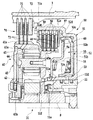
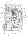
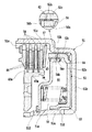
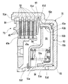
クラッチ装置50は、遊星歯車機構40を介した入力シャフトSと変速機5のプライマリシャフト6との動力伝達経路を接続・遮断するものである。図1および図3に示されるように、クラッチ装置50は、ポンプカバー22等を介して入力シャフトSに連結されたクラッチドラム51を含む。クラッチドラム51は、ポンプカバー22に対して入力シャフトSの軸方向に嵌め込まれる基部51aと、基部51aから入力シャフトSの径方向に延出された径方向端部51bと、径方向端部51bの外周部から変速機5に向けて入力シャフトSと概ね平行に延出された外側筒状部51cとを有する。   The clutch device 50 connects / disconnects the power transmission path between the input shaft S and the primary shaft 6 of the transmission 5 via the planetary gear mechanism 40. As shown in FIGS. 1 and 3, the clutch device 50 includes a clutch drum 51 coupled to the input shaft S via the pump cover 22 and the like. The clutch drum 51 includes a base 51a fitted in the pump cover 22 in the axial direction of the input shaft S, a radial end 51b extending from the base 51a in the radial direction of the input shaft S, and a radial end 51b. And an outer cylindrical portion 51c extending substantially in parallel with the input shaft S from the outer peripheral portion toward the transmission 5.

クラッチドラム51の内部には、ピストン52が摺動自在に配置されている。ピストン52は、クラッチドラム51の基部51aに対して入力シャフトSの軸方向に摺動自在となるように嵌め込まれる基部52aと、基部52aから入力シャフトSの径方向に延出された径方向端部52bと、径方向端部52bの外周部から変速機5に向けて入力シャフトSと概ね平行に延出された外側筒状部(ピストンの外周部)52cとを有する。クラッチドラム51の基部51aとピストン52の基部52aとの間およびクラッチドラム51の外側筒状部51cとピストン52の外側筒状部52cとの間は、油密状態に保たれる。そして、クラッチドラム51とピストン52との間には油室53が画成され、クラッチドラム51の基部51aには、油室53に作動油を供給するための孔部51dが形成されている。   A piston 52 is slidably disposed inside the clutch drum 51. The piston 52 includes a base portion 52a fitted so as to be slidable in the axial direction of the input shaft S with respect to the base portion 51a of the clutch drum 51, and a radial end extending from the base portion 52a in the radial direction of the input shaft S. A portion 52b and an outer cylindrical portion (outer peripheral portion of the piston) 52c extending substantially parallel to the input shaft S from the outer peripheral portion of the radial end portion 52b toward the transmission 5. The space between the base portion 51a of the clutch drum 51 and the base portion 52a of the piston 52 and the space between the outer cylindrical portion 51c of the clutch drum 51 and the outer cylindrical portion 52c of the piston 52 are kept in an oil-tight state. An oil chamber 53 is defined between the clutch drum 51 and the piston 52, and a hole 51 d for supplying hydraulic oil to the oil chamber 53 is formed in the base 51 a of the clutch drum 51.

更に、クラッチドラム51の基部51aには、ピストン52を挟んで油室53の反対側に位置するようにキャンセルプレート54が固定されている。キャンセルプレート54の外周端部は、クラッチドラム51の外側筒状部51cの内面付近に達しており、キャンセルプレート54は、ピストン52の背面と協働して遠心油圧キャンセル室55を画成する。クラッチドラム51の基部51aには、遠心油圧キャンセル室55に作動油を供給するための孔部51eが形成されており、遠心油圧キャンセル室55は基本的に作動油で満たされる。また、ピストン52(径方向端部52b)の背面とキャンセルプレート54との間には、リターンスプリング56が配置されている。リターンスプリング56は、ピストン52をクラッチドラム51の径方向端部51bに向けて付勢する。   Further, a cancel plate 54 is fixed to the base 51 a of the clutch drum 51 so as to be positioned on the opposite side of the oil chamber 53 with the piston 52 interposed therebetween. The outer peripheral end portion of the cancel plate 54 reaches the vicinity of the inner surface of the outer cylindrical portion 51 c of the clutch drum 51, and the cancel plate 54 cooperates with the back surface of the piston 52 to define a centrifugal hydraulic pressure cancel chamber 55. The base 51a of the clutch drum 51 is formed with a hole 51e for supplying hydraulic oil to the centrifugal hydraulic pressure cancellation chamber 55, and the centrifugal hydraulic pressure cancellation chamber 55 is basically filled with hydraulic oil. A return spring 56 is disposed between the back surface of the piston 52 (radial end 52b) and the cancel plate 54. The return spring 56 biases the piston 52 toward the radial end 51 b of the clutch drum 51.

そして、クラッチドラム51の外側筒状部51cの内面には、入力シャフトSと平行に延びる複数のスプライン51sが所定間隔をおいて配設されており、これらのスプライン51sには、受圧板57と複数の摩擦板58とが摺動自在に嵌め込まれている。受圧板57と各摩擦板58とは、クラッチドラム51に対して入力シャフトSの軸方向に摺動自在である一方、入力シャフトSの周方向においてクラッチドラム51と一体化されている。受圧板57は、ピストン52の外側筒状部52cの遊端部と接触できるように、最もピストン52に近接して配置されている。また、最も変速機5側の摩擦板58は、スナップリング59によって軸方向に位置決めされている。   A plurality of splines 51s extending in parallel with the input shaft S are arranged at predetermined intervals on the inner surface of the outer cylindrical portion 51c of the clutch drum 51. The splines 51s are connected to the pressure receiving plate 57 and the spline 51s. A plurality of friction plates 58 are slidably fitted. The pressure receiving plate 57 and the friction plates 58 are slidable in the axial direction of the input shaft S with respect to the clutch drum 51, and are integrated with the clutch drum 51 in the circumferential direction of the input shaft S. The pressure receiving plate 57 is disposed closest to the piston 52 so as to be in contact with the free end portion of the outer cylindrical portion 52 c of the piston 52. Further, the friction plate 58 closest to the transmission 5 is positioned in the axial direction by a snap ring 59.

図3に示されるように、複数のピニオンギヤ44を一体的に保持するキャリヤ45は、クラッチドラム51に向けて延びる筒状部45aを有しており、この筒状部45aの外周面にも入力シャフトSと平行に延びる複数のスプライン45sが所定間隔をおいて配設されている。これらのスプライン45sには、複数の摩擦板46が摺動自在に嵌め込まれている。各摩擦板46は、クラッチドラム51の互いに隣り合う摩擦板58同士の間に配置されており、筒状部45aに対して入力シャフトSの軸方向に摺動自在である一方、入力シャフトSの周方向において筒状部45aと一体化されている。また、キャリヤ45は、変速機5に向けて延びる連結部45bを有しており、この連結部45bは、プライマシャフト6に連結(スプライン嵌合)されている。   As shown in FIG. 3, the carrier 45 that integrally holds the plurality of pinion gears 44 has a cylindrical portion 45 a that extends toward the clutch drum 51, and the outer peripheral surface of the cylindrical portion 45 a is also input. A plurality of splines 45s extending in parallel with the shaft S are arranged at a predetermined interval. A plurality of friction plates 46 are slidably fitted in these splines 45s. Each friction plate 46 is disposed between adjacent friction plates 58 of the clutch drum 51, and is slidable in the axial direction of the input shaft S with respect to the cylindrical portion 45a. It is integrated with the cylindrical portion 45a in the circumferential direction. The carrier 45 has a connecting portion 45 b extending toward the transmission 5, and the connecting portion 45 b is connected to the primer shaft 6 (spline fitting).

リバースブレーキ70は、リングギヤ41の回転を許容または規制することにより、プライマリシャフト6の回転方向を制御するものである。すなわち、リバースブレーキ70は、入力シャフトSと平行に延びる複数のスプライン70sを有する。これら複数のスプライン70sは、リングギヤ41を囲むようにトランスアクスルケース3の内面に所定間隔をおいて配設されており、これらのスプライン70sには、複数の摩擦板71が摺動自在に嵌め込まれている。各摩擦板71は、トランスアクスルケース3に対して入力シャフトSの軸方向に摺動自在である一方、入力シャフトSの周方向においてトランスアクスルケース3と一体化されている。また、最もクラッチドラム51側の摩擦板71は、スナップリング72によって軸方向に位置決めされる。   The reverse brake 70 controls the rotation direction of the primary shaft 6 by allowing or restricting the rotation of the ring gear 41. That is, the reverse brake 70 has a plurality of splines 70s extending in parallel with the input shaft S. The plurality of splines 70s are arranged at predetermined intervals on the inner surface of the transaxle case 3 so as to surround the ring gear 41, and a plurality of friction plates 71 are slidably fitted into these splines 70s. ing. Each friction plate 71 is slidable in the axial direction of the input shaft S with respect to the transaxle case 3, and is integrated with the transaxle case 3 in the circumferential direction of the input shaft S. Further, the friction plate 71 closest to the clutch drum 51 is positioned in the axial direction by the snap ring 72.

そして、リングギヤ41の外周面にも、入力シャフトSと平行に延びる複数のスプライン41sが所定間隔をおいて配設されている。これらのスプライン41sには、複数の摩擦板73が摺動自在に嵌め込まれている。各摩擦板73は、トランスアクスルケース3側の摩擦板71同士の間に配置されており、リングギヤ41に対して入力シャフトSの軸方向に摺動自在である一方、入力シャフトSの周方向においてリングギヤ41と一体化されている。   A plurality of splines 41 s extending in parallel with the input shaft S are also arranged on the outer peripheral surface of the ring gear 41 at a predetermined interval. A plurality of friction plates 73 are slidably fitted in these splines 41s. Each friction plate 73 is disposed between the friction plates 71 on the transaxle case 3 side, and is slidable in the axial direction of the input shaft S with respect to the ring gear 41, while in the circumferential direction of the input shaft S. It is integrated with the ring gear 41.

更に、トランスアクスルケース3の内部には、ブレーキピストン74が摺動自在に配置されており、ブレーキピストン74の背後には、油室75が形成されている(図1参照)。ブレーキピストン74には、リターンスプリング76を介してリテーナ77が接続されている。リテーナ77は、トランスアクスルケース3の各スプライン70sに嵌め込まれており、最も変速機5側の摩擦板71と当接可能である。これらのブレーキピストン74、油室75、リターンスプリング76およびリテーナ77は、リバースブレーキ70の油圧アクチュエータを構成する。   Further, a brake piston 74 is slidably disposed inside the transaxle case 3, and an oil chamber 75 is formed behind the brake piston 74 (see FIG. 1). A retainer 77 is connected to the brake piston 74 via a return spring 76. The retainer 77 is fitted in each spline 70 s of the transaxle case 3 and can contact the friction plate 71 closest to the transmission 5. The brake piston 74, the oil chamber 75, the return spring 76 and the retainer 77 constitute a hydraulic actuator for the reverse brake 70.

さて、上述のように構成されるトランスアクスル1では、ユーザによって変速機5がパーキングあるいはニュートラルレンジからドライブレンジに設定されると、孔部51dを介してクラッチドラム51とピストン52との間の油室53に作動油が供給され、リターンスプリング56の付勢力に抗してピストン52がキャンセルプレート54(変速機5)に向けて移動し、ピストン52の外側筒状部52cの遊端部が受圧板57を押圧するようになる。これにより、クラッチドラム51側の摩擦板58と、キャリヤ45(筒状部45a)側の摩擦板46とが摩擦接触(クラッチ係合)し、クラッチドラム51と、プライマリシャフト6と結合したキャリヤ45とが連結されることになる。この結果、クラッチ装置50によりクラッチ係合が実行されると、エンジンからの駆動力が同じ回転方向でキャリヤ45を介して変速機5(プライマリシャフト6)へと伝達される。   Now, in the transaxle 1 configured as described above, when the transmission 5 is set from the parking or neutral range to the drive range by the user, the oil between the clutch drum 51 and the piston 52 via the hole 51d. Hydraulic fluid is supplied to the chamber 53, the piston 52 moves toward the cancel plate 54 (transmission 5) against the urging force of the return spring 56, and the free end portion of the outer cylindrical portion 52c of the piston 52 receives pressure. The plate 57 is pressed. As a result, the friction plate 58 on the clutch drum 51 side and the friction plate 46 on the carrier 45 (cylindrical portion 45 a) side are in frictional contact (clutch engagement), and the carrier 45 coupled to the clutch drum 51 and the primary shaft 6. Will be linked. As a result, when clutch engagement is executed by the clutch device 50, the driving force from the engine is transmitted to the transmission 5 (primary shaft 6) via the carrier 45 in the same rotational direction.

なお、油室53から作動油を排出させ、クラッチドラム51側の摩擦板58と、キャリヤ45(筒状部45a)側の摩擦板46との摩擦接触を解除(クラッチ解除)した状態で、リバースブレーキ70によってリングギヤ41がロックされると、エンジンからの駆動力は、逆回転でキャリヤ45を介して変速機5へと伝達されることになる。   The hydraulic oil is discharged from the oil chamber 53, and the reverse is made in a state where the friction contact between the friction plate 58 on the clutch drum 51 side and the friction plate 46 on the carrier 45 (cylindrical portion 45a) side is released (clutch release). When the ring gear 41 is locked by the brake 70, the driving force from the engine is transmitted to the transmission 5 via the carrier 45 in the reverse rotation.

ここで、クラッチ装置50では、クラッチドラム51が入力シャフトSと共に回転することから、油室53内の作動油には遠心力が作用し、油室53内で遠心油圧が発生する。このため、クラッチ装置50では、ピストン52の背後に作動油で満たされる遠心油圧キャンセル室55が画成されており、遠心油圧キャンセル室55内で発生する遠心油圧によって油室53内で発生した遠心油圧が相殺される。このように構成されるクラッチ装置50では、クラッチ係合のために、ピストン52をキャンセルプレート54に向けて移動させる必要があり、ピストン52がキャンセルプレート54に接近することにより遠心油圧キャンセル室55の容積が減少する。従って、クラッチ係合の際には、遠心油圧キャンセル室55内の作動油を外部に排出する必要があるが、遠心油圧キャンセル室55からの作動油排出がスムースに行われないと、ピストン52をキャンセルプレート54に向けて移動させ始めてからクラッチ係合が完了するまでのタイムラグが大きくなってしまう。   Here, in the clutch device 50, since the clutch drum 51 rotates together with the input shaft S, centrifugal force acts on the hydraulic oil in the oil chamber 53, and centrifugal hydraulic pressure is generated in the oil chamber 53. For this reason, in the clutch device 50, a centrifugal hydraulic pressure cancel chamber 55 filled with hydraulic oil is defined behind the piston 52, and the centrifugal force generated in the oil chamber 53 by the centrifugal hydraulic pressure generated in the centrifugal hydraulic pressure cancel chamber 55 is defined. Hydraulic pressure is offset. In the clutch device 50 configured as described above, it is necessary to move the piston 52 toward the cancel plate 54 in order to engage the clutch. When the piston 52 approaches the cancel plate 54, Volume decreases. Therefore, when the clutch is engaged, it is necessary to discharge the hydraulic oil in the centrifugal hydraulic pressure cancel chamber 55 to the outside. However, if the hydraulic oil is not smoothly discharged from the centrifugal hydraulic pressure cancel chamber 55, the piston 52 is The time lag from the start of moving toward the cancel plate 54 to the completion of clutch engagement will increase.

このような点を考慮して、本発明によるクラッチ装置50では、クラッチ係合の際に遠心油圧キャンセル室55内の作動油がキャンセル室55の外周側から外部に排出される。すなわち、入力シャフトSの回転中、遠心油圧キャンセル室55内においても、クラッチドラム51とピストン52との間の油室53と同様に遠心油圧が発生することから、遠心油圧キャンセル室55内の作動油の圧力は、キャンセル室55内の外周側ほど高まることになる。従って、クラッチ係合の際に遠心油圧キャンセル室55内の作動油がキャンセル室55の外周側から外部に排出されるようにしておけば、ピストン52をキャンセルプレート54に向けて移動させ始めると、ピストン52の移動量に応じた量の作動油が遠心油圧キャンセル室55から外部へと速やかに流出することになる。   Considering such points, in the clutch device 50 according to the present invention, the hydraulic oil in the centrifugal hydraulic pressure cancel chamber 55 is discharged to the outside from the outer peripheral side of the cancel chamber 55 when the clutch is engaged. That is, during the rotation of the input shaft S, the centrifugal oil pressure is generated in the centrifugal oil pressure canceling chamber 55 in the same manner as the oil chamber 53 between the clutch drum 51 and the piston 52. The oil pressure increases toward the outer peripheral side in the cancel chamber 55. Therefore, if the hydraulic oil in the centrifugal hydraulic pressure cancel chamber 55 is discharged from the outer peripheral side of the cancel chamber 55 to the outside when the clutch is engaged, when the piston 52 starts to move toward the cancel plate 54, The amount of hydraulic oil corresponding to the amount of movement of the piston 52 quickly flows out from the centrifugal hydraulic pressure cancel chamber 55 to the outside.

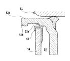
本実施形態では、クラッチ係合時のキャンセル室55からの作動油の速やかな排出と、クラッチ解除時のキャンセル室55からの作動油の流出阻止とを低コストかつ容易に達成するために、図3および図4に示されるような構成が採用されている。すなわち、ピストン52の外側筒状部52cの遊端部には、入力シャフトSに向けて突出する段部52dが全周にわたって形成されており、キャンセルプレート54の外周端部には、シール材60が全周にわたって固定されている。段部52dの最内周部は、キャンセルプレート54のシール材60の最外周部よりも入力シャフトSに近づいており、キャンセルプレート54は、シール材60(キャンセルプレート54の外周端部)がピストン52の外側筒状部52cの端面よりも径方向端部52b側に位置するようにクラッチドラム51に固定されている。   In the present embodiment, in order to achieve quick discharge of the hydraulic oil from the cancel chamber 55 when the clutch is engaged and prevention of the hydraulic oil from flowing out of the cancel chamber 55 when the clutch is released, it is easy to achieve at low cost. 3 and the configuration shown in FIG. 4 are employed. That is, a stepped portion 52 d that protrudes toward the input shaft S is formed over the entire circumference at the free end portion of the outer cylindrical portion 52 c of the piston 52, and the sealing material 60 is provided at the outer peripheral end portion of the cancel plate 54. Is fixed all around. The innermost peripheral portion of the stepped portion 52d is closer to the input shaft S than the outermost peripheral portion of the seal material 60 of the cancel plate 54, and the cancel plate 54 has the seal material 60 (the outer peripheral end portion of the cancel plate 54) as a piston. 52 is fixed to the clutch drum 51 so as to be positioned on the radial end 52b side of the end surface of the outer cylindrical portion 52c.

これにより、ピストン52による受圧板57の押圧が解除された状態(クラッチ解除状態)では、ピストン52の段部52dと、キャンセルプレート54のシール材60(キャンセルプレート54の外周端部)とが図3に示されるように互いに当接し合う。従って、ピストン52の段部52dは、クラッチ解除の際にキャンセルプレート54(シール材60)と協働して遠心油圧キャンセル室55からの作動油の流出を確実に阻止する。   Thereby, in a state where the pressure of the pressure receiving plate 57 by the piston 52 is released (clutch release state), the stepped portion 52d of the piston 52 and the sealing material 60 of the cancel plate 54 (the outer peripheral end portion of the cancel plate 54) are illustrated. 3 abut against each other. Therefore, the step 52d of the piston 52 cooperates with the cancel plate 54 (seal member 60) when releasing the clutch to reliably prevent the hydraulic oil from flowing out of the centrifugal hydraulic pressure cancel chamber 55.

これに対して、クラッチ係合のためにピストン52をキャンセルプレート54に向けて移動させると、図4に示されるように、ピストン52の段部52dとキャンセルプレート54のシール材60との間には流路(隙間)が形成されることになる。従って、クラッチ装置50では、クラッチ係合に際して、遠心油圧キャンセル室55内の作動油をキャンセル室55の外周側から外部へと速やかに排出させることができる。この結果、クラッチ装置50では、周囲温度が低く作動油の粘性が高いような場合であっても、クラッチ係合の開始から完了までのタイムラグを良好に低減可能となり、クラッチ係合を速やかに応答性よく実行することができる。なお、遠心油圧キャンセル室55の外周側から外部に流出した作動油は、クラッチドラム51の基部51aに形成された孔部51fを介して油圧系統へと戻される。   On the other hand, when the piston 52 is moved toward the cancel plate 54 for clutch engagement, as shown in FIG. 4, the gap between the step 52 d of the piston 52 and the sealing material 60 of the cancel plate 54 is obtained. A flow path (gap) is formed. Therefore, in the clutch device 50, when the clutch is engaged, the hydraulic oil in the centrifugal oil pressure cancel chamber 55 can be quickly discharged from the outer peripheral side of the cancel chamber 55 to the outside. As a result, in the clutch device 50, even when the ambient temperature is low and the viscosity of the hydraulic oil is high, the time lag from the start to the completion of the clutch engagement can be reduced well, and the clutch engagement is quickly responded. It can be performed well. The hydraulic fluid that has flowed outside from the outer peripheral side of the centrifugal hydraulic pressure cancellation chamber 55 is returned to the hydraulic system through a hole 51f formed in the base 51a of the clutch drum 51.

図5は、本発明によるクラッチ装置の変形例を示す断面図である。図5の例では、ピストン52の外側筒状部52cに段部を形成する代わりに、外側筒状部52cの遊端部に段部61dを有する段付シール材61が全周にわたって固定されている。また、キャンセルプレート54の外周端部には、シール材は取り付けられていない。かかる構成のもとでは、クラッチ解除状態では、ピストン52に取り付けられた段付シール材61の段部61dと、キャンセルプレート54の外周端部とが図5に示されるように互いに当接し合う。従って、ピストン52側の段部61dは、クラッチ解除の際にキャンセルプレート54と協働して遠心油圧キャンセル室55からの作動油の流出を確実に阻止する。   FIG. 5 is a sectional view showing a modification of the clutch device according to the present invention. In the example of FIG. 5, instead of forming a step portion on the outer cylindrical portion 52c of the piston 52, a stepped sealing material 61 having a step portion 61d at the free end portion of the outer cylindrical portion 52c is fixed over the entire circumference. Yes. Further, no sealing material is attached to the outer peripheral end of the cancel plate 54. Under such a configuration, in the clutch released state, the stepped portion 61d of the stepped seal material 61 attached to the piston 52 and the outer peripheral end of the cancel plate 54 abut against each other as shown in FIG. Accordingly, the step portion 61d on the piston 52 side prevents the hydraulic oil from flowing out of the centrifugal hydraulic pressure cancel chamber 55 in cooperation with the cancel plate 54 when releasing the clutch.

一方、クラッチ係合のためにピストン52をキャンセルプレート54に向けて移動させると、ピストン52に取り付けられた段付シール材61の段部61dとキャンセルプレート54の外周端部との間には流路(隙間)が形成され、遠心油圧キャンセル室55内の作動油は、キャンセル室55の外周側から外部へと速やかに流出する。このように、図5の構成を採用しても、クラッチ係合時のキャンセル室55からの作動油の速やかな排出と、クラッチ解除時のキャンセル室55からの作動油の流出阻止とを低コストかつ容易に達成することができる。   On the other hand, when the piston 52 is moved toward the cancel plate 54 for clutch engagement, there is no flow between the step portion 61 d of the stepped seal material 61 attached to the piston 52 and the outer peripheral end portion of the cancel plate 54. A path (gap) is formed, and the hydraulic oil in the centrifugal hydraulic pressure cancellation chamber 55 quickly flows out from the outer peripheral side of the cancellation chamber 55 to the outside. Thus, even if the configuration of FIG. 5 is adopted, it is possible to reduce the cost of quickly discharging the hydraulic oil from the cancel chamber 55 when the clutch is engaged and preventing the hydraulic oil from flowing out of the cancel chamber 55 when the clutch is released. And can be easily achieved.

図6および図7は、本発明によるクラッチ装置の他の変形例を示す断面図である。図6および図7の例では、ピストン52に対して段部を設ける代わりに、ピストン52の外側筒状部52cに孔部52hが形成されている。また、キャンセルプレート54は、クラッチドラム51の基部51aに向けて入力シャフトSと概ね平行に延出された外側筒状部54cを有しており、外側筒状部54cには、孔部54hが形成されている。   6 and 7 are sectional views showing other modified examples of the clutch device according to the present invention. In the example of FIGS. 6 and 7, a hole 52 h is formed in the outer cylindrical portion 52 c of the piston 52 instead of providing a step portion for the piston 52. The cancel plate 54 has an outer cylindrical portion 54c that extends substantially parallel to the input shaft S toward the base portion 51a of the clutch drum 51, and the outer cylindrical portion 54c has a hole 54h. Is formed.

図6に示されるように、ピストン52が図中最も右側に位置するクラッチ解除状態では、ピストン52の孔部52hとキャンセルプレート54の孔部54hとが重なり合うことはない。そして、ピストン52の外側筒状部52cとキャンセルプレート54の外側筒状部54cとの間には、クラッチ解除状態にある際に孔部52hと孔部54hとの間に位置するようにシール材62が全周にわたって介設されている。また、キャンセルプレート54の外側筒状部54cの両端部に対しても、シール材63および64が備えられている。これらのシール材62,63および64により、クラッチ解除状態では、遠心油圧キャンセル室55からの作動油の流出が確実に阻止される。   As shown in FIG. 6, the hole 52 h of the piston 52 and the hole 54 h of the cancel plate 54 do not overlap in the clutch release state where the piston 52 is located on the rightmost side in the drawing. A sealant is provided between the outer cylindrical portion 52c of the piston 52 and the outer cylindrical portion 54c of the cancel plate 54 so as to be positioned between the hole portion 52h and the hole portion 54h when the clutch is released. 62 is interposed over the entire circumference. Further, sealing materials 63 and 64 are also provided at both ends of the outer cylindrical portion 54c of the cancel plate 54. By these sealing materials 62, 63 and 64, in the clutch released state, the outflow of hydraulic oil from the centrifugal hydraulic pressure cancel chamber 55 is reliably prevented.

これに対して、クラッチ係合のためにピストン52をキャンセルプレート54に向けて移動させると、図7に示されるように、ピストン52の外側筒状部52cに形成された孔部52hと、キャンセルプレート54の外側筒状部54cに形成された孔部54hとが互いに連通するようになる。これにより、ピストン52の外周部とキャンセルプレート54の外周部との間に、孔部52hおよび54hを含む流路が形成されることになるので、遠心油圧キャンセル室55内の作動油をキャンセル室55の外周側から外部へと速やかに流出させることができる。このように、図6および図7に示される構成を採用しても、クラッチ係合時のキャンセル室55からの作動油の速やかな排出と、クラッチ解除時のキャンセル室55からの作動油の流出阻止とを低コストかつ容易に達成することができる。   On the other hand, when the piston 52 is moved toward the cancel plate 54 for clutch engagement, as shown in FIG. 7, the hole 52h formed in the outer cylindrical portion 52c of the piston 52 and the cancel The holes 54h formed in the outer cylindrical portion 54c of the plate 54 communicate with each other. As a result, a flow path including the holes 52h and 54h is formed between the outer peripheral portion of the piston 52 and the outer peripheral portion of the cancel plate 54, so that the hydraulic oil in the centrifugal hydraulic pressure cancel chamber 55 is removed from the cancel chamber. It is possible to quickly flow out from the outer peripheral side of 55 to the outside. Thus, even if the configuration shown in FIGS. 6 and 7 is adopted, the hydraulic oil is quickly discharged from the cancel chamber 55 when the clutch is engaged, and the hydraulic oil flows out from the cancel chamber 55 when the clutch is released. Prevention can be easily achieved at low cost.

以下、図8から図11を参照しながら、本発明によるクラッチ装置の第2実施形態について説明する。なお、上述の実施形態に関連して説明されたものと同一の要素には同一の参照符号が付され、重複する説明は省略される。   Hereinafter, a second embodiment of the clutch device according to the present invention will be described with reference to FIGS. Note that the same reference numerals are given to the same elements as those described in relation to the above-described embodiment, and redundant descriptions are omitted.

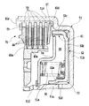
図8に示されるクラッチ装置50Aにおいても、ピストン52の外側筒状部52cの遊端部に、入力シャフトSに向けて突出する段部52dが全周にわたって形成されており、キャンセルプレート54の外周端部には、シール材60が全周にわたって固定されている。段部52dの最内周部は、キャンセルプレート54のシール材60の最外周部よりも入力シャフトSに近づいており、キャンセルプレート54は、シール材60(キャンセルプレート54の外周端部)がピストン52の外側筒状部52cの端面よりも径方向端部52b側に位置するようにクラッチドラム51に固定されている。そして、このクラッチ装置50Aでは、ピストン52の外側筒状部52cに、段部52dの軸方向内側に位置するように第2の段部52eが全周にわたって形成されている。第2の段部52eの最内周部は、キャンセルプレート54のシール材60の最外周部よりも僅かに入力シャフトSに近づいている。そして、段部52dと第2の段部52eとの間隔x(図9参照)は、シール材60が装着されたキャンセルプレート54の外周端部の軸方向長さよりも長く設定されている。   Also in the clutch device 50 </ b> A shown in FIG. 8, a step portion 52 d that protrudes toward the input shaft S is formed on the free end portion of the outer cylindrical portion 52 c of the piston 52, and the outer periphery of the cancel plate 54 is The sealing material 60 is fixed to the end part over the entire circumference. The innermost peripheral portion of the stepped portion 52d is closer to the input shaft S than the outermost peripheral portion of the seal material 60 of the cancel plate 54, and the cancel plate 54 has the seal material 60 (the outer peripheral end portion of the cancel plate 54) as a piston. 52 is fixed to the clutch drum 51 so as to be positioned on the radial end 52b side of the end surface of the outer cylindrical portion 52c. And in this clutch apparatus 50A, the 2nd step part 52e is formed in the outer cylindrical part 52c of the piston 52 over the perimeter so that it may be located in the axial direction inner side of the step part 52d. The innermost peripheral portion of the second stepped portion 52e is slightly closer to the input shaft S than the outermost peripheral portion of the sealing material 60 of the cancel plate 54. An interval x (see FIG. 9) between the stepped portion 52d and the second stepped portion 52e is set to be longer than the axial length of the outer peripheral end portion of the cancel plate 54 to which the sealing material 60 is attached.

このように構成されるクラッチ装置50Aでは、クラッチ係合のためにピストン52をキャンセルプレート54に向けて移動させると、図9に示されるように、ピストン52の段部52d(図中右端)とキャンセルプレート54のシール材60との間およびピストン52の段部52e(図中左端)とキャンセルプレート54のシール材60との間には流路(隙間)が形成されることになる。すなわち、段部52dと段部52eとの間では、キャンセルプレート54の外周部とピストン52との間に隙間が形成される。従って、クラッチ装置50Aにおいても、クラッチ係合に際して遠心油圧キャンセル室55内の作動油をキャンセル室55の外周側から外部へと速やかに排出させることができる。   In the clutch device 50A configured as described above, when the piston 52 is moved toward the cancel plate 54 for clutch engagement, as shown in FIG. 9, a step 52d (right end in the drawing) of the piston 52 A flow path (gap) is formed between the seal member 60 of the cancel plate 54 and between the step 52e (left end in the figure) of the piston 52 and the seal member 60 of the cancel plate 54. That is, a gap is formed between the outer peripheral portion of the cancel plate 54 and the piston 52 between the step portion 52d and the step portion 52e. Therefore, also in the clutch device 50A, the hydraulic oil in the centrifugal oil pressure cancel chamber 55 can be quickly discharged from the outer peripheral side of the cancel chamber 55 to the outside when the clutch is engaged.

そして、図9の状態からピストン52がキャンセルプレート54に対して更に接近し、クラッチ係合が概ね完了した時点では、図10に示されるように、ピストン52の第2の段部52eとキャンセルプレート54のシール材60とが当接するようになり、クラッチ係合の完了前にはピストン52の段部52e(図中左端)とキャンセルプレート54のシール材60との間の流路が閉鎖される。これにより、クラッチ装置50では、クラッチ係合が完了した際(実質的に完了した際)に、遠心油圧キャンセル室55内に作動流体を残留させることが可能となる。   Then, when the piston 52 further approaches the cancel plate 54 from the state of FIG. 9 and the clutch engagement is almost completed, as shown in FIG. 10, the second step portion 52e of the piston 52 and the cancel plate 54 is brought into contact with the seal member 60, and the flow path between the step 52e (left end in the figure) of the piston 52 and the seal member 60 of the cancel plate 54 is closed before the clutch engagement is completed. . Thereby, in the clutch device 50, when the clutch engagement is completed (substantially completed), the working fluid can be left in the centrifugal hydraulic pressure cancellation chamber 55.

この結果、クラッチ装置50Aでは、周囲温度が低く作動油の粘性が高いような場合であっても、クラッチ係合の開始から完了までのタイムラグを良好に低減可能となり、クラッチ係合を速やかに応答性よく実行することができる。また、クラッチ装置50Aでは、変速機5がドライブレンジからニュートラルあるいはパーキングレンジに設定されてクラッチ解除が実行される際、遠心油圧キャンセル室55内に残留した作動油からピストン52に対して遠心油圧による反力を作用させることができるので、クラッチ解除を速やかに応答性よく実行可能となる。   As a result, in the clutch device 50A, even when the ambient temperature is low and the viscosity of the hydraulic oil is high, the time lag from the start to completion of the clutch engagement can be satisfactorily reduced, and the clutch engagement is quickly responded. It can be performed well. Further, in the clutch device 50A, when the transmission 5 is set from the drive range to the neutral or parking range and the clutch is released, the hydraulic oil remaining in the centrifugal hydraulic pressure cancellation chamber 55 is subjected to the centrifugal hydraulic pressure with respect to the piston 52. Since the reaction force can be applied, the clutch can be released quickly and with good responsiveness.

なお、図11に示されるように、ピストン52の外側筒状部52cに段部52dおよび52eを形成する代わりに、外側筒状部52cの内周面に、段部61dと、この段部61dから所定間隔をおいて形成された第2の段部61eとを有する段付シール材61Aが全周にわたって固定されてもよい。これにより、ピストン52や段部61dおよび61eの耐久性を向上させることが可能となる。また、段付シール材61Aをピストン52に対して固定するだけで2つの段部61dおよび61eを形成することができるので、生産性を向上させることができる。更に、この場合、キャンセルプレート54の外周端部のシール材は省略され得ることから、その分だけキャンセルプレート54に要するコストを低減させることが可能となる。なお、段部61dと第2の段部61eとを有する段付シール材61Aの代わりに、ピストン52に第1および第2の段部が形成されるように、2つのシール材が外側筒状部52cの内周面に固定されてもよい。   As shown in FIG. 11, instead of forming the step portions 52d and 52e in the outer cylindrical portion 52c of the piston 52, a step portion 61d and the step portion 61d are formed on the inner peripheral surface of the outer cylindrical portion 52c. A stepped sealing material 61A having a second step portion 61e formed at a predetermined interval from the second step portion 61e may be fixed over the entire circumference. Thereby, it becomes possible to improve the durability of the piston 52 and the stepped portions 61d and 61e. Further, since the two step portions 61d and 61e can be formed only by fixing the stepped seal material 61A to the piston 52, the productivity can be improved. Further, in this case, since the seal material at the outer peripheral end of the cancel plate 54 can be omitted, the cost required for the cancel plate 54 can be reduced accordingly. In addition, instead of the stepped sealing material 61A having the stepped portion 61d and the second stepped portion 61e, the two sealing materials are formed in an outer cylindrical shape so that the first and second stepped portions are formed in the piston 52. You may fix to the internal peripheral surface of the part 52c.

図11の構成のもとでは、クラッチ係合のためにピストン52をキャンセルプレート54に向けて移動させると、ピストン52に固定された段付シール材61の段部61dとキャンセルプレート54の外周部との間および段付シール材61の段部61eとキャンセルプレート54の外周部との間には流路(隙間)が形成されることになる。そして、ピストン52にキャンセルプレートに対して更に接近し、クラッチ係合がほぼ完了した時点で、段付シール材61の段部61eとキャンセルプレート54とが当接するようになり、クラッチ係合の完了前には、段付シール材61の段部61eとキャンセルプレート54との間の流路が閉鎖される。   In the configuration of FIG. 11, when the piston 52 is moved toward the cancel plate 54 for clutch engagement, the step portion 61 d of the stepped seal material 61 fixed to the piston 52 and the outer peripheral portion of the cancel plate 54. A flow path (gap) is formed between the step portion 61 e of the stepped seal material 61 and the outer peripheral portion of the cancel plate 54. When the piston 52 further approaches the cancel plate and the clutch engagement is almost completed, the step portion 61e of the stepped seal material 61 comes into contact with the cancel plate 54, and the clutch engagement is completed. Before, the flow path between the step part 61e of the stepped sealing material 61 and the cancel plate 54 is closed.

これにより、図11の構成を採用しても、クラッチ係合に際して、遠心油圧キャンセル室55内の作動油をキャンセル室55の外周側から外部へと速やかに排出させることができる。従って、周囲温度が低く作動油の粘性が高いような場合であっても、クラッチ係合の開始から完了までのタイムラグを良好に低減可能となり、クラッチ係合を速やかに応答性よく実行することができる。また、図11の構成においても、クラッチ係合が完了した際に遠心油圧キャンセル室55内に作動流体を残留させることが可能となるので、クラッチ係合を解除する際に、遠心油圧キャンセル室55内に残留した作動油からピストン52に対して遠心油圧による反力を作用させることができる。従って、図11の構成を採用しても、クラッチ解除を速やかに応答性よく実行可能となる。   Accordingly, even when the configuration of FIG. 11 is adopted, the hydraulic oil in the centrifugal oil pressure cancel chamber 55 can be quickly discharged from the outer peripheral side of the cancel chamber 55 to the outside when the clutch is engaged. Therefore, even when the ambient temperature is low and the viscosity of the hydraulic oil is high, the time lag from the start to the completion of clutch engagement can be satisfactorily reduced, and the clutch engagement can be executed quickly and with good responsiveness. it can. Also in the configuration of FIG. 11, since the working fluid can remain in the centrifugal hydraulic pressure cancellation chamber 55 when the clutch engagement is completed, the centrifugal hydraulic pressure cancellation chamber 55 is released when the clutch engagement is released. A reaction force by centrifugal hydraulic pressure can be applied to the piston 52 from the hydraulic oil remaining inside. Therefore, even if the configuration of FIG. 11 is adopted, the clutch can be released quickly and with good responsiveness.

本発明によるクラッチ装置を含む車両用トランスアクスルの一部を示す断面図である。It is sectional drawing which shows a part of transaxle for vehicles containing the clutch apparatus by this invention. 図1のトランスアクスルに適用可能な他のトルクコンバータを示す断面図である。It is sectional drawing which shows the other torque converter applicable to the transaxle of FIG. 本発明によるクラッチ装置を示す断面図である。It is sectional drawing which shows the clutch apparatus by this invention. 本発明によるクラッチ装置を示す断面図である。It is sectional drawing which shows the clutch apparatus by this invention. 本発明によるクラッチ装置の変形例を示す断面図である。It is sectional drawing which shows the modification of the clutch apparatus by this invention. 本発明によるクラッチ装置の他の変形例を示す断面図である。It is sectional drawing which shows the other modification of the clutch apparatus by this invention. 本発明によるクラッチ装置の他の変形例を示す断面図である。It is sectional drawing which shows the other modification of the clutch apparatus by this invention. 本発明によるクラッチ装置の第2実施形態を示す断面図である。It is sectional drawing which shows 2nd Embodiment of the clutch apparatus by this invention. 図8のクラッチ装置の動作を説明するための拡大断面図である。It is an expanded sectional view for demonstrating operation | movement of the clutch apparatus of FIG. 図8のクラッチ装置の動作を説明するための拡大断面図である。It is an expanded sectional view for demonstrating operation | movement of the clutch apparatus of FIG. 本発明の第2実施形態における変形例を示す断面図である。It is sectional drawing which shows the modification in 2nd Embodiment of this invention.

符号の説明Explanation of symbols

1 トランスアクスル
5 ベルト式無段変速機
10,10A トルクコンバータ
19,19A ロックアップクラッチ機構
190 ロックアップピストン
190a 内周側端部
20 オイルポンプ
30 前後進切り換え機構
40 遊星歯車機構
50 クラッチ装置
51 クラッチドラム
51a 基部
51b 径方向端部
51c 外側筒状部
51s スプライン
52 ピストン
52a 基部
52b 径方向端部
52c 外側筒状部
52d,52e 段部
52h 孔部
53 油室
54 キャンセルプレート
54c 外側筒状部
54h 孔部
55 遠心油圧キャンセル室
60,62,63,64 シール材
61,61A 段付シール材
61d,61e 段部
70 リバースブレーキ
S 入力シャフト
DESCRIPTION OF SYMBOLS 1 Transaxle 5 Belt type continuously variable transmission 10, 10A Torque converter 19, 19A Lockup clutch mechanism 190 Lockup piston 190a Inner peripheral side end 20 Oil pump 30 Forward / reverse switching mechanism 40 Planetary gear mechanism 50 Clutch device 51 Clutch drum 51a Base 51b Radial end 51c Outer cylindrical part 51s Spline 52 Piston 52a Base 52b Radial end 52c Outer cylindrical part 52d, 52e Step part 52h Hole 53 Oil chamber 54 Cancel plate 54c Outer cylindrical part 54h Hole 55 Centrifugal hydraulic cancel chamber 60, 62, 63, 64 Sealing material 61, 61A Stepped sealing material 61d, 61e Stepped part 70 Reverse brake S Input shaft

Claims (7)

クラッチドラムと、前記クラッチドラム内に移動自在に配置されるピストンとを備え、クラッチ係合の際に前記クラッチドラムと前記ピストンとの間の油室に作動油を供給して前記ピストンを移動させるクラッチ装置において、
前記ピストンを挟んで前記油室の反対側に、作動油で満たされる遠心油圧キャンセル室を画成するキャンセルプレートを備え、前記クラッチ係合の際に、前記遠心油圧キャンセル室内の作動油が該遠心油圧キャンセル室の外周側から外部に排出されることを特徴とするクラッチ装置。
A clutch drum and a piston movably disposed in the clutch drum are provided, and hydraulic oil is supplied to an oil chamber between the clutch drum and the piston to move the piston when the clutch is engaged. In the clutch device,
A cancel plate defining a centrifugal hydraulic pressure cancellation chamber filled with hydraulic oil is provided on the opposite side of the oil chamber across the piston, and when the clutch is engaged, the hydraulic oil in the centrifugal hydraulic pressure cancellation chamber is A clutch device that is discharged to the outside from an outer peripheral side of a hydraulic pressure canceling chamber.
前記クラッチ係合のために前記ピストンを前記キャンセルプレートに向けて移動させると、前記ピストンの外周部と前記キャンセルプレートの外周部との間に流路が形成されることを特徴とする請求項1に記載のクラッチ装置。   2. The flow path is formed between an outer peripheral portion of the piston and an outer peripheral portion of the cancel plate when the piston is moved toward the cancel plate to engage the clutch. The clutch device according to 1. 前記ピストンは、前記キャンセルプレートの外周部と当接可能な段部を有し、当該段部は、クラッチ解除の際に前記キャンセルプレートと協働して前記遠心油圧キャンセル室からの作動油の流出を規制することを特徴とする請求項1または2に記載のクラッチ装置。   The piston has a stepped portion that can come into contact with the outer peripheral portion of the cancel plate, and the stepped portion cooperates with the cancel plate when the clutch is released, and hydraulic oil flows out of the centrifugal hydraulic pressure cancel chamber. The clutch device according to claim 1, wherein the clutch device is regulated. 前記ピストンの外周部および前記キャンセルプレートの外周部のそれぞれには孔部が形成されており、前記クラッチ係合のために前記ピストンを移動させると、前記ピストンの前記孔部と前記キャンセルプレートの前記孔部とが互いに連通することを特徴とする請求項1または2に記載のクラッチ装置。   A hole is formed in each of the outer periphery of the piston and the outer periphery of the cancel plate. When the piston is moved for engaging the clutch, the hole of the piston and the cancel plate The clutch device according to claim 1 or 2, wherein the hole portion communicates with each other. 前記クラッチ係合が完了する際に遠心油圧キャンセル室からの作動油の排出が規制されることを特徴とする請求項1から4の何れかに記載のクラッチ装置。   5. The clutch device according to claim 1, wherein when the engagement of the clutch is completed, the discharge of the hydraulic oil from the centrifugal hydraulic pressure cancellation chamber is restricted. 前記クラッチ係合のために前記ピストンを前記キャンセルプレートに向けて移動させると、前記ピストンの外周部と前記キャンセルプレートの外周部との間に流路が形成され、前記ピストンを前記キャンセルプレートに向けて更に移動させると、前記クラッチ係合の完了前に前記流路が閉鎖されることを特徴とする請求項5に記載のクラッチ装置。   When the piston is moved toward the cancel plate to engage the clutch, a flow path is formed between the outer peripheral portion of the piston and the outer peripheral portion of the cancel plate, and the piston faces the cancel plate. The clutch device according to claim 5, wherein when further moved, the flow path is closed before the clutch engagement is completed. 前記ピストンは、前記キャンセルプレートの外周部と当接可能な第1の段部と、この第1の段部よりも内側に形成されており、前記キャンセルプレートの外周部と当接可能な第2の段部とを含み、前記第1の段部と前記第2の段部との間では、前記キャンセルプレートの外周部と前記ピストンとの間に隙間が形成されることを特徴とする請求項6に記載のクラッチ装置。
The piston is formed on the inner side of the first step portion that can come into contact with the outer peripheral portion of the cancel plate and the second step portion that can come into contact with the outer peripheral portion of the cancel plate. A gap is formed between the first step portion and the second step portion between the outer peripheral portion of the cancel plate and the piston. 6. The clutch device according to 6.
JP2004309823A 2004-03-17 2004-10-25 Clutch device Pending JP2005299920A (en)

Priority Applications (1)

Application Number Priority Date Filing Date Title
JP2004309823A JP2005299920A (en) 2004-03-17 2004-10-25 Clutch device

Applications Claiming Priority (2)

Application Number Priority Date Filing Date Title
JP2004076993 2004-03-17
JP2004309823A JP2005299920A (en) 2004-03-17 2004-10-25 Clutch device

Publications (1)

Publication Number Publication Date
JP2005299920A true JP2005299920A (en) 2005-10-27

Family

ID=35331679

Family Applications (1)

Application Number Title Priority Date Filing Date
JP2004309823A Pending JP2005299920A (en) 2004-03-17 2004-10-25 Clutch device

Country Status (1)

Country Link
JP (1) JP2005299920A (en)

Cited By (2)

* Cited by examiner, † Cited by third party
Publication number Priority date Publication date Assignee Title
JP2020173017A (en) * 2019-04-15 2020-10-22 トヨタ自動車株式会社 Hydraulic clutch
JP2021181804A (en) * 2020-05-19 2021-11-25 Nok株式会社 Sealing device

Cited By (3)

* Cited by examiner, † Cited by third party
Publication number Priority date Publication date Assignee Title
JP2020173017A (en) * 2019-04-15 2020-10-22 トヨタ自動車株式会社 Hydraulic clutch
JP2021181804A (en) * 2020-05-19 2021-11-25 Nok株式会社 Sealing device
JP7458240B2 (en) 2020-05-19 2024-03-29 Nok株式会社 sealing device

Similar Documents

Publication Publication Date Title
JP4935006B2 (en) Fluid transmission device
JP5621916B2 (en) Starting device
JP4720301B2 (en) Automatic transmission clutch device
US10138949B2 (en) Friction engagement element
JP3097439B2 (en) Oil passage structure for continuously variable transmission
US9784345B2 (en) Transmission device
US9719579B2 (en) Speed change device
JP6217740B2 (en) Power transmission device
US9709133B2 (en) Speed change device
KR20070112887A (en) Beltless CVT
JP4720302B2 (en) Automatic transmission clutch device
JP2008309317A (en) Starter
US20070298925A1 (en) Fluid passage structure
JP2000283188A (en) Fluid coupling device
JP2015161340A (en) friction engagement device
JP4776209B2 (en) Automatic transmission
JP6173814B2 (en) clutch
JP2004286144A (en) Auxiliary equipment drive
US20050167234A1 (en) Clutch-purpose hydraulic servo
JP4821174B2 (en) Transmission clutch structure
WO2017022699A1 (en) Power-split-type continuously variable transmission and oil supply structure
JP4585087B2 (en) Automatic transmission
JP2005299698A (en) Belt type continuously variable transmission
JP3269419B2 (en) Belt type pulley device
JP2020076475A (en) Start device and power transmission device