JP2005299893A - Carrier plate and manufacturing method thereof - Google Patents
Carrier plate and manufacturing method thereof Download PDFInfo
- Publication number
- JP2005299893A JP2005299893A JP2004120803A JP2004120803A JP2005299893A JP 2005299893 A JP2005299893 A JP 2005299893A JP 2004120803 A JP2004120803 A JP 2004120803A JP 2004120803 A JP2004120803 A JP 2004120803A JP 2005299893 A JP2005299893 A JP 2005299893A
- Authority
- JP
- Japan
- Prior art keywords
- plate
- carrier plate
- wall
- side wall
- plate portion
- Prior art date
- Legal status (The legal status is an assumption and is not a legal conclusion. Google has not performed a legal analysis and makes no representation as to the accuracy of the status listed.)
- Granted
Links
Images
Classifications
-
- F—MECHANICAL ENGINEERING; LIGHTING; HEATING; WEAPONS; BLASTING
- F16—ENGINEERING ELEMENTS AND UNITS; GENERAL MEASURES FOR PRODUCING AND MAINTAINING EFFECTIVE FUNCTIONING OF MACHINES OR INSTALLATIONS; THERMAL INSULATION IN GENERAL
- F16H—GEARING
- F16H57/00—General details of gearing
- F16H57/08—General details of gearing of gearings with members having orbital motion
- F16H57/082—Planet carriers
Landscapes
- Engineering & Computer Science (AREA)
- General Engineering & Computer Science (AREA)
- Mechanical Engineering (AREA)
- Retarders (AREA)
- General Details Of Gearings (AREA)
- Structure Of Transmissions (AREA)
Abstract
【課題】剛性の高い脚部を有するキャリアプレートとその製造方法とを提供することを課題とする。
【解決手段】本発明のキャリアプレートは、ギヤを支持するプレート部と、このプレート部の外縁部に軸方向に延在する複数の脚部とを有するキャリアプレートであって、前記脚部の少なくとも一部がプレート部に塑性締結されていることを特徴とする。
【選択図】図2An object of the present invention is to provide a carrier plate having legs with high rigidity and a manufacturing method thereof.
A carrier plate according to the present invention is a carrier plate having a plate portion that supports a gear and a plurality of legs extending in an axial direction on an outer edge portion of the plate portion, and at least of the legs. A part is plastically fastened to the plate portion.
[Selection] Figure 2
Description
本発明はキャリアプレートとその製造方法に関し、さらに詳しくは、例えば、歯車やプーリなど、回転体を回転自在に支持するキャリアのキャリアプレートとその製造方法に関するものである。 The present invention relates to a carrier plate and a manufacturing method thereof, and more particularly to a carrier plate of a carrier that rotatably supports a rotating body such as a gear and a pulley, and a manufacturing method thereof.
一般に、自動車の自動変速機には遊星歯車装置が設けられており、遊星歯車装置は、リングギヤ、サンギヤ、これらリングギヤとサンギヤとに噛合するピニオン及びこのピニオンを支持するキャリアとで構成されている。 In general, an automatic transmission of an automobile is provided with a planetary gear device, and the planetary gear device includes a ring gear, a sun gear, a pinion that meshes with the ring gear and the sun gear, and a carrier that supports the pinion.
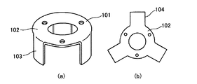
図4は、この様な遊星歯車装置のキャリアプレートの一例を示すものである(特許文献1参照)。このキャリアプレート101は、ピニオンギヤの支軸を支持する中空円盤状のキャリア本体102と、該キャリア本体102の外周端から軸方向に延びる複数の舌片状の脚部103とからなっている。
FIG. 4 shows an example of a carrier plate of such a planetary gear device (see Patent Document 1). The
そして、このキャリアプレート101は、プレスで打ち抜かれた円板状の打ち抜き素材から舌片状の脚部を有するキャリア素材(ブランクとも云う)104を打ち抜き、その後キャリア素材104の脚部103を軸方向に折り曲げて形成される。キャリア素材104は、図4(b)に示すように、打ち抜き形成された中空円板状のキャリア本体102の外周に複数の舌片状の脚部103が放射状に等間隔で配置されている。
The
また、遊星歯車装置のキャリア構造であって、脚部の断面形状をV字、M字、L字、U字などに形成することによって、耐久性の向上及びギヤノイズの低減を図るようにしたキャリアも開示されている(特許文献2参照)。
しかしながら、前者においては、キャリアプレートのプレート部に連続する脚部を単に軸線方向へ折り曲げたのみであるため、脚部の厚さはプレート部の厚さと同一であり、このため剛性の低いものとなっている。脚部の剛性が低いと、キャリアのねじり変形に脚部が耐えられず歯車の噛み合いズレを招き、耐久性の悪化やギヤノイズの増大といった問題を生じることがある。 However, in the former, since the leg portion continuous to the plate portion of the carrier plate is simply bent in the axial direction, the thickness of the leg portion is the same as the thickness of the plate portion, so that the rigidity is low. It has become. If the rigidity of the leg portion is low, the leg portion cannot endure the torsional deformation of the carrier, causing meshing misalignment, which may cause problems such as deterioration in durability and increase in gear noise.
また、後者においては、材料鋼板の歩留まりが従来構造よりも低下することと、且つ、製造工程が複雑であり製造コストの上昇を招く虞があるという問題がある。 In the latter case, there are problems that the yield of the steel plate is lower than that of the conventional structure, and that the manufacturing process is complicated and the manufacturing cost may increase.
本発明は、以上のような問題を解決すべくなされたものであって、剛性の高い脚部を有するキャリアプレートとその製造方法とを提供することを課題とする。 The present invention has been made to solve the above-described problems, and an object of the present invention is to provide a carrier plate having a highly rigid leg portion and a manufacturing method thereof.
本発明のキャリアプレートは、ギヤを支持するプレート部と、このプレート部の外縁部に軸方向に延在する複数の脚部とを有するキャリアプレートであって、
脚部の少なくとも一部がプレート部に塑性締結されていることを特徴とする。
The carrier plate of the present invention is a carrier plate having a plate portion supporting a gear and a plurality of legs extending in the axial direction on the outer edge portion of the plate portion,
It is characterized in that at least a part of the leg portion is plastically fastened to the plate portion.
本発明のキャリアプレートは、脚部は外壁とこの外壁に連続する側壁とで構成され、少なくとも側壁の一部がプレート部に塑性締結されていることが望ましい。 In the carrier plate of the present invention, it is desirable that the leg portion is composed of an outer wall and a side wall continuous to the outer wall, and at least a part of the side wall is plastically fastened to the plate portion.
また、本発明の好ましい形態では、脚部はさらに上記の側壁に連続する内壁を備え、この内壁の一部が塑性締結されている。 In a preferred embodiment of the present invention, the leg portion further includes an inner wall continuous with the side wall, and a part of the inner wall is plastically fastened.
本発明のキャリアプレートの製造方法は、ギヤを支持するプレート部と、このプレート部の外縁部に軸方向に延在する複数の脚部とを有するキャリアプレートの製造方法であって、材料素材から複数の嵌合穴を有するプレート部と、このプレート部から外周側に放射状に延在し前記嵌合穴と嵌合する凸部を有する複数の舌部と、を備えるブランクを形成するブランク打ち抜き工程と、舌部の両端部を折り曲げて側壁を形成する第1の曲げ工程と、側壁を形成した舌部を軸線方向に折り曲げて凸部を嵌合穴に嵌合させる第2の曲げ工程と、嵌合穴に嵌合された凸部を塑性締結する締結工程とを有することを特徴とする。 The carrier plate manufacturing method of the present invention is a method of manufacturing a carrier plate having a plate portion for supporting a gear and a plurality of legs extending in the axial direction on the outer edge portion of the plate portion. A blank punching process for forming a blank comprising a plate portion having a plurality of fitting holes and a plurality of tongue portions extending radially from the plate portion to the outer peripheral side and having convex portions fitted to the fitting holes. A first bending step of bending the both end portions of the tongue portion to form a side wall, a second bending step of bending the tongue portion forming the side wall in the axial direction and fitting the convex portion into the fitting hole, And a fastening step of plastically fastening the convex portion fitted in the fitting hole.
本発明のキャリアプレートは、キャリアプレートの脚部を構成する側壁をプレート部に塑性締結したので、脚部は高い強度と剛性を有する。従って、キャリアのねじり変形によって歯車の噛み合いズレを生じて、キャリアの耐久性の悪化やギヤノイズの増大といった問題を生じることがない。 In the carrier plate according to the present invention, since the side wall constituting the leg portion of the carrier plate is plastically fastened to the plate portion, the leg portion has high strength and rigidity. Therefore, the meshing of the gears is not caused by the torsional deformation of the carrier, and there is no problem that the durability of the carrier is deteriorated or the gear noise is increased.
また、脚部の側壁とプレート部とを塑性締結(例えば、かしめなど)により固着するようにしたので、溶接などの接合方法に比べて遙かに容易であり生産性を向上することができる。さらに、本発明のキャリアプレートは鋼板のプレス成形で得ることができるので、軽量、小型とすることができ製造コストを低減することができる。 Further, since the side wall of the leg portion and the plate portion are fixed by plastic fastening (for example, caulking or the like), it is much easier than a joining method such as welding, and productivity can be improved. Furthermore, since the carrier plate of the present invention can be obtained by press forming of a steel plate, it can be reduced in weight and size, and the manufacturing cost can be reduced.
以下、実施例によって本発明を詳細に説明する。 Hereinafter, the present invention will be described in detail by way of examples.
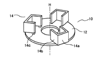
厚さ5mmのSPH370−OD(板材)を用いて、図1の斜視図に示すにキャリアプレート10を作製した。
A
図1のキャリアプレート10は、ギヤを支持するプレート部12と、プレート部12の外縁部に軸線H方向に延在する3本の脚部14とを有している。脚部14は外壁14aとこの外壁14aに連続する側壁14bとで構成され、外壁14aはプレート部12の外縁部に垂直に突出しており、側壁14bは外壁14bの両側に連続してほぼコの字状にプレート部12上に立設されている。そして、側壁14bの先端14c(点線で示す)がプレート部12に嵌入して塑性締結されている。このように脚部14はプレート部に固着されているので、極めて高い強度と剛性を有する。
The
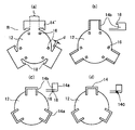
この様な脚部14を有するキャリアプレート10は次のようにして製造することができる。まず、材料鋼板から図2(a)に示す形状のブランクBを打ち抜く。ブランクBは、複数の嵌合穴16を有するプレート部12と、プレート部12から外周側に放射状に延在し、嵌合穴16と嵌合する凸部18を有する3個の舌部14’と、を備えている。ここで、凸部18の突出長さdはプレート部の厚さtより僅かに長く形成する。つまり、d=1.4〜1.8tであることが望ましい。突出長さdが1.4tよりも短いと締結が十分でなく所望の締結強度を得ることができない。また、1.8tを越えて長いと突出部が座屈することがあり、安定した締結強度を得ることができない。次に、第1の曲げ工程(b)で舌部14’の両端部を折り曲げ線Lに沿って曲げ、側壁14bを形成する。さらに、第2の曲げ工程(c)で側壁14bを形成した舌部14’を軸線H方向に折り曲げて外壁14aを形成するとともに、凸部18を嵌合穴16に嵌合させる。続いて、締結工程(d)では、嵌合穴16に嵌合された凸部18の先端をかしめて塑性締結し、締結部14cを形成する。最後にプレート中央に所定の軸穴を打ち抜き形成する。本実施例では、塑性締結をかしめとしたが、凸部の先端をプレート部に密着するように折り曲げてもよい。
The
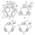
本実施例は、実施例1の脚部14にさらに内壁を設けて断面ロの字状の脚部としたものであり、内壁の一部もプレート部と塑性締結したものである。本実施例のキャリアプレートは実施例1に比べてさらに高い強度と剛性を有することができる。
In this embodiment, an inner wall is further provided on the
この様な脚部14を有するキャリアプレートは図3ようにして製造することができる。まず、材料鋼板から実施例1と同様にプレート部12と舌部14’とを有するブランクBを打ち抜く。本実施例では、図3に示すように、プレート部12には、実施例1と同様の嵌合穴16とともに、嵌合穴16’を形成する。また、舌部14’は、実施例1の舌部14’の側壁となる部分14b’の両側にさらに内壁となる部分14d’を配設し、内壁部分14d’に嵌合穴16’と嵌合する凸部18’を形成する。ここで、凸部18、18’の突出長さは、いずれも実施例1と同様にすることが望ましい。次に、第1の曲げ工程(b)で舌部14’を折り曲げ線L1およびL2に沿って曲げ、断面ロの字形状の筒体を形成する。次いで、第2の曲げ工程(c)で筒体を形成した舌部14’を軸線H方向に折り曲げて外壁14aを形成するとともに、凸部18を嵌合穴16に、また、凸部18’を嵌合穴16’に嵌合させる。続いて、締結工程(d)では、各嵌合穴16、16’に嵌合された各凸部18、18’の先端をかしめてプレート部12に塑性締結する。最後にプレート中央に所定の軸穴を打ち抜き形成する。なお、締結工程では、実施例1と同様にかしめ以外の適当な方法を用いてもよい。
A carrier plate having such a
なお、本発明のキャリアプレートは、上記の実施例に限定されるものではなく、本発明の主旨を逸脱しない範囲で変更することができる。例えば、実施例1では外壁と側壁とを断面略コの字状に配設したが、外壁に対向する側壁の開口部が外壁の幅よりも広くても、また、狭くてもよい。 In addition, the carrier plate of this invention is not limited to said Example, It can change in the range which does not deviate from the main point of this invention. For example, in Embodiment 1, the outer wall and the side wall are arranged in a substantially U-shaped cross section, but the opening of the side wall facing the outer wall may be wider or narrower than the width of the outer wall.
本発明のキャリアプレートは、プレス成形という極めて簡便な方法で得ることができ、軽量で高強度であるので、自動車の無段変速機、自動変速機などの遊星歯車装置のプラネタリキャリアに好適に用いることができる。 The carrier plate of the present invention can be obtained by a very simple method of press molding, and is lightweight and high in strength. Therefore, the carrier plate is suitably used for planetary carriers of planetary gear devices such as continuously variable transmissions and automatic transmissions of automobiles. be able to.
10:キャリアプレート 12:プレート部 14:脚部 16、16’:嵌合穴 18、18’:凸部 14a:外壁 14b:側壁 14c:嵌合部 14d:内壁 14’:舌部 B:ブランク
10: carrier plate 12: plate portion 14:
Claims (4)
前記脚部の少なくとも一部が前記プレート部に塑性締結されていることを特徴とするキャリアプレート。 A carrier plate having a plate portion for supporting a gear and a plurality of leg portions extending in an axial direction at an outer edge portion of the plate portion;
A carrier plate, wherein at least a part of the leg portion is plastically fastened to the plate portion.
材料素材から複数の嵌合穴を有する前記プレート部と、該プレート部から外周側に放射状に延在し前記嵌合穴と嵌合する凸部を有する複数の舌部と、を備えるブランクを形成するブランク打ち抜き工程と、
前記舌部の両端部を折り曲げて側壁を形成する第1の曲げ工程と、
前記側壁を形成した舌部を軸線方向に折り曲げて前記凸部を前記嵌合穴に嵌合させる第2の曲げ工程と、
前記嵌合穴に嵌合された凸部を塑性締結する締結工程と、
を有することを特徴とするキャリアプレートの製造方法。 A method of manufacturing a carrier plate having a plate portion for supporting a gear and a plurality of leg portions extending in an axial direction on an outer edge portion of the plate portion,
Forming a blank comprising the plate portion having a plurality of fitting holes from a material material, and a plurality of tongue portions having convex portions extending radially from the plate portion to the outer peripheral side and fitting with the fitting holes Blank punching process to
A first bending step of bending both ends of the tongue to form a side wall;
A second bending step of bending the tongue portion forming the side wall in the axial direction and fitting the convex portion into the fitting hole;
A fastening step of plastically fastening the convex portion fitted in the fitting hole;
A method for producing a carrier plate, comprising:
Priority Applications (1)
| Application Number | Priority Date | Filing Date | Title |
|---|---|---|---|
| JP2004120803A JP4103840B2 (en) | 2004-04-15 | 2004-04-15 | Carrier plate and manufacturing method thereof |
Applications Claiming Priority (1)
| Application Number | Priority Date | Filing Date | Title |
|---|---|---|---|
| JP2004120803A JP4103840B2 (en) | 2004-04-15 | 2004-04-15 | Carrier plate and manufacturing method thereof |
Publications (2)
| Publication Number | Publication Date |
|---|---|
| JP2005299893A true JP2005299893A (en) | 2005-10-27 |
| JP4103840B2 JP4103840B2 (en) | 2008-06-18 |
Family
ID=35331656
Family Applications (1)
| Application Number | Title | Priority Date | Filing Date |
|---|---|---|---|
| JP2004120803A Expired - Lifetime JP4103840B2 (en) | 2004-04-15 | 2004-04-15 | Carrier plate and manufacturing method thereof |
Country Status (1)
| Country | Link |
|---|---|
| JP (1) | JP4103840B2 (en) |
Cited By (2)
| Publication number | Priority date | Publication date | Assignee | Title |
|---|---|---|---|---|
| JP2009262232A (en) * | 2008-03-31 | 2009-11-12 | Jfe Steel Corp | Branch member forming method, and branch member |
| CN111094801A (en) * | 2017-09-05 | 2020-05-01 | 爱信艾达株式会社 | Planetary carrier and manufacturing method thereof |
-
2004
- 2004-04-15 JP JP2004120803A patent/JP4103840B2/en not_active Expired - Lifetime
Cited By (4)
| Publication number | Priority date | Publication date | Assignee | Title |
|---|---|---|---|---|
| JP2009262232A (en) * | 2008-03-31 | 2009-11-12 | Jfe Steel Corp | Branch member forming method, and branch member |
| CN111094801A (en) * | 2017-09-05 | 2020-05-01 | 爱信艾达株式会社 | Planetary carrier and manufacturing method thereof |
| EP3633241A4 (en) * | 2017-09-05 | 2020-07-15 | Aisin Aw Co., Ltd. | PLANET CARRIER AND METHOD FOR THE PRODUCTION THEREOF |
| CN111094801B (en) * | 2017-09-05 | 2023-02-28 | 株式会社爱信 | Planet carrier and manufacturing method thereof |
Also Published As
| Publication number | Publication date |
|---|---|
| JP4103840B2 (en) | 2008-06-18 |
Similar Documents
| Publication | Publication Date | Title |
|---|---|---|
| JP5448184B2 (en) | Spring assembly and manufacturing method thereof | |
| JP2670952B2 (en) | Planet carrier of planetary gear unit | |
| JP2002364651A (en) | Rolling bearing retainer | |
| JP2017026083A (en) | Retainer for radial needle bearing, and method of manufacturing the same | |
| JP2002276740A (en) | Belt device and method of manufacturing the same | |
| JP4103840B2 (en) | Carrier plate and manufacturing method thereof | |
| JP2003034106A (en) | Axle housing and method of manufacturing the same | |
| US7243770B2 (en) | Clutch assembly including strengthening members | |
| JP3953044B2 (en) | Carrier plate and manufacturing method thereof | |
| JP4103839B2 (en) | Carrier plate and manufacturing method thereof | |
| JP2005076697A (en) | Ball-cage for combined roller bearing | |
| KR20120116343A (en) | Manufacturing method of gear structure and intermediate structure of gear structure | |
| JPH01307530A (en) | Spring assembly | |
| JPH07133848A (en) | Carrier assembly body for automatic transmission | |
| JP2000329214A (en) | Assembled camshaft and method of manufacturing the same | |
| JP2005517854A (en) | Method for manufacturing a cover that fits over the end of an exhaust pipe of a motor vehicle, and a cover manufactured according to this method | |
| US6645119B2 (en) | Pinion carrier assembly for an automatic transmission | |
| US20240369099A1 (en) | Axial rolling bearing unit with rolling bodies, which are arranged between annular axial bearing washers, and a functionally integrated bearing cage | |
| JP5168440B2 (en) | Driving part fastening method and driving part | |
| JP3385513B2 (en) | Carrier manufacturing method | |
| JPH10288248A (en) | Planetary gear system for automatic transmission | |
| JP4103842B2 (en) | Ravinio type planetary carrier and method for producing the same | |
| CN111542706A (en) | Needle thrust bearing and method for producing a runner disk for such a needle thrust bearing | |
| JP2001140995A (en) | Planetary gear device | |
| JP4449553B2 (en) | Carrier manufacturing method |
Legal Events
| Date | Code | Title | Description |
|---|---|---|---|
| A621 | Written request for application examination |
Free format text: JAPANESE INTERMEDIATE CODE: A621 Effective date: 20060823 |
|
| A977 | Report on retrieval |
Free format text: JAPANESE INTERMEDIATE CODE: A971007 Effective date: 20070405 |
|
| A131 | Notification of reasons for refusal |
Free format text: JAPANESE INTERMEDIATE CODE: A131 Effective date: 20070410 |
|
| A521 | Written amendment |
Free format text: JAPANESE INTERMEDIATE CODE: A523 Effective date: 20070606 |
|
| TRDD | Decision of grant or rejection written | ||
| A01 | Written decision to grant a patent or to grant a registration (utility model) |
Free format text: JAPANESE INTERMEDIATE CODE: A01 Effective date: 20080304 |
|
| A61 | First payment of annual fees (during grant procedure) |
Free format text: JAPANESE INTERMEDIATE CODE: A61 Effective date: 20080317 |
|
| R151 | Written notification of patent or utility model registration |
Ref document number: 4103840 Country of ref document: JP Free format text: JAPANESE INTERMEDIATE CODE: R151 |
|
| FPAY | Renewal fee payment (event date is renewal date of database) |
Free format text: PAYMENT UNTIL: 20110404 Year of fee payment: 3 |
|
| FPAY | Renewal fee payment (event date is renewal date of database) |
Free format text: PAYMENT UNTIL: 20120404 Year of fee payment: 4 |
|
| FPAY | Renewal fee payment (event date is renewal date of database) |
Free format text: PAYMENT UNTIL: 20130404 Year of fee payment: 5 |
|
| FPAY | Renewal fee payment (event date is renewal date of database) |
Free format text: PAYMENT UNTIL: 20140404 Year of fee payment: 6 |