JP2005299729A - Wet multi-plate clutch device - Google Patents
Wet multi-plate clutch device Download PDFInfo
- Publication number
- JP2005299729A JP2005299729A JP2004113244A JP2004113244A JP2005299729A JP 2005299729 A JP2005299729 A JP 2005299729A JP 2004113244 A JP2004113244 A JP 2004113244A JP 2004113244 A JP2004113244 A JP 2004113244A JP 2005299729 A JP2005299729 A JP 2005299729A
- Authority
- JP
- Japan
- Prior art keywords
- rotating member
- shaft
- hollow portion
- wet multi
- clutch device
- Prior art date
- Legal status (The legal status is an assumption and is not a legal conclusion. Google has not performed a legal analysis and makes no representation as to the accuracy of the status listed.)
- Pending
Links
- 230000008878 coupling Effects 0.000 claims description 2
- 238000010168 coupling process Methods 0.000 claims description 2
- 238000005859 coupling reaction Methods 0.000 claims description 2
- 230000005540 biological transmission Effects 0.000 abstract description 16
- 239000010720 hydraulic oil Substances 0.000 description 11
- 239000003921 oil Substances 0.000 description 10
- 239000010687 lubricating oil Substances 0.000 description 9
- 230000002093 peripheral effect Effects 0.000 description 7
- 238000001816 cooling Methods 0.000 description 3
- 239000003638 chemical reducing agent Substances 0.000 description 2
- 230000001050 lubricating effect Effects 0.000 description 2
- 238000007789 sealing Methods 0.000 description 2
- 238000005452 bending Methods 0.000 description 1
- 239000012530 fluid Substances 0.000 description 1
- 239000002783 friction material Substances 0.000 description 1
- 238000009434 installation Methods 0.000 description 1
- 239000000463 material Substances 0.000 description 1
- 230000001105 regulatory effect Effects 0.000 description 1
Images


Landscapes
- Hydraulic Clutches, Magnetic Clutches, Fluid Clutches, And Fluid Joints (AREA)
Abstract
【課題】トルク伝達容量が大きく、しかもトルク伝達制限機構としても使用することができ、原動機側または被動機側の連結軸上に設置可能な、全長の短い、小型軽量の湿式多板クラッチ装置を提供することを目的としている。
【解決手段】ケーシング12と、このケーシング12内に設けられた、駆動側回転部材2および被動側回転部材3と、これらの回転部材の間に配置され、各回転部材と一体に回転可能であると共にその軸方向に移動可能な多数のクラッチ板17,19と、これらのクラッチ板を押圧するための押圧部材5と、この押圧部材5に押圧力を供給するための押圧力供給手段6とからなる湿式多板クラッチ装置において、少なくとも一方の回転部材2に中空部2aを形成し、その中空部2a内に他方の回転部材3を挿入し、他方の回転部材3が中空部内において軸受10,11を介して一方の回転部材2を支持すると共に駆動源からの動力を伝達する回転軸や被動機へ動力を伝達するための回転軸32に結合し、支持されるものである。
【選択図】図1A small and lightweight wet multi-plate clutch device having a short total length and having a large torque transmission capacity, which can be used as a torque transmission limiting mechanism and can be installed on a connecting shaft on a prime mover side or a driven machine side. It is intended to provide.
A casing 12, a driving side rotating member 2 and a driven side rotating member 3 provided in the casing 12, and the rotating member are disposed between the rotating members, and can rotate integrally with the rotating members. In addition, a large number of clutch plates 17 and 19 that are movable in the axial direction, a pressing member 5 for pressing these clutch plates, and a pressing force supply means 6 for supplying pressing force to the pressing member 5 In the wet multi-plate clutch device, a hollow portion 2a is formed in at least one rotating member 2, the other rotating member 3 is inserted into the hollow portion 2a, and the other rotating member 3 is a bearing 10, 11 in the hollow portion. The rotary member 2 is supported via the rotary shaft and coupled to and supported by a rotary shaft for transmitting power from a drive source and a rotary shaft 32 for transmitting power to a driven machine.
[Selection] Figure 1
Description
この発明は、湿式多板クラッチ装置に関し、特に、動力の接続、遮断を行うとともに、必要に応じてトルク制限機能を備えることのできる湿式多板クラッチ装置に関するものである。 The present invention relates to a wet multi-plate clutch device, and more particularly, to a wet multi-plate clutch device that can connect and disconnect power and provide a torque limiting function as necessary.
従来の典型的な湿式多板クラッチ装置は、例えば、特許文献1に示されているように、ケーシング内に設けられた、入力軸および出力軸と、これらの軸の間に、各軸と一体に回転可能であると共にその軸方向に移動可能に配置された多数のクラッチ板と、このクラッチ板を押圧するための押圧部材と、この押圧部材に押圧力を供給するための押圧力供給手段とから構成されている。
For example, as shown in
すなわち、図6に示されるように、従来の湿式多板クラッチ装置1は、入力軸2および出力軸3と、これらの軸2,3の間に、多数のクラッチ板4が入力軸2および出力軸3とそれぞれ一体に回転可能であると共に、その軸方向に移動可能に配置されている。したがって、このクラッチ板4は、押圧力供給手段である油圧ポンプ6の作動により押圧部材である作動ピストン5が移動するとき、作動ピストン5に押圧されて互いに密着し、入力軸2の回転を出力軸3に伝達できる。なお、油圧ポンプ6が作動せず、作動ピストン5に作動油が供給されないときは、各クラッチ板4は相対的に空転し、入力軸2の回転が出力軸3へ伝達されることはない。なお、7は、駆動源である原動機の出力軸に入力軸を接続するための入力フランジであり、8は、発電機などの被動機の入力軸に接続するための出力フランジである。
That is, as shown in FIG. 6, the conventional wet
この種の湿式多板クラッチ装置は、入力軸と出力軸とが油圧クラッチを挟んで左右に対向して配置され、各軸の端部はケーシングに設けられた複数の軸受によってそれぞれ支持されているので、クラッチ装置全体の長さが長くなり、広い設置スペースを必要とする。したがって、限られたスペースに後から装置を追設しようとする場合や原動機と被動機を含めた機械設備全体の長さに制約がある場合などの適用には不向きであった。 In this type of wet multi-plate clutch device, an input shaft and an output shaft are arranged to face each other with a hydraulic clutch interposed therebetween, and ends of the respective shafts are respectively supported by a plurality of bearings provided in a casing. Therefore, the length of the entire clutch device becomes long and a large installation space is required. Therefore, it is unsuitable for applications such as when an apparatus is to be added later in a limited space or when the length of the entire mechanical equipment including the prime mover and the driven machine is limited.
また、原動機から減速装置を介して発電機を駆動する発電機駆動装置においては、発電機に所定以上の負荷がかかった時に、原動機の損傷を防止するために、一般に原動機(減速機を含む。)と発電機との間の継手部にシャーピンが設けられているが、シャーピンは破断すると復旧に時間を要する欠点があり、これに代わるトルク伝達制限機構として特許文献2に示されるような摩擦クラッチを用いることが提案されている。
Further, in a generator drive device that drives a generator from a prime mover via a reduction gear, in general, a prime mover (including a reduction gear is included) to prevent damage to the prime mover when a load exceeding a predetermined value is applied to the generator. ) And the generator, a shear pin is provided. However, the shear pin has a drawback that it takes time to recover if it is broken, and a friction clutch as shown in
しかしながら、このようなトルク伝達制限機構は、減速機のケーシング内に組込まれ、減速機の摩擦クラッチに対する押圧力提供手段や押圧力調整装置を共用するものであって、既存の発電機駆動装置に後からトルク伝達制限機構を追加設置するのは極めて困難であった。したがって、原動機に減速機が結合され、シャーピンを備えた継手を介して減速機と発電機が連結されてパッケージ内に収容されている既存の発電機装置に、トルク伝達制限機構として追設できる湿式多板クラッチ装置の開発が望まれている。 However, such a torque transmission limiting mechanism is incorporated in the casing of the speed reducer and shares the pressing force providing means and the pressing force adjusting device for the friction clutch of the speed reducer. It was extremely difficult to install a torque transmission limiting mechanism later. Accordingly, a wet type that can be additionally installed as a torque transmission limiting mechanism in an existing generator device in which a reduction gear is coupled to a prime mover and the reduction gear and the generator are connected via a joint provided with a shear pin and accommodated in a package. Development of a multi-plate clutch device is desired.
この発明は、このような問題に鑑みてなされたもので、トルク伝達容量が大きく、しかも特別な付加機構なしで、トルク伝達制限機構としても使用することができ、原動機側もしくは被動機側の連結軸上に設置可能な、全長の短い、小型軽量の湿式多板クラッチ装置を提供することを目的としている。 The present invention has been made in view of such problems, and has a large torque transmission capacity and can be used as a torque transmission limiting mechanism without a special additional mechanism, and can be connected on the prime mover side or the driven side. An object of the present invention is to provide a small and light wet multi-plate clutch device that can be installed on a shaft and has a short overall length.
上記目的を達成するために、この発明は、ケーシングと、このケーシング内に設けられた、駆動側および被動側回転部材と、これら両回転部材の間に配置され、各回転部材と一体に回転可能であると共にその軸方向に移動可能に配置された多数のクラッチ板と、このクラッチ板を押圧するための押圧部材と、この押圧部材に押圧力を供給するための押圧力供給手段とからなる湿式多板クラッチ装置において、少なくとも一方の回転部材に中空部を形成し、その中空部内に他方の回転部材を挿入し、他方の回転部材が中空部内において軸受を介して一方の回転部材を支持すると共に、駆動源からの動力を伝達する回転軸や被動機へ動力を伝達するための回転軸に結合されるものである。 To achieve the above object, the present invention is arranged between a casing, a driving side and a driven side rotating member provided in the casing, and both rotating members, and is rotatable integrally with each rotating member. And a plurality of clutch plates arranged so as to be movable in the axial direction, a pressing member for pressing the clutch plate, and a pressing force supply means for supplying pressing force to the pressing member In the multi-plate clutch device, a hollow portion is formed in at least one rotating member, the other rotating member is inserted into the hollow portion, and the other rotating member supports one rotating member via a bearing in the hollow portion. The rotating shaft for transmitting power from the drive source and the rotating shaft for transmitting power to the driven machine are coupled.
また、ケーシングと、このケーシング内に設けられた、駆動側および被動側回転部材と、駆動側回転部材の入力歯車と噛み合うクラッチ歯車を一体に設けた、各回転部材と平行な中間軸と、この中間軸に回転可能に設けた、被動側回転部材の出力歯車と噛み合う中間歯車と、中間軸上でクラッチ歯車と中間歯車の間に配置され、中間軸の軸方向に移動可能な多数のクラッチ板と、これらのクラッチ板を押圧するための押圧部材と、この押圧部材に押圧力を供給するための押圧力供給手段とからなる湿式多板クラッチ装置において、少なくとも一方の回転部材に中空部を形成し、その中空部内に他方の回転部材を挿入し、他方の回転部材が中空部内において軸受を介して一方の回転部材を支持すると共に駆動源からの動力を伝達する回転軸や被動機へ動力を伝達するための回転軸に結合されるものである。 Also, a casing, a driving side and driven side rotating member provided in the casing, an intermediate shaft parallel to each rotating member provided integrally with a clutch gear meshing with an input gear of the driving side rotating member, An intermediate gear that meshes with the output gear of the driven-side rotating member that is rotatably provided on the intermediate shaft, and a number of clutch plates that are disposed between the clutch gear and the intermediate gear on the intermediate shaft and are movable in the axial direction of the intermediate shaft And a pressing member for pressing these clutch plates, and a pressing force supply means for supplying pressing force to the pressing members, a hollow portion is formed in at least one rotating member. The other rotating member is inserted into the hollow portion, and the other rotating member supports the one rotating member via the bearing in the hollow portion and transmits the power from the drive source or the like. It is intended to be coupled to the rotating shaft for transmitting power to the machine.
なお、他方の回転部材の端部に中空部を形成し、この中空部には駆動源の動力を伝達するための回転軸や被動機へ動力を伝達するための回転軸の端部を挿入し、一体に結合させることが好ましく、その際、中空部に挿入された回転軸が、キー結合とテーパブッシュにより回転部材に結合されるのが好適である。また、ケーシングには、床に固定するための回転止め座が形成されているのが好ましい。 A hollow portion is formed at the end of the other rotating member, and a rotating shaft for transmitting the power of the driving source and an end of the rotating shaft for transmitting the power to the driven machine are inserted into this hollow portion. In this case, it is preferable that the rotating shaft inserted into the hollow portion is connected to the rotating member by a key connection and a taper bush. Moreover, it is preferable that the rotation stop seat for fixing to a floor is formed in the casing.
この発明によれば、湿式多板クラッチ装置において、少なくとも一方の回転部材に中空部を形成し、その中空部内に他方の回転部材を挿入し、他方の回転部材が中空部内において軸受を介して一方の回転部材を支持すると共に、駆動源からの動力を伝達する回転軸や被動機へ動力を伝達するための回転軸に結合されるものとしたので、ケーシングと回転部材の軸方向の長さを極めて短くすることができる。その結果、湿式多板クラッチ装置の全長を短くして、装置を限られたスペースに設置することができる。 According to the present invention, in the wet multi-plate clutch device, a hollow portion is formed in at least one rotating member, the other rotating member is inserted into the hollow portion, and the other rotating member is inserted into the hollow portion via the bearing. In addition to supporting the rotating member, the rotating shaft for transmitting the power from the drive source and the rotating shaft for transmitting the power to the driven machine are combined. It can be very short. As a result, the overall length of the wet multi-plate clutch device can be shortened and the device can be installed in a limited space.
以下、この発明の実施例を図に示された湿式多板クラッチ装置について説明する。なお、図中、同一部分および相当する部分には同一符号を付する。 Embodiments of the present invention will be described below with reference to the wet multi-plate clutch device shown in the drawings. In the drawings, the same parts and corresponding parts are denoted by the same reference numerals.
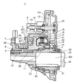
図1はこの発明の第1実施例である湿式多板クラッチ装置1の要部断面を示している。湿式多板クラッチ装置1の入力軸2、すなわち、駆動側の回転部材には、その端部の外周部にスプライン9が設けられ、図示しない原動機の出力軸と接続するための入力フランジ7が係合している。また、装置の出力軸3、すなわち、被動側回転部材は、入力軸2の内側の中空部2aにその端部を挿入し、その中空部2a内の軸受10および11を介して入力軸2を相対回転可能に支持している。そして、ケーシング12は、この入力軸2の外周の軸受13と出力軸3の外周の軸受14により支持されている。したがって、湿式多板クラッチ装置1は、軸受10,11および軸受14により出力軸3に支持されている。
FIG. 1 shows a cross section of the main part of a wet
出力軸3の外周にはスプラインが形成され、スプラインハブ15がスプライン係合によってこの出力軸3と一体に結合されている。そして、このスプラインハブ15には、クラッチ16のインナーディスク17がスプラインハブ15と一体に回転可能であると共に軸方向に移動可能にスプライン係合している。一方、入力軸2には、内周にスプラインを設けたアウターリング18が一体に形成され、このスプラインにはアウターディスク19がアウターリング18と一体に回転可能であると共に軸方向に移動可能にスプライン係合し、前記インナーディスク17と交互に配列されている。なお、インナーディスク17の外周部のアウターディスク19とアウターディスク19の間には、クラッチ16の脱時に押圧部材である作動ピストン5を戻すための戻しばねであるウェブスプリング20が設けられている。また、湿式多板クラッチ装置をトルク伝達制限機構として使用する場合には、各ディスクの材料として、靜摩擦係数と動摩擦係数の数値が近似している摩擦材を用いることにより、滑り出し時のトルクのばらつきを小さくすることができ、制限トルクの精度を向上させることができる。
A spline is formed on the outer periphery of the
クラッチ16の作動ピストン5と反対側には、外周部にアウターリング18の内周のスプラインと噛み合う低歯のスプラインを設けたバックプレート21が設けられ、そのバックプレート21のクラッチ板17,19側はアウターリング18の内周スプラインの段部に当接し、反対側はスナップリングで軸方向の移動がないようにアウターリング18に固定されている。さらに、バックプレート21には、ポンプ駆動ピニオン22が沈頭ボルトで一体に固着されていて、入力軸2と一体に回転すると共にポンプ駆動軸23と一体のポンプ駆動歯車24と噛み合って、油圧ポンプ6を駆動する。
A
入力軸2の軸方向内側には、シールリング25が設置されていて、クラッチ板17、19に押圧力を及ぼす押圧部材である作動ピストン5を作動するクラッチ作動油および潤滑油の漏洩を防止している。油圧ポンプ6から送り出されたクラッチ作動油は、シールカバー26に設けられた作動油ポート27から油路28を経てピストン室29に供給され、作動ピストン5はクラッチ板17,19をバックプレート21に向けて押圧する。一方、潤滑油は、潤滑ポート30から、回転部材2,3やケーシング12に加工された図示されていない油路を経て、クラッチ16の各ディスク(クラッチ板)や軸受等に供給される。
A
出力軸3の外側端部すなわち入力軸2の中空部2aに挿入される側と反対側の端部は、中空部3aが形成され、この中空部3aには、キー31付の被動機軸32の軸端32aが挿入され、テーパブッシュ33をボルト34で締め上げることにより、出力軸3と一体に結合される。なお、テーパブッシュ33には、キー31の幅に相当する切欠溝(図示しない)が設けられている。この場合、出力軸3から被動機軸32へのトルク伝達は、基本的にキー31により行われ、テーパブッシュ33を用いる理由は、その摩擦伝達力によって、クラッチ装置1の軸方向の移動とキー31の側面のたたかれを防止するためである。なお、入力フランジ7および出力軸3が挿入されているケーシング12の軸方向端部と、出力軸3が挿入されている入力軸2の中空部端部には、それぞれオイルシールが設置されていてケーシング12内の潤滑油が外部に漏れるのを防止している。
The outer end of the
図2は、図1のクラッチ装置1を軸と直角方向から見た外観図である。ケーシング12内に組立てられたクラッチ装置1の出力軸3の中空部3aに、被動機軸32を差し込み、テーパブッシュ33で装置1を被動機軸32に固定することによって、装置1の据え付け、芯出し作業は完了する。なお、駆動側の入力フランジ7には、このクラッチ装置1の軸部や軸受に曲げや引っ張りなどの荷重が作用しないように、図示しないたわみ軸継手を介して原動機軸に接続されている。また、ケーシング12には回転止め座37が設けられ、この回転止め座37でクラッチ装置1を床から延長されたブラケットに固定し、振動等によるクラッチ装置1の揺動を防止するものである。また、ブラケットの代わりにリンク式のトルクアームを用いてもよい。
FIG. 2 is an external view of the
ケーシング12の下部には、油溜めが形成されており、油圧ポンプ6により汲み上げられた作動油は、油圧調整弁35に送られて、クラッチ作動油圧および潤滑油圧に調整される。油圧調整弁35には、電磁切換弁36が取り付けられていて、この電磁切換弁36が励磁されると、油圧調整弁35を通ってシールカバー26の作動油ポート27に圧油が導入され、ピストン室29に供給されると同時に、油圧調整弁35の背圧回路にも導入されて、ピストン室29に導入される圧油が潤滑油圧からクラッチ作動油圧に緩やかに昇圧する。なお、循環する作動油は自然冷却されるが、冷却効率を高めるために、入力フランジ7には冷却ファン38を設けることが望ましい。
An oil sump is formed in the lower part of the
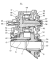
図3は、この発明の第2実施例である湿式多板クラッチ装置41の要部断面図である。図1および図2に示された第1実施例の場合、伝達トルクが大きくなると必然的に駆動側、被動側の軸径が大きくなり、シールリング25の取付部の軸径が大きくなる。湿式多板クラッチ装置の場合、各クラッチ板17,19を押圧する作動油の圧力が高くなるので、高い密封機能を有するシールリング25が使用される。しかしながら、このシールリング25は接触摺動しながらシールするので、シール性能は周速の影響を強く受ける。このため、入力軸である回転部材のシールリング取付部の軸径が所定の大きさより大きくなるときは、図3に示されるこの発明の第2実施例である湿式多板クラッチ装置41が採用される。
FIG. 3 is a cross-sectional view of an essential part of a wet multi-plate
第1実施例と大きく異なる点は、入力軸42の上方にこれと並行に中間軸43を設け、この中間軸43上にクラッチ44を設置し、中間軸43の軸端にシールカバー45を設けて作動油を供給する手段、すなわち押圧力供給手段を構成したものである。このタイプの装置41では、シールリング46をトルク伝達と無関係な軸端部に設けているので、伝達トルク(クラッチ容量)によってシール部の軸径を変化させる必要がなく、かつ、シールリング46の外径を大幅に小さくすることができるので、回転軸の周速の影響を受けにくい。
The main difference from the first embodiment is that an
入力軸42には、入力歯車47がこの軸と一体に形成され、この入力歯車47(この例では歯数56枚に設定)は、中間軸43と一体に形成されたクラッチ歯車48(この例では歯数44枚に設定)に噛み合っていて、入力軸42の回転速度は増速されて、駆動側のクラッチ板に伝達される。中間軸43には、クラッチ44のスプラインハブと一体に形成された中間歯車49(この例ではクラッチ歯車と同じ歯数に設定)が軸受50を介して回転自在に支持されており、この中間歯車49は出力軸51と一体に形成されている出力歯車52(この例では入力歯車と同じ歯数に設定)と噛み合っているので、クラッチ44が結合されると、中間軸43の回転速度は減速されるが、出力軸51には入力軸41と同じ回転速度でトルクが伝達される。なお、必要に応じて、入力軸42と出力軸51の回転速度に差をつけることもできる。
An
クラッチ44の駆動側を増速しているのは、増速することによって、中間軸43における伝達トルクが入力軸42におけるトルクより小さくなり、クラッチ44の容量を小さくすることができるからである。なお、クラッチ容量は伝達トルクだけで決まるものでなく、クラッチ結合時の摩擦によりクラッチディスク(クラッチ板)に発生する熱エネルギを加味して決定されるので、駆動側の増速比はそれらの観点を考慮して総合的に決定されるものである。
The reason why the driving side of the clutch 44 is increased is that the transmission torque in the
中間軸43上には作動ピストン53が設けられていて、図示されていないが、クラッチ44のスプライン部には、第1実施例と同様に、アウターディスクおよびインナーディスクのクラッチ板が交互に配列されている。この例では、第1実施例と異なり、作動ピストン53の戻しばね54がコイルスプリングからなり、クラッチ44のスプラインハブの内側に設けられている。
An
中間軸43の端部には、油圧ポンプ55が設けられ、スプライン係合によって中間軸43から駆動されている。その反対側の軸端には、シールカバー45がケーシング12に固着されている。このシールカバー45には、第1実施例と同様に、作動油ポート57と潤滑油ポート58が設けられ、軸43の溝に嵌められたシールリング46によって作動油の漏洩が防止され、作動ピストン53を押圧するための作動油が油路を経てピストン室59に供給される。
A
シールカバー45の中央部には潤滑油ポート58が設けられ、カバー45の内側と中間軸43の端面との間の空間から、ケーシング12に形成された油路を経て各部に必要な潤滑油が供給される。また、この潤滑油は中間軸43に設けた油路を経由してクラッチ44にも供給される。なお、これ以外の構造は第1実施例と基本的に同じである。
A lubricating
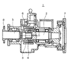
図4は、図1の示された湿式多板クラッチ装置1において原動機軸62と被動機軸の取り付けを逆にした第3実施例のクラッチ装置61の要部を示している。油圧ポンプ6は、クラッチ16が遮断された状態においても、駆動されて潤滑油を供給する必要があるため、油圧ポンプ6の駆動は常に原動機軸側から行う必要がある。
FIG. 4 shows a main part of the
ところで、クラッチ装置を原動機軸と被動機軸の何れの側にも取り付け可能にするのは、原動機や被動機の種類、設置される設備の種類等に応じて使い分けできるようにするためである。例えば、試運転用の設備に設置する場合などでは、負荷側(被動機側)に接続された試験機を頻繁に交換する必要があるので、クラッチ装置は原動機軸に取り付けて使用する方が合理的であり、また、原動機がガスタービンなど高速で回転するものの場合は、振動の影響を受けることの少ない被動機軸側に取り付けて使用することなどが考えられる。 By the way, the reason why the clutch device can be attached to either side of the prime mover shaft or the driven machine shaft is to enable the clutch device to be selectively used according to the kind of the prime mover or the driven machine, the kind of installed equipment, or the like. For example, when installing in a facility for trial operation, it is necessary to frequently replace the test machine connected to the load side (driven machine side), so it is more reasonable to use the clutch device attached to the motor shaft. In addition, in the case where the prime mover rotates at a high speed such as a gas turbine, it can be considered that the prime mover is attached to the driven machine shaft side which is less affected by vibration.
図4に示される例は、出力軸3を原動機軸62に結合、すなわち、接続して使用する場合であり、この場合、ポンプ駆動ピニオン22aはバックプレート21aから切り離され、スプラインハブ15aに一体に固定され、ポンプ駆動ギヤ24に噛み合っている。第1実施例とは、駆動ピニオン22a、バックプレート21aおよびスプラインハブ15aが異なっているが、その他の構成は同じであり、ケーシング12の形状を変更することなく、クラッチ装置を原動機軸62に取り付けることができる。
The example shown in FIG. 4 is a case where the
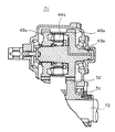
図5は、この発明の第4実施例であるクラッチ装置71の要部断面を示し、図3に示された第2実施例の出力軸51を原動機軸72に結合、すなわち、接続して使用する場合である。この場合には、中間軸43a上のクラッチ歯車48a、中間歯車49aおよびクラッチ44aを図3に示される状態から反転させた形で配置したものである。
FIG. 5 is a cross-sectional view of a main part of a
1、41、61、71 クラッチ装置
2 入力軸
2a 中空部
3 出力軸
3a 中空部
4、16、44、44a クラッチ
5、53 作動ピストン
6 油圧ポンプ
7 入力フランジ
8 出力フランジ
10、11 軸受
13、14 軸受
21 バックプレート
24 ポンプ駆動歯車
25 シールリング
29、59 ピストン室
31 キー
32 被動機軸
33 テーパブッシュ
34 ボルト
35 油圧調整弁
37 回転止め座
38 冷却ファン
43、43a 中間軸
DESCRIPTION OF
Claims (5)
Priority Applications (1)
| Application Number | Priority Date | Filing Date | Title |
|---|---|---|---|
| JP2004113244A JP2005299729A (en) | 2004-04-07 | 2004-04-07 | Wet multi-plate clutch device |
Applications Claiming Priority (1)
| Application Number | Priority Date | Filing Date | Title |
|---|---|---|---|
| JP2004113244A JP2005299729A (en) | 2004-04-07 | 2004-04-07 | Wet multi-plate clutch device |
Publications (1)
| Publication Number | Publication Date |
|---|---|
| JP2005299729A true JP2005299729A (en) | 2005-10-27 |
Family
ID=35331510
Family Applications (1)
| Application Number | Title | Priority Date | Filing Date |
|---|---|---|---|
| JP2004113244A Pending JP2005299729A (en) | 2004-04-07 | 2004-04-07 | Wet multi-plate clutch device |
Country Status (1)
| Country | Link |
|---|---|
| JP (1) | JP2005299729A (en) |
Cited By (1)
| Publication number | Priority date | Publication date | Assignee | Title |
|---|---|---|---|---|
| CN103562582A (en) * | 2011-06-16 | 2014-02-05 | 本田技研工业株式会社 | Clutch for transmission |
-
2004
- 2004-04-07 JP JP2004113244A patent/JP2005299729A/en active Pending
Cited By (2)
| Publication number | Priority date | Publication date | Assignee | Title |
|---|---|---|---|---|
| CN103562582A (en) * | 2011-06-16 | 2014-02-05 | 本田技研工业株式会社 | Clutch for transmission |
| CN103562582B (en) * | 2011-06-16 | 2014-11-05 | 本田技研工业株式会社 | Clutch for transmission |
Similar Documents
| Publication | Publication Date | Title |
|---|---|---|
| JP4915002B2 (en) | Torque transmission device and drive train equipped with the torque transmission device | |
| JP4961188B2 (en) | Double clutch | |
| US6305515B1 (en) | Hydraulically actuated power takeoff clutch assembly | |
| JP5025249B2 (en) | Starting clutch | |
| JP5235885B2 (en) | Pump drive gear support structure on the drive side in off-axis pump arrangement structure in automatic transmission | |
| CN103906940B (en) | Driving force transfer unit | |
| JP2005527758A (en) | Speed change transmission for automobiles with multiple clutches operable by hydraulic pressure | |
| JP2007062726A (en) | Hybrid vehicle power transmission system | |
| JPS63285342A (en) | Clutch-brake gear | |
| WO2010021243A1 (en) | Torque converter | |
| KR19980084754A (en) | Wet Friction Plates, Wet Power Train / Isolator, Wet Clutch and Lock-Up Clutch | |
| EP2390533B1 (en) | Power transmission device | |
| CN111287762B (en) | Motor-gear unit, in particular for a tunnel boring machine or for driving a toothed ring | |
| US20090118072A1 (en) | Generator shear gear | |
| JP4770625B2 (en) | Automatic transmission | |
| US7891179B2 (en) | Radially compliant pump hub | |
| EP1148275B1 (en) | Transmission for industrial vehicles with two hydrostatic control motors | |
| US8387729B2 (en) | Machine having electrical power system and centered drive coupling for same | |
| JP2005299729A (en) | Wet multi-plate clutch device | |
| US20080148883A1 (en) | Power Take-Off for Industrial Vehicles | |
| JP2005098409A (en) | Clutch device | |
| KR102519195B1 (en) | Limited slip differential for vehicles and electric drive apparatus including same | |
| JP2011106557A (en) | Torque converter device | |
| JP4605495B2 (en) | Toroidal continuously variable transmission | |
| JP2001099186A (en) | Clutch structure |
Legal Events
| Date | Code | Title | Description |
|---|---|---|---|
| A621 | Written request for application examination |
Free format text: JAPANESE INTERMEDIATE CODE: A621 Effective date: 20060221 |
|
| A977 | Report on retrieval |
Free format text: JAPANESE INTERMEDIATE CODE: A971007 Effective date: 20081211 |
|
| A131 | Notification of reasons for refusal |
Free format text: JAPANESE INTERMEDIATE CODE: A131 Effective date: 20090512 |
|
| A521 | Written amendment |
Free format text: JAPANESE INTERMEDIATE CODE: A523 Effective date: 20090702 |
|
| A02 | Decision of refusal |
Free format text: JAPANESE INTERMEDIATE CODE: A02 Effective date: 20091201 |