JP2005299699A - Hydraulic control device - Google Patents
Hydraulic control device Download PDFInfo
- Publication number
- JP2005299699A JP2005299699A JP2004112242A JP2004112242A JP2005299699A JP 2005299699 A JP2005299699 A JP 2005299699A JP 2004112242 A JP2004112242 A JP 2004112242A JP 2004112242 A JP2004112242 A JP 2004112242A JP 2005299699 A JP2005299699 A JP 2005299699A
- Authority
- JP
- Japan
- Prior art keywords
- pressure
- hydraulic
- temperature
- regulator valve
- control device
- Prior art date
- Legal status (The legal status is an assumption and is not a legal conclusion. Google has not performed a legal analysis and makes no representation as to the accuracy of the status listed.)
- Pending
Links
Images

Landscapes
- Control Of Transmission Device (AREA)
Abstract
【課題】 所定の供給対象に供給されるべき作動液の温度を効率よく良好に上昇させることができる液圧制御装置の提供。
【解決手段】 液圧制御装置1は、オイルポンプ2から無段変速機10に供給される作動油の圧力PLを設定する高圧レギュレータ弁3と、オイルポンプ2から高圧レギュレータ弁3を介してトルクコンバータ20に供給される作動油の圧力PSを設定する低圧レギュレータ弁4と、作動油の温度TFを取得するための温度センサ6と、温度センサ6を用いて取得される温度TFが所定値TRを下回っている場合に、無段変速機10に供給される作動油の圧力PLが高まるように高圧レギュレータ弁3を制御すると共に、トルクコンバータ20に供給される作動油の圧力PSが低下するように低圧レギュレータ弁4を制御するコントローラ7とを備える。
【選択図】 図1
PROBLEM TO BE SOLVED: To provide a hydraulic pressure control device capable of efficiently and satisfactorily increasing the temperature of hydraulic fluid to be supplied to a predetermined supply target.
A fluid pressure control device 1 includes a high-pressure regulator valve 3 for setting the pressure P L of the hydraulic oil supplied from the oil pump 2 to the continuously variable transmission 10, through the high-pressure regulator valve 3 from the oil pump 2 a low-pressure regulator valve 4 to set the pressure P S of the hydraulic oil supplied to the torque converter 20, a temperature sensor 6 for acquiring the temperature T F of the hydraulic oil, the temperature T F which is acquired using a temperature sensor 6 If There is below a predetermined value T R, and controls the high-pressure regulator valve 3 so that the pressure P L increases of hydraulic oil supplied to the continuously variable transmission 10, the hydraulic oil supplied to the torque converter 20 and a controller 7 which pressure P S controls the low-pressure regulator valve 4 to decrease.
[Selection] Figure 1
Description
本発明は、液圧制御装置に関し、特に、液圧発生源から第1および第2の供給対象に供給される作動液の圧力を調整する液圧制御装置に関する。 The present invention relates to a hydraulic pressure control device, and more particularly to a hydraulic pressure control device that adjusts the pressure of hydraulic fluid supplied from a hydraulic pressure generation source to first and second supply targets.
一般に、自動変速機等の液圧ユニットやトルクコンバータでは、作動液の粘度が高まることに起因して、低温時の動作がスムースに実行されないことがある。このため、従来から、自動変速機の作動液の温度が所定値以下となる間、クラッチやブレーキをスムースに作動させるべく、作動液圧(ライン圧)を高める技術が知られている(例えば、特許文献1および2参照。)。また、低温時に自動変速機をスムースに作動させるべく、自動変速機用の作動液とエンジン冷却水とを熱交換させて作動液を昇温させる技術も知られている(例えば、特許文献3参照。)。
Generally, in a hydraulic unit such as an automatic transmission or a torque converter, an operation at a low temperature may not be smoothly executed due to an increase in the viscosity of hydraulic fluid. For this reason, conventionally, there has been known a technique for increasing the hydraulic fluid pressure (line pressure) in order to smoothly operate the clutch and the brake while the temperature of the hydraulic fluid in the automatic transmission is a predetermined value or less (for example, (See
しかしながら、自動変速機のクラッチやブレーキ等に供給される作動液の圧力を高めただけでは、これらの要素の低温時の動作をスムースに実行させることは困難であった。また、自動変速機の作動液とエンジン冷却水とを熱交換させても作動液を良好に昇温させることは困難であった。 However, it has been difficult to smoothly perform the operation of these elements at a low temperature only by increasing the pressure of the hydraulic fluid supplied to the clutch, brake, etc. of the automatic transmission. Further, it is difficult to raise the temperature of the hydraulic fluid satisfactorily even if the hydraulic fluid of the automatic transmission and the engine cooling water are subjected to heat exchange.
そこで、本発明は、所定の供給対象に供給されるべき作動液の温度を効率よく良好に上昇させることができる液圧制御装置の提供を目的とする。 Accordingly, an object of the present invention is to provide a hydraulic pressure control device that can efficiently and satisfactorily increase the temperature of hydraulic fluid to be supplied to a predetermined supply target.
本発明による液圧制御装置は、液圧発生源から第1および第2の供給対象に供給される作動液の圧力を調整する液圧制御装置において、液圧発生源から第1の供給対象に供給される作動液の圧力を設定する第1の圧力調整手段と、液圧発生源から第1の圧力調整手段を介して第2の供給対象に供給される作動液の圧力を設定する第2の圧力調整手段と、所定箇所における作動液の温度を取得するための温度検出手段と、温度検出手段を用いて取得される温度が所定値を下回っている場合に、第2の供給対象に供給される作動液の圧力が低下するように第2の圧力調整手段を制御する制御手段とを備えることを特徴とする。 A hydraulic pressure control device according to the present invention is a hydraulic pressure control device that adjusts the pressure of hydraulic fluid supplied from a hydraulic pressure generation source to first and second supply targets, and from the hydraulic pressure generation source to the first supply target. A first pressure adjusting means for setting the pressure of the hydraulic fluid to be supplied; and a second pressure for setting the pressure of the hydraulic fluid to be supplied to the second supply target from the hydraulic pressure generation source via the first pressure adjusting means. Pressure adjusting means, temperature detecting means for acquiring the temperature of the hydraulic fluid at a predetermined location, and supply to the second supply object when the temperature acquired using the temperature detecting means is below a predetermined value And control means for controlling the second pressure adjusting means so that the pressure of the hydraulic fluid to be reduced is reduced.
この液圧制御装置では、液圧発生源からの作動液が第1の圧力調整手段によって調圧された上で第1の供給対象に供給され、第1の圧力調整手段からの作動液が第2の圧力調整手段によって調圧された上で第2の供給対象に供給される。この場合、作動液には、第1の圧力調整手段の前後において、第1の圧力調整手段による設定圧と第2の圧力調整手段による設定圧との差圧に応じた熱量が付与されることになる。従って、第2の供給対象に供給される作動液の圧力(第2の圧力調整手段による設定圧)が低下するように第2の圧力調整手段を制御すれば、第1の圧力調整手段の前後における作動液の差圧を大きくすることができるので、第1の圧力調整手段の前後で作動液に対して多くの熱量を付与することが可能となる。この結果、この液圧制御装置によれば、温度検出手段を用いて取得される所定箇所における作動液の温度が所定値を下回る低温時に、第2の供給対象に供給されるべき作動液の温度を効率よく良好に上昇させることが可能となる。 In this hydraulic pressure control device, the hydraulic fluid from the hydraulic pressure generation source is regulated by the first pressure adjusting means and then supplied to the first supply target, and the hydraulic fluid from the first pressure regulating means is supplied to the first pressure regulating means. The pressure is adjusted by the second pressure adjusting means and then supplied to the second supply target. In this case, the amount of heat corresponding to the pressure difference between the set pressure by the first pressure adjusting means and the set pressure by the second pressure adjusting means is applied to the hydraulic fluid before and after the first pressure adjusting means. become. Therefore, if the second pressure adjusting means is controlled so that the pressure of the hydraulic fluid supplied to the second supply target (the set pressure by the second pressure adjusting means) is reduced, before and after the first pressure adjusting means. Since the differential pressure of the hydraulic fluid at can be increased, a large amount of heat can be imparted to the hydraulic fluid before and after the first pressure adjusting means. As a result, according to this hydraulic pressure control device, the temperature of the hydraulic fluid to be supplied to the second supply target at a low temperature when the temperature of the hydraulic fluid at the predetermined location acquired using the temperature detecting means is lower than a predetermined value. Can be raised efficiently and satisfactorily.
また、制御手段は、温度検出手段を用いて取得される温度が所定値を下回っている場合に、第1の供給対象に供給される作動液の圧力が高まるように第1の圧力調整手段を制御すると好ましい。 Further, the control means sets the first pressure adjusting means so that the pressure of the hydraulic fluid supplied to the first supply target is increased when the temperature acquired using the temperature detecting means is below a predetermined value. Control is preferred.
このような構成を採用すれば、第1の圧力調整手段の前後における作動液の差圧をより大きくすることができるので、第1の圧力調整手段の前後で作動液に対して付与される熱量をより一層増加させることが可能となる。 By adopting such a configuration, the differential pressure of the hydraulic fluid before and after the first pressure adjusting means can be increased, so the amount of heat applied to the hydraulic fluid before and after the first pressure adjusting means. Can be further increased.
そして、第1の供給対象には、少なくとも車両用変速機の液圧ユニットが含まれ、第2の供給対象には、トルクコンバータおよび所定の潤滑系統の少なくとも何れかが含まれると好ましい。 Preferably, the first supply target includes at least a hydraulic unit of the vehicle transmission, and the second supply target includes at least one of a torque converter and a predetermined lubrication system.
本発明によれば、所定の供給対象に供給されるべき作動液の温度を効率よく良好に上昇させることができる液圧制御装置の実現が可能となる。 According to the present invention, it is possible to realize a hydraulic pressure control device that can efficiently and satisfactorily increase the temperature of hydraulic fluid to be supplied to a predetermined supply target.
以下、図面を参照しながら、本発明を実施するための最良の形態について詳細に説明する。 Hereinafter, the best mode for carrying out the present invention will be described in detail with reference to the drawings.
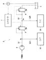
図1は、本発明による液圧制御装置を示す系統図である。同図に示される液圧制御装置1は、図示されない車両の油圧系統に組み込まれるものである。液圧制御装置1は、図1に示されるように、油路L1を介してオイルポンプ2に接続された高圧レギュレータ弁(第1の圧力調整手段)3と、油路L2を介して高圧レギュレータ弁3に接続された低圧レギュレータ弁(第2の圧力調整手段)4とを含む。高圧レギュレータ弁3は、油路L1における作動油の圧力(ライン圧)PLを設定するものであり、低圧レギュレータ弁4は、油路L2における作動油の圧力(セカンダリ圧)PSを設定するものである。
FIG. 1 is a system diagram showing a hydraulic control apparatus according to the present invention. A hydraulic
また、油路L1からは、オイルポンプ2と高圧レギュレータ弁3との間の分岐部において油路L10が分岐されており、この油路L10を介して、第1の供給対象であるベルト式無段変速機(CVT)10のクラッチ機構、ブレーキ機構、プライマリプーリの溝幅を変化させるための油圧アクチュエータ、セカンダリプーリの溝幅を変化させるための油圧アクチュエータといった液圧ユニットに対して作動油が供給される。また、油路L2からは、高圧レギュレータ弁3と低圧レギュレータ弁4との間の分岐部において油路L20が分岐されており、この油路L20を介して、第2の供給対象であるトルクコンバータ20に対して作動油が供給される。
Further, an oil passage L10 is branched from the oil passage L1 at a branch portion between the
更に、液圧制御装置1は、オイルパン5に配置された温度センサ6と、制御手段としてのコントローラ7とを含む。温度センサ6は、オイルパン5内の作動油の温度を検出し、検出値を示す信号をコントローラ7に与える。なお、温度センサ6は、第2の供給対象であるトルクコンバータ20に対して設置されてもよく、トルクコンバータ20における作動油の温度に基づいて以下の制御が実行されてもよい。また、作動油の温度は、必ずしも温度センサによって直接計測される必要はなく、車両の走行パターンや作動油の粘度等から推定されてもよい。そして、コントローラ7は、CPU、ROM、RAM、入出力ポート、および、各種情報やマップ等が記憶されるメモリを含む。このコントローラ7の入出力ポートには、上述の高圧レギュレータ弁3のアクチュエータ部と、低圧レギュレータ弁4のアクチュエータ部とが接続されている。コントローラ7は、温度センサ6や図示されない他のセンサ等の検出値に応じて、高圧レギュレータ弁3および低圧レギュレータ弁4を制御する。
Furthermore, the hydraulic
上述のように構成される液圧制御装置1では、オイルポンプ2からの作動油がコントローラ7によって制御される高圧レギュレータ弁3によって調圧された上で第1の供給対象である無段変速機10(クラッチ機構、ブレーキ機構、各油圧アクチュエータ)に供給される。また、高圧レギュレータ弁3による作動油の圧力調整(ライン圧調整)により余剰となった作動油は、高圧レギュレータ弁3から油路L2へと流れ込み、コントローラ7によって制御される低圧レギュレータ弁4によって調圧された上で第2の供給対象であるトルクコンバータ20に供給されることになる。
In the hydraulic
ところで、車両の始動開始直後や周囲温度が低い場合等の低温時には、作動油の粘度が高まることに起因して、液圧制御装置1によって調圧された作動油が供給されるトルクコンバータ20の動作がスムースに実行されないこともあり得る。この点に鑑みて、上述の液圧制御装置1では、トルクコンバータ20を常時良好に作動させるために、車両の運転中、コントローラ7によって図2に示されるルーチンが繰り返し実行される。
By the way, the torque converter 20 to which the hydraulic oil regulated by the hydraulic
すなわち、コントローラ7は、車両運転中の例えば所定時間おきに、温度センサ6からの信号に基づいて作動油の温度TFを取得し(S10)、取得した温度TFが予め定められた閾値TRを下回っているか否か判定している(S12)。そして、コントローラ7は、S12にて、作動油の温度TFが予め定められた閾値TRを下回っていると判断した場合、油路L1における作動油の圧力(ライン圧)、すなわち、無段変速機10に供給される作動油の圧力PLが所定値だけ高まるように高圧レギュレータ弁3を制御すると共に、油路L2における作動油の圧力(セカンダリ圧)、すなわち、高圧レギュレータ弁3を介してトルクコンバータ20に供給される作動油の圧力PSが所定値だけ低下するように低圧レギュレータ弁4を制御する(S14)。
That is, the controller 7 acquires the temperature TF of the hydraulic oil based on a signal from the
ここで、上述のように、高圧レギュレータ弁3と低圧レギュレータ弁4とによる作動油の調圧が実行されている場合、高圧レギュレータ弁3を通過して油路L2に流れ込む作動油の流量をQとすると、作動油には、高圧レギュレータ弁3の前後において、高圧レギュレータ弁3による設定圧PLと低圧レギュレータ弁による設定圧PSとの差圧に応じた熱量:Q×(PL−PS)が付与されることになる。従って、少なくとも、オイルポンプ2から高圧レギュレータ弁3を介してトルクコンバータ20(第2の供給対象)に供給される作動油の圧力(低圧レギュレータ弁4による設定圧)PSが低下するように低圧レギュレータ弁4を制御すれば、高圧レギュレータ弁3の前後における作動油の差圧(PL−PS)を大きくすることができる。 Here, as described above, when the hydraulic oil is regulated by the high-pressure regulator valve 3 and the low-pressure regulator valve 4, the flow rate of the hydraulic oil flowing into the oil passage L <b> 2 through the high-pressure regulator valve 3 is defined as Q. When, the hydraulic fluid before and after the high-pressure regulator valve 3, the amount of heat corresponding to the pressure difference between the set pressure P S by setting by the high-pressure regulator valve 3 pressure P L and the low pressure regulator valve: Q × (P L -P S ). Accordingly, at least, as from the oil pump 2 (set by the low-pressure regulator valve 4 pressure) torque converter 20 (second supply target) to the supplied hydraulic oil pressure via a high-pressure regulator valve 3 P S drops low If the regulator valve 4 is controlled, the hydraulic oil differential pressure (P L -P S ) before and after the high pressure regulator valve 3 can be increased.
また、S14では、更に無段変速機10(第1の供給対象)に供給される作動油の圧力(高圧レギュレータ弁3による設定圧)PLが高まるように高圧レギュレータ弁3が制御されることから、高圧レギュレータ弁3の前後における作動油の差圧(PL−PS)をより一層大きくすることができる。従って、液圧制御装置1では、高圧レギュレータ弁3にて作動油に対して多くの熱量を確実に付与することが可能となる。
Also, S14 in further that the continuously variable transmission 10 (first supply target) pressure of hydraulic fluid supplied to the (high-pressure regulator valve 3 by setting pressure) P L is increased so that the high-pressure regulator valve 3 is controlled Therefore, the differential pressure (P L −P S ) of the hydraulic oil before and after the high pressure regulator valve 3 can be further increased. Therefore, in the
この結果、液圧制御装置1によれば、温度センサ6を用いて取得される作動油の温度TFが所定値TRを下回る低温時に、油路L2およびL20を介してトルクコンバータ20に供給される作動油の温度を効率よく良好に上昇させることが可能となる。従って、液圧制御装置1を用いれば、トルクコンバータ20を早期に暖機することが可能となり、いわゆる引き摺り損失を早期に低減させると共に、ロックアップクラッチの滑り特性や流体継手としての特性を早期に適正化することができる。
As a result, according to the
なお、S12にて作動油の温度TFが閾値TRを下回っていないと判断される場合には、予め定められた手順に従って通常のバルブ制御が実行されることになる(S16)。また、オイルポンプ2から高圧レギュレータ弁3を介して作動油が供給される第2の供給対象は、トルクコンバータに限られるものではなく、第2の供給対象として、各種クラッチ機構の摩擦部材の潤滑するための潤滑系統が選択されてもよい。このように、液圧制御装置1によって潤滑系統に供給される作動液の圧力を調整すれば、クラッチ機構の早期暖機が可能となり、クラッチ摩擦部材の引き摺り損失を早期に低減させると共に、クラッチ機構におけるオイルレベルを適正化することが可能となる。もちろん、第2の供給対象として、トルクコンバータと所定の潤滑系統との双方を選択し得ることはいうまでもない。
The temperature T F of the hydraulic oil when it is determined that not lower than the threshold value T R is, the normal valve control according to a predetermined procedure is executed at S12 (S16). Further, the second supply target to which the hydraulic oil is supplied from the
1 液圧制御装置
2 オイルポンプ
3 高圧レギュレータ弁
4 低圧レギュレータ弁
5 オイルパン
6 温度センサ
7 コントローラ
10 無段変速機
20 トルクコンバータ
L1,L2,L10,L20 油路
DESCRIPTION OF
Claims (3)
前記液圧発生源から前記第1の供給対象に供給される作動液の圧力を設定する第1の圧力調整手段と、
前記液圧発生源から前記第1の圧力調整手段を介して前記第2の供給対象に供給される作動液の圧力を設定する第2の圧力調整手段と、
所定箇所における作動液の温度を取得するための温度検出手段と、
前記温度検出手段を用いて取得される温度が所定値を下回っている場合に、前記第2の供給対象に供給される作動液の圧力が低下するように前記第2の圧力調整手段を制御する制御手段とを備えることを特徴とする液圧制御装置。 In a hydraulic pressure control device that adjusts the pressure of hydraulic fluid supplied from the hydraulic pressure generation source to the first and second supply targets,
First pressure adjusting means for setting the pressure of hydraulic fluid supplied from the hydraulic pressure generation source to the first supply target;
Second pressure adjusting means for setting a pressure of hydraulic fluid supplied from the fluid pressure generation source to the second supply object via the first pressure adjusting means;
Temperature detecting means for acquiring the temperature of the hydraulic fluid at a predetermined location;
When the temperature acquired using the temperature detecting means is below a predetermined value, the second pressure adjusting means is controlled so that the pressure of the hydraulic fluid supplied to the second supply target is reduced. A hydraulic control device comprising a control means.
Priority Applications (1)
| Application Number | Priority Date | Filing Date | Title |
|---|---|---|---|
| JP2004112242A JP2005299699A (en) | 2004-04-06 | 2004-04-06 | Hydraulic control device |
Applications Claiming Priority (1)
| Application Number | Priority Date | Filing Date | Title |
|---|---|---|---|
| JP2004112242A JP2005299699A (en) | 2004-04-06 | 2004-04-06 | Hydraulic control device |
Publications (1)
| Publication Number | Publication Date |
|---|---|
| JP2005299699A true JP2005299699A (en) | 2005-10-27 |
Family
ID=35331484
Family Applications (1)
| Application Number | Title | Priority Date | Filing Date |
|---|---|---|---|
| JP2004112242A Pending JP2005299699A (en) | 2004-04-06 | 2004-04-06 | Hydraulic control device |
Country Status (1)
| Country | Link |
|---|---|
| JP (1) | JP2005299699A (en) |
Cited By (1)
| Publication number | Priority date | Publication date | Assignee | Title |
|---|---|---|---|---|
| WO2015025602A1 (en) * | 2013-08-20 | 2015-02-26 | 株式会社小松製作所 | Working vehicle |
-
2004
- 2004-04-06 JP JP2004112242A patent/JP2005299699A/en active Pending
Cited By (4)
| Publication number | Priority date | Publication date | Assignee | Title |
|---|---|---|---|---|
| WO2015025602A1 (en) * | 2013-08-20 | 2015-02-26 | 株式会社小松製作所 | Working vehicle |
| CN105659003A (en) * | 2013-08-20 | 2016-06-08 | 株式会社小松制作所 | Working vehicle |
| US9625033B2 (en) | 2013-08-20 | 2017-04-18 | Komatsu Ltd. | Work vehicle |
| CN105659003B (en) * | 2013-08-20 | 2017-07-21 | 株式会社小松制作所 | Working truck |
Similar Documents
| Publication | Publication Date | Title |
|---|---|---|
| CN101765731B (en) | Fault judging device and fault judging method for continuously variable transmission | |
| JP4605245B2 (en) | Hydraulic control device | |
| US9133929B2 (en) | Main modulation calibration using control main valve | |
| US6077187A (en) | Electronic transmission control system with fail-safe system for automotive vehicle with continuously variable automatic transmission | |
| US20040063523A1 (en) | System and method of controlling automatic transmission | |
| EP1878952A3 (en) | Shift control system and shift control method for continuously variable transmission | |
| CN105074288B (en) | Variator control circuit | |
| JP2018040422A (en) | Control device for continuously variable transmission | |
| EP1403563B1 (en) | Control for belt-type continuously-variable transmission | |
| JP4939915B2 (en) | Control device for continuously variable transmission | |
| CN104204624B (en) | Oil pressure control circuit and control method thereof | |
| EP1498643A2 (en) | Hydraulic transmission control system and method for vehicle having automatic engine stop/restart function | |
| US8437932B2 (en) | Main modulation calibration using clutch trim valve | |
| JP2005299699A (en) | Hydraulic control device | |
| JP4274807B2 (en) | Automatic transmission control device | |
| JP4396247B2 (en) | Hydraulic control device for belt type continuously variable transmission | |
| JP2009270690A (en) | Oil pressure control device for vehicular continuously variable transmission | |
| US6418366B1 (en) | Method for ratio controlling or speed controlling | |
| CN100476248C (en) | Hydraulic controller for belt driving stepless speed variator and control method thereof | |
| KR100398215B1 (en) | Devise and the method for shift controlling of auto transmission in vehicle | |
| KR100345130B1 (en) | Method for line pressure controlling of automatic transmission of vehicle | |
| KR100534774B1 (en) | Method of controlling shift of an automatic transmission for vehicles | |
| JP4882609B2 (en) | Shift control device for belt type continuously variable transmission | |
| JP2010265918A (en) | Control device and control method for continuously variable transmission | |
| US9008921B2 (en) | Pressure regulation method for an automatic transmission |