JP2005299645A - Axial-flow piston hydraulic power unit with false slipper - Google Patents
Axial-flow piston hydraulic power unit with false slipper Download PDFInfo
- Publication number
- JP2005299645A JP2005299645A JP2005090563A JP2005090563A JP2005299645A JP 2005299645 A JP2005299645 A JP 2005299645A JP 2005090563 A JP2005090563 A JP 2005090563A JP 2005090563 A JP2005090563 A JP 2005090563A JP 2005299645 A JP2005299645 A JP 2005299645A
- Authority
- JP
- Japan
- Prior art keywords
- slipper
- piston
- axial
- pump
- piston pump
- Prior art date
- Legal status (The legal status is an assumption and is not a legal conclusion. Google has not performed a legal analysis and makes no representation as to the accuracy of the status listed.)
- Pending
Links
Images

Classifications
-
- F—MECHANICAL ENGINEERING; LIGHTING; HEATING; WEAPONS; BLASTING
- F04—POSITIVE - DISPLACEMENT MACHINES FOR LIQUIDS; PUMPS FOR LIQUIDS OR ELASTIC FLUIDS
- F04B—POSITIVE-DISPLACEMENT MACHINES FOR LIQUIDS; PUMPS
- F04B1/00—Multi-cylinder machines or pumps characterised by number or arrangement of cylinders
- F04B1/12—Multi-cylinder machines or pumps characterised by number or arrangement of cylinders having cylinder axes coaxial with, or parallel or inclined to, main shaft axis
- F04B1/122—Details or component parts, e.g. valves, sealings or lubrication means
- F04B1/124—Pistons
- F04B1/126—Piston shoe retaining means
Landscapes
- Engineering & Computer Science (AREA)
- Mechanical Engineering (AREA)
- General Engineering & Computer Science (AREA)
- Reciprocating Pumps (AREA)
Abstract
Description
本発明は、疑似スリッパーを備えた軸流ピストン液圧動力ユニットに関する。 The present invention relates to an axial piston hydraulic power unit having a pseudo slipper.
従来、いくつかの異なるタイプの軸流ピストン液圧ポンプが知られている。例えば、スリッパータイプの軸流ピストンポンプが知られている。このタイプの軸流ピストンポンプは、スリッパーのベアリングに係合する一端に、ほぼ球形のボールを備えるピストン本体を有している。このスリッパータイプの軸流ピストンポンプの利点は、ポンプの寿命が長く、頑丈であり、かつ極めて耐久性があるということにある。また、ピストン内部における接触応力も小さい。 Conventionally, several different types of axial piston hydraulic pumps are known. For example, a slipper type axial piston pump is known. This type of axial piston pump has a piston body with a generally spherical ball at one end that engages a slipper bearing. The advantage of this slipper type axial piston pump is that the pump has a long life, is robust and extremely durable. Also, the contact stress inside the piston is small.
このタイプの軸流ピストンポンプは、これらの点では有利であるが、多数の複雑な部品から成るスリッパーホルードダウン機構を有し、かつ部品数が多いという欠点を有する。更に静水圧バランスを保つために、ピストンおよびスリッパーにオリフィスを開けなければならず、その作動に極めて費用がかかる。また、このオリフィスによって、ポンプ内のオイルが失われるので、効率が低下する。スリッパータイプのピストンは、質量が比較的大きく、この質量体は、ポンプが回転するごとに、シリンダボア内で往復動しなければならない。 This type of axial piston pump is advantageous in these respects, but has the disadvantage that it has a slipper holddown mechanism composed of a large number of complicated parts and has a large number of parts. Furthermore, to maintain the hydrostatic pressure balance, orifices must be opened in the piston and slipper, which is very expensive to operate. This orifice also loses oil in the pump, reducing efficiency. A slipper type piston has a relatively large mass, and this mass must reciprocate within the cylinder bore each time the pump rotates.
別のタイプの軸流ピストンポンプは、ブルノーズタイプの軸流ピストンポンプである。このブルノーズタイプのピストンポンプは、中空ピストン本体を有し、この中空ピストン本体の内部には、ピストンを下方に保持するためのスプリングが配置されており、ピストンの端部はレース要素に係合し、このレース要素の間に、ボールスラストベアリングが設けられている。 Another type of axial piston pump is a bull nose type axial piston pump. This bull nose type piston pump has a hollow piston body, and a spring for holding the piston downward is arranged inside the hollow piston body, and the end of the piston engages with a race element. A ball thrust bearing is provided between the race elements.
ブルノーズタイプ構造は、スリッパーを有しないので、製造が簡単であり、かつ極めて安価である。しかし、ピストンのブルノーズ端部は、スラストベアリングのレースに点接触し、この点接触部には、大きい荷重が伝えられるので、接触応力が大きくなる。この大きい接触応力によって、ブルノーズピストンの用途は、寿命が比較的短い低動力ユニットに制限されている The bull nose type structure does not have a slipper, so it is easy to manufacture and is very inexpensive. However, the bull nose end portion of the piston makes point contact with the race of the thrust bearing, and a large load is transmitted to the point contact portion, so that the contact stress increases. This large contact stress limits the use of bull nose pistons to low power units that have a relatively short life.
現在、当技術分野では、スリッパータイプの軸流ピストンポンプには、精密に機械加工されて、スリッパーの製造コストが高いということだけでなく、ピストン本体の製造コストも高いという問題がある。 Currently, the slipper-type axial flow piston pump has a problem that not only is it machined precisely and the manufacturing cost of the slipper is high, but also the manufacturing cost of the piston body is high.
スリッパーが走行する静水圧オイル膜を形成する際に、流体の損失が生じ、かつ、スリッパーの質量が大きいため、回転速度が制限され、効率が低いという問題もある。他方、ブルノーズタイプのピストンポンプは、圧力、押しのけ量、および寿命が制限されている。これらの実用上の制限のために、ブルノーズピストンポンプの広範な普及が妨げられている。 When forming a hydrostatic oil film on which the slipper travels, there is a problem that fluid loss occurs and the slipper mass is large, so that the rotational speed is limited and the efficiency is low. On the other hand, bull nose type piston pumps have limited pressure, displacement and life. These practical limitations prevent the widespread use of bull nose piston pumps.
従って、どのタイプのピストンが使用されているかにかかわらず、メーカーは、ポンプの寿命、またはポンプのコストのいずれかにおける欠点に悩んでいる。 Therefore, regardless of what type of piston is used, manufacturers suffer from shortcomings in either pump life or pump cost.
従って、当技術分野では、従来技術における欠点を克服した軸流ピストンポンプを提供しうるよう、スリッパータイプの軸流ピストンポンプの要素と、ブルノーズタイプの軸流ピストンポンプの要素とを組み合わせた軸流ピストンポンプが求められている。 Therefore, in this technical field, a slipper type axial piston pump element and a bull nose type axial piston pump element are combined so as to provide an axial piston pump that overcomes the disadvantages of the prior art. There is a need for an axial piston pump.
また当技術分野では、ポンプの性能を改善し、コストを低減した軸流ピストンポンプの回転装置を改善したいというニーズがある。 There is also a need in the art to improve the rotary device of an axial piston pump that improves pump performance and reduces costs.
従って、本発明の主な目的は、ブルノーズタイプのピストンポンプの低コストに近い低コストをもって、スリッパータイプの軸流ピストンポンプの性能または寿命に近似するか、またはこれらを超える性能および寿命を有する軸流ピストン回転装置を提供することにある。 Therefore, the main object of the present invention is to achieve a performance and lifetime that approximates or exceeds the performance or life of a slipper type axial piston pump at a low cost close to that of a bull nose type piston pump. It is an object of the present invention to provide an axial-flow piston rotating device.
本発明の更に別の目的は、寿命が長く、頑丈で、耐久性があり、スリッパーを使用しなくても、接触応力が小さい軸流ピストンポンプを提供することにある。 Yet another object of the present invention is to provide an axial piston pump that has a long life, is rugged, durable and has low contact stress without the use of slippers.
本発明の更に別の目的は、スリッパータイプの軸流ピストンポンプよりも低いコストで製造できる軸流ピストンポンプを提供することにある。 Still another object of the present invention is to provide an axial piston pump that can be manufactured at a lower cost than a slipper type axial piston pump.
本発明の更に別の目的は、軸流ピストンポンプ内の接触応力を改善するように、レース部材に係合する減摩擦ベアリングを提供することにある。 It is yet another object of the present invention to provide a reduced friction bearing that engages a race member to improve contact stress in an axial piston pump.
本発明の更に別の目的は、スリッパー上に静水圧膜を形成するための加圧流体を使用しなくてもよいようにし、もって効率を改善したピストンポンプを製造することにある Still another object of the present invention is to manufacture a piston pump that improves the efficiency by eliminating the need to use pressurized fluid to form a hydrostatic pressure film on the slipper.
本発明の別の目的は、往復動する質量がより小さいスリッパーに類似した特徴を有するポンプを提供することにある。 Another object of the present invention is to provide a pump having characteristics similar to a slipper with a smaller reciprocating mass.
本明細書および特許請求の範囲から、本発明の上記およびそれ以外の目的、特徴または利点が明らかとなると思う。 These and other objects, features or advantages of the present invention will become apparent from the present specification and claims.
本発明は、スリッパータイプの軸流ピストンポンプと、ブルノーズタイプの軸流ピストンポンプの技術を組み合わせた軸流ピストンポンプに関する。この軸流ピストンポンプは、少なくとも1つの細長い中空ピストンを有し、この中空ピストン本体の内部には、疑似スリッパーにかかるスプリング力を発生するスプリングが配置されている。これとは異なり、ピストンの外部にスプリングを設け、同じように、スプリング力を発生してもよい。 The present invention relates to an axial flow piston pump combining a slipper type axial flow piston pump and a bull nose type axial flow piston pump. This axial piston pump has at least one elongated hollow piston, and a spring that generates a spring force applied to the pseudo slipper is disposed inside the hollow piston body. Alternatively, a spring may be provided outside the piston to generate a spring force in the same manner.
疑似スリッパーは、ピストン本体に旋回接触しているが、オプションとして、互いに平行な関係にある第1レース要素と第2レース要素を有し、ベアリングを有する減摩擦スラストベアリングに接触していてもよい。 The pseudo-slipper is in pivot contact with the piston body, but optionally has a first race element and a second race element in parallel relation to each other, and may be in contact with a reduced friction thrust bearing having a bearing. .
押しのけ量可変ピストンユニットが望まれる場合、斜板に減摩擦スラストベアリングを作動自在に接続し、斜板の角度を制御するようにしてもよい。 When a variable displacement piston unit is desired, a friction reducing thrust bearing may be operably connected to the swash plate to control the angle of the swash plate.
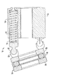
図は、本発明に係わる軸流ピストンポンプ10を示す。この軸流ピストンポンプ10は、シリンダブロック12を備え、このシリンダブロック12の内部に、ピストン本体14が配置されている。ピストン本体14は、細長いボア16を有し、このボアは、ピストン本体を貫通しており、ボア16には、スプリング要素18が嵌合できるようになっている。従って、スプリング要素18は、一端がピストン本体14の内側壁に係合し、他端がシリンダブロック12の壁に係合するようになっている。
The figure shows an
ピストン本体14の第1端部には、ボール20が設けられており、このボール20は、疑似スリッパーと見なすことができるスリッパー要素22に、旋回自在に接続されている。この疑似スリッパー22は、減摩擦スラストベアリング24に係合し、スラストベアリング24は、第1レース要素26と、第2レース要素28とを有し、双方のレース要素の間に、ベアリング要素30が挟持されている。減摩擦スラストベアリング24には、斜板(図示せず)が作動自在に接続されている。
A
図2は、スリッパー要素22が雄型となっている図1の別の実施例を示す。この実施例では、ピストン本体14は、弧状の雄型スリッパー要素22が嵌合しうる雌型溝32を有する。
FIG. 2 shows another embodiment of FIG. 1 in which the
作動時において、スプリング18は、ピストン本体14に保持力を発生するので、追加部品は不要である。ピストン本体14が移動する際に、スリッパー要素22は、ピストン本体14のボール部分20を中心として旋回または回転するので、減摩擦スラストベアリング24にかかるピストン力は分散される。
In operation, the
シリンダブロック12が回転し続けると、ピストン14は、それらのシリンダボアの内外を往復動し続ける。このようにして、液圧流体は押しのけられ、液圧動力ユニットは、液圧ポンプまたは液圧モータとして作動する。
As the
シリンダボア16内でスプリング18を使用することにより、スリッパー保持機構が不要となるので、複雑で、かつ高価な部品が不要となる。更に疑似スリッパー構造は、ブルノーズ軸流ピストンと比較して、接触応力を小さくし、かつブルノーズ軸流ピストンと比較して、ピストンの寿命を長くできる。従って、本発明は、ブルノーズピストン装置のコスト範囲により近いレベルの低コストであって、スリッパータイプの装置の高性能に近似させようとするものである。
The use of the
本発明は、スリッパータイプの軸流ピストン装置で見られるような静水圧バランス膜を必要としないので、ピストンを介してオイルが失われることはなく、ピストンの効率も低下しない。更に、当業者であれば、ボア16の内部またはオプションとして、ボア16の外部にピストン要素18を設けても、このピストン要素が保持機能を実行できることが理解できると思う。
The present invention does not require a hydrostatic balance membrane as found in slipper type axial piston devices, so no oil is lost through the piston and the efficiency of the piston is not reduced. Furthermore, those skilled in the art will appreciate that the piston element can perform the holding function even if a
減摩擦スラストベアリング24は、更にブルノーズタイプの軸流ピストンポンプと比較して、接触応力を小さくできる。この減摩擦スラストベアリングは、ボールベアリング、ローラーベアリング、テーパ付きローラーベアリング、または別の適当なベアリングから成る群のうちの任意の1つでよい。 The friction-reducing thrust bearing 24 can further reduce the contact stress compared to a bull nose type axial piston pump. The friction reducing thrust bearing may be any one of the group consisting of a ball bearing, a roller bearing, a tapered roller bearing, or another suitable bearing.
更に静水圧膜を不要にし、膜を形成するのに使用されるオイルの漏れを解消することにより、損失が少なくなり、効率が改善される。 Further, by eliminating the hydrostatic pressure membrane and eliminating the leakage of oil used to form the membrane, losses are reduced and efficiency is improved.
最後に、標準的な構造の比較的大きく、質量の大きいスリッパーを、本発明の疑似スリッパーと置換することにより、往復動する質量を低減できる。このように、本発明の目的のすべてを達成できる。 Finally, the reciprocating mass can be reduced by replacing a relatively large, high mass slipper of standard construction with the pseudo-slipper of the present invention. In this way, all of the objects of the present invention can be achieved.
当業者であれば、本発明の要旨から逸脱することなく、装置について、種々の変更を行うことができることが理解できると思う。かかる変形および変更のいずれも、特許請求の範囲に入るものであり、特許請求の範囲によってカバーされるものである。 Those skilled in the art will appreciate that various modifications can be made to the apparatus without departing from the spirit of the invention. All such variations and modifications are intended to be within the scope of the claims and are covered by the claims.
10 軸流ピストンポンプ
12 シリンダブロック
14 ピストン本体
16 ボア
18 スプリング要素
20 ボール
22 疑似スリッパー
24 減摩擦スラストベアリング
26 第1レース要素
28 第2レース要素
30 ベアリング要素
32 雌型溝
DESCRIPTION OF
Claims (3)
前記ピストンには、前記疑似スリッパーが旋回自在に接続されており、
更に、第1レース要素および第2レース要素を有する減摩擦スラストを備え、
これら第1および第2レース要素は、これらの間に位置し、かつスリッパーに直接係合するベアリング要素に対して平行な関係となっている疑似スリッパーを備える軸流ピストンポンプ。 Comprising at least one elongate piston disposed inside the pump, which is fitted with a spring for generating pressure on the pseudo-slipper;
The pseudo slipper is pivotally connected to the piston,
And a friction reducing thrust having a first race element and a second race element,
An axial piston pump comprising a pseudo slipper, wherein the first and second race elements are in between and in parallel relation to a bearing element that directly engages the slipper.
前記ピストンに強固に接続されたスプリングと、
前記スプリングがスリッパー要素にかかる保持力を発生するように、前記ピストン本体に旋回自在に接続されたスリッパー要素と、
前記スリッパー要素に直接係合する減摩擦スラストベアリングとを備えることを特徴とする、シリンダブロックを有する軸流ピストンポンプ。 An elongated piston body having a bore disposed in the cylinder block;
A spring firmly connected to the piston;
A slipper element pivotally connected to the piston body such that the spring generates a holding force on the slipper element;
An axial piston pump having a cylinder block, comprising: a friction reducing thrust bearing that directly engages the slipper element.
Applications Claiming Priority (1)
| Application Number | Priority Date | Filing Date | Title |
|---|---|---|---|
| US10/819,883 US20050226737A1 (en) | 2004-04-07 | 2004-04-07 | Axial piston hydraulic power unit with pseudo slippers |
Publications (2)
| Publication Number | Publication Date |
|---|---|
| JP2005299645A true JP2005299645A (en) | 2005-10-27 |
| JP2005299645A5 JP2005299645A5 (en) | 2008-10-02 |
Family
ID=35060724
Family Applications (1)
| Application Number | Title | Priority Date | Filing Date |
|---|---|---|---|
| JP2005090563A Pending JP2005299645A (en) | 2004-04-07 | 2005-03-28 | Axial-flow piston hydraulic power unit with false slipper |
Country Status (3)
| Country | Link |
|---|---|
| US (1) | US20050226737A1 (en) |
| JP (1) | JP2005299645A (en) |
| CN (1) | CN1680714A (en) |
Families Citing this family (7)
| Publication number | Priority date | Publication date | Assignee | Title |
|---|---|---|---|---|
| US7213963B2 (en) | 2003-06-09 | 2007-05-08 | Asml Netherlands B.V. | Lithographic apparatus and device manufacturing method |
| CN102192140A (en) * | 2011-06-13 | 2011-09-21 | 宣伯民 | Swash-plate type axial plunger pump with ball bearing device between swash plate and skid-plate |
| US20140334947A1 (en) * | 2013-05-10 | 2014-11-13 | Caterpillar Inc. | Fluid pump system |
| WO2014187512A1 (en) * | 2013-05-22 | 2014-11-27 | Hydac Drive Center Gmbh | Axial piston pump having a swash-plate type construction |
| CN109653974A (en) * | 2019-02-18 | 2019-04-19 | 阜新北鑫星液压有限公司 | A kind of swash plate plunger pump |
| CN112983772B (en) * | 2021-03-30 | 2022-08-19 | 中航力源液压股份有限公司 | Axial plunger pump return device capable of reducing wear of sliding shoe |
| CN113431757B (en) * | 2021-06-25 | 2022-02-22 | 江苏可奈力机械制造有限公司 | High-efficiency high-speed microminiature hydraulic pump |
Citations (5)
| Publication number | Priority date | Publication date | Assignee | Title |
|---|---|---|---|---|
| JPS60116082A (en) * | 1983-11-29 | 1985-06-22 | Nippon Telegr & Teleph Corp <Ntt> | Individual discrimination method |
| JPS6231778A (en) * | 1985-05-01 | 1987-02-10 | ニユプロ コムパニ− | Flow control valve |
| JPS6357877A (en) * | 1986-08-28 | 1988-03-12 | コマ−シヤル シアリング インコ−ポレ−テツド | Axial piston pump |
| JPH07280063A (en) * | 1994-04-08 | 1995-10-27 | Kubota Corp | Hydraulic transmission |
| JPH10318123A (en) * | 1997-05-19 | 1998-12-02 | Honda Motor Co Ltd | High pressure fuel pump |
Family Cites Families (41)
| Publication number | Priority date | Publication date | Assignee | Title |
|---|---|---|---|---|
| USRE25850E (en) * | 1965-09-07 | Variable volume hydraulic pump | ||
| US1487965A (en) * | 1921-01-05 | 1924-03-25 | Anthony G M Michell | Rotary reciprocating engine |
| US2392543A (en) * | 1939-06-22 | 1946-01-08 | Mercier Jean | Pump |
| US2969810A (en) * | 1955-12-27 | 1961-01-31 | Edward C Dudley | Wobble plate pump |
| US2941475A (en) * | 1957-05-24 | 1960-06-21 | Dynex Inc | Hydraulic pump |
| US3009423A (en) * | 1957-09-23 | 1961-11-21 | Applied Power Ind Inc | Hydraulic pump valve spacer |
| US2945444A (en) * | 1957-09-23 | 1960-07-19 | Dynex Inc | Hydraulic pump |
| US3221564A (en) * | 1962-01-18 | 1965-12-07 | Hydro Kinetics Inc | Piston shoe construction for axial piston pump |
| US3175510A (en) * | 1962-10-16 | 1965-03-30 | Amato Michael A D | Variable displacement pump |
| US3304886A (en) * | 1965-11-12 | 1967-02-21 | Borg Warner | Variable displacement check valve pump |
| US3514223A (en) * | 1968-08-19 | 1970-05-26 | Applied Power Ind Inc | Hydraulic pump |
| GB1335666A (en) * | 1970-03-31 | 1973-10-31 | Lucas Industries Ltd | Hydraulic wheel motor unit |
| US3754842A (en) * | 1971-05-13 | 1973-08-28 | Gen Motors Corp | Hydraulic pump |
| US3951569A (en) * | 1975-05-02 | 1976-04-20 | General Motors Corporation | Air conditioning compressor |
| US4174191A (en) * | 1978-01-18 | 1979-11-13 | Borg-Warner Corporation | Variable capacity compressor |
| US4568252A (en) * | 1980-03-07 | 1986-02-04 | Kabushiki Kaisha Toyoda Jidoshokki Seisakusho | Swash-plate type compressor |
| US4781540A (en) * | 1985-12-05 | 1988-11-01 | Kabushiki Kaisha Toyoda Jidoshokki Seisakusho | Piston type compressor for air conditioning unit having asymmetric valve mechanism |
| US4757795A (en) * | 1986-04-21 | 1988-07-19 | Stanadyne, Inc. | Method and apparatus for regulating fuel injection timing and quantity |
| US4936774A (en) * | 1987-03-25 | 1990-06-26 | Stoller Arnold E | Orthodontic mirror image brackets to removably receive the end portions of lingual arch wires |
| US4815358A (en) * | 1988-01-27 | 1989-03-28 | General Motors Corporation | Balanced variable stroke axial piston machine |
| US4898077A (en) * | 1988-09-06 | 1990-02-06 | Teleflex Incorporated | Self-bleeding hydraulic pumping apparatus |
| US4976284A (en) * | 1990-01-16 | 1990-12-11 | General Motors Corporation | Reed valve for piston machine |
| US5147190A (en) * | 1991-06-19 | 1992-09-15 | General Motors Corporation | Increased efficiency valve system for a fluid pumping assembly |
| JPH06117368A (en) * | 1992-10-02 | 1994-04-26 | Toyota Autom Loom Works Ltd | Reciprocating compressor |
| JP3232544B2 (en) * | 1993-11-24 | 2001-11-26 | 株式会社豊田自動織機 | Weir structure of vehicle air conditioning compressor |
| US5421243A (en) * | 1994-03-21 | 1995-06-06 | General Motors Corporation | Compact refrigerant compressor |
| US5466130A (en) * | 1994-07-26 | 1995-11-14 | Kobelt; Jacob | Helm pump |
| US5931644A (en) * | 1995-03-30 | 1999-08-03 | Caterpillar Inc. | Precision demand axial piston pump with spring bias means for reducing cavitation |
| JPH09280160A (en) * | 1996-01-04 | 1997-10-28 | Sauer Inc | Hydrostatic pump, and extending slipper for rotary cylinder of motor |
| DE19636274C2 (en) * | 1996-09-06 | 2001-07-26 | Sauer Sundstrand Gmbh & Co | Plain bearing with self-adjusting load capacity |
| US5788469A (en) * | 1996-12-13 | 1998-08-04 | Chrysler Corporation | Piston type liquid fuel pump with an improved outlet valve |
| US5755562A (en) * | 1996-12-13 | 1998-05-26 | Chrysler Corporation | Thrust reduction plate for an axial piston fuel pump |
| US5836749A (en) * | 1996-12-13 | 1998-11-17 | Chrysler Corporation | Piston type liquid fuel pump with an improved inlet valve |
| JP3703610B2 (en) * | 1997-08-06 | 2005-10-05 | カヤバ工業株式会社 | Axial piston pump or motor |
| JP3849825B2 (en) * | 1997-10-20 | 2006-11-22 | カヤバ工業株式会社 | Axial piston pump |
| US6092998A (en) * | 1998-03-20 | 2000-07-25 | Devilbiss Air Power Company | Pump for a pressure washer |
| US6352017B1 (en) * | 1999-01-21 | 2002-03-05 | Samjoo Machinery Co., Ltd. | Hydraulic pump |
| US6113359A (en) * | 1999-06-22 | 2000-09-05 | Eaton Corporation | Axial piston pump and relieved valve plate therefor |
| US6217289B1 (en) * | 2000-04-20 | 2001-04-17 | The Rexroth Corporation | Axial piston pump with auxiliary pump |
| US6338293B1 (en) * | 2000-06-30 | 2002-01-15 | Sauer-Danfoss Inc. | Reduced oil volume piston assembly for a hydrostatic unit |
| US6786704B2 (en) * | 2001-11-02 | 2004-09-07 | Denso Corporation | Compressor with single shaft support |
-
2004
- 2004-04-07 US US10/819,883 patent/US20050226737A1/en not_active Abandoned
-
2005
- 2005-03-28 JP JP2005090563A patent/JP2005299645A/en active Pending
- 2005-04-05 CN CN200510064891.8A patent/CN1680714A/en active Pending
Patent Citations (5)
| Publication number | Priority date | Publication date | Assignee | Title |
|---|---|---|---|---|
| JPS60116082A (en) * | 1983-11-29 | 1985-06-22 | Nippon Telegr & Teleph Corp <Ntt> | Individual discrimination method |
| JPS6231778A (en) * | 1985-05-01 | 1987-02-10 | ニユプロ コムパニ− | Flow control valve |
| JPS6357877A (en) * | 1986-08-28 | 1988-03-12 | コマ−シヤル シアリング インコ−ポレ−テツド | Axial piston pump |
| JPH07280063A (en) * | 1994-04-08 | 1995-10-27 | Kubota Corp | Hydraulic transmission |
| JPH10318123A (en) * | 1997-05-19 | 1998-12-02 | Honda Motor Co Ltd | High pressure fuel pump |
Also Published As
| Publication number | Publication date |
|---|---|
| CN1680714A (en) | 2005-10-12 |
| US20050226737A1 (en) | 2005-10-13 |
Similar Documents
| Publication | Publication Date | Title |
|---|---|---|
| US12540605B2 (en) | Hydraulic pump with swash plate tilt control | |
| US20090290996A1 (en) | Bent Axis Type Variable Displacement Pump/Motor | |
| US8074558B2 (en) | Axial piston device having rotary displacement control | |
| US6368072B1 (en) | Hydraulic pump | |
| US5251536A (en) | Axial piston pump with off-center pivot | |
| JP2005299645A (en) | Axial-flow piston hydraulic power unit with false slipper | |
| US5647266A (en) | Hold-down mechanism for hydraulic pump | |
| JP2017180448A (en) | Liquid pressure rotation machine | |
| JP2001263197A (en) | Pumps for supplying fuel injection systems and hydraulic valve controls for internal combustion engines | |
| JP2005299645A5 (en) | ||
| US5490444A (en) | Piston pump with improved hold-down mechanism | |
| JP5634119B2 (en) | Axial piston pump | |
| CN108412717B (en) | A hydrostatic support device and control method at the bottom of a sliding shoe of an unmanned ship water hydraulic pump | |
| CN204458236U (en) | A kind of plunger piston variable hydraulic pump | |
| US20050238501A1 (en) | Revolving yoke load-sensitive displacement-varying mechanism for axial piston hydraulic pump | |
| JP2004169693A (en) | Electrohydraulic pump displacement control part having proportional force feedback | |
| JP2005201175A (en) | Variable capacity swash plate type hydraulic rotating machine | |
| CN107795448B (en) | Hydrostatic Axial Piston Machine | |
| JP2014066189A (en) | Variable capacity type piston pump | |
| CN222596231U (en) | Constant power controller with pressure control for high-pressure plunger pump | |
| WO2015118398A1 (en) | Low friction compact servo piston assembly | |
| CN111828275A (en) | Axial piston machine | |
| EP3617501B1 (en) | Hydraulic system | |
| CA2405884A1 (en) | Reversible pump for driving hydraulic cylinders having a single piston that simultaneously reciprocates and rotates | |
| JPH1068378A (en) | Swash plate type hydraulic rotary machine |
Legal Events
| Date | Code | Title | Description |
|---|---|---|---|
| A521 | Request for written amendment filed |
Free format text: JAPANESE INTERMEDIATE CODE: A523 Effective date: 20071022 |
|
| A621 | Written request for application examination |
Free format text: JAPANESE INTERMEDIATE CODE: A621 Effective date: 20080125 |
|
| A521 | Request for written amendment filed |
Free format text: JAPANESE INTERMEDIATE CODE: A523 Effective date: 20080818 |
|
| A977 | Report on retrieval |
Free format text: JAPANESE INTERMEDIATE CODE: A971007 Effective date: 20100826 |
|
| A131 | Notification of reasons for refusal |
Free format text: JAPANESE INTERMEDIATE CODE: A131 Effective date: 20100907 |
|
| A02 | Decision of refusal |
Free format text: JAPANESE INTERMEDIATE CODE: A02 Effective date: 20110329 |